EP3321060A1 - Spritzgiessdüsenvorrichtung - Google Patents
Spritzgiessdüsenvorrichtung Download PDFInfo
- Publication number
- EP3321060A1 EP3321060A1 EP17201485.4A EP17201485A EP3321060A1 EP 3321060 A1 EP3321060 A1 EP 3321060A1 EP 17201485 A EP17201485 A EP 17201485A EP 3321060 A1 EP3321060 A1 EP 3321060A1
- Authority
- EP
- European Patent Office
- Prior art keywords
- spacer
- injection molding
- material tube
- mounting plate
- guide sleeve
- Prior art date
- Legal status (The legal status is an assumption and is not a legal conclusion. Google has not performed a legal analysis and makes no representation as to the accuracy of the status listed.)
- Granted
Links
Images


Classifications
-
- B—PERFORMING OPERATIONS; TRANSPORTING
- B29—WORKING OF PLASTICS; WORKING OF SUBSTANCES IN A PLASTIC STATE IN GENERAL
- B29C—SHAPING OR JOINING OF PLASTICS; SHAPING OF MATERIAL IN A PLASTIC STATE, NOT OTHERWISE PROVIDED FOR; AFTER-TREATMENT OF THE SHAPED PRODUCTS, e.g. REPAIRING
- B29C45/00—Injection moulding, i.e. forcing the required volume of moulding material through a nozzle into a closed mould; Apparatus therefor
- B29C45/17—Component parts, details or accessories; Auxiliary operations
- B29C45/26—Moulds
- B29C45/27—Sprue channels ; Runner channels or runner nozzles
- B29C2045/2759—Nozzle centering or guiding means
-
- B—PERFORMING OPERATIONS; TRANSPORTING
- B29—WORKING OF PLASTICS; WORKING OF SUBSTANCES IN A PLASTIC STATE IN GENERAL
- B29C—SHAPING OR JOINING OF PLASTICS; SHAPING OF MATERIAL IN A PLASTIC STATE, NOT OTHERWISE PROVIDED FOR; AFTER-TREATMENT OF THE SHAPED PRODUCTS, e.g. REPAIRING
- B29C45/00—Injection moulding, i.e. forcing the required volume of moulding material through a nozzle into a closed mould; Apparatus therefor
- B29C45/17—Component parts, details or accessories; Auxiliary operations
- B29C45/26—Moulds
- B29C45/27—Sprue channels ; Runner channels or runner nozzles
- B29C2045/2764—Limited contact between nozzle and mould
-
- B—PERFORMING OPERATIONS; TRANSPORTING
- B29—WORKING OF PLASTICS; WORKING OF SUBSTANCES IN A PLASTIC STATE IN GENERAL
- B29C—SHAPING OR JOINING OF PLASTICS; SHAPING OF MATERIAL IN A PLASTIC STATE, NOT OTHERWISE PROVIDED FOR; AFTER-TREATMENT OF THE SHAPED PRODUCTS, e.g. REPAIRING
- B29C45/00—Injection moulding, i.e. forcing the required volume of moulding material through a nozzle into a closed mould; Apparatus therefor
- B29C45/17—Component parts, details or accessories; Auxiliary operations
- B29C45/26—Moulds
- B29C45/27—Sprue channels ; Runner channels or runner nozzles
- B29C2045/2766—Heat insulation between nozzle and mould
Definitions
- the invention relates to an injection molding device according to claim 1.
- Injection molding dies are used in injection molds in order to supply a flowable mass to a separable tool block (mold cavity) at a predeterminable temperature under high pressure. They usually have a nozzle body in the form of a material tube, in which a flow channel for the flowable mass is formed. This ends in a nozzle mouthpiece, which is inserted into the end of the material tube and forms the outlet opening for the flow channel.
- an electric heater is provided, which concentrically surrounds the material pipe or the flow channel formed therein. This makes it possible to keep the flowable mass into the nozzle tip at a constant temperature.
- a thermal break between the The hot housing and the mostly cooled tool ensures that the nozzle does not freeze - especially in the area of the nozzle tip - and at the same time the tool (mold cavity) is not heated.
- a temperature sensor is usually used.
- Material pipe and heating can be designed as separate components, the heater is integrated together with the temperature sensor in a sheath, which is pushed circumferentially on the material pipe. But you can also integrate the heater in the material pipe, for example, as a tubular heater or as a coil, or you bring the cohesive material as a layer heating on the material pipe.
- the material pipe usually sits in a housing which is in communication with a distributor plate in the injection mold in such a way that the flow channel in the material tube is in flow communication with the flow channels in the distributor plate. Between the material pipe and the housing, an air gap for thermal insulation is formed. For a stable bearing, the housing is supported on the front and rear end of the material pipe. The air volume in the air gap is sealed as far as possible. The disadvantage here are thermal bridges at the contact points to the material pipe. The housing in turn is supported on the distributor plate and / or the mold plate, which enhances the heat flow from the material tube to the housing. This not only leads to an increased energy requirement for the heating, but also to a thermal unequal distribution over the length of the material tube.
- the present invention is based on the object to provide an improved injection molding device, which allows a uniform temperature profile over the length of a material pipe
- the invention relates to an injection molding nozzle device with at least one material tube, wherein the at least one material tube extends in a longitudinal direction.
- a flow channel for a flowable mass is further formed, wherein the at least one material tube at a front end of the flow channel has a nozzle tip with at least one outlet opening for the flowable mass.
- the at least one material tube At a rear End of the flow channel, the at least one material tube at least one inlet opening for the flowable mass and is fixed to a mounting plate.
- the at least one material tube is heated with a heating device and arranged in a housing, wherein it is arranged without contact inside the housing in a longitudinally aligned section with the exception of the heating device on the outer circumference.
- the section is arranged adjacent to the mounting plate and extends in the direction of the front end.
- the housing has a one-piece spacer and each material tube a guide sleeve, each guide sleeve is attached to the spacer and wherein the spacer is fixed to the mounting plate and defines the distance between the guide sleeve and mounting plate.
- the advantage of this is that the material pipe no thermal bridges are formed by other components in the vicinity of the mounting plate, since the housing is not supported on the material pipe. Accordingly, little heat flows from the material pipe here. The energy required to operate the heater is thereby lower and it is achieved a more uniform temperature distribution over the length of the material tube. Furthermore, a simple holder and positioning of the guide sleeves for the material pipes is possible by a one-piece spacer.
- the spacer is designed according to one embodiment as a peripheral frame which radially surrounds the at least one material tube and is spaced from the at least one material tube.
- the frame may consist, for example, of metal or a ceramic.
- the frame can have any geometry.
- limits for the design options arise from the requirement that the spacer must withstand the forces based on the injection pressures of up to 2000 bar, which is why corresponding machine nozzle contact forces are present in order to keep the mold closed.
- the frame has at least one recess through which at least one material tube is accessible from outside the frame.
- the at least one recess is a wiring and power supply of the heater, as well as the reading of existing within the frame temperature sensors possible.
- the recesses are preferably designed so that through the recesses existing contacts of the heater are easily accessible. Furthermore, the recesses are preferably dimensioned so that they affect the stability of the frame as little as possible.
- the at least one guide sleeve has a coupling means.
- the coupling means can be designed for a non-positive and / or positive connection with the spacer.
- the coupling means is preferably formed integrally with the guide sleeve to ensure sufficient stability.
- the coupling means may be a part of a bayonet closure which is designed to engage in a correspondingly opposite coupling means of the spacer.
- the coupling means is an external thread.
- the external thread is preferably arranged on a rear, the mounting plate facing the end of the guide sleeve.
- internal threads are provided in this case to the external threads, so that the at least one guide sleeve can be screwed into the spacer.
- a stop is preferably formed in the spacer, which limits the possible depth of engagement of a guide sleeve.
- the engagement depth of the guide sleeve is chosen exactly so that the guide sleeve does not protrude beyond the end face of the spacer with which the spacer rests on the mold plate. So a thermal bridge can be avoided at this point.
- an air gap of about 1 mm remains between the guide sleeve and the mold plate.
- the coupling means is a projection on an end of the at least one material tube facing the rear of the mounting plate, wherein the housing has an additional fixing element which can be fixed to the spacer such that the coupling means between the fixing element and the spacer is clamped.
- the fixing element may be a plateau arrangement in which recesses for receiving the at least one guide sleeve are formed.
- the fixing element For attachment of the at least one guide sleeve, it can first be passed through the recess until the guide sleeve rests with its projection on a surface of the fixing element. Subsequently, the fixing element is attached to the spacer, for example screwed, so that the projection between the fixing and spacer is clamped.
- a receiving geometry for the coupling means is formed in the spacer and / or the fixing element.
- the receiving geometry may be, for example, a recess which is adapted in its shape to the shape of the projection.
- a permanent connection can also be provided.
- guide sleeve and spacers for example, materially connected, for example, be welded.
- the spacer is attachable to the mounting plate.
- the spacer is indirectly or directly bolted to the mounting plate.
- eyelets can be arranged in or on the spacer into which a screw can engage, which in turn into the mounting plate is screwed in.
- the eyelets are preferably made in one piece with the spacer.
- An indirect screwing for example, be realized by the above-described fixing of the housing is screwed to the mounting plate, that by tightening the screws, the fixing element exerts a force on the spacer towards the mounting plate. As a result, the spacer between the mounting plate and the fixing can be clamped. It can be ensured by appropriate positioning and anti-rotation the correct orientation of the spacer.
- the heating device is arranged without contact in the section with the exception of the material pipes. Accordingly, heat from the heater in the section also does not leak heat to components other than the material pipe. Inadvertent heating of an opposing mold plate is also avoided.
- the length of the section in the longitudinal direction is at least half the total length of the material tube in the longitudinal direction.
- a coupling means for fixing the material pipe to the mounting plate is formed at the rear end on each of the material pipes.
- the coupling means is a thread, in particular an external thread, or a bayonet means. This allows a firm and tight connection.
- each of the material pipes peripherally supports an electric heater of the heater, and the heating elements are arranged without contact in the region of the portion except for the material pipe.
- These heating elements can be designed in particular sleeve or sleeve shape for uniform temperature.
- the heating elements preferably extend from the front end of the material tube to the stop or the mounting plate at the rear end.
- the heating device in each case has a heating cartridge. This sits either in the flow channel of the material pipes or else it is inserted in the longitudinal direction in the wall of the material pipes.
- the first variant is one Direct heating of the fluid mass in the flow channel and inside the material pipe possible.
- the second variant allows easy installation and interchangeability.
- At least one positioning element is formed on the spacer, which is designed for positioning the injection molding device in an injection mold.
- the positioning elements may be pins or bolts which project from the spacer and, in the mounted position of the injection molding nozzle device, engage in corresponding receptacles of a molding plate of an injection molding tool.
- such positioning elements can also be formed on the fixing element.
- the at least one guide sleeve is supported indirectly or directly exclusively at the front end of the at least one material tube.
- the at least one guide sleeve is divided into two, wherein a front end of the sleeve consists of a first material and wherein a rear end of the sleeve consists of a second material, wherein the front end of the sleeve is connected to the rear end of the sleeve.
- the front sleeve end may be connected to the rear sleeve end via a screw or bayonet connection.
- the connection of the sleeve ends can also be a cohesive connection.
- the first material of the front sleeve end is preferably made of a metal with little heat conductivity, so that heat transfer from the material tube to the guide sleeve is reduced.
- the front sleeve end is made of titanium.
- FIG. 1 an injection molding nozzle device 1 is shown in perspective view.
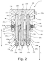
- Fig. 2 shows a longitudinal section through the injection molding device 1 after Fig. 1
- Fig. 3 one to the representation of Fig. 2 vertical longitudinal section through the injection molding device 1 shows.
- the Spritzg hassledüsenvorraum 1 has three identical material tubes 10 a, 10 b, 10 c, of which in the Fig. 1 and 2 three and in Fig. 3 only one is visible.
- Each of the material tubes 10a, 10b, 10c extends in a longitudinal direction L, ie the material tubes 10a, 10b, 10c are aligned parallel to each other.
- a flow channel 11a is formed for a flowable mass.
- each of the material pipes 10a, 10b, 10c has at a front end 12a of the flow channel 11a via a nozzle tip 14a, 14b, 14c with at least one flowable material outlet opening.
- the nozzle tips 14, 14 a, 14 b, 14 c are all identical and in the FIGS. 1 . 2 . 3 . 4a ) and 5a ) executed as open nozzle tips.
- the nozzle tips 14, 14 a, 14 b, 14 c are formed with a needle valve, as in the FIGS. 4b ) and 5b ) is shown.
- Each of the material tubes 10a, 10b, 10c has at least one inlet opening 16a for the flowable mass at a rear end 13a of the flow channel 11a and a stop 17a for defined positioning on a mounting plate 50.
- the mounting plate 50 may be, for example, the distributor of an injection mold act. Consequently, the mounting plate 50 be equipped with a heater 51, as exemplified in the FIGS. 1 . 2 and 3 is shown. The heater 51 is inserted into a corresponding groove in the mounting plate 51. As in Fig. 2 and 3 is shown, the mounting plate 50 has a central inlet opening, to which a distributor plate or a central machine nozzle can be connected.
- each of the material pipes 10a, 10b, 10c is heated with a heater 20a, 20b, 20c.
- each material tube 10a, 10b, 10c circumferentially carries a sleeve-shaped heating element, which is connected via terminals 21a, 21b, 21c to a power supply.
- the heating element 10a, 10b, 10c is preferably a carrier sleeve with thick film heating.
- any other heater can be used.
- a coupling means 19a for fixing the material pipe 10a, 10b, 10c to the mounting plate 50 is formed on each of the material pipes 10a, 10b, 10c. It is an external thread in the illustrated embodiment.
- a tool holder can be arranged on each of the material pipes 10a, 10b, 10c in order to screw the coupling means 19a into the mounting plate 50.
- FIGS. 4 a) and b) show a substantially the same structure of a Spritzg phonedüsenvorraum 1.
- the illustrated Spritzg cleverdüsenvorraum 1 each equipped with only a single material pipe 10.
- the show FIGS. 4 b) and 5 b) each injection molding nozzle devices 1 the material tubes 10 are equipped with a nozzle tip 14, which are designed to receive a closure needle.
- a guide 22 for a closure needle is further formed in the flow channel 11.
- Fig. 1 . 2 . 3 . 4 and 5 have in common that each of the material tubes 10, 10a, 10b, 10c in a longitudinally L aligned portion A with the exception of the heater 20, 20a, 20b, 20c is arranged without contact on the outer circumference, wherein the portion A is adjacent to the mounting plate 50 and extends in the direction of the front end 12, 12 a.
- the heating elements of the heating device 20, 20a, 20b, 20c are arranged in the section A with the exception of the material tubes 10, 10a, 10b, 10c without contact. Excepted from this, however, are the connecting lines 21 a, 21 b, 21 c, which lead to the heating elements.
- the length of the section A in the longitudinal direction L more than half the total length of the material tube 10, 10a, 10b, 10c in the longitudinal direction L.
- the section A extends in each case from the distributor 50 to the front end 12, 12a of the material tube 10, 10a, 10b, 10c.
- FIGS. 1 to 5 a housing having at least one integral spacer 44 to which the guide sleeves 30, 30a, 30b, 30c are attached.
- Each of the material tubes 10a, 10b, 10c is arranged with the front end 12a within a guide sleeve 30, 30a, 30b, 30c and protrudes with the rear end 13a and the stop 17a from a rear sleeve end 31, 31a, 31b, 31c of the guide sleeve 30, 30a, 30b, 30c out.
- an air gap S1, S2 is formed between the material pipe 10a, 10b, 10c and the guide sleeve 30, 30a, 30b, 30c.
- the material tube 10, 10 a, 10 b, 10 c at the rear end of the sleeve 31, 31 a, 31 b, 31 c contactless to the guide sleeve 30, 30 a, 30 b, 30 c.
- the guide sleeve 30, 30a, 30b, 30c in the direction of the rear sleeve end 31, 31a, 31b, 31c over at least two thirds of its total length X is contactless to the material tube 10, 10a, 10b, 10c.
- the guide sleeve 30, 30a, 30b, 30c is supported exclusively with a front sleeve end 32, 32a at the front end 12, 12a of the material tube 10, 10a, 10b, 10c on the material tube 10, 10a, 10b, 10c.
- the front sleeve end 32, 32a is made of titanium.
- the guide sleeves 30, 30a, 30b, 30c are identical parts.
- the rear sleeve end 31, 31 a, 31 b, 31 c of the guide sleeves 30, 30 a, 30 b, 30 c is arranged in the longitudinal direction L spaced from the mounting plate 50.
- the guide sleeves 30, 30a, 30b, 30c are each formed in two parts, wherein the front sleeve end 32, 32a of a first material and the rear sleeve end 31, 31a, 31b, 31c consists of a second material.
- the front sleeve end 32, 32a is connected in each case at a coupling point with the rear sleeve end 31, 31a, 31b, 31c.
- the first material consists of a less highly thermally conductive metal, in particular titanium, as the rear end of the sleeve 31, 31 a, 31 b, 31 c.
- FIGS. 1 to 5 Variants shown differ essentially by the structure of the housing in which the material tubes 10, 10a, 10b, 10c are arranged, or in the manner of storage of the guide sleeves 30, 30a, 30b, 30c.
- the spacer 44 is connected on a first side with a fixing element 40 in the form of a holding plate, while it is connected to the mounting plate 50 on a second side.
- a screw 47 is guided in the region of the corners of the fixing element 40 through the fixing element 40 and the spacer 44 and screwed into the mounting plate 50.
- any other detachable or permanent type of connection between fixing element 40 and spacer 44 on the one hand and spacers 44 and mounting plate 50 on the other hand can be used.
- the spacer 44 may be crimped, welded, riveted, pinned, or otherwise permanently or releasably connected to the fuser 40 and / or mounting plate 50.
- a detachable connection has the advantage that for the maintenance of the heating elements, the injection molding device 1 can be easily disassembled into their individual parts.
- the fixing member 40 is spaced from each of the material pipes 10a, 10b, 10c and the heater 20a, 20b, 20c.
- Each of the material tubes 10a, 10b, 10c projects through a respective recess in the fixing element 40.
- the fixing element 40 is aligned transversely to the longitudinal direction L.
- the spacer 44 is designed as a peripheral frame which encloses the material pipes 10a 10b 10c in the area between the mounting plate 50 and the fixing element 40 in the radial direction.
- In the frame side recesses 48 are formed, through which a contacting of the heating elements via the terminals 21 a, 21 b, 21 c is possible.
- the guide sleeves 30a, 30b, 30c each have at their rear end sleeve 31a, 31b, 31c a transversely to the longitudinal direction L projecting coupling means 33a, 33b in the form of a circumferential projection.
- the coupling means 33a, 33b, 33c lies in a receiving geometry 43 in the fixing element 40 and is clamped between the fixing element 40 and the spacer 44.
- positioning 49 On the underside of the fixing element 40 are, as in Fig. 1 is shown, positioning 49 arranged in the form of pins.
- the positioning elements 49 are designed to correctly position and align the injection molding nozzle device 1 in the mold when inserting the injection molding nozzle device 1 into an injection mold.
- the positioning elements 49 are preferably formed integrally with the fixing element 40.
- FIGS. 4 a) and b) show one to the FIGS. 1 to 3 alternative storage of the guide sleeve 30 in a spacer 44.
- the guide sleeves 30 at its rear Sleeve end 31 also a projection on, but at the different than in the FIGS. 1 to 3 a coupling means 33 is arranged in the form of an external thread.
- a receiving geometry 43 is formed, which has an internal thread, which is opposite to the external thread of the coupling means 33. Consequently, the guide sleeve 30 can be screwed with its rear end in the spacer 44.
- the receiving geometry 43 is formed so that it forms a stop for the attachment of the guide sleeve 30 such that the projection of the guide sleeve 30 when screwing the guide sleeve 30 in the receiving geometry 43 completely sinks in the receiving geometry 43 and not down on the spacer 44 survives.
- an additional fixing element 40 is again provided, which can be clamped by appropriate screws 47, which are guided from above through the mounting plate 50 against the mounting plate 50, so that the spacer between the mounting plate 50 and fixing 40th is trapped. Due to the complete sinking of the projection of the guide sleeve 30 in the receiving geometry 43 of the spacer 44, in the assembled state, the projection of the guide sleeve 30 is not on top of the fixing member 40. Consequently, no direct heat exchange between fixing element 40 and guide sleeve 30 takes place here. This is particularly advantageous when the fixing element 40 is the cooled mold plate of an injection mold.
- Fig. 5 is like in Fig. 4 the guide sleeve 30 is screwed by means of a corresponding thread 33 in a receiving geometry 43 of the spacer 44.
- the spacer 44 is bolted directly to the mounting plate 50 and not clamped by an additional fixing element 40.
- an additional attachment is provided for fixing the injection molding nozzle device 1 on a mold plate 40.
- an additional spacer 60 is screwed into a corresponding recess in the mounting plate 50.
- a screw 61 is passed, which engages in the mold plate 40 and the mold plate 40 pulls against the spacer 60.
- the length of the spacer 60 thus defines the distance between the mounting plate 50 and the mold plate 40. If the spacer 60 is longer than the spacer 44, the guide sleeve 30 is not on top of the mold plate 40. Thus, in turn, the heat exchange between the mold plate 40 and guide sleeve 30 can be reduced.
Landscapes
- Engineering & Computer Science (AREA)
- Manufacturing & Machinery (AREA)
- Mechanical Engineering (AREA)
- Injection Moulding Of Plastics Or The Like (AREA)
- Moulds For Moulding Plastics Or The Like (AREA)
Abstract
Description
- Die Erfindung betrifft eine Spritzgießdüsenvorrichtung gemäß Anspruch 1.
- Spritzgießdüsen werden in Spritzgießwerkzeugen eingesetzt, um eine fließfähige Masse bei einer vorgebbaren Temperatur unter hohem Druck einem trennbaren Werkzeugblock (Formnest) zuzuführen. Sie haben gewöhnlich einen Düsenkörper in Form eines Materialrohrs, in dem ein Strömungskanal für die fließfähige Masse ausgebildet ist. Dieser endet in einem Düsenmundstück, das endseitig in das Materialrohr eingesetzt ist und die Austrittsöffnung für den Strömungskanal bildet.
- Damit sich die zumeist heiße Masse innerhalb der Düse nicht vorzeitig abkühlt, ist eine elektrische Heizung vorgesehen, welche das Materialrohr bzw. den darin ausgebildeten Strömungskanal konzentrisch umgibt. Dadurch ist es möglich, die fließfähige Masse bis in die Düsenspitze hinein auf einer konstanten Temperatur zu halten. Eine thermische Trennung zwischen dem heißem Gehäuse und dem meist gekühlten Werkzeug sorgt dafür, dass die Düse - insbesondere im Bereich der Düsenspitze - nicht einfriert und gleichzeitig das Werkzeug (Formnest) nicht erwärmt wird. Zur Überwachung der Temperatur verwendet man gewöhnlich einen Temperaturfühler.
- Materialrohr und Heizung können als separate Bauelemente ausgeführt sein, wobei die Heizung gemeinsam mit dem Temperaturfühler in einer Ummantelung integriert ist, die umfangsseitig auf das Materialrohr aufgeschoben wird. Man kann die Heizung aber auch in das Materialrohr integrieren, beispielsweise als Rohrheizkörper oder als Rohrschlange, oder man bringt die Heizung stoffschlüssig als Schichtheizung auf dem Materialrohr auf.
- Das Materialrohr sitzt meist in einem Gehäuse, das derart mit einer Verteilerplatte im Spritzgießwerkzeug in Verbindung steht, dass der Strömungskanal im Materialrohr mit den Strömungskanälen in der Verteilerplatte in Strömungsverbindung steht. Zwischen dem Materialrohr und dem Gehäuse ist ein Luftspalt zur thermischen Isolation ausgebildet. Für eine stabile Lagerung stützt sich das Gehäuse auf dem vorderen und hinteren Ende des Materialrohrs ab. Das Luftvolumen im Luftspalt ist so weitestgehend abgedichtet. Nachteilhaft sind hierbei entstehende Wärmebrücken an den Kontaktstellen zum Materialrohr. Das Gehäuse wiederum stützt sich an der Verteilerplatte und/oder der Formplatte ab, was den Wärmeabfluss vom Materialrohr auf das Gehäuse noch verstärkt. Dies führt nicht nur zu einem erhöhten Energiebedarf für die Beheizung, sondern auch zu einer thermischen Ungleichverteilung über der Länge des Materialrohrs.
- Der vorliegenden Erfindung liegt demgegenüber die Aufgabe zugrunde eine verbesserte Spritzgießdüsenvorrichtung zu schaffen, welche ein gleichmäßiges Temperaturprofil über die Länge eines Materialrohrs ermöglicht
- Hauptmerkmale der Erfindung sind im kennzeichnenden Teil von Anspruch 1 angegeben. Ausgestaltungen sind Gegenstand der Ansprüche 2 bis 14.
- Die Erfindung betrifft eine Spritzgießdüsenvorrichtung mit wenigstens einem Materialrohr, wobei sich das wenigstens eine Materialrohr in einer Längsrichtung erstreckt. In dem wenigstens einen Materialrohr ist ferner ein Strömungskanal für eine fließfähige Masse ausgebildet, wobei das wenigstens eine Materialrohr an einem vorderen Ende des Strömungskanals eine Düsenspitze mit wenigstens einer Austrittsöffnung für die fließfähige Masse aufweist. An einem hinteren Ende des Strömungskanals weist das wenigstens eine Materialrohr wenigstens eine Eintrittsöffnung für die fließfähige Masse auf und ist an einer Montageplatte festgelegt. Das wenigstens eine Materialrohr ist mit einer Heizvorrichtung beheizt und in einem Gehäuse angeordnet, wobei es innerhalb des Gehäuses in einem in Längsrichtung ausgerichteten Abschnitt mit Ausnahme der Heizvorrichtung am Außenumfang kontaktlos angeordnet ist. Der Abschnitt ist dabei benachbart zu der Montageplatte angeordnet und erstreckt sich in Richtung des vorderen Endes. Das Gehäuse weist einen einstückigen Abstandshalter und je Materialrohr eine Führungshülse auf, wobei jede Führungshülse an dem Abstandshalter befestigt ist und wobei der Abstandshalter an der Montageplatte festlegbar ist und den Abstand zwischen Führungshülse und Montageplatte definiert.
- Vorteilhaft hieran ist, dass am Materialrohr keine Wärmebrücken durch andere Bauteile in der Nähe der Montageplatte ausgebildet sind, da sich das Gehäuse nicht an dem Materialrohr abstützt. Entsprechend fließt hier wenig Wärme vom Materialrohr ab. Der Energiebedarf zum Betrieb der Heizvorrichtung ist hierdurch geringer und es wird eine gleichmäßigere Temperaturverteilung über die Länge des Materialrohrs erzielt. Ferner ist durch einen einstückigen Abstandshalter eine einfache Halterung und Positionierung der Führungshülsen für die Materialrohre möglich.
- Der Abstandshalter ist dabei nach einer Ausführungsform als umlaufender Rahmen ausgeführt, der das wenigstens eine Materialrohr radial einfasst und von dem wenigstens einen Materialrohr beabstandet ist. Dabei kann der Rahmen beispielweise aus Metall oder einer Keramik bestehen. Durch einen umlaufenden Rahmen, welcher an der Montageplatte befestigt ist und die Führungshülsen trägt, kann ein besonders stabiler Aufbau der Spritzgießdüsenvorrichtung erreicht werden. Eine auf die Führungshülsen oder den Rahmen einwirkende Kraft kann nämlich gleichmäßig über eine große Auflagefläche an die Montageplatte übertragen werden. Der Rahmen muss dabei nicht zwingend über seinen gesamten Umfang an der Montageplatte anliegen. Es ist vielmehr möglich, dass der Rahmen nur punktuell aufliegt. Durch eine punktuelle Auflage des Rahmens kann eine verbesserte thermische Entkopplung des Rahmens und folglich auch der Führungshülsen von der Montageplatte erreicht werden.
- Grundsätzlich kann der Rahmen eine beliebige Geometrie aufweisen. Grenzen für die Gestaltungsmöglichkeiten ergeben sich jedoch aus der Anforderung, dass der Abstandshalter den Kräften basierend auf den Einspritzdrücken von bis zu 2000 bar standhalten muss, weswegen entsprechende Maschinendüsenanlagekräfte vorliegen, um das Formwerkzeug geschlossen halten zu können.
- Vorzugsweise weist der Rahmen dabei wenigstens eine Ausnehmung auf, durch die wenigstens ein Materialrohr von außerhalb des Rahmens zugänglich ist. Durch die wenigstens eine Ausnehmung ist eine Verkabelung und Energieversorgung der Heizvorrichtung, sowie das Auslesen von innerhalb des Rahmens vorhandenen Temperaturfühlern möglich. Dabei sind die Ausnehmungen vorzugsweise so gestaltet, dass durch die Ausnehmungen hindurch vorhandene Kontakte der Heizvorrichtung leicht erreichbar sind. Ferner sind die Ausnehmungen vorzugsweise so dimensioniert, dass sie die Stabilität des Rahmens so wenig wo möglich beeinflussen.
- Zur Festlegung der wenigstens einen Führungshülse an dem Abstandshalter ist nach einer Ausführungsform vorgesehen, dass die wenigstens eine Führungshülse ein Koppelmittel aufweist. Das Koppelmittel kann dabei für eine kraftschlüssige und/oder formschlüssige Verbindung mit dem Abstandshalter ausgebildet sein. Dabei ist das Koppelmittel vorzugsweise einstückig mit der Führungshülse ausgebildet, um eine ausreichende Stabilität zu gewährleisten. Beispielsweise kann es sich bei dem Koppelmittel um einen Teil eines Bajonettverschlusses handeln, welcher dazu ausgebildet ist, in ein entsprechend gegenstückiges Koppelmittel des Abstandshalters einzugreifen.
- Nach einer bevorzugten Ausführungsform handelt es sich bei dem Koppelmittel um ein Außengewinde. Das Außengewinde ist dabei vorzugsweise an einem hinteren, der Montageplatte zugewandten Ende der Führungshülse angeordnet. In dem Abstandshalter sind in diesem Fall zu den Außengewinden gegenstückige Innengewinde vorgesehen, sodass die wenigstens eine Führungshülse in den Abstandshalter eingeschraubt werden kann. Dabei ist in dem Abstandshalter vorzugsweise ein Anschlag ausgebildet, welcher die mögliche Einschraubtiefe einer Führungshülse begrenzt. Bei der Montage der Spritzgießdüsenvorrichtung in einem Spritzgießwerkzeug kann vorgesehen sein, dass sich der Abstandshalter in der montierten Position an der Formplatte eines Spritzgießanlage abstützt. Da die Formplatte üblicherweise gekühlt ist, sollte eine thermische Kontaktierung der Führungshülse und mithin des wenigstens einen Materialrohrs so gut es geht vermieden werden. Hierzu kann nach einer bevorzugten Ausführungsform vorgesehen sein, dass die Einschraubtiefe der Führungshülse genau so gewählt ist, dass die Führungshülse nicht über die Stirnseite des Abstandshalters hervorsteht, mit der der Abstandshalter auf der Formplatte aufliegt. So kann eine Wärmebrücke an dieser Stelle vermieden werden. Vorzugsweise verbleibt in dieser Ausführung zwischen der Führungshülse und der Formplatte ein Luftspalt von etwa 1 mm.
- Nach einer hierzu alternativen Ausführungsform handelt es sich bei dem Koppelmittel um eine Auskragung an einem dem hinteren der Montageplatte zugewandten Ende des wenigstens einen Materialrohrs, wobei das Gehäuse ein zusätzliches Fixierelement aufweist, das so an dem Abstandshalter festlegbar ist, dass das Koppelmittel zwischen dem Fixierelement und dem Abstandshalter eingeklemmt ist. Beispielsweise kann es sich bei dem Fixierelement um eine Plateauanordnung handeln, in der Ausnehmungen zur Aufnahme der wenigstens einen Führungshülse ausgebildet sind. Zur Befestigung der wenigstens einen Führungshülse, kann diese zunächst durch die Ausnehmung geführt werden, bis die Führungshülse mit ihrer Auskragung an einer Oberfläche des Fixierelements aufliegt. Anschließend wird das Fixierelement an dem Abstandshalter befestigt, beispielsweise verschraubt, sodass die Auskragung zwischen Fixierelement und Abstandshalter eingeklemmt ist.
- Um die Positionierung und Montage einer Führungshülse mit einer Auskragung zu vereinfachen, ist nach einer weiteren Ausführungsform vorgesehen, dass in dem Abstandshalter und/oder dem Fixierelement eine Aufnahmegeometrie für das Koppelmittel ausgebildet ist. Bei der Aufnahmegeometrie kann es sich beispielsweise um eine Ausnehmung handeln, welche in ihrer Form an die Form der Auskragung angepasst ist. Bei der Montage der Führungshülse kann dann die Auskragung in die entsprechende Aufnahmegeometrie eingesetzt werden, sodass die Führungshülse mit Ihrer Auskragung in der Aufnahmegeometrie gelagert ist. Auf diese Weise kann eine Vorpositionierung der Führungshülse erreicht werden, welche den Zusammenbau der Spritzgießdüsenvorrichtung erleichtert.
- Neben den zuvor beschriebenen lösbaren Verbindungen zwischen Führungshülse und Abstandshalter, kann auch eine dauerhafte Verbindung vorgesehen sein. Hierzu können Führungshülse und Abstandshalter beispielsweise stoffschlüssig verbunden, beispielsweise verschweißt werden.
- Wie zuvor bereits ausgeführt wurde, ist der Abstandshalter an der Montageplatte festlegbar. Hierzu ist nach einer Ausführungsform vorgesehen, dass der Abstandshalter mittelbar oder unmittelbar mit der Montageplatte verschraubt ist. Für eine unmittelbare Verschraubung des Abstandshalters mit der Montageplatte können beispielsweise Ösen in oder an dem Abstandshalter angeordnet sein, in die eine Schraube eingreifen kann, welche wiederum in die Montageplatte eingeschraubt wird. Die Ösen sind dabei vorzugsweise einstückig mit dem Abstandshalter ausgeführt. Eine mittelbare Verschraubung kann beispielsweise realisiert werden, indem das zuvor beschriebene Fixierelement des Gehäuses so mit der Montageplatte verschraubt wird, dass durch ein Festziehen der Schrauben das Fixierelement eine Kraft auf den Abstandshalter in Richtung Montageplatte ausübt. Hierdurch kann der Abstandshalter zwischen der Montageplatte und dem Fixierelement eingeklemmt werden. Dabei kann durch entsprechende Positionierhilfen und Verdrehsicherungen die korrekte Ausrichtung des Abstandshalters gewährleistet werden.
- Gemäß einer näheren Ausgestaltung der Spritzgießdüsenvorrichtung ist die Heizvorrichtung in dem Abschnitt mit Ausnahme der Materialrohre kontaktlos angeordnet. Entsprechend fließt auch von der Heizvorrichtung im Abschnitt keine Wärme an Bauteile außer dem Materialrohr ab. Ein unbeabsichtigtes Erwärmen einer gegenüberliegenden Formplatte wird ebenfalls vermieden.
- In einer speziellen Ausgestaltung beträgt die Länge des Abschnitts in Längsrichtung wenigstens die Hälfte der Gesamtlänge des Materialrohres in Längsrichtung. Damit ist ein langer Abschnitt thermisch entkoppelt von anderen Bauteilen, sodass wenig Wärme abfließt.
- In einer weiteren optionalen Ausführung ist an dem hinteren Ende an jedem der Materialrohre ein Koppelmittel zum Festlegen des Materialrohrs an der Montageplatte ausgebildet. Vorzugsweise ist das Koppelmittel ein Gewinde, insbesondere ein Außengewinde, oder ein Bajonettmittel. Hiermit wird eine feste und dichte Verbindung ermöglicht.
- Ferner trägt optional jedes der Materialrohre umfangseitig ein elektrisches Heizelement der Heizvorrichtung, und die Heizelemente sind im Bereich des Abschnitts mit Ausnahme des Materialrohrs kontaktlos angeordnet. Diese Heizelemente können zur gleichmäßigen Temperierung insbesondere hülsen- oder manschettenförmig ausgebildet sein. Zudem erstrecken sich die Heizelemente bevorzugt von dem vorderen Ende des Materialrohrs bis zum Anschlag oder der Montageplatte am hinteren Ende.
- Gemäß einer abweichenden oder ergänzenden Variante weist die Heizvorrichtung jeweils eine Heizpatrone auf. Diese sitzt entweder im Strömungskanal der Materialrohre oder aber sie ist in Längsrichtung in die Wandung der Materialrohre eingeschoben. Mit der ersten Variante ist eine direkte Beheizung der fluiden Masse im Strömungskanal und im Inneren des Materialrohrs möglich. Die zweite Variante erlaubt eine einfache Montage und Austauschbarkeit.
- Um die Montage der Spritzgießdüsenvorrichtung in einem Spritzgießwerkzeug zu vereinfachen, ist nach einer Ausführungsform an dem Abstandshalter wenigstens ein Positionierelement ausgebildet, welches zur Positionierung der Spritzgießdüsenvorrichtung in einem Spritzgießwerkzeug ausgebildet ist. Beispielsweise kann es sich bei den Positionierelementen um Stifte oder Bolzen handeln, welche von dem Abstandshalter hervorstehen und in montierter Position der Spritzgießdüsenvorrichtung in entsprechende Aufnahmen einer Formplatte eines Spritzgießwerkzeugs eingreifen. In der zuvor beschrieben Ausführungsform, in der das Gehäuse ein zusätzliches Fixierelement aufweist, können solche Positionierelemente auch an dem Fixierelement ausgebildet sein.
- Nach einer bevorzugten Ausführungsform stützt sich die wenigstens eine Führungshülse ausschließlich am vorderen Ende des wenigstens einen Materialrohrs mittelbar oder unmittelbar ab. Durch eine solche punktuelle Abstützung kann ein Wärmeübergang von dem Materialrohr auf die Führungshülse minimiert werden.
- Nach einer weiteren Ausführungsform ist die wenigstens eine Führungshülse zweigeteilt, wobei ein vorderes Hülsenende aus einem ersten Material besteht und wobei ein hinteres Hülsenende aus einem zweiten Material besteht, wobei das vordere Hülsenende mit dem hinteren Hülsenende verbunden ist. Beispielsweise kann das vordere Hülsenende mit dem hinteren Hülsenende über eine Schraub- oder Bajonettverbindung verbunden sein. Ferner kann es sich bei der Verbindung der Hülsenenden auch um eine stoffschlüssige Verbindung handeln. Das erste Material des vorderen Hülsenendes besteht dabei vorzugweise aus einem nur wenig wärmeleitenden Metall, sodass ein Wärmetransfer von dem Materialrohr auf die Führungshülse reduziert ist. Besonders bevorzugt besteht das vordere Hülsenende aus Titan.
- Weitere Merkmale, Einzelheiten und Vorteile der Erfindung ergeben sich aus dem Wortlaut der Ansprüche sowie aus der folgenden Beschreibung von Ausführungsbeispielen anhand der Zeichnungen. Es zeigen:
- Fig. 1
- eine perspektivische Ansicht einer Spritzgießdüsenvorrichtung mit Düsenschäften;
- Fig. 2
- einen Längsschnitt durch eine Spritzgießdüsenvorrichtung gemäß
Fig. 1 , - Fig. 3
- einen zu
Fig. 2 senkrechten Längsschnitt durch eine Spritzgießdüsenvorrichtung gemäßFig. 1 , - Fig. 4
- zwei Längsschnitte von Spritzgießdüsenvorrichtungen mit einem einzelnen Materialrohr, und
- Fig. 5
- zwei weitere Längsschnitte von Spritzgießdüsenvorrichtungen mit einem einzelnen Materialrohr.
- Im Folgenden werden einander ähnliche oder identische Merkmale mit denselben Bezugszeichen gekennzeichnet.
- In
Fig. 1 ist in perspektivischer Ansicht eine Spritzgießdüsenvorrichtung 1 gezeigt.Fig. 2 zeigt einen Längsschnitt durch die Spritzgießdüsenvorrichtung 1 nachFig. 1 , währendFig. 3 einen zu der Darstellung derFig. 2 senkrechten Längsschnitt durch die Spritzgießdüsenvorrichtung 1 zeigt. - Den Ausführungsformen der
Fig. 1 ,2 und3 ist gemein, dass die Spritzgießdüsenvorrichtung 1 über drei baugleiche Materialrohre 10a, 10b, 10c verfügt, von denen in denFig. 1 und2 drei und inFig. 3 nur eines sichtbar ist. Jedes der Materialrohre 10a, 10b, 10c erstreckt sich in einer Längsrichtung L, d.h. die Materialrohre 10a, 10b, 10c sind parallel zueinander ausgerichtet. Insbesondere inFig. 2 und3 erkennt man, dass in jedem der Materialrohre 10a, 10b, 10c ein Strömungskanal 11a für eine fließfähige Masse ausgebildet ist. Weiterhin verfügt jedes der Materialrohre 10a, 10b, 10c an einem vorderen Ende 12a des Strömungskanals 11a über eine Düsenspitze 14a, 14b, 14c mit wenigstens einer Austrittsöffnung für die fließfähige Masse. Die Düsenspitzen 14, 14a, 14b, 14c sind alle baugleich und in denFiguren 1 ,2 ,3 ,4a ) und5a ) als offene Düsenspitzen ausgeführt. Es ist jedoch durchaus auch möglich, die Düsenspitzen 14, 14a, 14b, 14c mit einem Nadelverschluss ausgebildet sind, wie es in denFiguren 4b ) und5b ) dargestellt ist. - Jedes der Materialrohre 10a, 10b, 10c hat an einem hinteren Ende 13a des Strömungskanals 11a wenigstens eine Eintrittsöffnung 16a für die fließfähige Masse sowie einen Anschlag 17a zur definierten Positionierung an einer Montageplatte 50. Bei der Montageplatte 50 kann es sich beispielsweise um den Verteiler eines Spritzgießwerkzeugs handeln. Folglich kann die Montageplatte 50 mit einer Heizung 51 ausgestattet sein, wie es beispielhaft in den
Figuren 1 ,2 und3 dargestellt ist. Die Heizung 51 ist dabei in eine entsprechende Nut in der Montageplatte 51 eingesetzt. Wie inFig. 2 und3 dargestellt ist, weist die Montageplatte 50 eine zentrale Eintrittsöffnung auf, an die eine Verteilerplatte oder eine zentrale Maschinendüse angeschlossen werden kann. - Weiterhin ist jedes der Materialrohre 10a, 10b, 10c mit einer Heizvorrichtung 20a, 20b, 20c beheizt. Hierzu trägt jedes Materialrohr 10a, 10b, 10c umfangseitig ein hülsenförmiges Heizelement, das über Anschlüsse 21 a, 21 b, 21 c mit einer Energieversorgung verbunden ist. Vorzugsweise handelt es sich bei dem Heizelement 10a, 10b, 10c um eine Trägerhülse mit einer Dickschichtheizung. Optional können jedoch auch etwaige andere Heizer eingesetzt werden.
- An dem hinteren Ende 13a ist an jedem der Materialrohre 10a, 10b, 10c ein Koppelmittel 19a zum Festlegen des Materialrohrs 10a, 10b, 10c an der Montageplatte 50 ausgebildet. Es handelt sich in der dargestellten Ausführungsform um ein Außengewinde. Zwischen dem Koppelmittel 19a und dem vorderen Ende 12a, insbesondere benachbart zum Koppelmittel 19a kann an jedem der Materialrohre 10a, 10b, 10c eine Werkzeugaufnahme angeordnet sein, um die Koppelmittel 19a in die Montageplatte 50 einschrauben zu können.
- Die
Figuren 4 a) und b) , wie auch dieFiguren 5 a) und b) zeigen einen im Wesentlichen hierzu gleichen Aufbau einer Spritzgießdüsenvorrichtung 1. Allerdings ist in den Ausführungsformen derFiguren 4 und5 die dargestellte Spritzgießdüsenvorrichtung 1 jeweils nur mit einem einzelnen Materialrohr 10 ausgestattet. Ferner zeigen dieFiguren 4 b) und5 b) jeweils Spritzgießdüsenvorrichtungen 1, deren Materialrohre 10 mit einer Düsenspitze 14 ausgestattet sind, welche zur Aufnahme einer Verschlussnadel ausgebildet sind. Hierzu ist ferner in dem Strömungskanal 11 eine Führung 22 für eine Verschlussnadel ausgebildet. - Alle Varianten der
Fig. 1 ,2 ,3 ,4 und5 haben gemeinsam, dass jedes der Materialrohre 10, 10a, 10b, 10c in einem in Längsrichtung L ausgerichteten Abschnitt A mit Ausnahme der Heizvorrichtung 20, 20a, 20b, 20c am Außenumfang kontaktlos angeordnet ist, wobei der Abschnitt A benachbart zur Montageplatte 50 angeordnet ist und sich in Richtung des vorderen Endes 12, 12a erstreckt. Außerdem sind die Heizelemente der Heizvorrichtung 20, 20a, 20b, 20c in dem Abschnitt A mit Ausnahme der Materialrohre 10, 10a, 10b, 10c kontaktlos angeordnet. Ausgenommen hiervon sind allerdings die Anschlussleitungen 21 a, 21 b, 21 c, die zu den Heizelementen führen. Man erkennt, dass die Länge des Abschnitts A in Längsrichtung L mehr als der Hälfte der Gesamtlänge des Materialrohres 10, 10a, 10b, 10c in Längsrichtung L beträgt. Der Abschnitt A erstreckt sich jeweils vom Verteiler 50 bis zum vorderen Ende 12, 12a des Materialrohres 10, 10a, 10b, 10c. - Gemein haben die Varianten der
Figuren 1 bis 5 ein Gehäuse, welches zumindest einen einstückigen Abstandshalter 44 aufweist, an dem die Führungshülsen 30, 30a, 30b, 30c befestigt sind. Jedes der Materialrohre 10a, 10b, 10c ist dabei mit dem vorderen Ende 12a innerhalb einer Führungshülse 30, 30a, 30b, 30c angeordnet und ragt mit dem hinteren Ende 13a sowie dem Anschlag 17a aus einem hinteren Hülsenende 31, 31a, 31b, 31c der Führungshülse 30, 30a, 30b, 30c heraus. Zwischen dem Materialrohr 10a, 10b, 10c und der Führungshülse 30, 30a, 30b, 30c ist ein Luftspalt S1, S2 ausgebildet ist. Außerdem ist das Materialrohr 10, 10a, 10b, 10c am hinteren Hülsenende 31, 31 a, 31 b, 31 c berührungslos zur Führungshülse 30, 30a, 30b, 30c. - Man erkennt, dass die Führungshülse 30, 30a, 30b, 30c in Richtung hinteres Hülsenende 31, 31a, 31b, 31c über wenigstens zwei Drittel seiner Gesamtlänge X berührungslos zum Materialrohr 10, 10a, 10b, 10c ist. Insbesondere stützt sich die Führungshülse 30, 30a, 30b, 30c ausschließlich mit einem vorderen Hülsenende 32, 32a am vorderen Ende 12, 12a des Materialrohrs 10, 10a, 10b, 10c am Materialrohr 10, 10a, 10b, 10c ab. Das vordere Hülsenende 32, 32a besteht dabei aus Titan. Bei den Führungshülsen 30, 30a, 30b, 30c handelt es sich um Gleichteile. Das hintere Hülsenende 31, 31a, 31b, 31c der Führungshülsen 30, 30a, 30b, 30c ist in Längsrichtung L beabstandet von der Montageplatte 50 angeordnet.
- Die Führungshülsen 30, 30a, 30b, 30c sind jeweils zweiteilig ausgebildet, wobei das vordere Hülsenende 32, 32a aus einem ersten Material und das hintere Hülsenende 31, 31a, 31b, 31c aus einem zweiten Material besteht. Das vordere Hülsenende 32, 32a ist jeweils an einer Koppelstelle mit dem hinteren Hülsenende 31, 31a, 31b, 31c verbunden. Das erste Material besteht aus einem weniger stark wärmeleitenden Metall, hier insbesondere Titan, als das hintere Hülsenende 31, 31 a, 31 b, 31 c.
- Die in den
Figuren 1 bis 5 dargestellten Varianten unterscheiden sich im Wesentlichen durch den Aufbau des Gehäuses, in dem die Materialrohre 10, 10a, 10b, 10c angeordnet sind, bzw. in der Art der Lagerung der Führungshülsen 30, 30a, 30b, 30c. - In der Variante der
Figuren 1 bis 3 ist der Abstandshalter 44 auf einer ersten Seite mit einem Fixierelement 40 in Form einer Halteplatte verbunden, während er an einer zweiten Seite mit der Montageplatte 50 verbunden ist. Hierzu ist jeweils eine Schraube 47 im Bereich der Ecken des Fixierelements 40 durch das Fixierelement 40 und den Abstandshalter 44 geführt und in die Montageplatte 50 eingeschraubt. Neben einer Schraubverbindung kann auch jede andere lösbare oder permanente Verbindungsart zwischen Fixierelement 40 und Abstandshalter 44 einerseits und Abstandshalter 44 und Montageplatte 50 andererseits Anwendung finden. Beispielsweise kann der Abstandshalter 44 mit dem Fixierelement 40 und/oder der Montageplatte 50 verpresst, verschweißt, genietet, verstiftet, oder anderweitig dauerhaft oder lösbar verbunden sein. Eine lösbare Verbindung hat dabei den Vorteil, dass zur Wartung der Heizelemente die Spritzgießdüsenvorrichtung 1 leicht in ihre Einzelteile zerlegt werden kann. - Das Fixierelement 40 ist beabstandet zu jedem der Materialrohre 10a, 10b, 10c und der Heizvorrichtung 20a, 20b, 20c angeordnet. Jedes der Materialrohre 10a, 10b, 10c ragt durch jeweils eine Ausnehmung in dem Fixierelement 40 hindurch. Das Fixierelement 40 ist hierzu quer zur Längsrichtung L ausgerichtet. Der Abstandshalter 44 ist dabei als umlaufender Rahmen ausgebildet, der die Materialrohre 10a 10b 10c im Bereich zwischen Montageplatte 50 und Fixierelement 40 in radialer Richtung umschließt. In dem Rahmen sind seitliche Ausnehmungen 48 ausgebildet, durch die eine Kontaktierung der Heizelemente über die Anschlüsse 21 a, 21 b, 21 c möglich ist.
- Wie in
Fig. 3 gut erkennbar ist, weisen die Führungshülsen 30a, 30b, 30c jeweils an ihrem hinteren Hülsenende 31a, 31b, 31c ein quer zur Längsrichtung L abstehendes Koppelmittel 33a, 33b in Form einer umlaufenden Auskragung auf. Das Koppelmittel 33a, 33b, 33c liegt in einer Aufnahmegeometrie 43 in dem Fixierelement 40 auf und ist zwischen dem Fixierelement 40 und dem Abstandshalter 44 eingeklemmt. - Auf der Unterseite des Fixierelements 40 sind, wie in
Fig. 1 dargestellt ist, Positionierelemente 49 in Form von Stiften angeordnet. Die Positionierelemente 49 sind dabei dazu ausgebildet bei einem Einsetzen der Spritzgießdüsenvorrichtung 1 in ein Spritzgießwerkzeug die Spritzgießdüsenvorrichtung 1 in dem Werkzeug korrekt zu positionieren und auszurichten. Die Positionierelemente 49 sind dabei vorzugsweise einstückig mit dem Fixierelement 40 ausgebildet. - Die
Figuren 4 a) und b) zeigen eine zu denFiguren 1 bis 3 alternative Lagerung der Führungshülse 30 in einem Abstandshalter 44. Hierzu weisen die Führungshülsen 30 an ihrem hinteren Hülsenende 31 ebenfalls eine Auskragung auf, an der jedoch anders als in denFiguren 1 bis 3 ein Koppelmittel 33 in Form eines Außengewindes angeordnet ist. In dem Abstandshalter 44 ist eine Aufnahmegeometrie 43 ausgebildet, welche ein Innengewinde aufweist, welches zu dem Außengewinde des Koppelmittels 33 gegenstückig ist. Folglich kann die Führungshülse 30 mit ihrem hinteren Ende in den Abstandshalter 44 eingeschraubt werden. Dabei ist die Aufnahmegeometrie 43 so ausgebildet, dass sie einen Anschlag für die Befestigung der Führungshülse 30 derart ausbildet, dass die Auskragung der Führungshülse 30 bei einem Einschrauben der Führungshülse 30 in die Aufnahmegeometrie 43 vollständig in der Aufnahmegeometrie 43 versinkt und nicht nach unten über den Abstandshalter 44 übersteht. - Zur Befestigung des Abstandshalters 44 an der Montageplatte 50 ist wiederum ein zusätzliches Fixierelement 40 vorgesehen, welche durch entsprechende Schrauben 47, welche von oben durch die Montageplatte 50 geführt werden, gegen die Montageplatte 50 verspannt werden kann, sodass der Abstandshalter zwischen Montageplatte 50 und Fixierelement 40 eingeklemmt wird. Aufgrund der vollständigen Versenkung der Auskragung der Führungshülse 30 in der Aufnahmegeometrie 43 des Abstandshalters 44, liegt in montiertem Zustand die Auskragung der Führungshülse 30 nicht auf der Oberseite des Fixierelements 40 auf. Folglich findet hier kein direkter Wärmeaustausch zwischen Fixierelement 40 und Führungshülse 30 statt. Dies ist insbesondere vorteilhaft, wenn es sich bei dem Fixierelement 40 um die gekühlte Formplatte eines Spritzgießwerkzeugs handelt.
- In der Variante der
Fig. 5 ist wie inFig. 4 die Führungshülse 30 mittels eines entsprechenden Gewindes 33 in eine Aufnahmegeometrie 43 des Abstandshalters 44 eingeschraubt. Anders als inFig. 4 ist hier jedoch der Abstandshalter 44 direkt mit der Montageplatte 50 verschraubt und nicht über ein zusätzliches Fixierelement 40 verspannt. Zur Festlegung der Spritzgießdüsenvorrichtung 1 an einer Formplatte 40 ist daher eine zusätzliche Befestigung vorgesehen. Hierzu ist ein zusätzlicher Abstandshalter 60 in eine entsprechende Ausnehmung in der Montageplatte 50 eingeschraubt. Durch den Abstandshalter 60 ist wiederum eine Schraube 61 hindurchgeführt, welche in die Formplatte 40 eingreift und die Formplatte 40 gegen den Abstandshalter 60 zieht. Die Länge des Abstandshalters 60 definiert folglich den Abstand zwischen der Montageplatte 50 und der Formplatte 40. Ist dabei der Abstandshalter 60 länger als der Abstandshalter 44, liegt die Führungshülse 30 nicht auf der Oberseite der Formplatte 40 auf. So kann wiederum der Wärmeaustausch zwischen Formplatte 40 und Führungshülse 30 reduziert werden. - Die Erfindung ist nicht auf eine der vorbeschriebenen Ausführungsformen beschränkt, sondern in vielfältiger Weise abwandelbar.
- Sämtliche aus den Ansprüchen, der Beschreibung und der Zeichnung hervorgehenden Merkmale und Vorteile, einschließlich konstruktiver Einzelheiten, räumlicher Anordnungen und Verfahrensschritten, können sowohl für sich als auch in den verschiedensten Kombinationen erfindungswesentlich sein.
Bezugszeichenliste 1 Spritzgießdüsenvorrichtung 21c Anschluss 22 Führung für Verschlussnadel 10a erstes Materialrohr 10b zweites Materialrohr 30a erste Führungshülse 10c drittes Materialrohr 30b zweite Führungshülse 11a Strömungskanal 30c dritte Führungshülse 12a vorderes Ende (Materialrohr) 31a erstes hinteres Hülsenende 13a hinteres Ende (Materialrohr) 31b zweites hinteres Hülsenende 31c drittes hinteres Hülsenende 14a erste Düsenspitze 32a vorderes Hülsenende 14b zweite Düsenspitze 33a Koppelmittel 14c dritte Düsenspitze 40 Fixierelement 15a Austrittsöffnung 43 Aufnahmegeometrien 44 Abstandshalter 16a Eintrittsöffnung (Strömungskanal) 47 Schraube 48 Ausnehmung 17a Anschlag 49 Positionierelement 19a Koppelmittel 50 Montageplatte 19b Koppelmittel 51 Heizung 19c Koppelmittel 52 Eintrittsöffnung 20a erste Heizvorrichtung A Abschnitt 20b zweite Heizvorrichtung L Längsrichtung 20c dritte Heizvorrichtung S1 erster Luftspalt 21a Anschluss S2 zweiter Luftspalt 21b Anschluss X Gesamtlänge (Führungshülse)
Claims (14)
- Spritzgießdüsenvorrichtung (1) mit wenigstens einem Materialrohr (10a, 10b, 10c),- wobei sich das wenigstens eine Materialrohr (10a, 10b, 10c) in einer Längsrichtung (L) erstreckt,- wobei in dem wenigstens einen Materialrohr (10a, 10b, 10c) ein Strömungskanal (11 a) für eine fließfähige Masse (M) ausgebildet ist,- wobei das wenigstens eine Materialrohr (10a, 10b, 10c) an einem vorderen Ende (12a) des Strömungskanals (11a) eine Düsenspitze (14a, 14b, 14c) mit wenigstens einer Austrittsöffnung (15a) für die fließfähige Masse (M) aufweist,- wobei das wenigstens eine Materialrohr (10a, 10b, 10c) an einem hinteren Ende (13a) des Strömungskanals (11 a) wenigstens eine Eintrittsöffnung (16a) für die fließfähige Masse (M) aufweist und an einer Montageplatte (50) festgelegt ist,- wobei das wenigstens eine Materialrohr (10a, 10b, 10c) mit einer Heizvorrichtung (20a, 20b, 20c) beheizt ist,- wobei das wenigstens eine Materialrohr (10a, 10b, 10c) in einem Gehäuse angeordnet ist und innerhalb des Gehäuses in einem in Längsrichtung (L) ausgerichteten Abschnitt (A) mit Ausnahme der Heizvorrichtung (20a, 20b, 20c) am Außenumfang kontaktlos angeordnet ist,- wobei der Abschnitt (A) benachbart zu der Montageplatte (50) angeordnet ist und sich in Richtung des vorderen Endes (12a) erstreckt,- wobei das Gehäuse einen einstückigen Abstandshalter (44) und je Materialrohr (10a, 10b, 10c) eine Führungshülse (30a, 30b, 30c) aufweist,- wobei jede Führungshülse (30a, 30b, 30c) an dem Abstandshalter (44) befestigt ist, und- wobei der Abstandshalter (44) an der Montageplatte (50) festlegbar ist und den Abstand zwischen Führungshülse (30a, 30b, 30c) und Montageplatte (50) definiert.
- Spritzgießdüsenvorrichtung (1) nach Anspruch 1, dadurch gekennzeichnet, dass der Abstandshalter (44) als umlaufender Rahmen ausgeführt ist, der das wenigstens eine Materialrohr (10a, 10b, 10c) radial einfasst und von dem wenigstens einen Materialrohr (10a, 10b, 10c) beabstandet ist.
- Spritzgießdüsenvorrichtung (1) nach Anspruch 2, dadurch gekennzeichnet, dass der Rahmen wenigstens eine Ausnehmung (48) aufweist, durch die wenigstens ein Materialrohr (10a, 10b, 10c) von außerhalb des Rahmens zugänglich ist.
- Spritzgießdüsenvorrichtung (1) nach einem der vorhergehenden Ansprüche, dadurch gekennzeichnet, dass die wenigstens eine Führungshülse (30a, 30b, 30c) ein Koppelmittel (33a, 33b, 33c) zur Festlegung der Führungshülse (30a, 30b, 30c) an dem Abstandshalter (44) aufweist.
- Spritzgießdüsenvorrichtung (1) nach Anspruch 4, dadurch gekennzeichnet, dass es sich bei dem Koppelmittel (33a, 33b, 33c) um ein Außengewinde handelt.
- Spritzgießdüsenvorrichtung (1) nach Anspruch 4, dadurch gekennzeichnet, dass es sich bei dem Koppelmittel (33a, 33b, 33c) um eine Auskragung an einem hinteren, der Montageplatte (50) zugewandten Ende (31) des wenigstens einen Materialrohrs (10a, 10b, 10c) handelt, wobei das Gehäuse ein zusätzliches Fixierelement (40) aufweist, wobei das Fixierelement (40) so an dem Abstandshalter (44) festlegbar ist, dass das Koppelmittel (33a, 33b, 33c) zwischen dem Fixierelement (40) und dem Abstandshalter (44) eingeklemmt ist.
- Spritzgießdüsenvorrichtung (1) nach Anspruch 6, dadurch gekennzeichnet, dass in dem Abstandshalter (44) und/oder dem Fixierelement (40) eine Aufnahmegeometrie für das Koppelmittel (33a, 33b, 33c) ausgebildet ist.
- Spritzgießdüsenvorrichtung (1) nach einem der vorhergehenden Ansprüche, dadurch gekennzeichnet, dass der Abstandshalter (44) mittelbar oder unmittelbar mit der Montageplatte (50) verschraubt ist.
- Spritzgießdüsenvorrichtung (1) nach einem der vorhergehenden Ansprüche, dadurch gekennzeichnet, dass die Heizvorrichtung (20a, 20b, 20c) in dem Abschnitt (A) mit Ausnahme des wenigstens einen Materialrohrs (10a, 10b, 10c) kontaktlos angeordnet ist.
- Spritzgießdüsenvorrichtung (1) nach einem der vorhergehenden Ansprüche, dadurch gekennzeichnet, dass die Länge des Abschnitts (A) in Längsrichtung (L) wenigstens die Hälfte der Gesamtlänge des wenigstens einen Materialrohres (10a, 10b, 10c) beträgt.
- Spritzgießdüsenvorrichtung (1) nach einem der vorhergehenden Ansprüche, dadurch gekennzeichnet, dass an dem hinteren Ende (13a) des wenigstens einen Materialrohrs (10a, 10b, 10c) ein Koppelmittel (19a) zum Festlegen des Materialrohrs (10a, 10b, 10c) an der Montageplatte (50) ausgebildet ist.
- Spritzgießdüsenvorrichtung (1) nach einem der vorhergehenden Ansprüche, dadurch gekennzeichnet, dass an dem Abstandshalter (44) wenigstens ein Positionierelement (49) ausgebildet ist, welches zur Positionierung der Spritzgießdüsenvorrichtung (1) in einem Spritzgießwerkzeug ausgebildet ist.
- Spritzgießdüsenvorrichtung (1) nach einem der vorhergehenden Ansprüche, dadurch gekennzeichnet, dass sich die wenigstens eine Führungshülse (30a, 30b, 30c) ausschließlich am vorderen Ende (12a) des wenigstens einen Materialrohrs (10a, 10b, 10c) mittelbar oder unmittelbar abstützt.
- Spritzgießdüsenvorrichtung (1) nach Anspruch 13, dadurch gekennzeichnet, dass die wenigstens eine Führungshülse (30a, 30b, 30c) zweigeteilt ist, wobei ein vorderes Hülsenende aus einem ersten Material besteht und wobei ein hinteres Hülsenende aus einem zweiten Material besteht, wobei das vordere Hülsenende mit dem hinteren Hülsenende verbunden ist.
Applications Claiming Priority (1)
| Application Number | Priority Date | Filing Date | Title |
|---|---|---|---|
| DE102016121964.9A DE102016121964A1 (de) | 2016-11-15 | 2016-11-15 | Spritzgießdüsenvorrichtung |
Publications (2)
| Publication Number | Publication Date |
|---|---|
| EP3321060A1 true EP3321060A1 (de) | 2018-05-16 |
| EP3321060B1 EP3321060B1 (de) | 2020-04-01 |
Family
ID=60331432
Family Applications (1)
| Application Number | Title | Priority Date | Filing Date |
|---|---|---|---|
| EP17201485.4A Active EP3321060B1 (de) | 2016-11-15 | 2017-11-14 | Spritzgiessdüsenvorrichtung |
Country Status (2)
| Country | Link |
|---|---|
| EP (1) | EP3321060B1 (de) |
| DE (1) | DE102016121964A1 (de) |
Cited By (1)
| Publication number | Priority date | Publication date | Assignee | Title |
|---|---|---|---|---|
| WO2021073905A1 (de) * | 2019-10-16 | 2021-04-22 | Thermoplay S.P.A. | Spritzgusswerkzeug |
Citations (4)
| Publication number | Priority date | Publication date | Assignee | Title |
|---|---|---|---|---|
| DE102006018336A1 (de) * | 2006-04-19 | 2007-10-25 | Günther Heisskanaltechnik Gmbh | Schaftanordnung für eine Spritzgießdüse und Verfahren zur Herstellung einer Schaftanordnung für eine Spritzgießdüse |
| DE202007001789U1 (de) * | 2007-02-02 | 2008-06-12 | Günther Heisskanaltechnik Gmbh | Spritzgießdüse |
| DE202007017083U1 (de) * | 2007-12-05 | 2009-04-16 | Günther Heisskanaltechnik Gmbh | Spritzgießdüse |
| DE102008017931A1 (de) * | 2008-04-08 | 2009-10-15 | Psg Plastic Service Gmbh | Heißkanaldüse mit anlagefreier Vorzentrierung |
Family Cites Families (1)
| Publication number | Priority date | Publication date | Assignee | Title |
|---|---|---|---|---|
| DE102006026580A1 (de) * | 2006-06-08 | 2007-12-13 | Günther Heisskanaltechnik Gmbh | Spritzgussdüse, insbesondere Heißkanaldüse, zur Anordnung in einem Spritzgießwerkzeug |
-
2016
- 2016-11-15 DE DE102016121964.9A patent/DE102016121964A1/de not_active Ceased
-
2017
- 2017-11-14 EP EP17201485.4A patent/EP3321060B1/de active Active
Patent Citations (4)
| Publication number | Priority date | Publication date | Assignee | Title |
|---|---|---|---|---|
| DE102006018336A1 (de) * | 2006-04-19 | 2007-10-25 | Günther Heisskanaltechnik Gmbh | Schaftanordnung für eine Spritzgießdüse und Verfahren zur Herstellung einer Schaftanordnung für eine Spritzgießdüse |
| DE202007001789U1 (de) * | 2007-02-02 | 2008-06-12 | Günther Heisskanaltechnik Gmbh | Spritzgießdüse |
| DE202007017083U1 (de) * | 2007-12-05 | 2009-04-16 | Günther Heisskanaltechnik Gmbh | Spritzgießdüse |
| DE102008017931A1 (de) * | 2008-04-08 | 2009-10-15 | Psg Plastic Service Gmbh | Heißkanaldüse mit anlagefreier Vorzentrierung |
Cited By (2)
| Publication number | Priority date | Publication date | Assignee | Title |
|---|---|---|---|---|
| WO2021073905A1 (de) * | 2019-10-16 | 2021-04-22 | Thermoplay S.P.A. | Spritzgusswerkzeug |
| US11992986B2 (en) | 2019-10-16 | 2024-05-28 | Thermoplay S.P.A. | Injection molding tool |
Also Published As
| Publication number | Publication date |
|---|---|
| EP3321060B1 (de) | 2020-04-01 |
| DE102016121964A1 (de) | 2018-05-17 |
Similar Documents
| Publication | Publication Date | Title |
|---|---|---|
| DE60319637T2 (de) | Mit Gewinde versehenes abnehmbares Heizelement für eine Heisskanal-Düse | |
| DE69914509T2 (de) | Verfahren zur Herstellung einer dreiteiligen Spritzgiessdüse und eines Spritzgiesshohlraumeinsatzes und zum Kühlen eines Formhohlraumes | |
| DE29501450U1 (de) | Heißkanaldüse | |
| DE60109500T2 (de) | Lösbarer düsenkörper und verfahren | |
| DE19618959B4 (de) | Seitenanguß-Spritzgießvorrichtung mit radial angebrachten Angußeinsätzen | |
| DE102011080314A1 (de) | Elektrische Heizvorrichtung | |
| DE10353696B4 (de) | Mikrodüse mit Wärmeleitvorrichtung | |
| DE19526582B4 (de) | Beheizte Heißkanaldüse mit Schutzrohren | |
| EP2303539A2 (de) | Spritzgiessdüse für ein spritzgiesswerkzeug | |
| DE2539785C3 (de) | Heißkanalspritzdüse | |
| DE69708935T2 (de) | Heisskanaldüse | |
| EP2781333B1 (de) | Komponente für ein Spritzgießwerkzeug, Spritzgießwerkzeug und Verfahren zur Herstellung der Komponente | |
| EP3321060B1 (de) | Spritzgiessdüsenvorrichtung | |
| EP2229268A2 (de) | Spritzgiessdüse | |
| DE602004012648T2 (de) | Übertragbare Dichtung für eine abnehmbare Düsenspitze einer Spritzgiessvorrichtung | |
| EP2781332B1 (de) | Spritzgießdüse mit zweiteiligem Materialrohr | |
| DE102015116279B3 (de) | Spritzgießdüsenvorrichtung | |
| WO2009062669A2 (de) | Spritzgiessdüse | |
| EP0513596A2 (de) | Verteiler | |
| DE102009025164A1 (de) | Heizvorrichtung | |
| EP2260998A1 (de) | Spritzgießvorrichtung, Spritzgießdüse und Verteiler | |
| EP1623810B1 (de) | Heisskanaldüse | |
| DE102023133421A1 (de) | Einspritzdüse | |
| DE10246701B4 (de) | Spritzgießvorrichtung und Düse mit einer Spaltdichtung zwischen Düsenbauteilen | |
| WO2006084669A1 (de) | Spritzgiessvorrichtung |
Legal Events
| Date | Code | Title | Description |
|---|---|---|---|
| PUAI | Public reference made under article 153(3) epc to a published international application that has entered the european phase |
Free format text: ORIGINAL CODE: 0009012 |
|
| STAA | Information on the status of an ep patent application or granted ep patent |
Free format text: STATUS: THE APPLICATION HAS BEEN PUBLISHED |
|
| AK | Designated contracting states |
Kind code of ref document: A1 Designated state(s): AL AT BE BG CH CY CZ DE DK EE ES FI FR GB GR HR HU IE IS IT LI LT LU LV MC MK MT NL NO PL PT RO RS SE SI SK SM TR |
|
| AX | Request for extension of the european patent |
Extension state: BA ME |
|
| STAA | Information on the status of an ep patent application or granted ep patent |
Free format text: STATUS: REQUEST FOR EXAMINATION WAS MADE |
|
| 17P | Request for examination filed |
Effective date: 20181116 |
|
| RBV | Designated contracting states (corrected) |
Designated state(s): AL AT BE BG CH CY CZ DE DK EE ES FI FR GB GR HR HU IE IS IT LI LT LU LV MC MK MT NL NO PL PT RO RS SE SI SK SM TR |
|
| STAA | Information on the status of an ep patent application or granted ep patent |
Free format text: STATUS: EXAMINATION IS IN PROGRESS |
|
| 17Q | First examination report despatched |
Effective date: 20190327 |
|
| GRAP | Despatch of communication of intention to grant a patent |
Free format text: ORIGINAL CODE: EPIDOSNIGR1 |
|
| STAA | Information on the status of an ep patent application or granted ep patent |
Free format text: STATUS: GRANT OF PATENT IS INTENDED |
|
| INTG | Intention to grant announced |
Effective date: 20191028 |
|
| GRAS | Grant fee paid |
Free format text: ORIGINAL CODE: EPIDOSNIGR3 |
|
| GRAA | (expected) grant |
Free format text: ORIGINAL CODE: 0009210 |
|
| STAA | Information on the status of an ep patent application or granted ep patent |
Free format text: STATUS: THE PATENT HAS BEEN GRANTED |
|
| RAP1 | Party data changed (applicant data changed or rights of an application transferred) |
Owner name: GUENTHER HEISSKANALTECHNIK GMBH |
|
| AK | Designated contracting states |
Kind code of ref document: B1 Designated state(s): AL AT BE BG CH CY CZ DE DK EE ES FI FR GB GR HR HU IE IS IT LI LT LU LV MC MK MT NL NO PL PT RO RS SE SI SK SM TR |
|
| REG | Reference to a national code |
Ref country code: GB Ref legal event code: FG4D Free format text: NOT ENGLISH |
|
| REG | Reference to a national code |
Ref country code: CH Ref legal event code: EP Ref country code: AT Ref legal event code: REF Ref document number: 1250809 Country of ref document: AT Kind code of ref document: T Effective date: 20200415 |
|
| REG | Reference to a national code |
Ref country code: DE Ref legal event code: R096 Ref document number: 502017004463 Country of ref document: DE |
|
| REG | Reference to a national code |
Ref country code: IE Ref legal event code: FG4D Free format text: LANGUAGE OF EP DOCUMENT: GERMAN |
|
| PG25 | Lapsed in a contracting state [announced via postgrant information from national office to epo] |
Ref country code: BG Free format text: LAPSE BECAUSE OF FAILURE TO SUBMIT A TRANSLATION OF THE DESCRIPTION OR TO PAY THE FEE WITHIN THE PRESCRIBED TIME-LIMIT Effective date: 20200701 |
|
| REG | Reference to a national code |
Ref country code: NL Ref legal event code: MP Effective date: 20200401 |
|
| REG | Reference to a national code |
Ref country code: LT Ref legal event code: MG4D |
|
| PG25 | Lapsed in a contracting state [announced via postgrant information from national office to epo] |
Ref country code: NO Free format text: LAPSE BECAUSE OF FAILURE TO SUBMIT A TRANSLATION OF THE DESCRIPTION OR TO PAY THE FEE WITHIN THE PRESCRIBED TIME-LIMIT Effective date: 20200701 Ref country code: FI Free format text: LAPSE BECAUSE OF FAILURE TO SUBMIT A TRANSLATION OF THE DESCRIPTION OR TO PAY THE FEE WITHIN THE PRESCRIBED TIME-LIMIT Effective date: 20200401 Ref country code: GR Free format text: LAPSE BECAUSE OF FAILURE TO SUBMIT A TRANSLATION OF THE DESCRIPTION OR TO PAY THE FEE WITHIN THE PRESCRIBED TIME-LIMIT Effective date: 20200702 Ref country code: PT Free format text: LAPSE BECAUSE OF FAILURE TO SUBMIT A TRANSLATION OF THE DESCRIPTION OR TO PAY THE FEE WITHIN THE PRESCRIBED TIME-LIMIT Effective date: 20200817 Ref country code: IS Free format text: LAPSE BECAUSE OF FAILURE TO SUBMIT A TRANSLATION OF THE DESCRIPTION OR TO PAY THE FEE WITHIN THE PRESCRIBED TIME-LIMIT Effective date: 20200801 Ref country code: NL Free format text: LAPSE BECAUSE OF FAILURE TO SUBMIT A TRANSLATION OF THE DESCRIPTION OR TO PAY THE FEE WITHIN THE PRESCRIBED TIME-LIMIT Effective date: 20200401 Ref country code: CZ Free format text: LAPSE BECAUSE OF FAILURE TO SUBMIT A TRANSLATION OF THE DESCRIPTION OR TO PAY THE FEE WITHIN THE PRESCRIBED TIME-LIMIT Effective date: 20200401 Ref country code: LT Free format text: LAPSE BECAUSE OF FAILURE TO SUBMIT A TRANSLATION OF THE DESCRIPTION OR TO PAY THE FEE WITHIN THE PRESCRIBED TIME-LIMIT Effective date: 20200401 Ref country code: SE Free format text: LAPSE BECAUSE OF FAILURE TO SUBMIT A TRANSLATION OF THE DESCRIPTION OR TO PAY THE FEE WITHIN THE PRESCRIBED TIME-LIMIT Effective date: 20200401 |
|
| PG25 | Lapsed in a contracting state [announced via postgrant information from national office to epo] |
Ref country code: LV Free format text: LAPSE BECAUSE OF FAILURE TO SUBMIT A TRANSLATION OF THE DESCRIPTION OR TO PAY THE FEE WITHIN THE PRESCRIBED TIME-LIMIT Effective date: 20200401 Ref country code: HR Free format text: LAPSE BECAUSE OF FAILURE TO SUBMIT A TRANSLATION OF THE DESCRIPTION OR TO PAY THE FEE WITHIN THE PRESCRIBED TIME-LIMIT Effective date: 20200401 Ref country code: RS Free format text: LAPSE BECAUSE OF FAILURE TO SUBMIT A TRANSLATION OF THE DESCRIPTION OR TO PAY THE FEE WITHIN THE PRESCRIBED TIME-LIMIT Effective date: 20200401 |
|
| PG25 | Lapsed in a contracting state [announced via postgrant information from national office to epo] |
Ref country code: AL Free format text: LAPSE BECAUSE OF FAILURE TO SUBMIT A TRANSLATION OF THE DESCRIPTION OR TO PAY THE FEE WITHIN THE PRESCRIBED TIME-LIMIT Effective date: 20200401 |
|
| REG | Reference to a national code |
Ref country code: DE Ref legal event code: R097 Ref document number: 502017004463 Country of ref document: DE |
|
| PG25 | Lapsed in a contracting state [announced via postgrant information from national office to epo] |
Ref country code: ES Free format text: LAPSE BECAUSE OF FAILURE TO SUBMIT A TRANSLATION OF THE DESCRIPTION OR TO PAY THE FEE WITHIN THE PRESCRIBED TIME-LIMIT Effective date: 20200401 Ref country code: RO Free format text: LAPSE BECAUSE OF FAILURE TO SUBMIT A TRANSLATION OF THE DESCRIPTION OR TO PAY THE FEE WITHIN THE PRESCRIBED TIME-LIMIT Effective date: 20200401 Ref country code: DK Free format text: LAPSE BECAUSE OF FAILURE TO SUBMIT A TRANSLATION OF THE DESCRIPTION OR TO PAY THE FEE WITHIN THE PRESCRIBED TIME-LIMIT Effective date: 20200401 Ref country code: IT Free format text: LAPSE BECAUSE OF FAILURE TO SUBMIT A TRANSLATION OF THE DESCRIPTION OR TO PAY THE FEE WITHIN THE PRESCRIBED TIME-LIMIT Effective date: 20200401 Ref country code: SM Free format text: LAPSE BECAUSE OF FAILURE TO SUBMIT A TRANSLATION OF THE DESCRIPTION OR TO PAY THE FEE WITHIN THE PRESCRIBED TIME-LIMIT Effective date: 20200401 Ref country code: EE Free format text: LAPSE BECAUSE OF FAILURE TO SUBMIT A TRANSLATION OF THE DESCRIPTION OR TO PAY THE FEE WITHIN THE PRESCRIBED TIME-LIMIT Effective date: 20200401 |
|
| PLBE | No opposition filed within time limit |
Free format text: ORIGINAL CODE: 0009261 |
|
| STAA | Information on the status of an ep patent application or granted ep patent |
Free format text: STATUS: NO OPPOSITION FILED WITHIN TIME LIMIT |
|
| PG25 | Lapsed in a contracting state [announced via postgrant information from national office to epo] |
Ref country code: PL Free format text: LAPSE BECAUSE OF FAILURE TO SUBMIT A TRANSLATION OF THE DESCRIPTION OR TO PAY THE FEE WITHIN THE PRESCRIBED TIME-LIMIT Effective date: 20200401 Ref country code: SK Free format text: LAPSE BECAUSE OF FAILURE TO SUBMIT A TRANSLATION OF THE DESCRIPTION OR TO PAY THE FEE WITHIN THE PRESCRIBED TIME-LIMIT Effective date: 20200401 |
|
| 26N | No opposition filed |
Effective date: 20210112 |
|
| PG25 | Lapsed in a contracting state [announced via postgrant information from national office to epo] |
Ref country code: SI Free format text: LAPSE BECAUSE OF FAILURE TO SUBMIT A TRANSLATION OF THE DESCRIPTION OR TO PAY THE FEE WITHIN THE PRESCRIBED TIME-LIMIT Effective date: 20200401 |
|
| PG25 | Lapsed in a contracting state [announced via postgrant information from national office to epo] |
Ref country code: MC Free format text: LAPSE BECAUSE OF FAILURE TO SUBMIT A TRANSLATION OF THE DESCRIPTION OR TO PAY THE FEE WITHIN THE PRESCRIBED TIME-LIMIT Effective date: 20200401 |
|
| PGFP | Annual fee paid to national office [announced via postgrant information from national office to epo] |
Ref country code: GB Payment date: 20211119 Year of fee payment: 5 Ref country code: IE Payment date: 20211119 Year of fee payment: 5 |
|
| PGFP | Annual fee paid to national office [announced via postgrant information from national office to epo] |
Ref country code: BE Payment date: 20211118 Year of fee payment: 5 |
|
| PG25 | Lapsed in a contracting state [announced via postgrant information from national office to epo] |
Ref country code: TR Free format text: LAPSE BECAUSE OF FAILURE TO SUBMIT A TRANSLATION OF THE DESCRIPTION OR TO PAY THE FEE WITHIN THE PRESCRIBED TIME-LIMIT Effective date: 20200401 Ref country code: MT Free format text: LAPSE BECAUSE OF FAILURE TO SUBMIT A TRANSLATION OF THE DESCRIPTION OR TO PAY THE FEE WITHIN THE PRESCRIBED TIME-LIMIT Effective date: 20200401 Ref country code: CY Free format text: LAPSE BECAUSE OF FAILURE TO SUBMIT A TRANSLATION OF THE DESCRIPTION OR TO PAY THE FEE WITHIN THE PRESCRIBED TIME-LIMIT Effective date: 20200401 |
|
| PG25 | Lapsed in a contracting state [announced via postgrant information from national office to epo] |
Ref country code: MK Free format text: LAPSE BECAUSE OF FAILURE TO SUBMIT A TRANSLATION OF THE DESCRIPTION OR TO PAY THE FEE WITHIN THE PRESCRIBED TIME-LIMIT Effective date: 20200401 |
|
| REG | Reference to a national code |
Ref country code: DE Ref legal event code: R082 Ref document number: 502017004463 Country of ref document: DE Representative=s name: PATENTANWAELTE OLBRICHT, BUCHHOLD, KEULERTZ PA, DE |
|
| GBPC | Gb: european patent ceased through non-payment of renewal fee |
Effective date: 20221114 |
|
| REG | Reference to a national code |
Ref country code: BE Ref legal event code: MM Effective date: 20221130 |
|
| PG25 | Lapsed in a contracting state [announced via postgrant information from national office to epo] |
Ref country code: IE Free format text: LAPSE BECAUSE OF NON-PAYMENT OF DUE FEES Effective date: 20221114 Ref country code: GB Free format text: LAPSE BECAUSE OF NON-PAYMENT OF DUE FEES Effective date: 20221114 |
|
| PG25 | Lapsed in a contracting state [announced via postgrant information from national office to epo] |
Ref country code: BE Free format text: LAPSE BECAUSE OF NON-PAYMENT OF DUE FEES Effective date: 20221130 |
|
| PGFP | Annual fee paid to national office [announced via postgrant information from national office to epo] |
Ref country code: FR Payment date: 20241129 Year of fee payment: 8 |
|
| REG | Reference to a national code |
Ref country code: CH Ref legal event code: U11 Free format text: ST27 STATUS EVENT CODE: U-0-0-U10-U11 (AS PROVIDED BY THE NATIONAL OFFICE) Effective date: 20251201 |
|
| PGFP | Annual fee paid to national office [announced via postgrant information from national office to epo] |
Ref country code: LU Payment date: 20251119 Year of fee payment: 9 |
|
| PGFP | Annual fee paid to national office [announced via postgrant information from national office to epo] |
Ref country code: DE Payment date: 20251130 Year of fee payment: 9 |
|
| PGFP | Annual fee paid to national office [announced via postgrant information from national office to epo] |
Ref country code: AT Payment date: 20251120 Year of fee payment: 9 |
|
| PGFP | Annual fee paid to national office [announced via postgrant information from national office to epo] |
Ref country code: CH Payment date: 20251201 Year of fee payment: 9 |