EP3321092A1 - Procédé et dispositif pour sécuriser des documents par génération de multiples images latentes réflexives et transmissives - Google Patents
Procédé et dispositif pour sécuriser des documents par génération de multiples images latentes réflexives et transmissives Download PDFInfo
- Publication number
- EP3321092A1 EP3321092A1 EP15898184.5A EP15898184A EP3321092A1 EP 3321092 A1 EP3321092 A1 EP 3321092A1 EP 15898184 A EP15898184 A EP 15898184A EP 3321092 A1 EP3321092 A1 EP 3321092A1
- Authority
- EP
- European Patent Office
- Prior art keywords
- liquid crystal
- confinement
- sheet
- substrate
- alignment
- Prior art date
- Legal status (The legal status is an assumption and is not a legal conclusion. Google has not performed a legal analysis and makes no representation as to the accuracy of the status listed.)
- Withdrawn
Links
Images







Classifications
-
- B—PERFORMING OPERATIONS; TRANSPORTING
- B42—BOOKBINDING; ALBUMS; FILES; SPECIAL PRINTED MATTER
- B42D—BOOKS; BOOK COVERS; LOOSE LEAVES; PRINTED MATTER CHARACTERISED BY IDENTIFICATION OR SECURITY FEATURES; PRINTED MATTER OF SPECIAL FORMAT OR STYLE NOT OTHERWISE PROVIDED FOR; DEVICES FOR USE THEREWITH AND NOT OTHERWISE PROVIDED FOR; MOVABLE-STRIP WRITING OR READING APPARATUS
- B42D25/00—Information-bearing cards or sheet-like structures characterised by identification or security features; Manufacture thereof
- B42D25/30—Identification or security features, e.g. for preventing forgery
- B42D25/36—Identification or security features, e.g. for preventing forgery comprising special materials
- B42D25/364—Liquid crystals
-
- B—PERFORMING OPERATIONS; TRANSPORTING
- B41—PRINTING; LINING MACHINES; TYPEWRITERS; STAMPS
- B41M—PRINTING, DUPLICATING, MARKING, OR COPYING PROCESSES; COLOUR PRINTING
- B41M3/00—Printing processes to produce particular kinds of printed work, e.g. patterns
- B41M3/14—Security printing
-
- B—PERFORMING OPERATIONS; TRANSPORTING
- B41—PRINTING; LINING MACHINES; TYPEWRITERS; STAMPS
- B41M—PRINTING, DUPLICATING, MARKING, OR COPYING PROCESSES; COLOUR PRINTING
- B41M3/00—Printing processes to produce particular kinds of printed work, e.g. patterns
- B41M3/14—Security printing
- B41M3/148—Transitory images, i.e. images only visible from certain viewing angles
-
- B—PERFORMING OPERATIONS; TRANSPORTING
- B42—BOOKBINDING; ALBUMS; FILES; SPECIAL PRINTED MATTER
- B42D—BOOKS; BOOK COVERS; LOOSE LEAVES; PRINTED MATTER CHARACTERISED BY IDENTIFICATION OR SECURITY FEATURES; PRINTED MATTER OF SPECIAL FORMAT OR STYLE NOT OTHERWISE PROVIDED FOR; DEVICES FOR USE THEREWITH AND NOT OTHERWISE PROVIDED FOR; MOVABLE-STRIP WRITING OR READING APPARATUS
- B42D25/00—Information-bearing cards or sheet-like structures characterised by identification or security features; Manufacture thereof
- B42D25/30—Identification or security features, e.g. for preventing forgery
-
- B—PERFORMING OPERATIONS; TRANSPORTING
- B42—BOOKBINDING; ALBUMS; FILES; SPECIAL PRINTED MATTER
- B42D—BOOKS; BOOK COVERS; LOOSE LEAVES; PRINTED MATTER CHARACTERISED BY IDENTIFICATION OR SECURITY FEATURES; PRINTED MATTER OF SPECIAL FORMAT OR STYLE NOT OTHERWISE PROVIDED FOR; DEVICES FOR USE THEREWITH AND NOT OTHERWISE PROVIDED FOR; MOVABLE-STRIP WRITING OR READING APPARATUS
- B42D25/00—Information-bearing cards or sheet-like structures characterised by identification or security features; Manufacture thereof
- B42D25/30—Identification or security features, e.g. for preventing forgery
- B42D25/324—Reliefs
-
- B—PERFORMING OPERATIONS; TRANSPORTING
- B42—BOOKBINDING; ALBUMS; FILES; SPECIAL PRINTED MATTER
- B42D—BOOKS; BOOK COVERS; LOOSE LEAVES; PRINTED MATTER CHARACTERISED BY IDENTIFICATION OR SECURITY FEATURES; PRINTED MATTER OF SPECIAL FORMAT OR STYLE NOT OTHERWISE PROVIDED FOR; DEVICES FOR USE THEREWITH AND NOT OTHERWISE PROVIDED FOR; MOVABLE-STRIP WRITING OR READING APPARATUS
- B42D25/00—Information-bearing cards or sheet-like structures characterised by identification or security features; Manufacture thereof
- B42D25/30—Identification or security features, e.g. for preventing forgery
- B42D25/328—Diffraction gratings; Holograms
-
- B—PERFORMING OPERATIONS; TRANSPORTING
- B42—BOOKBINDING; ALBUMS; FILES; SPECIAL PRINTED MATTER
- B42D—BOOKS; BOOK COVERS; LOOSE LEAVES; PRINTED MATTER CHARACTERISED BY IDENTIFICATION OR SECURITY FEATURES; PRINTED MATTER OF SPECIAL FORMAT OR STYLE NOT OTHERWISE PROVIDED FOR; DEVICES FOR USE THEREWITH AND NOT OTHERWISE PROVIDED FOR; MOVABLE-STRIP WRITING OR READING APPARATUS
- B42D25/00—Information-bearing cards or sheet-like structures characterised by identification or security features; Manufacture thereof
- B42D25/30—Identification or security features, e.g. for preventing forgery
- B42D25/351—Translucent or partly translucent parts, e.g. windows
-
- B—PERFORMING OPERATIONS; TRANSPORTING
- B42—BOOKBINDING; ALBUMS; FILES; SPECIAL PRINTED MATTER
- B42D—BOOKS; BOOK COVERS; LOOSE LEAVES; PRINTED MATTER CHARACTERISED BY IDENTIFICATION OR SECURITY FEATURES; PRINTED MATTER OF SPECIAL FORMAT OR STYLE NOT OTHERWISE PROVIDED FOR; DEVICES FOR USE THEREWITH AND NOT OTHERWISE PROVIDED FOR; MOVABLE-STRIP WRITING OR READING APPARATUS
- B42D25/00—Information-bearing cards or sheet-like structures characterised by identification or security features; Manufacture thereof
- B42D25/30—Identification or security features, e.g. for preventing forgery
- B42D25/36—Identification or security features, e.g. for preventing forgery comprising special materials
- B42D25/373—Metallic materials
-
- B—PERFORMING OPERATIONS; TRANSPORTING
- B42—BOOKBINDING; ALBUMS; FILES; SPECIAL PRINTED MATTER
- B42D—BOOKS; BOOK COVERS; LOOSE LEAVES; PRINTED MATTER CHARACTERISED BY IDENTIFICATION OR SECURITY FEATURES; PRINTED MATTER OF SPECIAL FORMAT OR STYLE NOT OTHERWISE PROVIDED FOR; DEVICES FOR USE THEREWITH AND NOT OTHERWISE PROVIDED FOR; MOVABLE-STRIP WRITING OR READING APPARATUS
- B42D25/00—Information-bearing cards or sheet-like structures characterised by identification or security features; Manufacture thereof
- B42D25/30—Identification or security features, e.g. for preventing forgery
- B42D25/36—Identification or security features, e.g. for preventing forgery comprising special materials
- B42D25/378—Special inks
- B42D25/391—Special inks absorbing or reflecting polarised light
-
- B—PERFORMING OPERATIONS; TRANSPORTING
- B42—BOOKBINDING; ALBUMS; FILES; SPECIAL PRINTED MATTER
- B42D—BOOKS; BOOK COVERS; LOOSE LEAVES; PRINTED MATTER CHARACTERISED BY IDENTIFICATION OR SECURITY FEATURES; PRINTED MATTER OF SPECIAL FORMAT OR STYLE NOT OTHERWISE PROVIDED FOR; DEVICES FOR USE THEREWITH AND NOT OTHERWISE PROVIDED FOR; MOVABLE-STRIP WRITING OR READING APPARATUS
- B42D25/00—Information-bearing cards or sheet-like structures characterised by identification or security features; Manufacture thereof
- B42D25/40—Manufacture
- B42D25/405—Marking
-
- G—PHYSICS
- G02—OPTICS
- G02B—OPTICAL ELEMENTS, SYSTEMS OR APPARATUS
- G02B5/00—Optical elements other than lenses
- G02B5/30—Polarising elements
-
- G—PHYSICS
- G02—OPTICS
- G02B—OPTICAL ELEMENTS, SYSTEMS OR APPARATUS
- G02B5/00—Optical elements other than lenses
- G02B5/30—Polarising elements
- G02B5/3016—Polarising elements involving passive liquid crystal elements
-
- G—PHYSICS
- G02—OPTICS
- G02F—OPTICAL DEVICES OR ARRANGEMENTS FOR THE CONTROL OF LIGHT BY MODIFICATION OF THE OPTICAL PROPERTIES OF THE MEDIA OF THE ELEMENTS INVOLVED THEREIN; NON-LINEAR OPTICS; FREQUENCY-CHANGING OF LIGHT; OPTICAL LOGIC ELEMENTS; OPTICAL ANALOGUE/DIGITAL CONVERTERS
- G02F1/00—Devices or arrangements for the control of the intensity, colour, phase, polarisation or direction of light arriving from an independent light source, e.g. switching, gating or modulating; Non-linear optics
-
- G—PHYSICS
- G02—OPTICS
- G02F—OPTICAL DEVICES OR ARRANGEMENTS FOR THE CONTROL OF LIGHT BY MODIFICATION OF THE OPTICAL PROPERTIES OF THE MEDIA OF THE ELEMENTS INVOLVED THEREIN; NON-LINEAR OPTICS; FREQUENCY-CHANGING OF LIGHT; OPTICAL LOGIC ELEMENTS; OPTICAL ANALOGUE/DIGITAL CONVERTERS
- G02F1/00—Devices or arrangements for the control of the intensity, colour, phase, polarisation or direction of light arriving from an independent light source, e.g. switching, gating or modulating; Non-linear optics
- G02F1/01—Devices or arrangements for the control of the intensity, colour, phase, polarisation or direction of light arriving from an independent light source, e.g. switching, gating or modulating; Non-linear optics for the control of the intensity, phase, polarisation or colour
- G02F1/13—Devices or arrangements for the control of the intensity, colour, phase, polarisation or direction of light arriving from an independent light source, e.g. switching, gating or modulating; Non-linear optics for the control of the intensity, phase, polarisation or colour based on liquid crystals, e.g. single liquid crystal display cells
-
- G—PHYSICS
- G07—CHECKING-DEVICES
- G07D—HANDLING OF COINS OR VALUABLE PAPERS, e.g. TESTING, SORTING BY DENOMINATIONS, COUNTING, DISPENSING, CHANGING OR DEPOSITING
- G07D7/00—Testing specially adapted to determine the identity or genuineness of valuable papers or for segregating those which are unacceptable, e.g. banknotes that are alien to a currency
- G07D7/06—Testing specially adapted to determine the identity or genuineness of valuable papers or for segregating those which are unacceptable, e.g. banknotes that are alien to a currency using wave or particle radiation
- G07D7/12—Visible light, infrared or ultraviolet radiation
- G07D7/128—Viewing devices
-
- B—PERFORMING OPERATIONS; TRANSPORTING
- B42—BOOKBINDING; ALBUMS; FILES; SPECIAL PRINTED MATTER
- B42D—BOOKS; BOOK COVERS; LOOSE LEAVES; PRINTED MATTER CHARACTERISED BY IDENTIFICATION OR SECURITY FEATURES; PRINTED MATTER OF SPECIAL FORMAT OR STYLE NOT OTHERWISE PROVIDED FOR; DEVICES FOR USE THEREWITH AND NOT OTHERWISE PROVIDED FOR; MOVABLE-STRIP WRITING OR READING APPARATUS
- B42D25/00—Information-bearing cards or sheet-like structures characterised by identification or security features; Manufacture thereof
- B42D25/20—Information-bearing cards or sheet-like structures characterised by identification or security features; Manufacture thereof characterised by a particular use or purpose
- B42D25/23—Identity cards
-
- B—PERFORMING OPERATIONS; TRANSPORTING
- B42—BOOKBINDING; ALBUMS; FILES; SPECIAL PRINTED MATTER
- B42D—BOOKS; BOOK COVERS; LOOSE LEAVES; PRINTED MATTER CHARACTERISED BY IDENTIFICATION OR SECURITY FEATURES; PRINTED MATTER OF SPECIAL FORMAT OR STYLE NOT OTHERWISE PROVIDED FOR; DEVICES FOR USE THEREWITH AND NOT OTHERWISE PROVIDED FOR; MOVABLE-STRIP WRITING OR READING APPARATUS
- B42D25/00—Information-bearing cards or sheet-like structures characterised by identification or security features; Manufacture thereof
- B42D25/20—Information-bearing cards or sheet-like structures characterised by identification or security features; Manufacture thereof characterised by a particular use or purpose
- B42D25/29—Securities; Bank notes
-
- G—PHYSICS
- G03—PHOTOGRAPHY; CINEMATOGRAPHY; ANALOGOUS TECHNIQUES USING WAVES OTHER THAN OPTICAL WAVES; ELECTROGRAPHY; HOLOGRAPHY
- G03H—HOLOGRAPHIC PROCESSES OR APPARATUS
- G03H1/00—Holographic processes or apparatus using light, infrared or ultraviolet waves for obtaining holograms or for obtaining an image from them; Details peculiar thereto
- G03H1/04—Processes or apparatus for producing holograms
- G03H1/0402—Recording geometries or arrangements
-
- G—PHYSICS
- G03—PHOTOGRAPHY; CINEMATOGRAPHY; ANALOGOUS TECHNIQUES USING WAVES OTHER THAN OPTICAL WAVES; ELECTROGRAPHY; HOLOGRAPHY
- G03H—HOLOGRAPHIC PROCESSES OR APPARATUS
- G03H1/00—Holographic processes or apparatus using light, infrared or ultraviolet waves for obtaining holograms or for obtaining an image from them; Details peculiar thereto
- G03H1/04—Processes or apparatus for producing holograms
- G03H1/0402—Recording geometries or arrangements
- G03H2001/0439—Recording geometries or arrangements for recording Holographic Optical Element [HOE]
Definitions
- the present invention is applicable to the field of document security and more specifically relates to the security features provided by optical devices, which make the verification of original documents easier, for example, by means of incorporating a sheet with multiple reflective and transmissive latent images.
- patent document ES2337010 discloses transmissive sheets, which when illuminated with polarized light, show one or more images on each side, while maintaining their transparency at the same time. In contrast, no image is observed when they are illuminated with natural light.
- the images can be B/W, monochrome or multicolor images and they can be provided with grayscale and/or high resolution. Nevertheless, their application for achieving document security is not immediate for many of the existing solutions, since they entail certain requirements in terms of flexibility, definition and simplicity of production/use that not all of them comply with.
- Patent document WO 98/52077 discloses devices based on photo-oriented polymer networks (PPNs) arranged on a substrate and selectively oriented in directions which vary in different regions of the surface.
- PPNs photo-oriented polymer networks
- the PPN layer is covered with another layer formed by cross-linked liquid crystal monomers.
- This second layer is optically anisotropic and birefringent, acting as an optical retarder.
- the liquid crystal of the retarder layer spontaneously follows the selective orientation dictated by the PPN. This allows to obtain phase delayed images that can be seen with the help of a polarizer.
- the structure thereof is indeed a complex one where three layers are needed, two of them being linear retarder layers created from liquid crystal polymers (LCPs), and the third layer being a linear polarizer.
- LCPs liquid crystal polymers
- the present invention solves the aforementioned problems by presenting a new feature for document security based on the observation of holographic images under reflection on one or both sides of the document, and the observation of one or more images under transmission on each side depending on the viewing mode.
- iridescent and non-iridescent variable optical devices such as anisotropy, optical birefringence, or the phase transition of the liquid crystal material itself
- optical effects that can be readily verified with the naked eye or by means of using simple optical elements are achieved.
- Each device can offer at least one latent image on each side that is only visible when it is observed in transmissive mode under polarized light. Additionally it shall include a reflective holographic image on at least one side of the film, although it can also be included on both sides.
- the present invention proposes a method for producing features for document security purpose including several latent images.
- the method comprises the steps of:
- the different regions in the substrate are defined depending on the holographic element deposited on at least one part of the substrate's surface. Therefore, the holographic elements can advantageously be used for aligning the liquid crystal and the dichroic dye, allowing the creation of latent images on the LCP layer between the holographic surfaces, which will determine the alignment pattern of the liquid crystal. More specifically, in one of the embodiments of the invention, the micrometric or submicrometric grooves of the holographic motifs can advantageously be used as alignment surfaces for dye-doped liquid crystals.
- One of the embodiments of the present invention contemplates removing at least one of the confinement substrates once the liquid crystal has been polymerized.
- One of the embodiments of the present invention contemplates removing both confinement substrates once the liquid crystal has been polymerized.
- the techniques used for defining different regions on the inner surface of the confinement substrate may comprise at least one of the following techniques:
- the different alignment directions can be generated in any direction parallel to the plane of the confinement substrates, wherein the alignment directions induced on one of the faces of a substrate are independent of those induced in a second substrate and comprise the use of at least one of the following techniques:
- the alignments induced in at least two regions are not linear with respect to one another.
- One of the particular embodiments of the invention further contemplates that at least two of the induced alignments are orthogonal with respect to one another.
- Determining the relative angle existing between the induced alignment directions to generate different gray levels in the latent image is contemplated in one of the embodiments of the present invention.
- the color matrix can be arranged such that the regions defined in the sheet are made to coincide with the pixelation of the matrix on either the outer face of the already polymerized liquid crystal sheet or on the inner face of a protective polymer layer located on the sheet.
- different dichroic dyes can optionally be added in specific regions of the devices to generate regions of different colors.
- a second aspect of the present invention relates to a device for document security including various latent images, where said device comprises:
- the metallized holographic elements can be located in specific areas of the surface. In this case it can be partially or completely metallized, with other regions remaining unmetallized.
- the light used for showing the images in transmissive mode is linearly polarized, although images may become visible with a lower contrast using partially polarized light or light with circular or elliptical polarization.
- the alignment pattern can be established according to the holographic element deposited on at least one part of the surface of the substrate.
- the present invention may comprise, according to one of its embodiments, a protective sheet on both sides of the assembly formed by the liquid crystal sheet and the holographic elements to preserve the device.
- One of the embodiments of the present invention contemplates different dichroic dyes distributed throughout the different regions defined in the liquid crystal sheet, generating different colors.
- RGB color matrix located between the liquid crystal sheet and the protective sheet is optionally contemplated in one of the embodiments of the present invention.
- the alignment directions can exhibit relative orientations of 0°, 45°, 90° and 135° according to different embodiments of the invention to generate two non-overlapping monochrome images that are visible in transmission on each side of the sheet.
- the alignment directions can exhibit any relative orientation comprised between 0° and 90° according to different embodiments of the invention to generate grayscale images visible in transmission on each side of the sheet.
- the device of the present invention may comprise one or more removable and reusable confinement plates that have been previously treated to generate an alignment pattern with different regions and orientations in the liquid crystal sheet.
- the characteristics of the present invention in relation to security features for document security applications made from dichroic dye-doped liquid crystal polymers (LCPs) or reactive mesogens (RMs), involve various advantageous technical effects over the state of the art, such as, for example, the use of substrates with holographic elements that can be selectively metallized in sectors, partially metallized or not metallized, such that the patterns can be used to align the dichroic dye-doped LCP.
- LCP liquid crystal polymers
- RMs reactive mesogens
- the present invention also advantageously uses non-metallized holographic elements to align dichroic dye-doped LCP layers.
- the transmissive layer is polymerized and removed from the substrates, the partial or selective metallization allows creating reflective and transmissive elements in the same device.
- These security features can show reflective patterns on one side, if the holographic elements are indeed partially metallized, and the same pattern in transmission on the opposite side.
- Another alternative is the use of partially or selectively metallized holographic elements for aligning dichroic dye-doped LCP layers. Once the LCP has been polymerized, it is removed from the substrates along with the metallization layer (which was previously located in the holographic element) adhered thereto.
- the method allows creating reflective and transmissive security elements integrated in a single device. These security elements show reflective patterns on one side, if the holographic elements are indeed partially metallized, and the same pattern in transmission on the opposite side.
- a final aspect of the present invention relates to the use of partially or selectively metallized holographic elements that adhere to dichroic dye-doped LCP sheets, in which other different latent images had been previously induced on each side.
- the method allows creating reflective and transmissive security features integrated in a single device.
- the holographic patterns observed in reflection are completely independent and different from the transmissive images.
- the present invention is perfectly suited to the windows that are currently being used in certain documents such as national ID cards or banknotes.
- This invention constitutes an advanced and effective security feature which, unlike the complex structures of the solutions of the state of the art in which several retarder layers plus an additional polarizer layer are required, comprises a single-layer film, in which the liquid crystal adopts variable angles in a circular twist retarder configuration, whose purpose is to align the dichroic dye such that it can selectively absorb the incident polarized light according to its orientation.
- the device of the present invention is based on one transparent and colored thin sheet of liquid crystal polymer (LCP) or reactive mesogen (RM) doped with at least one dichroic dye, though it could be doped with more dichroic dyes.
- LCP liquid crystal polymer
- RM reactive mesogen
- the device of the present invention is based on one transparent and colored thin sheet of liquid crystal polymer (LCP) or reactive mesogen (RM) doped with at least one dichroic dye, though it could be doped with more dichroic dyes.
- LCP liquid crystal polymer
- RM reactive mesogen
- the transparent sheet does not exhibit any image in transmission when it is illuminated with unpolarized light, but when the device is illuminated with polarized light (such as, for example, the outcoming light from a mobile phone LCD or OLED, computer or television display), and observed in transmission, it shows at least one image on each side (depending on the incidence angle of the light in the entrance surface and the position of the dye molecules with respect to the impoinging polarized light), the images that are visible when illuminating one side or the other are completely different.
- the images provided can be B/W or grayscale, monochrome or full-color images.
- a linear polarizer can be placed in front of or behind the sheet.
- each image that is seen in transmission corresponds with the image that is observed in reflection on the opposite side of the film.
- This security device therefore comprises, in a single element, level 1 features (holographic security features) and level 1.5 features (transmissive features which require an additional element for its verification, but which is of common use). These transmissive features can be considered as level 1 when observed with partially polarized light coming from a reflection on any dielectric surface.
- the devices according to one of the embodiments of the invention are created using two flexible substrates provided with a partially or selectively metallized holographic pattern. These substrates act as confinement plates and alignment surfaces.
- the dichroic dye-doped liquid crystal layer is therefore located between the substrates, although alternatively, a dichroic dye-doped LCP layer can be deposited on each substrate, attaching them together face to face at a later stage.
- the holographic pattern induces different alignments in selective areas, generating the desired motifs on both sides of the liquid crystal layer. These motifs become visible in transmission by illuminating them with polarized light. The motifs generated by the holograms themselves are visible in reflection by illuminating them with natural light.
- Figures 1 to 13 show a variety of possible embodiments according to the present invention.
- Figures 1 to 5 show examples in which the polymerizable dye-doped liquid crystal layer is confined between holographic surfaces forming part of the final device.
- Figures 6 to 8 show examples in which the dye-doped LCP sheets are confined between holographic surfaces that are eliminated at a later stage, where the LCP sheet is removed and eventually metallized to configure the final device.
- Figures 9 to 13 show examples in which the dye-doped LCP sheets are produced between two substrates.
- the LCP sheet is then removed and completely or partially metallized substrates with holographic surfaces are adhered thereto.
- the main difference in the operation of these devices and those described in Figures 1 to 8 is that, in the new series, the holographic reflective images and the latent transmissive images of the LCP sheet are independent of one another, where they can therefore be completely different.
- Figure 1 shows the central vertical cross-section of a device formed by a dichroic dye-doped LCP sheet located between two partially metallized holographic layers.
- the confinement substrates (1 and 2) may be rigid or flexible, made up of one or more layers of different materials, and have a holographic pattern on each inner surface.
- Partially metallized layers (3 and 4) are deposited on the inner surfaces of the substrates. These layers can have the same or a different color, reflectivity and surface coating.
- the dichroic dye-doped LCP material is placed between the metallized holographic substrates (5); the material will have twist configurations varying between -90° and 90°, depending on the holographic pattern existing on each surface.
- the device production process starts with the deposition of the dichroic dye-doped LCP mixture on one of the substrates.
- the sandwich is produced using the other substrate and cured with UV light.
- the curing process causes polymerization of the liquid crystal, as well as polymerization of the dye, when applicable.
- Another alternative process for producing the same device would be the deposition of the LCP layer on each of the substrates, subsequently attaching them to one another. In any case, before the polymerization process, the material must reach the liquid crystal phase for it to adopt the desired alignment.
- Figure 2 shows the operating principle of the device.
- Figures 2b, 2d, 2e and 2g correspond to the same central vertical cross-section according to the structure of Figure 1.
- Figure 2a shows the holographic image that would be seen in reflection if the device is observed from the left side.
- Figure 2c shows the image that would be seen in transmission if it is observed from the left side, illuminating with polarized light from the right side (with a specific polarization angle). If the incident polarization angle (or the device) is rotated 90°, the image shown will be a negative of the preceding one.
- Figure 2h shows the holographic image that would be seen in reflection if it is observed from the right side.
- Figure 2f shows the image that would be seen in transmission if it is observed from the right side, illuminating with polarized light from the left side.
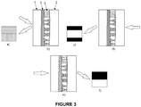
- Figure 3 shows the operating principle of a device identical to those of Figures 1 and 2 , except in this case only one of the holographic elements has been metallized. The other element is used exclusively for aligning the dichroic dye-doped LCP mixture.
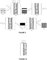
- Figure 4 shows the operating principle of a device whose holographic elements have been selectively metallized (6 and 7); in this example, the selected regions of the device present complete metallization.
- Figures 4b, 4d, 4e and 4g correspond to the same central vertical cross-section.
- Figures 4a and 4h show the image that would be seen in reflection if it is observed from the left and right side respectively.
- Figures 4c and 4f show the image that would be seen in transmission if it is observed from the left and right side respectively, illuminating with polarized light from the opposite side in each case.
- Figure 5 shows the operating principle of a device identical to that of Figure 4 , except in this case only one of the holographic elements has been metallized. The other element is used exclusively for aligning the dichroic dye-doped LCP mixture.
- Figure 6 shows the operating principle of a device identical to those of Figures 1 and 2 , except for the production process. These devices have a central structure (5) (LCP and dichroic dye) produced between two substrates, from which it is subsequently removed.
- the substrates can be rigid or flexible, for one or more uses. Partial metallization of the LCP structure can be performed before or after removing it from the substrates.
- Figure 7 shows the operating principle of a device identical to that of Figure 4 , except for the production process.
- These devices have a central structure (5) (LCP and dichroic dye) produced between two substrates, from which it is subsequently removed.
- the substrates can be rigid or flexible, for one or more uses. Partial metallization of the LCP structure can be performed before or after removing it from the substrates.
- Figure 8 shows the operating principle of a device similar to that of Figure 7 , except in this case only one surface has been metallized. It is also possible to create a structure such as the one shown in Figure 6 with a single metallized surface.
- Figures 9 to 13 show examples of devices whose production process is different.
- a polymerizable liquid crystal layer with various latent images on each face is produced. Confinement plates inducing an alignment pattern on the dichroic dye-doped polymerizable liquid crystal are used in this process.
- the resulting sheet shows two or more latent images when it is illuminated with polarized light on any of its sides, or when it is observed through a polarizer.
- the use of the polarizer is not actually required: the device works with partially polarized light, such as light originated from a grazing reflection of a dielectric surface (a shiny floor, table). Polarization component decompensation derived from the proximity of the Brewster angle is enough to show the effect.
- the result is a thin and flexible sheet containing a set of images.
- the sheet appears colored, transparent and uniform when it is illuminated with natural light. However, when it is illuminated with completely or partially polarized light, a series of images emerges. The series is determined by the face of the device where the light impinges. If the sheet is slightly rotated, a second set of images appears. Different images also appear when the sheet is illuminated on the opposite side.
- the starting material is a mixture of polymerizable liquid crystal doped with at least one dichroic dye. Confinement plates are used. An alignment pattern with various orientations is induced on the inner face of each plate.
- the alignment directions are parallel to the plane of the confinement plates.
- the sheet containing the latent images is obtained in several steps that are summarized below: first, the dye-doped liquid crystal is introduced between the confinement plates. The plates orient the liquid crystal (and therefore the dye) according to the chosen pattern. Second, the liquid crystal is polymerized to permanently fix the orientation pattern. The polymerized liquid crystal sheet is removed from the confinement sandwich. The end result is a polymerized liquid crystal sheet containing alignment information, where the final transparent sheet will show one or more images when a polarized light source, a partially polarized light source, or a polarizer is used. If the alignment pattern of each confinement plate is different, a different set of images will appear depending on the face that is oriented towards the polarized light source or the polarizer.
- the liquid crystal can be doped with one or more dyes.
- the orientation of the liquid crystal, and accordingly the dye, is determined by conditioning the inner surfaces of the confinement plates while producing the sheet.
- Glass plates are normally used as substrates in the production of conventional liquid crystal displays; in this invention, those plates are replaced with confinement plates.
- the confinement plates can be produced in any opaque or transparent material, since they are used only during the production process and are subsequently removed.
- Another advantageous characteristic of the present invention relates to variations in the liquid crystal orientation within the plane of the confinement plates. According to different embodiments of the invention, the orientations are achieved using several methods:
- liquid crystal molecules are always oriented parallel to the plane of the confinement plates, although their specific orientation within the plane varies in the different regions of the surface, such that some areas may become lighter or darker when they are illuminated with polarized light.
- Several independent images can be obtained on each side of the doped liquid crystal sheet. The variation of orientation in the alignment direction allows to define a grayscale or even color images.
- Liquid crystal polymerization allows the sheet, after being removed from the confinement plates, to be used independently in many applications: the latent images are already defined.
- Figure 9 shows a device whose operating principle is identical to that of the devices of Figures 1 and 2 .
- the reflective images that are obtained on the sheets adhered to the dichroic dye-doped LCP layer are different from the images generated by transmission on the LCP sheet itself. This does not depend on the method used for creating the flexible sheet.
- Figure 10 shows the operating principle of a device similar to that of Figure 9 , except in this case a single holographic element has been adhered to one of the surfaces.
- Figure 11 shows a device whose operating principle is identical to that of Figure 9 , in which the LCP is confined between two substrates (7 and 8) covered with alignment layers (9 and 10). In this case, the LCP is not removed from between the confinement substrates but are left there, forming part of the final structure of the device.
- Figure 12 shows the operating principle of a device similar to that of Figure 11 , except in this case a single holographic element has been adhered to one of the surfaces.
- Figure 13 shows a device whose operating principle is identical to that of Figure 4 .
- the reflective images that are obtained on the sheets adhered to the dichroic dye-doped LCP layer are different from the images generated by transmission on the LCP sheet itself. This does not depend on the method used for creating the flexible sheet.
- the present invention is directly applicable as a feature for document security against banknote counterfeiting, or in the authentication of documents, credit cards, checks, packages or any element whose intrinsic value makes its verification thereof advisable.
- the verification is performed in transmissive mode, observing with polarized light the pattern of dark and light regions that is formed, which depends exclusively on the orientation of the liquid crystal and the dichroic dye on the entrance surface. If the dichroic dye is aligned parallel to the polarization, light will be absorbed, obtaining a dark state. If the dye is located perpendicular to the polarization, light will not be absorbed, obtaining a clear state. If the faces of entry and exit are switched, the dark and light regions produced will depend on the orientation of the dye on the other side.
- any image can be induced by forcing the alignment of the corresponding regions on one of the sides.
- the other side may contain a different image, independent of the preceding one.
- the effect is observed by keeping the polarization fixed and flipping over the device, placing the opposite side of the film in front of the polarized light.
- the effect can be observed by keeping the cell fixed and placing a polarizer in front of or behind the sheet.
- a polarized light source or a polarizer is not strictly necessary in order to see the effect.
- the effect is also seen when the sample is illuminated with partially polarized light, for example, the grazing reflection from a dielectric surface such as a polished floor or a table. This favors the massive implementation of the invention as a security element in labels or banknotes, for example.
- the images are observed in reflection with natural light and without requiring any additional tool.
Landscapes
- Physics & Mathematics (AREA)
- General Physics & Mathematics (AREA)
- Nonlinear Science (AREA)
- Optics & Photonics (AREA)
- Crystallography & Structural Chemistry (AREA)
- Chemical & Material Sciences (AREA)
- Health & Medical Sciences (AREA)
- Toxicology (AREA)
- General Health & Medical Sciences (AREA)
- Engineering & Computer Science (AREA)
- Manufacturing & Machinery (AREA)
- Polarising Elements (AREA)
- Liquid Crystal (AREA)
- Diffracting Gratings Or Hologram Optical Elements (AREA)
Applications Claiming Priority (1)
| Application Number | Priority Date | Filing Date | Title |
|---|---|---|---|
| PCT/ES2015/070540 WO2017009494A1 (fr) | 2015-07-10 | 2015-07-10 | Procédé et dispositif pour sécuriser des documents par génération de multiples images latentes réflexives et transmissives |
Publications (2)
| Publication Number | Publication Date |
|---|---|
| EP3321092A1 true EP3321092A1 (fr) | 2018-05-16 |
| EP3321092A4 EP3321092A4 (fr) | 2019-02-27 |
Family
ID=57757728
Family Applications (1)
| Application Number | Title | Priority Date | Filing Date |
|---|---|---|---|
| EP15898184.5A Withdrawn EP3321092A4 (fr) | 2015-07-10 | 2015-07-10 | Procédé et dispositif pour sécuriser des documents par génération de multiples images latentes réflexives et transmissives |
Country Status (5)
| Country | Link |
|---|---|
| US (2) | US10800202B2 (fr) |
| EP (1) | EP3321092A4 (fr) |
| CN (1) | CN107921803B (fr) |
| AU (2) | AU2015402332B2 (fr) |
| WO (1) | WO2017009494A1 (fr) |
Cited By (3)
| Publication number | Priority date | Publication date | Assignee | Title |
|---|---|---|---|---|
| WO2021123177A1 (fr) * | 2019-12-20 | 2021-06-24 | Oberthur Fiduciaire Sas | Structure optique a effet de relief |
| EP4129709A1 (fr) * | 2021-08-04 | 2023-02-08 | Giesecke+Devrient Currency Technology GmbH | Produit semi-fini, élément de sécurité, procédés de production et document de valeur |
| RU2833160C1 (ru) * | 2019-12-20 | 2025-01-14 | Обертюр Фидюсьер Сас | Оптическая структура с эффектом рельефа, защитный элемент, содержащий оптическую структуру, защищенный документ, содержащий оптическую структуру, способ изготовления оптической структуры, способ аутентификации защищенного документа |
Families Citing this family (5)
| Publication number | Priority date | Publication date | Assignee | Title |
|---|---|---|---|---|
| EP3706086A4 (fr) | 2017-10-31 | 2021-07-21 | Alise Devices, S.L. | Procédé de fabrication d'éléments optiques de sécurité documentaire personnalisés et élément ainsi obtenu |
| DE102018004062A1 (de) * | 2018-05-18 | 2019-11-21 | Giesecke+Devrient Currency Technology Gmbh | Sicherheitselement mit Mikroreflektoren |
| WO2020004155A1 (fr) * | 2018-06-29 | 2020-01-02 | 日本ゼオン株式会社 | Support d'identification, procédé de détermination d'authenticité et article associé |
| JP2022502283A (ja) * | 2018-09-24 | 2022-01-11 | オーファウデー キネグラム アーゲー | 光学可変エレメント、セキュリティ文書、光学可変エレメントの製造方法、セキュリティ文書の製造方法 |
| US11250304B1 (en) * | 2020-07-23 | 2022-02-15 | Bank Of America Corporation | Payment card with light-based signature |
Family Cites Families (24)
| Publication number | Priority date | Publication date | Assignee | Title |
|---|---|---|---|---|
| JPH091963A (ja) * | 1995-06-15 | 1997-01-07 | Dainippon Printing Co Ltd | 可逆表示可能な転写箔及び可逆表示可能な記録媒体 |
| CN1163765C (zh) * | 1997-05-09 | 2004-08-25 | 罗利克有限公司 | 光学元件和包含它的防伪或防拷贝元器件 |
| JP2002127647A (ja) * | 2000-10-19 | 2002-05-08 | Nhk Spring Co Ltd | 対象物の識別媒体及びその製造方法 |
| JP2003231380A (ja) * | 2002-02-12 | 2003-08-19 | Nhk Spring Co Ltd | 対象物の識別媒体及び識別方法 |
| EP1452338A1 (fr) | 2003-02-28 | 2004-09-01 | Eidgenössische Technische Hochschule (ETH) | Caractéristiques de sécurité dichroiques à motifs |
| DE10318157A1 (de) * | 2003-04-17 | 2004-11-11 | Leonhard Kurz Gmbh & Co. Kg | Folie und optisches Sicherungselement |
| JP2005195965A (ja) * | 2004-01-08 | 2005-07-21 | Sharp Corp | ホログラム素子、その製造方法、電子光学部品 |
| GB0401060D0 (en) | 2004-01-19 | 2004-02-18 | Ezra David | Optical devices |
| DE102004018702B4 (de) * | 2004-04-17 | 2006-05-24 | Leonhard Kurz Gmbh & Co. Kg | Folie mit Polymerschicht |
| WO2006005149A2 (fr) | 2005-03-15 | 2006-01-19 | A.T.B. Latent Export Import Ltd. | Procede de production d'une couche polymere a image polarisee latente |
| JP2008139718A (ja) * | 2006-12-05 | 2008-06-19 | Dainippon Printing Co Ltd | ホログラムラベル |
| JP2008139717A (ja) * | 2006-12-05 | 2008-06-19 | Dainippon Printing Co Ltd | ホログラムラベル |
| WO2008110316A1 (fr) | 2007-03-13 | 2008-09-18 | Technische Universitei Eindhoven | Dispositif de sécurité de diffusion sélective de polarisation et son procédé de fabrication |
| DE102007019522A1 (de) | 2007-04-25 | 2008-10-30 | Giesecke & Devrient Gmbh | Durchsichtssicherheitselement |
| ES2337010B8 (es) * | 2009-12-01 | 2014-10-24 | Universidad Politécnica de Madrid | Procedimiento y dispositivo de seguridad documental por generacion de imagenes multiples |
| JP5882566B2 (ja) * | 2010-07-09 | 2016-03-09 | 富士フイルム株式会社 | 印刷および複屈折パターンを有する偽造防止媒体 |
| JP5736840B2 (ja) * | 2011-02-28 | 2015-06-17 | 凸版印刷株式会社 | 偽造防止媒体 |
| EP2543521B1 (fr) | 2011-07-07 | 2015-09-23 | European Central Bank | Document de sécurité et procédé de protection d'un document de sécurité contre la falsification et pour l'authentification du document de sécurité |
| US9279927B2 (en) * | 2013-02-15 | 2016-03-08 | Opsec Security Group, Inc. | Security device having optically variable device portion and method of making the same |
| US20150360500A1 (en) | 2013-02-19 | 2015-12-17 | Innovia Security Pty Ltd | Security Device with Covert Images |
| FR3005068B1 (fr) | 2013-04-26 | 2017-05-26 | Arjowiggins Security | Element de securite comportant un hologramme en volume. |
| CN203397619U (zh) * | 2013-08-13 | 2014-01-15 | 温州市宝信科技有限公司 | 一种纹密防伪标签 |
| DE102013217291A1 (de) | 2013-08-29 | 2015-03-05 | Bundesdruckerei Gmbh | Verfahren zum dezentralen Markieren eines Sicherheitsdokuments |
| CN104851361A (zh) * | 2015-02-13 | 2015-08-19 | 厦门天马微电子有限公司 | 一种防伪标签及其制造方法 |
-
2015
- 2015-07-10 WO PCT/ES2015/070540 patent/WO2017009494A1/fr not_active Ceased
- 2015-07-10 AU AU2015402332A patent/AU2015402332B2/en not_active Ceased
- 2015-07-10 US US15/743,480 patent/US10800202B2/en not_active Expired - Fee Related
- 2015-07-10 EP EP15898184.5A patent/EP3321092A4/fr not_active Withdrawn
- 2015-07-10 CN CN201580081839.5A patent/CN107921803B/zh not_active Expired - Fee Related
-
2018
- 2018-11-01 US US16/178,280 patent/US20190070888A1/en not_active Abandoned
-
2021
- 2021-03-12 AU AU2021201592A patent/AU2021201592A1/en not_active Abandoned
Cited By (8)
| Publication number | Priority date | Publication date | Assignee | Title |
|---|---|---|---|---|
| WO2021123177A1 (fr) * | 2019-12-20 | 2021-06-24 | Oberthur Fiduciaire Sas | Structure optique a effet de relief |
| FR3105088A1 (fr) * | 2019-12-20 | 2021-06-25 | Oberthur Fiduciaire Sas | Structure optique à effet de relief |
| CN115210083A (zh) * | 2019-12-20 | 2022-10-18 | 奥贝蒂尔信托简易股份公司 | 具有浮雕效果的光学结构 |
| JP2023507487A (ja) * | 2019-12-20 | 2023-02-22 | オベルチュール フィドゥキエール サス | レリーフ効果を有する光学的構造 |
| CN115210083B (zh) * | 2019-12-20 | 2024-08-16 | 奥贝蒂尔信托简易股份公司 | 具有浮雕效果的光学结构 |
| RU2833160C1 (ru) * | 2019-12-20 | 2025-01-14 | Обертюр Фидюсьер Сас | Оптическая структура с эффектом рельефа, защитный элемент, содержащий оптическую структуру, защищенный документ, содержащий оптическую структуру, способ изготовления оптической структуры, способ аутентификации защищенного документа |
| EP4129709A1 (fr) * | 2021-08-04 | 2023-02-08 | Giesecke+Devrient Currency Technology GmbH | Produit semi-fini, élément de sécurité, procédés de production et document de valeur |
| US12189157B2 (en) | 2021-08-04 | 2025-01-07 | Giesecke+Devrient Currency Technology Gmbh | Semi-finished product, security element, methods of producing them and document of value |
Also Published As
| Publication number | Publication date |
|---|---|
| CN107921803B (zh) | 2020-04-17 |
| US20190070888A1 (en) | 2019-03-07 |
| WO2017009494A1 (fr) | 2017-01-19 |
| AU2015402332A1 (en) | 2018-02-08 |
| CN107921803A (zh) | 2018-04-17 |
| US10800202B2 (en) | 2020-10-13 |
| AU2021201592A1 (en) | 2021-04-01 |
| EP3321092A4 (fr) | 2019-02-27 |
| US20180201045A1 (en) | 2018-07-19 |
| AU2015402332B2 (en) | 2021-02-25 |
Similar Documents
| Publication | Publication Date | Title |
|---|---|---|
| US20190070888A1 (en) | Method and device for document security by generating multiple reflective and transmissive latent images | |
| US8830425B2 (en) | Optical element | |
| AU2016201177B2 (en) | Forgery-proof medium and verification method | |
| EP1129373B1 (fr) | Composant optique | |
| EP2508358B1 (fr) | Procédé et dispositif de sécurité pour des documents reposant sur la génération d'images multiples | |
| US10889141B2 (en) | Multiple hidden image security device | |
| US11021001B2 (en) | Optical device and method for achieving multiple latent images for document security | |
| AU2016267566B2 (en) | Optical security device | |
| RU2725667C1 (ru) | Оптическое защитное устройство (варианты), способ изготовления указанного устройства и способ верификации защищаемого объекта, содержащего указанное оптическое защитное устройство | |
| CN111602179B (zh) | 用于制造个性化光学文档安全元素的方法以及所获得的元素 | |
| WO2025209793A1 (fr) | Dispositif optique | |
| HK1037731B (en) | Optical component |
Legal Events
| Date | Code | Title | Description |
|---|---|---|---|
| STAA | Information on the status of an ep patent application or granted ep patent |
Free format text: STATUS: THE INTERNATIONAL PUBLICATION HAS BEEN MADE |
|
| PUAI | Public reference made under article 153(3) epc to a published international application that has entered the european phase |
Free format text: ORIGINAL CODE: 0009012 |
|
| STAA | Information on the status of an ep patent application or granted ep patent |
Free format text: STATUS: REQUEST FOR EXAMINATION WAS MADE |
|
| 17P | Request for examination filed |
Effective date: 20180111 |
|
| AK | Designated contracting states |
Kind code of ref document: A1 Designated state(s): AL AT BE BG CH CY CZ DE DK EE ES FI FR GB GR HR HU IE IS IT LI LT LU LV MC MK MT NL NO PL PT RO RS SE SI SK SM TR |
|
| AX | Request for extension of the european patent |
Extension state: BA ME |
|
| DAV | Request for validation of the european patent (deleted) | ||
| DAX | Request for extension of the european patent (deleted) | ||
| REG | Reference to a national code |
Ref country code: DE Ref legal event code: R079 Free format text: PREVIOUS MAIN CLASS: B41M0003140000 Ipc: B42D0025364000 |
|
| A4 | Supplementary search report drawn up and despatched |
Effective date: 20190128 |
|
| RIC1 | Information provided on ipc code assigned before grant |
Ipc: B42D 25/373 20140101ALI20190122BHEP Ipc: B42D 25/328 20140101ALI20190122BHEP Ipc: B42D 25/391 20140101ALI20190122BHEP Ipc: B42D 25/364 20140101AFI20190122BHEP Ipc: B42D 25/351 20140101ALI20190122BHEP Ipc: G07D 7/128 20160101ALI20190122BHEP Ipc: G02F 1/00 20060101ALI20190122BHEP Ipc: B41M 3/14 20060101ALI20190122BHEP Ipc: G02B 5/30 20060101ALI20190122BHEP Ipc: G07D 7/121 20160101ALI20190122BHEP Ipc: G02F 1/13 20060101ALI20190122BHEP |
|
| STAA | Information on the status of an ep patent application or granted ep patent |
Free format text: STATUS: EXAMINATION IS IN PROGRESS |
|
| 17Q | First examination report despatched |
Effective date: 20191106 |
|
| GRAP | Despatch of communication of intention to grant a patent |
Free format text: ORIGINAL CODE: EPIDOSNIGR1 |
|
| STAA | Information on the status of an ep patent application or granted ep patent |
Free format text: STATUS: GRANT OF PATENT IS INTENDED |
|
| INTG | Intention to grant announced |
Effective date: 20220630 |
|
| STAA | Information on the status of an ep patent application or granted ep patent |
Free format text: STATUS: THE APPLICATION IS DEEMED TO BE WITHDRAWN |
|
| 18D | Application deemed to be withdrawn |
Effective date: 20221111 |