EP3321098A1 - Structure de support non pneumatique - Google Patents
Structure de support non pneumatique Download PDFInfo
- Publication number
- EP3321098A1 EP3321098A1 EP17199837.0A EP17199837A EP3321098A1 EP 3321098 A1 EP3321098 A1 EP 3321098A1 EP 17199837 A EP17199837 A EP 17199837A EP 3321098 A1 EP3321098 A1 EP 3321098A1
- Authority
- EP
- European Patent Office
- Prior art keywords
- spoke structure
- set forth
- cavities
- inner central
- central rim
- Prior art date
- Legal status (The legal status is an assumption and is not a legal conclusion. Google has not performed a legal analysis and makes no representation as to the accuracy of the status listed.)
- Withdrawn
Links
- 238000000034 method Methods 0.000 claims description 16
- 239000002861 polymer material Substances 0.000 claims description 8
- 230000003014 reinforcing effect Effects 0.000 claims description 8
- 230000004323 axial length Effects 0.000 claims description 7
- 229920001971 elastomer Polymers 0.000 claims description 7
- 239000000463 material Substances 0.000 claims description 7
- 239000005060 rubber Substances 0.000 claims description 7
- 229920000642 polymer Polymers 0.000 description 8
- 230000002787 reinforcement Effects 0.000 description 8
- 239000002131 composite material Substances 0.000 description 6
- 239000005020 polyethylene terephthalate Substances 0.000 description 6
- 229920000139 polyethylene terephthalate Polymers 0.000 description 6
- 229920000049 Carbon (fiber) Polymers 0.000 description 5
- 239000004917 carbon fiber Substances 0.000 description 5
- VNWKTOKETHGBQD-UHFFFAOYSA-N methane Chemical compound C VNWKTOKETHGBQD-UHFFFAOYSA-N 0.000 description 5
- 239000004696 Poly ether ether ketone Substances 0.000 description 4
- 229910000831 Steel Inorganic materials 0.000 description 4
- 230000000712 assembly Effects 0.000 description 4
- 238000000429 assembly Methods 0.000 description 4
- 238000010276 construction Methods 0.000 description 4
- 229920002530 polyetherether ketone Polymers 0.000 description 4
- 239000010959 steel Substances 0.000 description 4
- 229910000838 Al alloy Inorganic materials 0.000 description 2
- 229910001018 Cast iron Inorganic materials 0.000 description 2
- 229910000640 Fe alloy Inorganic materials 0.000 description 2
- 244000043261 Hevea brasiliensis Species 0.000 description 2
- FYYHWMGAXLPEAU-UHFFFAOYSA-N Magnesium Chemical compound [Mg] FYYHWMGAXLPEAU-UHFFFAOYSA-N 0.000 description 2
- 229920002292 Nylon 6 Polymers 0.000 description 2
- 229920002302 Nylon 6,6 Polymers 0.000 description 2
- 229920000297 Rayon Polymers 0.000 description 2
- 239000000853 adhesive Substances 0.000 description 2
- 230000001070 adhesive effect Effects 0.000 description 2
- XAGFODPZIPBFFR-UHFFFAOYSA-N aluminium Chemical compound [Al] XAGFODPZIPBFFR-UHFFFAOYSA-N 0.000 description 2
- 229910052782 aluminium Inorganic materials 0.000 description 2
- 239000004760 aramid Substances 0.000 description 2
- 229920003235 aromatic polyamide Polymers 0.000 description 2
- 150000001875 compounds Chemical class 0.000 description 2
- 238000004132 cross linking Methods 0.000 description 2
- 230000002708 enhancing effect Effects 0.000 description 2
- 239000003822 epoxy resin Substances 0.000 description 2
- 239000004744 fabric Substances 0.000 description 2
- 239000000835 fiber Substances 0.000 description 2
- 239000003365 glass fiber Substances 0.000 description 2
- LNEPOXFFQSENCJ-UHFFFAOYSA-N haloperidol Chemical compound C1CC(O)(C=2C=CC(Cl)=CC=2)CCN1CCCC(=O)C1=CC=C(F)C=C1 LNEPOXFFQSENCJ-UHFFFAOYSA-N 0.000 description 2
- 239000011777 magnesium Substances 0.000 description 2
- 229910052749 magnesium Inorganic materials 0.000 description 2
- 230000000116 mitigating effect Effects 0.000 description 2
- 229920003052 natural elastomer Polymers 0.000 description 2
- 229920001194 natural rubber Polymers 0.000 description 2
- 229920001568 phenolic resin Polymers 0.000 description 2
- 239000005011 phenolic resin Substances 0.000 description 2
- 229920000647 polyepoxide Polymers 0.000 description 2
- -1 polyethylene terephthalate Polymers 0.000 description 2
- 239000002964 rayon Substances 0.000 description 2
- 238000005096 rolling process Methods 0.000 description 2
- 229920001169 thermoplastic Polymers 0.000 description 2
- 239000004677 Nylon Substances 0.000 description 1
- 239000004952 Polyamide Substances 0.000 description 1
- 230000007423 decrease Effects 0.000 description 1
- 230000001419 dependent effect Effects 0.000 description 1
- 229920001778 nylon Polymers 0.000 description 1
- 239000004033 plastic Substances 0.000 description 1
- 229920003023 plastic Polymers 0.000 description 1
- 229920002647 polyamide Polymers 0.000 description 1
- 239000011208 reinforced composite material Substances 0.000 description 1
- 238000005476 soldering Methods 0.000 description 1
- 239000000725 suspension Substances 0.000 description 1
Images


Classifications
-
- B—PERFORMING OPERATIONS; TRANSPORTING
- B60—VEHICLES IN GENERAL
- B60C—VEHICLE TYRES; TYRE INFLATION; TYRE CHANGING; CONNECTING VALVES TO INFLATABLE ELASTIC BODIES IN GENERAL; DEVICES OR ARRANGEMENTS RELATED TO TYRES
- B60C7/00—Non-inflatable or solid tyres
- B60C7/10—Non-inflatable or solid tyres characterised by means for increasing resiliency
- B60C7/14—Non-inflatable or solid tyres characterised by means for increasing resiliency using springs
-
- B—PERFORMING OPERATIONS; TRANSPORTING
- B60—VEHICLES IN GENERAL
- B60C—VEHICLE TYRES; TYRE INFLATION; TYRE CHANGING; CONNECTING VALVES TO INFLATABLE ELASTIC BODIES IN GENERAL; DEVICES OR ARRANGEMENTS RELATED TO TYRES
- B60C5/00—Inflatable pneumatic tyres or inner tubes
- B60C5/20—Inflatable pneumatic tyres or inner tubes having multiple separate inflatable chambers
-
- B—PERFORMING OPERATIONS; TRANSPORTING
- B60—VEHICLES IN GENERAL
- B60B—VEHICLE WHEELS; CASTORS; AXLES FOR WHEELS OR CASTORS; INCREASING WHEEL ADHESION
- B60B1/00—Spoked wheels; Spokes thereof
- B60B1/02—Wheels with wire or other tension spokes
- B60B1/0261—Wheels with wire or other tension spokes characterised by spoke form
- B60B1/0276—Wheels with wire or other tension spokes characterised by spoke form the spoke being crooked in the middle and having double length
-
- B—PERFORMING OPERATIONS; TRANSPORTING
- B60—VEHICLES IN GENERAL
- B60B—VEHICLE WHEELS; CASTORS; AXLES FOR WHEELS OR CASTORS; INCREASING WHEEL ADHESION
- B60B9/00—Wheels of high resiliency, e.g. with conical interacting pressure-surfaces
- B60B9/26—Wheels of high resiliency, e.g. with conical interacting pressure-surfaces comprising resilient spokes
-
- B—PERFORMING OPERATIONS; TRANSPORTING
- B60—VEHICLES IN GENERAL
- B60C—VEHICLE TYRES; TYRE INFLATION; TYRE CHANGING; CONNECTING VALVES TO INFLATABLE ELASTIC BODIES IN GENERAL; DEVICES OR ARRANGEMENTS RELATED TO TYRES
- B60C7/00—Non-inflatable or solid tyres
- B60C7/10—Non-inflatable or solid tyres characterised by means for increasing resiliency
- B60C7/14—Non-inflatable or solid tyres characterised by means for increasing resiliency using springs
- B60C7/146—Non-inflatable or solid tyres characterised by means for increasing resiliency using springs extending substantially radially, e.g. like spokes
-
- B—PERFORMING OPERATIONS; TRANSPORTING
- B60—VEHICLES IN GENERAL
- B60C—VEHICLE TYRES; TYRE INFLATION; TYRE CHANGING; CONNECTING VALVES TO INFLATABLE ELASTIC BODIES IN GENERAL; DEVICES OR ARRANGEMENTS RELATED TO TYRES
- B60C7/00—Non-inflatable or solid tyres
- B60C7/10—Non-inflatable or solid tyres characterised by means for increasing resiliency
- B60C7/14—Non-inflatable or solid tyres characterised by means for increasing resiliency using springs
- B60C7/16—Non-inflatable or solid tyres characterised by means for increasing resiliency using springs of helical or flat coil form
- B60C7/18—Non-inflatable or solid tyres characterised by means for increasing resiliency using springs of helical or flat coil form disposed radially relative to wheel axis
-
- B—PERFORMING OPERATIONS; TRANSPORTING
- B60—VEHICLES IN GENERAL
- B60C—VEHICLE TYRES; TYRE INFLATION; TYRE CHANGING; CONNECTING VALVES TO INFLATABLE ELASTIC BODIES IN GENERAL; DEVICES OR ARRANGEMENTS RELATED TO TYRES
- B60C9/00—Reinforcements or ply arrangement of pneumatic tyres
- B60C9/02—Carcasses
-
- B—PERFORMING OPERATIONS; TRANSPORTING
- B60—VEHICLES IN GENERAL
- B60C—VEHICLE TYRES; TYRE INFLATION; TYRE CHANGING; CONNECTING VALVES TO INFLATABLE ELASTIC BODIES IN GENERAL; DEVICES OR ARRANGEMENTS RELATED TO TYRES
- B60C7/00—Non-inflatable or solid tyres
- B60C7/10—Non-inflatable or solid tyres characterised by means for increasing resiliency
- B60C7/107—Non-inflatable or solid tyres characterised by means for increasing resiliency comprising lateral openings
Definitions
- the present invention relates to wheel/tire assemblies, and more particularly, to non-pneumatic wheel/tire assemblies.
- Radial pneumatic tires rely on the ply reinforcement to carry and transfer the load between the rim and the belt layer. These ply cords need to be tensioned to carry the load. Tensioning of these ply cords is achieved with the pressurized air in the inner chamber of the tire. If air pressure is lost, load carrying capacity of a pneumatic tire decreases significantly. Preventing the slow or sudden air pressure loss has been a challenge for the tire makers.
- One proposed solution is to use non-pneumatic tires.
- a top loader non-pneumatic tire can perform similar to a pneumatic tire if its durability, speed rating/limit and load capacity can be increased to the levels of a pneumatic tire.
- top loader non-pneumatic tires rely on the polymeric spokes to carry the load of the vehicle. Spokes transfer the load from the rim to the shear band. Due to the characteristics of the polymeric materials used in the spokes of these tires, performance of these tires are limited. It is an object of the present invention to overcome this limitation and increase the load carrying capacity and durability of these spokes and hence the performance of the top loader non-pneumatic tire.
- the invention relates to a wheel and tire assembly for a mobile vehicle in accordance with claim 1 and to a method for non-pneumatically supporting a mobile vehicle in accordance with claim 7.
- a wheel and tire assembly for a mobile vehicle in accordance with a preferred aspect of the present invention includes an inner central rim, a flexible ring mounted on the inner central rim, and a spoke structure extending between the inner central rim and the flexible ring.
- the spoke structure defines a plurality of cavities and alternating radially extending openings disposed concentrically about the inner central rim and allowing the flexible ring to deflect under load.
- the spoke structure comprises a polymer material.
- the spoke structure comprises a homogenous polymer material.
- each cavity of the plurality of cavities has a common radial dimension.
- each cavity of the plurality of cavities has a common axial length equal to a uniform axial thickness of the spoke structure.
- the assembly further comprises a reinforcing layer interlaced circumferentially and radially about the plurality of cavities and alternating openings for further tuning the flexibility/stiffness of the structure.
- the spoke structure comprises a uniform rubber material.
- a method in accordance with a preferred aspect of the present invention non-pneumatically supports a mobile vehicle.
- the method includes the steps of: rotating an inner central rim about a horizontal axis; mounting the inner central rim on to a flexible ring; extending a spoke structure axially and radially between the inner central rim and the flexible ring; defining a plurality of axially extending cavities and alternating radially extending openings concentrically about the inner central rim; and vertically loading the flexible ring such that the flexible ring and a part of the spoke structure adjacent to the flexible ring both deflect vertically.
- the method comprises interlacing a reinforcing layer circumferentially and radially about the plurality of cavities for further tuning the flexibility/stiffness of the spoke structure.
- steps tune the flexibility/stiffness of the spoke structure and interlace a reinforcing layer circumferentially and radially about the plurality of cavities.
- another step buckles the spoke structure at a predetermined load on the spoke structure.
- a conventional wheel/tire assembly such as that described in US-A-2004/0069385 , has an outer ring, such as a shear band, flexibly connected to a central hub by means of lightweight composite springs.
- the springs may be plates fixed to the ring and to the hub.
- the hub may contain a speed reduction gear unit and/or an electric motor and may have a suspension mechanism for connecting a vehicle chassis to each wheel.
- the ring may be constructed from a flexible composite material, such as carbon fiber reinforced nylon material and have twin rubber tires and a plurality of circumferentially spaced-apart radial cleats which engage the ground and provide improved traction.
- the hub may also be formed from a carbon fiber reinforced composite material.
- Another conventional wheel may have a rubber strip with a molded tread bonded to a composite ring for improved grip.
- the springs interconnecting the ring and hub may be S-shaped lightweight composite springs.
- another conventional wheel/tire assembly 40 may be formed from a lightweight composite material, such as carbon fiber reinforced polyamide.
- the assembly 40 may have a cylindrical central hub 41 and a circular outer flexible rim 42 mounted on the central hub 41 by an endless looped spring band 43 extending between the central hub and the circular rim 42.
- Six radial loops 44 may be defined by the spring band 43.
- the spring band 43 may be attached to the central hub 41 and to the circular rim 42 by any suitable means, such as adhesion, cohesion, soldering and/or mechanical fixing by means of bolts, rivets, and/or clamps.
- an example wheel/tire assembly 140 in accordance with the present invention is preferably formed from a lightweight polymer material, such as, for example, a standard tire rubber compound, a thermoplastic polymer, polyethylene terephthalate (PET), polyether ether ketone (PEEK), a cross-linking polymer like natural rubber, synthetic rubber-like polymers, epoxy resins, and/or phenolic resins.
- the assembly 140 has an inner central rim 141, such as an automobile wheel, and a circular outer flexible ring 142, which preferably includes a shear band and tread structure, mounted on the inner central rim 141 by a continuous cord/fabric reinforced spoke structure 110 extending between the inner central rim and the outer ring.
- the spoke structure 110 preferably defines a plurality of cavities 111 disposed concentrically about the inner central rim 141 allowing the spoke structure to deflect under load thereby defining a suitable balance between flexibility for ride comfort and traction within a footprint of the assembly 140 and stiffness for vehicle handling, low rolling resistance, and low heat build-up within the spoke structure.
- the cavities 111 of the spoke structure 110 further define openings for arms 147 of the inner central rim 141 to extend therethrough and secure the spoke structure to the to the inner central rim.
- the arms 147 preferably engage portions 157 of the spoke structure 110 in a mechanical interlocking arrangement.
- the inner central rim 141 preferably further include plates 149 that, along with the arms 147 may sandwich the portions 157 of the spoke structure 110 and create a further frictional and/or adhesive securement between the inner central rim 141 and the spoke structure.
- the spoke structure 110 may comprise a homogenous or heterogeneous polymer and/or a filled polymer.
- the spokes 115 of the spoke structure 110 may be curved inwardly or outwardly for mitigating or enhancing buckling of the spokes.
- the spokes 115 preferably include one or more reinforcing layers 119.
- the layer(s) 119 may be constructed of single end dipped cords, conventional pneumatic tire ply/cord arrangements, short fibers, and/or polymeric film. Further, these constructions may be PET, nylon 6, nylon 6,6, rayon, steel, glass fibers, carbon fiber, aramid, and/or a hybrid construction of these materials.
- the cords may be from 400 denier to 9000 denier.
- the polymeric film may be from 0.1 mm to 2.0 mm thick.
- the spokes 115 may be oriented at angle between 0 degrees and 90 degrees. Preferably, the spokes 115 are continuously reinforced across their entire axial length. Continuous reinforcement layer(s) 119 may extend radially outward to multiple locations adjacent to a shear band at the outer flexible ring 142.
- Each cavity 111 preferably has a common cross sectional profile about the axis of rotation of the assembly. Further, each cavity 111 preferably has a common axial length equal to a uniform axial thickness of the spoke structure 110. Preferably, each cavity 111 is be curvedly shaped to prevent "pinch" points on the reinforcement layer(s) 119 and mitigate compressive stress concentrations on the reinforcement layer(s). The number of cavities 111 may be between 2 and 60 for large scale assemblies 140.
- the inner central rim 141 may include steel, cast iron, aluminum, aluminum alloys, magnesium allows, and/or iron alloys.
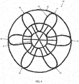
- an example wheel/tire assembly 240 in accordance with the present invention is preferably formed from a lightweight polymer material, such as, for example, a standard tire rubber compound, a thermoplastic polymer, polyethylene terephthalate (PET), polyether ether ketone (PEEK), a cross-linking polymer like natural rubber, synthetic rubber-like polymers, epoxy resins, and/or phenolic resins.
- the assembly 240 has an inner central rim 241, such as an automobile wheel, and a circular outer flexible ring 242, which preferably includes a shear band and tread structure, mounted on the inner central rim 241 by a continuous cord/fabric reinforced spoke structure 210 extending between the inner central rim and the outer ring.
- the spoke structure 210 preferably defines a plurality of alternating cavities 211 and inlet openings 212 disposed concentrically about the inner central rim 241 allowing the spoke structure 210 to deflect under load thereby defining a suitable balance between flexibility for ride comfort and traction within a footprint of the assembly 240 and stiffness for vehicle handling, low rolling resistance, and low heat build-up within the spoke structure.
- the cavities 211 of the spoke structure 210 preferably further define openings for arms 247 of the inner central rim 241 to extend therethrough and secure the spoke structure to the inner central rim.
- the arms 247 preferably engage portions 257 of the spoke structure 210 in a mechanical interlocking arrangement.
- the inner central rim 241 preferably further include plates 249 that, along with the arms 247 may sandwich the portions 257 of the spoke structure 210 and create a further frictional and/or adhesive securement between the inner central rim 241 and the spoke structure.
- the spoke structure 210 may comprise a homogenous or heterogeneous polymer and/or a filled polymer.
- Spokes 215 of the spoke structure 210 may be curved inwardly or outwardly for mitigating or enhancing buckling of the spokes.
- the spokes 215 preferably include one or more reinforcing layers 219.
- the layer(s) 219 may be constructed of single end dipped cords, conventional pneumatic tire ply/cord arrangements, short fibers, and/or polymeric film. Further, these constructions may be PET, nylon 6, nylon 6,6, rayon, steel, glass fibers, carbon fiber, aramid, and/or a hybrid construction of these materials.
- the cords may be from 400 denier to 9000 denier.
- the polymeric film may be from 0.1 mm to 2.0 mm thick.
- the reinforcement in the spokes 115 may be oriented at angle between 0 degrees and 90 degrees.
- the spokes 215 are preferably continuously reinforced across their entire axial length. Preferably, continuous reinforcement layer(s) 219 extend radially outward to multiple locations adjacent to a shear band at the outer flexible ring 242.
- Each cavity 211 and inlet opening 212 preferably have a common cross sectional profile about the axis of rotation of the assembly. Further, each cavity 211 and inlet opening 212 preferably have a common axial length equal to a uniform axial thickness of the spoke structure 210. Each cavity 211 may be curvedly shaped to prevent "pinch" points on the reinforcement layer(s) 219 and mitigate compressive stress concentrations on the reinforcement layer(s). The number of cavities 211 may be between 2 and 60 for large scale assemblies 240.
- point(s) 231 represent point(s) on the spoke structure 210 nearest the axis of rotation 201 of the wheel/tire assembly 241.
- Point(s) 232 on the spoke structure represent point(s) in the inlet openings 212 farthest from the axis 201 of rotation of the assembly 241.
- Line(s) 233 represent a straight line connecting one point 231 with an adjacent point 232.
- Line(s) 234 represent line(s) perpendicular to radial line(s) extending through the point(s) 231.
- the angle between line(s) 233 and adjacent line(s) 234 is preferably between -45 degrees and 90 degrees.
- the inner central rim 241 may include steel, cast iron, aluminum, aluminum alloys, magnesium allows, iron alloys, plastics, and/or composites.
- the spoke structure 210 may further have additional cavities 248 for further adjusting the flexibility of the spoke structure.
Landscapes
- Engineering & Computer Science (AREA)
- Mechanical Engineering (AREA)
- Tires In General (AREA)
Applications Claiming Priority (1)
| Application Number | Priority Date | Filing Date | Title |
|---|---|---|---|
| US15/351,672 US10040317B2 (en) | 2016-11-15 | 2016-11-15 | Non-pneumatic support structure |
Publications (1)
| Publication Number | Publication Date |
|---|---|
| EP3321098A1 true EP3321098A1 (fr) | 2018-05-16 |
Family
ID=60244965
Family Applications (1)
| Application Number | Title | Priority Date | Filing Date |
|---|---|---|---|
| EP17199837.0A Withdrawn EP3321098A1 (fr) | 2016-11-15 | 2017-11-03 | Structure de support non pneumatique |
Country Status (6)
| Country | Link |
|---|---|
| US (1) | US10040317B2 (fr) |
| EP (1) | EP3321098A1 (fr) |
| JP (1) | JP2018087001A (fr) |
| KR (1) | KR20180054484A (fr) |
| CN (1) | CN108068549B (fr) |
| BR (1) | BR102017024490A2 (fr) |
Cited By (5)
| Publication number | Priority date | Publication date | Assignee | Title |
|---|---|---|---|---|
| KR20200067650A (ko) * | 2018-12-04 | 2020-06-12 | 현대자동차주식회사 | 타이어 공기압 감시 장치 및 방법 |
| JP2021031057A (ja) * | 2019-08-29 | 2021-03-01 | ザ・グッドイヤー・タイヤ・アンド・ラバー・カンパニー | 可撓ループ状スポークを有する非空気入りタイヤとその形成方法 |
| EP3785931A1 (fr) * | 2019-08-29 | 2021-03-03 | The Goodyear Tire & Rubber Company | Pneu non pneumatique de boucleur |
| US20220194129A1 (en) * | 2020-12-21 | 2022-06-23 | The Goodyear Tire & Rubber Company | Non-pneumatic tire and wheel assembly with reinforced spoke structure |
| JP2023508550A (ja) * | 2019-12-30 | 2023-03-02 | ブリヂストン アメリカズ タイヤ オペレーションズ、 エルエルシー | 補強された支持構造体を有する非空気圧式タイヤ及びその作製方法 |
Families Citing this family (12)
| Publication number | Priority date | Publication date | Assignee | Title |
|---|---|---|---|---|
| US10150334B2 (en) * | 2016-11-15 | 2018-12-11 | The Goodyear Tire & Rubber Company | Non-pneumatic support structure |
| US10207544B2 (en) * | 2016-11-15 | 2019-02-19 | The Goodyear Tire & Rubber Company | Wheel for a support structure |
| US10286725B2 (en) | 2017-03-22 | 2019-05-14 | The Goodyear Tire & Rubber Company | Non-pneumatic support structure |
| US11273673B2 (en) | 2019-10-25 | 2022-03-15 | The Goodyear Tire & Rubber Company | Modular non-pneumatic support structure |
| US11318791B2 (en) | 2019-11-15 | 2022-05-03 | The Goodyear Tire & Rubber Company | Wheel for a support structure |
| US11142022B2 (en) | 2019-11-15 | 2021-10-12 | The Goodyear Tire & Rubber Company | Support structure |
| US11124024B2 (en) | 2019-11-25 | 2021-09-21 | The Goodyear Tire & Rubber Company | Support structure |
| BR112022011969A2 (pt) * | 2019-12-16 | 2022-09-06 | Michelin & Cie | Raio de pneu não pneumático com corpo de junta elastomérica aprimorada |
| EP3871902B1 (fr) | 2020-02-28 | 2023-07-19 | The Goodyear Tire & Rubber Company | Pneu non pneumatique |
| US11697307B2 (en) * | 2020-12-04 | 2023-07-11 | The Goodyear Tire & Rubber Company | Wheel for a support structure |
| EP4415977A4 (fr) * | 2021-10-12 | 2025-08-27 | Bridgestone Americas Tire Operations Llc | Pneu non pneumatique ayant une structure de support renforcée et son procédé de fabrication |
| CN114953849B (zh) * | 2022-06-20 | 2023-07-25 | 南京航空航天大学 | 一种仿生竹节虫胫骨空心结构轮辐式非充气车轮 |
Citations (10)
| Publication number | Priority date | Publication date | Assignee | Title |
|---|---|---|---|---|
| US624315A (en) * | 1899-05-02 | John f | ||
| GB2177355A (en) * | 1985-03-01 | 1987-01-21 | Nigel Connor | Vehicle tyre |
| US20040069385A1 (en) | 2002-07-01 | 2004-04-15 | Sean Timoney | Wheel |
| US20060144488A1 (en) * | 2005-01-04 | 2006-07-06 | Vannan Frederick F | Airless tire |
| JP2009286208A (ja) * | 2008-05-28 | 2009-12-10 | Yokohama Rubber Co Ltd:The | 非空気式タイヤ |
| US20100200131A1 (en) * | 2007-07-31 | 2010-08-12 | Toyo Tire & Rubber Co., Ltd. | Non-pneumatic tire and its manufacturing method |
| WO2011025491A1 (fr) * | 2009-08-28 | 2011-03-03 | Michelin Recherche Et Technique, S.A. | Ensemble roue non pneumatique avec moyeu amovible |
| JP2011219009A (ja) * | 2010-04-12 | 2011-11-04 | Toyo Tire & Rubber Co Ltd | 非空気圧タイヤ及びその製造方法 |
| WO2012160534A1 (fr) * | 2011-05-24 | 2012-11-29 | Pieter Johannes Labuschagne | Pneu sans air pour véhicules |
| WO2016123180A2 (fr) * | 2015-01-27 | 2016-08-04 | Mtd Products Inc | Ensembles roues dotés de pneus non pneumatiques |
Family Cites Families (23)
| Publication number | Priority date | Publication date | Assignee | Title |
|---|---|---|---|---|
| US482175A (en) | 1892-09-06 | George hollafolla | ||
| US479255A (en) | 1892-07-19 | boyd dunlop | ||
| US1002003A (en) | 1910-07-23 | 1911-08-29 | Christian J Simonson | Steel tire. |
| US1233722A (en) | 1917-01-03 | 1917-07-17 | Frederick Kemppel | Resilient wheel. |
| US1389285A (en) | 1920-03-29 | 1921-08-30 | August W Althoff | Vehicle-wheel |
| US1451517A (en) | 1922-02-27 | 1923-04-10 | William H Smith | Spring wheel |
| US1930764A (en) | 1931-11-05 | 1933-10-17 | Wingfoot Corp | Pneumatic tire and method of making same |
| US3493027A (en) | 1966-05-20 | 1970-02-03 | Nasa | Deformable vehicle wheel |
| US4226273A (en) | 1978-06-30 | 1980-10-07 | The Goodyear Tire & Rubber Company | Nonpneumatic tire and rim assembly |
| US4235270A (en) | 1978-06-30 | 1980-11-25 | The Goodyear Tire & Rubber Company | Tire with supporting and cushioning walls |
| US4602823A (en) | 1981-08-18 | 1986-07-29 | Berg Charles A | Portable collapsible wheels |
| CA2043082A1 (fr) | 1991-02-27 | 1992-08-28 | James Edward Duddey | Pneu de secours sans chambre |
| US5800643A (en) | 1996-04-26 | 1998-09-01 | Inner Tire Corporation | Pneumatic inner tire |
| US6260598B1 (en) | 1997-07-11 | 2001-07-17 | Sumitomo Rubber Industries, Ltd. | Pneumatic tire with looped tread-sidewall reinforcement |
| US6068721A (en) | 1998-03-27 | 2000-05-30 | The Goodyear Tire & Rubber Company | Method of fabricating a tire having a geodesic ply |
| WO2009005945A1 (fr) | 2007-06-29 | 2009-01-08 | Societe De Technologie Michelin | Bande de cisaillement élastique à éléments cylindriques |
| FR2928865B1 (fr) | 2008-03-19 | 2010-03-19 | Michelin Soc Tech | Roue elastique non pneumatique |
| KR101378436B1 (ko) * | 2012-06-27 | 2014-03-27 | 한국타이어 주식회사 | 에어리스 타이어 |
| WO2016100017A1 (fr) * | 2014-12-18 | 2016-06-23 | Bridgestone Americas Tire Operations, Llc | Pneu à rayons arciformes |
| USD792332S1 (en) * | 2015-06-03 | 2017-07-18 | Mtd Products Inc | Non-pneumatic tire |
| US20160214435A1 (en) * | 2015-01-27 | 2016-07-28 | Mtd Products Inc | Wheel assemblies with non-pneumatic tires |
| US10899169B2 (en) * | 2015-01-27 | 2021-01-26 | Mtd Products Inc | Wheel assemblies with non-pneumatic tires |
| USD784917S1 (en) * | 2015-06-03 | 2017-04-25 | Mtd Products Inc | Non-pneumatic tire |
-
2016
- 2016-11-15 US US15/351,672 patent/US10040317B2/en active Active
-
2017
- 2017-11-03 EP EP17199837.0A patent/EP3321098A1/fr not_active Withdrawn
- 2017-11-13 KR KR1020170150734A patent/KR20180054484A/ko not_active Ceased
- 2017-11-14 BR BR102017024490-3A patent/BR102017024490A2/pt not_active IP Right Cessation
- 2017-11-15 CN CN201711129502.4A patent/CN108068549B/zh not_active Expired - Fee Related
- 2017-11-15 JP JP2017219939A patent/JP2018087001A/ja active Pending
Patent Citations (10)
| Publication number | Priority date | Publication date | Assignee | Title |
|---|---|---|---|---|
| US624315A (en) * | 1899-05-02 | John f | ||
| GB2177355A (en) * | 1985-03-01 | 1987-01-21 | Nigel Connor | Vehicle tyre |
| US20040069385A1 (en) | 2002-07-01 | 2004-04-15 | Sean Timoney | Wheel |
| US20060144488A1 (en) * | 2005-01-04 | 2006-07-06 | Vannan Frederick F | Airless tire |
| US20100200131A1 (en) * | 2007-07-31 | 2010-08-12 | Toyo Tire & Rubber Co., Ltd. | Non-pneumatic tire and its manufacturing method |
| JP2009286208A (ja) * | 2008-05-28 | 2009-12-10 | Yokohama Rubber Co Ltd:The | 非空気式タイヤ |
| WO2011025491A1 (fr) * | 2009-08-28 | 2011-03-03 | Michelin Recherche Et Technique, S.A. | Ensemble roue non pneumatique avec moyeu amovible |
| JP2011219009A (ja) * | 2010-04-12 | 2011-11-04 | Toyo Tire & Rubber Co Ltd | 非空気圧タイヤ及びその製造方法 |
| WO2012160534A1 (fr) * | 2011-05-24 | 2012-11-29 | Pieter Johannes Labuschagne | Pneu sans air pour véhicules |
| WO2016123180A2 (fr) * | 2015-01-27 | 2016-08-04 | Mtd Products Inc | Ensembles roues dotés de pneus non pneumatiques |
Cited By (8)
| Publication number | Priority date | Publication date | Assignee | Title |
|---|---|---|---|---|
| KR20200067650A (ko) * | 2018-12-04 | 2020-06-12 | 현대자동차주식회사 | 타이어 공기압 감시 장치 및 방법 |
| JP2021031057A (ja) * | 2019-08-29 | 2021-03-01 | ザ・グッドイヤー・タイヤ・アンド・ラバー・カンパニー | 可撓ループ状スポークを有する非空気入りタイヤとその形成方法 |
| EP3785933A1 (fr) * | 2019-08-29 | 2021-03-03 | The Goodyear Tire & Rubber Company | Pneu non pneumatique doté d'un rayon en boucle flexible et son procédé de formation |
| EP3785931A1 (fr) * | 2019-08-29 | 2021-03-03 | The Goodyear Tire & Rubber Company | Pneu non pneumatique de boucleur |
| JP2023508550A (ja) * | 2019-12-30 | 2023-03-02 | ブリヂストン アメリカズ タイヤ オペレーションズ、 エルエルシー | 補強された支持構造体を有する非空気圧式タイヤ及びその作製方法 |
| JP7333478B2 (ja) | 2019-12-30 | 2023-08-24 | ブリヂストン アメリカズ タイヤ オペレーションズ、 エルエルシー | 補強された支持構造体を有する非空気圧式タイヤ及びその作製方法 |
| US20220194129A1 (en) * | 2020-12-21 | 2022-06-23 | The Goodyear Tire & Rubber Company | Non-pneumatic tire and wheel assembly with reinforced spoke structure |
| EP4023461A1 (fr) * | 2020-12-21 | 2022-07-06 | The Goodyear Tire & Rubber Company | Pneu non pneumatique et ensemble roue à structure de rayon renforcé |
Also Published As
| Publication number | Publication date |
|---|---|
| CN108068549A (zh) | 2018-05-25 |
| US10040317B2 (en) | 2018-08-07 |
| BR102017024490A2 (pt) | 2018-08-14 |
| US20180134083A1 (en) | 2018-05-17 |
| KR20180054484A (ko) | 2018-05-24 |
| CN108068549B (zh) | 2020-04-17 |
| JP2018087001A (ja) | 2018-06-07 |
Similar Documents
| Publication | Publication Date | Title |
|---|---|---|
| US10040317B2 (en) | Non-pneumatic support structure | |
| US10207544B2 (en) | Wheel for a support structure | |
| EP3378676B1 (fr) | Ensemble pneu et roue ayant une structure de support non pneumatique | |
| US10406852B2 (en) | Non-pneumatic support structure | |
| US10603956B2 (en) | Wheel for a support structure | |
| US10150334B2 (en) | Non-pneumatic support structure | |
| EP3599107B1 (fr) | Roue pour une structure de support | |
| EP3321100A1 (fr) | Système et procédé de fabrication d'une structure de support non pneumatique | |
| EP4008539A2 (fr) | Système et procédé de fabrication d'une structure de support | |
| EP4008563B1 (fr) | Ensemble pneu/roue et procédé de support d'un véhicule | |
| US11584163B2 (en) | Non-pneumatic support structure | |
| EP3812168B1 (fr) | Structure et procédé de support non pneumatique modulaire | |
| EP3822092B1 (fr) | Ensemble roue pour une structure de support | |
| EP4197807B1 (fr) | Ensemble pneu/jante pour structure de support | |
| US12202219B2 (en) | System for manufacturing a support structure | |
| US11794513B2 (en) | Wheel for a support structure |
Legal Events
| Date | Code | Title | Description |
|---|---|---|---|
| PUAI | Public reference made under article 153(3) epc to a published international application that has entered the european phase |
Free format text: ORIGINAL CODE: 0009012 |
|
| AK | Designated contracting states |
Kind code of ref document: A1 Designated state(s): AL AT BE BG CH CY CZ DE DK EE ES FI FR GB GR HR HU IE IS IT LI LT LU LV MC MK MT NL NO PL PT RO RS SE SI SK SM TR |
|
| AX | Request for extension of the european patent |
Extension state: BA ME |
|
| STAA | Information on the status of an ep patent application or granted ep patent |
Free format text: STATUS: THE APPLICATION IS DEEMED TO BE WITHDRAWN |
|
| 18D | Application deemed to be withdrawn |
Effective date: 20181117 |