EP3321175A1 - Flugzeugspaltdichtung - Google Patents
Flugzeugspaltdichtung Download PDFInfo
- Publication number
- EP3321175A1 EP3321175A1 EP17201055.5A EP17201055A EP3321175A1 EP 3321175 A1 EP3321175 A1 EP 3321175A1 EP 17201055 A EP17201055 A EP 17201055A EP 3321175 A1 EP3321175 A1 EP 3321175A1
- Authority
- EP
- European Patent Office
- Prior art keywords
- gap
- seal
- gap seal
- external skin
- assembly according
- Prior art date
- Legal status (The legal status is an assumption and is not a legal conclusion. Google has not performed a legal analysis and makes no representation as to the accuracy of the status listed.)
- Withdrawn
Links
Images



Classifications
-
- F—MECHANICAL ENGINEERING; LIGHTING; HEATING; WEAPONS; BLASTING
- F16—ENGINEERING ELEMENTS AND UNITS; GENERAL MEASURES FOR PRODUCING AND MAINTAINING EFFECTIVE FUNCTIONING OF MACHINES OR INSTALLATIONS; THERMAL INSULATION IN GENERAL
- F16J—PISTONS; CYLINDERS; SEALINGS
- F16J15/00—Sealings
- F16J15/44—Free-space packings
- F16J15/447—Labyrinth packings
-
- B—PERFORMING OPERATIONS; TRANSPORTING
- B64—AIRCRAFT; AVIATION; COSMONAUTICS
- B64C—AEROPLANES; HELICOPTERS
- B64C1/00—Fuselages; Constructional features common to fuselages, wings, stabilising surfaces or the like
- B64C1/0009—Aerodynamic aspects
-
- B—PERFORMING OPERATIONS; TRANSPORTING
- B64—AIRCRAFT; AVIATION; COSMONAUTICS
- B64C—AEROPLANES; HELICOPTERS
- B64C7/00—Structures or fairings not otherwise provided for
-
- B—PERFORMING OPERATIONS; TRANSPORTING
- B64—AIRCRAFT; AVIATION; COSMONAUTICS
- B64C—AEROPLANES; HELICOPTERS
- B64C3/00—Wings
- B64C3/26—Construction, shape, or attachment of separate skins, e.g. panels
-
- B—PERFORMING OPERATIONS; TRANSPORTING
- B64—AIRCRAFT; AVIATION; COSMONAUTICS
- B64C—AEROPLANES; HELICOPTERS
- B64C1/00—Fuselages; Constructional features common to fuselages, wings, stabilising surfaces or the like
- B64C1/06—Frames; Stringers; Longerons ; Fuselage sections
- B64C1/12—Construction or attachment of skin panels
-
- B—PERFORMING OPERATIONS; TRANSPORTING
- B64—AIRCRAFT; AVIATION; COSMONAUTICS
- B64C—AEROPLANES; HELICOPTERS
- B64C3/00—Wings
- B64C3/36—Structures adapted to reduce effects of aerodynamic or other external heating
-
- B—PERFORMING OPERATIONS; TRANSPORTING
- B64—AIRCRAFT; AVIATION; COSMONAUTICS
- B64C—AEROPLANES; HELICOPTERS
- B64C9/00—Adjustable control surfaces or members, e.g. rudders
- B64C9/02—Mounting or supporting thereof
-
- F—MECHANICAL ENGINEERING; LIGHTING; HEATING; WEAPONS; BLASTING
- F16—ENGINEERING ELEMENTS AND UNITS; GENERAL MEASURES FOR PRODUCING AND MAINTAINING EFFECTIVE FUNCTIONING OF MACHINES OR INSTALLATIONS; THERMAL INSULATION IN GENERAL
- F16J—PISTONS; CYLINDERS; SEALINGS
- F16J15/00—Sealings
-
- F—MECHANICAL ENGINEERING; LIGHTING; HEATING; WEAPONS; BLASTING
- F16—ENGINEERING ELEMENTS AND UNITS; GENERAL MEASURES FOR PRODUCING AND MAINTAINING EFFECTIVE FUNCTIONING OF MACHINES OR INSTALLATIONS; THERMAL INSULATION IN GENERAL
- F16J—PISTONS; CYLINDERS; SEALINGS
- F16J15/00—Sealings
- F16J15/02—Sealings between relatively-stationary surfaces
- F16J15/06—Sealings between relatively-stationary surfaces with solid packing compressed between sealing surfaces
- F16J15/10—Sealings between relatively-stationary surfaces with solid packing compressed between sealing surfaces with non-metallic packing
- F16J15/104—Sealings between relatively-stationary surfaces with solid packing compressed between sealing surfaces with non-metallic packing characterised by structure
-
- B—PERFORMING OPERATIONS; TRANSPORTING
- B64—AIRCRAFT; AVIATION; COSMONAUTICS
- B64C—AEROPLANES; HELICOPTERS
- B64C9/00—Adjustable control surfaces or members, e.g. rudders
Definitions
- the present invention relates to a seal for sealing a gap between panels in an aircraft assembly.
- Gaps between panels which may move relative to one another are typically filled with an elastomeric seal member which can be compressed as the gap closes.
- Gaps between fixed panels i.e. panels which are not intended to be moved during operation of the aircraft
- a curable sealant such as a polysulphide sealant.
- the present invention provides an aircraft gap seal formed from a material that, when compressed in the gap width direction, does not expand in the gap depth direction.
- a first aspect of the invention provides an aircraft assembly, comprising: first and second external skin panels having opposing edge faces separated by a gap, the gap having a width in a first direction extending between the opposing edge faces and a depth in a second direction generally orthogonal to the first direction; and a gap seal arranged in the gap to at least partially fill the gap, wherein the gap seal comprises material configured such that compression of the gap seal in the first direction results in substantially no expansion of the gap seal in the second direction.
- a second related aspect of the invention provides a gap seal for an aircraft assembly comprising first and second external skin panels having opposing edge faces separated by a gap, the gap having a width in a first direction extending between the opposing edge faces and a depth in a second direction generally orthogonal to the first direction, the gap seal being configured to be arranged in the gap to at least partially fill the gap, and the gap seal comprising material configured such that compression of the gap seal in the first direction results in substantially no expansion of the gap seal in the second direction.
- Known gap seals suffer from the disadvantage that when they are highly compressed they may protrude out of the gap to form a drag-inducing aerodynamic step.
- Elastomeric seal members such as rubber gasket-type seals having an O- or D-shaped cross-section, or lip-type seals, in particular provide a compromised solution because their shape means that they are unable to completely fill the gap without such unwanted protrusion.
- Cured sealant beads also suffer from the defect that compression across the gap leads to protrusion out of the gap, and also have the disadvantage that they typically do not completely eliminate the gap in their uncompressed state, but instead provide a shallow depression in the aerodynamic surface.
- the present inventors have identified that these problems may be solved by forming a novel gap seal from a material which, when compressed in the gap width direction, does not substantially expand in the gap depth direction.
- first or second panels may comprise a fairing (i.e. a panel solely for the purpose of improving aerodynamic performance e.g. by concealing drag-inducing structure or systems), control surface, or movable panel such as an access door (e.g. landing gear bay door).
- a fairing i.e. a panel solely for the purpose of improving aerodynamic performance e.g. by concealing drag-inducing structure or systems
- control surface e.g. by concealing drag-inducing structure or systems
- movable panel such as an access door (e.g. landing gear bay door).
- the material of the gap seal has a poisson's ratio in at least the first direction equal to or less than 0.1, more preferably equal to or less than 0.06, and most preferably equal to or less than 0.05.
- Poisson's ratio is the negative ratio of transverse to axial strain, i.e. the fraction of resulting expansion divided by the fraction of applied compression.
- Elastomers which are commonly used in aircraft gap seals, typically have a poisson's ratio in the region of 0.4999.
- the material of the gap seal may comprise a grid of cells.
- Each cell may have at least third order rotational symmetry, preferably fourth, fifth or sixth order symmetry.
- the grid may comprise a lattice/array of identical cells.
- the material may comprise a substrate and each cell may comprise a uniform pattern of apertures in the substrate.
- each cell may comprise a uniform pattern of apertures in the substrate.
- the material is preferably formed from one of the following: polyurethane; polytetrafluoroethylene; an elastomer, including silicon rubber or neoprene; or cork.
- Polytetrafluoroethylene, polyurethane and elastomers all have a poisson's ratio in the region of 0.45-0.5, and therefore exhibit significant transverse expansion in response to axial compression.
- by engineering such materials so that they exhibit a low poisson's ratio (equal to or less than 0.1, more preferably equal to or less than 0.06, and most preferably equal to or less than 0.05) in at least the first direction they are suitable for the gap seal of the present invention. This may be achieved by providing the material as a foam, by forming a grid of cells from a substrate of the material, by forming a lattice of cells each comprising a plurality of interconnected arms, or in any other suitable way.
- the first and second external skin panels may be able to move relative to one another between a first configuration in which the gap seal is arranged in the gap to at least partially fill the gap and a second configuration in which the gap seal is compressed in the first direction.
- one of the first and second skin panels may comprise a panel of a movable control surface, an access door (e.g. landing gear bay door), or a panel of a folding wing assembly.
- Such embodiments may include a blade seal attached to the first or second external skin panel and extending across the width of the gap to obscure the gap in at least the second configuration.
- the blade seal thus serves to prevent pressure differences across the panels from causing the gap seal to be dislodged from the gap, e.g. by being 'blown' or 'sucked' out of the gap.
- the blade seal is preferably attached to an internal surface of the first or second skin panel.
- the blade seal is preferably configured to slide relative to the other of the first or second external skin panel, respectively, during relative movement of the first and second external skin panels. In this way, relative movement of the panels is not hindered, and the blade seal cannot transmit loads (forces) between the first and second panels.
- the gap seal is fixed (i.e. attached, fastened or otherwise secured) to the opposing edge face of a respective one of the first or second external skin panel, and is not fixed to the opposing edge face of the other of the first or second external skin panel. In this way, relative movement of the panels is not hindered, but the gap seal is retained within the gap.
- the gap seal may be fixed to the opposing edge face of the first or second external skin panel by bonding.
- the assembly may include a friction layer between the gap seal and the opposing edge face of the other of the first or second external skin panel, wherein the friction layer has a higher coefficient of friction than the gap seal.
- a respective one of the first and second external skin panels may comprise a panel of a movable control surface or an access door such as a landing gear bay door.
- the first and second external skin panels each comprise a fixed panel, i.e. a panel that is normally fixed in place during aircraft operations (e.g. ground operations, or flight operations).
- the present invention may be applied to folding wing arrangements.
- the aircraft assembly includes an inner wing section comprising the first external skin panel, and an outer wing section comprising the second external skin panel, the outer wing being pivotable relative to the inner wing between a folded configuration in which the first and second external skin panels are separated, and a flight configuration in which the gap seal is compressed in the first direction.
- the gap between panels at either side of the inner-outer wing joint can be easily, accurately and completely filled when the wing is unfolded to its flight configuration, without any additional process step.
- undesirable aerodynamic steps are also avoided.
- a third aspect of the invention provides an aircraft comprising an assembly or a gap seal according to the first or second aspects.
- Figs. 1A and 1B show plan and section views, respectively, of an aircraft panel assembly according to an embodiment of the invention.
- First 10 and second 20 panels are arranged adjacent one another so that their outer surfaces 12, 22 together form an aerodynamic surface of the aircraft.
- the first 10 and second 20 panels are supported by respective structural members 18, 28 to which they are attached by a respective row of fasteners 19, 29.
- loads are not transferred directly between the first 10 and second 20 panels, though such loads may instead be transmitted via a structural connection (not shown; e.g. a buttstrap) .
- the first 10 and second 20 panels may each comprise a fixed or movable panel, i.e. a panel that is configured to be either fixed or movable during operation of the aircraft.
- the panels may both be fixed during flight of the aircraft, or one or both of the panels may be movable during flight of the aircraft.
- the panels may each be fixed during flight, but movable during maintenance or ground manoeuvres.
- Examples of applications for an aircraft assembly according to the present invention include, but are not limited to:
- the panels 10, 20 are separated by a gap 30 which extends between opposing edge faces 14, 24 of the panels.
- the gap 30 thus has a width, w, defined as a distance between the opposing edge faces 14, 24 in a first direction (x-direction in Fig. 1 ), and a depth, d, defined as a distance between a base of the gap 30 and the aerodynamic surface in a second direction (y-direction in Fig. 1 ).
- the width, w, and depth, d may vary along the length of the gap 30 (z-direction in Fig. 1 ).
- a gap seal 40 is positioned within the gap 30 so that it substantially fills the gap.
- the gap seal 40 has a shape corresponding to that of the gap 30 such that it is elongate and has a generally rectangular cross-section.
- the gap seal 40 thus has a height generally corresponding to the depth, d, of the gap, and a width generally corresponding to the width, w, of the gap.
- the gap seal 40 may only partially fill the gap 30; for example, the width of the gap seal 40 may be less than the width, w, of the gap 30 along some or all of the length of the gap.
- the gap seal 40 thus serves to at least partially fill the gap 30 to minimise parasitic drag at the gap generated by airflow travelling over the aerodynamic surface 12,22.
- a generally planar blade seal 50 is fastened at one side to the first panel 10 via a row of fasteners 52 and extends across the full width of the gap 30 so that it lies in contact with internal surfaces 16, 26 of the first 10 and second 20 panels, and with a surface of the gap seal 40.
- the blade seal 50 is not attached to the second panel 20, and preferably has a low-friction surface finish, layer or coating at the interface with the second panel 20 to permit relative sliding between the two parts.
- the blade seal 50 has an elongate generally four-sided shape such that it obscures the gap 30 along its width and length.
- the blade seal 50 serves to prevent differential pressures between the internal and external surfaces of the panels 10, 20 from causing the gap seal 40 to be dislodged from the gap 30. It is only attached to one of the panels 10, 20 for two reasons: in embodiments in which there is significant relative movement between the panels 10, 20, to permit such relative movement; and in embodiments with only small, or negligible, amounts of relative movement between the panels, to prevent any load transfer between the panels in the event of relative movement between the panels 10, 20.
- the gap seal 40 is attached to the opposed edge 14 of the first panel 10 via an adhesive layer 60 to further anchor the gap seal 40 in the gap 30.
- the gap seal 40 is not attached to the second panel 10 directly, but a high-friction fabric layer or high-friction coating 62 on the surface of the gap seal 40 that abuts the opposed edge 24 of the second panel 20 provides an indirect and impermanent attachment therebetween. In this way, the risk of the gap seal 40 becoming dislodged from the gap 30 during relative movement of the panels 10, 20 is reduced since, from the initial contact between the opposed edge 24 and the high-friction layer/coating, sliding of the gap seal 40 relative to the gap 30 in the y-direction is prevented.
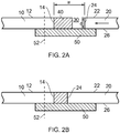
- Figs. 2A and 2B illustrate the assembly of Figs. 1A and 1B in use.
- the gap seal 40 partially extends across the width, w, of the gap 30, and extends across its full depth, d.
- the gap seal 40 is not compressed in the closing configuration.
- the width, w, of the gap 30 reduces so that the internal surface 26 of the second panel 20 slides across the blade seal 50, and the gap seal 40 is compressed in the first direction (the width direction).
- the width of the gap seal 40 reduces.
- the depth of the gap seal 40 does not increase, and the gap seal 40 retains a depth that corresponds to the depth, d, of the gap 30.
- the elastomers typically used for gap seals in the prior art have a very high poisson's ratio in the region of 0.4999, and would therefore be expected to expand in the depth direction by an amount corresponding to the compression in the width direction.
- the material used for the gap seal 40 of the present invention is engineered to deliver a near-zero poisson's ratio.
- a poisson's ratio of equal to or less than 0.1 is acceptable, but it is preferably equal to or less than 0.05 +/- 20%.
- Fig. 3 shows a detail view of a macro-structure of a material 60 suitable for forming the gap seal 40.
- the material comprises a substrate 62 formed with a grid of identical cells 64.
- Each cell 64 has a generally hexagonal shape, with a slot-shaped aperture 66 at each of its six edges.
- Each aperture is orientated so that its longitudinal axis is at an angle ⁇ to the normal of its respective notional edge of the hexagon. This angle ⁇ is uniform for each of the six apertures, so that the cell 64 has six-fold rotational symmetry.
- the cells 64 are arranged in the grid such that each cell 64 has a different neighbour at each of its six sides, and neighbouring cells 64 share a common aperture at the interface between them.
- the grid thus resembles a honeycomb structure.
- Materials suitable for providing the substrate 62 of the material 60 include elastomers, polyurethane, polytetrafluoroethylene (PTFE), silicon rubber, neoprene and cork. Suitable materials must be able to meet airworthiness requirements to ensure durability in the harsh environmental conditions experienced by aircraft.
- the material 60 may be formed by additive manufacturing methods (3D printing) or any other suitable method.
- the cell 64 may have a different number of sides, such as three or more sides, and/or the apertures 66 may have a different shape or orientation.
- the material may comprise an isotropic lattice comprising interconnected cells each formed from arm members forming a two-dimensional or three-dimensional truss.
- Figs. 4A-D illustrate an embodiment of the present invention integrated into a folding wing assembly.
- Features of this embodiment relating to the gap seal and blade seal are identical to those described above in relation to Figs 1 to 3 .
- Figs. 4A and B show the wing in a folded (open) configuration
- Figs. 4C and 4D show the wing in a flight (closed) configuration.
- the folding wing assembly includes an inner wing section 100 and an outer wing section 200 which pivots relative to the inner wing section 100 between the open and closed configurations.
- the gap seal 140 In the folded configuration ( Figs. 4A and B ) the gap seal 140 partially extends across the width, w, of the gap 130, and extends across its full depth, d. Thus, the gap seal 140 is not compressed in the folded configuration.
- the first and second panels 110, 120 move towards one another until the assembly is in the flight configuration shown in Figs. 4C and D .
- the width, w, of the gap 130 reduces so that the internal surface 126 of the second panel 120 slides across the blade seal 150, and the gap seal 140 is compressed in the first direction (the width direction).
- the width of the gap seal 140 reduces.
- the depth of the gap seal 140 does not increase, and the gap seal 140 retains a depth that corresponds to the depth, d, of the gap 130.
- this is achieved by engineering the material used for the gap seal 140 so that it has a near-zero poisson's ratio.
- a poisson's ratio of equal to or less than 0.1 is acceptable, but it is preferably equal to or less than 0.05 +/-20%.
- the materials and material configurations described in relation to the previous embodiments are suitable for use in the present embodiment.
Landscapes
- Engineering & Computer Science (AREA)
- Mechanical Engineering (AREA)
- Aviation & Aerospace Engineering (AREA)
- General Engineering & Computer Science (AREA)
- Physics & Mathematics (AREA)
- Fluid Mechanics (AREA)
- Gasket Seals (AREA)
- Sealing Devices (AREA)
Applications Claiming Priority (1)
| Application Number | Priority Date | Filing Date | Title |
|---|---|---|---|
| GB1619292.4A GB2555861A (en) | 2016-11-15 | 2016-11-15 | Aircraft gap seal |
Publications (1)
| Publication Number | Publication Date |
|---|---|
| EP3321175A1 true EP3321175A1 (de) | 2018-05-16 |
Family
ID=60301894
Family Applications (1)
| Application Number | Title | Priority Date | Filing Date |
|---|---|---|---|
| EP17201055.5A Withdrawn EP3321175A1 (de) | 2016-11-15 | 2017-11-10 | Flugzeugspaltdichtung |
Country Status (4)
| Country | Link |
|---|---|
| US (1) | US10871232B2 (de) |
| EP (1) | EP3321175A1 (de) |
| CN (1) | CN108069017A (de) |
| GB (1) | GB2555861A (de) |
Cited By (2)
| Publication number | Priority date | Publication date | Assignee | Title |
|---|---|---|---|---|
| CN109400994A (zh) * | 2018-10-31 | 2019-03-01 | 江苏伊顿航天材料股份有限公司 | 一种航天密封器件用改性橡胶复合材料及其制备方法 |
| WO2020049296A1 (en) * | 2018-09-05 | 2020-03-12 | Edwards Limited | Non-elastomer seals, vacuum pump systems with such seals and a method of manufacture of such seals |
Families Citing this family (9)
| Publication number | Priority date | Publication date | Assignee | Title |
|---|---|---|---|---|
| GB2569939B (en) * | 2017-10-19 | 2021-02-10 | Airbus Operations Ltd | Aerodynamic seals |
| FR3081831A1 (fr) * | 2018-05-30 | 2019-12-06 | Airbus Operations | Paroi aerodynamique d’aeronef comportant au moins un generateur de tourbillons et aeronef comprenant ladite paroi aerodynamique |
| US11192632B2 (en) * | 2018-10-15 | 2021-12-07 | The Boeing Company | Slat end seal and method for manufacturing the same |
| CN110877712A (zh) * | 2019-12-02 | 2020-03-13 | 北京电子工程总体研究所 | 一种折叠舵面的折叠间隙调节装置 |
| GB2601768A (en) * | 2020-12-09 | 2022-06-15 | Airbus Operations Ltd | Aircraft hinge assembly |
| CN114802698B (zh) | 2021-01-27 | 2026-02-24 | 波音公司 | 在飞机中用于连接中央翼盒和隔舱的接头 |
| EP4035993A1 (de) * | 2021-01-27 | 2022-08-03 | The Boeing Company | Verbinder zum verbinden eines mittelflügelkastens mit einem schott eines flugzeuges |
| US11945568B2 (en) * | 2021-03-01 | 2024-04-02 | The Boeing Company | Hybrid pressure deck for aircraft |
| CN113431900B (zh) * | 2021-05-25 | 2022-09-27 | 宣城格林达橡塑密封科技有限公司 | 一种橡胶密封胶条 |
Citations (5)
| Publication number | Priority date | Publication date | Assignee | Title |
|---|---|---|---|---|
| US6009669A (en) * | 1999-03-11 | 2000-01-04 | Northrop Grumman Corporation | Shape memory wire actuated aircraft door seal |
| EP1661805A1 (de) * | 2004-11-24 | 2006-05-31 | Airbus Deutschland GmbH | Deckhaut für eine formvariable aerodynamische Fläche |
| US20080035788A1 (en) * | 2006-08-11 | 2008-02-14 | Techno-Sciences, Inc. | Cellular support structures used for controlled actuation of fluid contact surfaces |
| US20090267304A1 (en) * | 2008-04-23 | 2009-10-29 | Airbus Uk Limited | Flight surface seal |
| EP2587038A1 (de) * | 2011-10-24 | 2013-05-01 | United Technologies Corporation | Dichtung mit variabler Spaltbreite |
Family Cites Families (8)
| Publication number | Priority date | Publication date | Assignee | Title |
|---|---|---|---|---|
| GB0800770D0 (en) * | 2008-01-17 | 2008-02-27 | Airbus Uk Ltd | Aerofynamic sealing member for aircraft |
| GB0908354D0 (en) * | 2009-05-15 | 2009-06-24 | Airbus Uk Ltd | Blade seal |
| US20110059291A1 (en) * | 2009-09-07 | 2011-03-10 | Boyce Christopher M | Structured materials with tailored isotropic and anisotropic poisson's ratios including negative and zero poisson's ratios |
| GB201008863D0 (en) * | 2010-05-27 | 2010-07-14 | Airbus Operations Ltd | Method of sealing a gap |
| GB2514074A (en) * | 2011-09-06 | 2014-11-19 | Univ Malta | Stents with zero poisson's ratio cells |
| DE102011120762A1 (de) * | 2011-12-09 | 2013-06-13 | Airbus Operations Gmbh | Abdeckungsvorrichtung sowie Flugzeugbereich mit Abdeckungsvorrichtung |
| CN104763772B (zh) * | 2015-03-31 | 2017-03-08 | 华南理工大学 | 一种缓冲吸能结构 |
| US10017239B2 (en) * | 2015-12-18 | 2018-07-10 | Northrop Grumman Systems Corporation | Dynamic conformal aerodynamic seal (CAS) for aircraft control surfaces |
-
2016
- 2016-11-15 GB GB1619292.4A patent/GB2555861A/en not_active Withdrawn
-
2017
- 2017-11-10 EP EP17201055.5A patent/EP3321175A1/de not_active Withdrawn
- 2017-11-15 CN CN201711128843.XA patent/CN108069017A/zh active Pending
- 2017-11-15 US US15/813,516 patent/US10871232B2/en active Active
Patent Citations (5)
| Publication number | Priority date | Publication date | Assignee | Title |
|---|---|---|---|---|
| US6009669A (en) * | 1999-03-11 | 2000-01-04 | Northrop Grumman Corporation | Shape memory wire actuated aircraft door seal |
| EP1661805A1 (de) * | 2004-11-24 | 2006-05-31 | Airbus Deutschland GmbH | Deckhaut für eine formvariable aerodynamische Fläche |
| US20080035788A1 (en) * | 2006-08-11 | 2008-02-14 | Techno-Sciences, Inc. | Cellular support structures used for controlled actuation of fluid contact surfaces |
| US20090267304A1 (en) * | 2008-04-23 | 2009-10-29 | Airbus Uk Limited | Flight surface seal |
| EP2587038A1 (de) * | 2011-10-24 | 2013-05-01 | United Technologies Corporation | Dichtung mit variabler Spaltbreite |
Cited By (3)
| Publication number | Priority date | Publication date | Assignee | Title |
|---|---|---|---|---|
| WO2020049296A1 (en) * | 2018-09-05 | 2020-03-12 | Edwards Limited | Non-elastomer seals, vacuum pump systems with such seals and a method of manufacture of such seals |
| KR20210001048U (ko) * | 2018-09-05 | 2021-05-13 | 에드워즈 리미티드 | 비-엘라스토머 시일, 이러한 시일을 갖는 진공 펌프 시스템 및 이러한 시일의 제조 방법 |
| CN109400994A (zh) * | 2018-10-31 | 2019-03-01 | 江苏伊顿航天材料股份有限公司 | 一种航天密封器件用改性橡胶复合材料及其制备方法 |
Also Published As
| Publication number | Publication date |
|---|---|
| US20180135760A1 (en) | 2018-05-17 |
| GB2555861A (en) | 2018-05-16 |
| US10871232B2 (en) | 2020-12-22 |
| CN108069017A (zh) | 2018-05-25 |
Similar Documents
| Publication | Publication Date | Title |
|---|---|---|
| US10871232B2 (en) | Aircraft gap seal | |
| US7896294B2 (en) | Cover skin for a variable-shape aerodynamic area | |
| US10654557B2 (en) | Morphing skin for an aircraft | |
| US9452819B2 (en) | Flight control surface seal | |
| EP2334548B1 (de) | Dichtung zum abdichten eines spalts zwischen einer ersten und einer zweiten komponente einer flugzeugsteuerfläche | |
| US9873503B2 (en) | Tailplane with positive camber | |
| US11346446B2 (en) | Seal | |
| US8876051B2 (en) | Bridging seal | |
| US9862480B2 (en) | Aerodynamic device | |
| KR102409780B1 (ko) | 날개 플랩 편향 제어 제거 | |
| JP7191673B2 (ja) | 空気力学的表面用シールプレート | |
| US2329133A (en) | Aircraft construction | |
| RU2625478C2 (ru) | Эластомерная управляющая поверхность на основе технологии получения непрерывного обвода | |
| US12054257B2 (en) | Flexible pillar for a flexible frame of a variable geometry flight control surface | |
| US9180961B2 (en) | Control surface for creating variable camber along a wing | |
| US10150557B2 (en) | Shape-variable gap covering between control surfaces and adjacent structural components on aircrafts | |
| US10640196B1 (en) | Aircraft blade seal |
Legal Events
| Date | Code | Title | Description |
|---|---|---|---|
| PUAI | Public reference made under article 153(3) epc to a published international application that has entered the european phase |
Free format text: ORIGINAL CODE: 0009012 |
|
| AK | Designated contracting states |
Kind code of ref document: A1 Designated state(s): AL AT BE BG CH CY CZ DE DK EE ES FI FR GB GR HR HU IE IS IT LI LT LU LV MC MK MT NL NO PL PT RO RS SE SI SK SM TR |
|
| AX | Request for extension of the european patent |
Extension state: BA ME |
|
| STAA | Information on the status of an ep patent application or granted ep patent |
Free format text: STATUS: THE APPLICATION IS DEEMED TO BE WITHDRAWN |
|
| 18D | Application deemed to be withdrawn |
Effective date: 20181117 |