EP3321494A1 - Getriebe für gasturbinenmotoren - Google Patents
Getriebe für gasturbinenmotoren Download PDFInfo
- Publication number
- EP3321494A1 EP3321494A1 EP17194136.2A EP17194136A EP3321494A1 EP 3321494 A1 EP3321494 A1 EP 3321494A1 EP 17194136 A EP17194136 A EP 17194136A EP 3321494 A1 EP3321494 A1 EP 3321494A1
- Authority
- EP
- European Patent Office
- Prior art keywords
- gear
- planet gears
- gearbox
- carrier
- gas turbine
- Prior art date
- Legal status (The legal status is an assumption and is not a legal conclusion. Google has not performed a legal analysis and makes no representation as to the accuracy of the status listed.)
- Granted
Links
Images






Classifications
-
- F—MECHANICAL ENGINEERING; LIGHTING; HEATING; WEAPONS; BLASTING
- F02—COMBUSTION ENGINES; HOT-GAS OR COMBUSTION-PRODUCT ENGINE PLANTS
- F02C—GAS-TURBINE PLANTS; AIR INTAKES FOR JET-PROPULSION PLANTS; CONTROLLING FUEL SUPPLY IN AIR-BREATHING JET-PROPULSION PLANTS
- F02C3/00—Gas-turbine plants characterised by the use of combustion products as the working fluid
- F02C3/04—Gas-turbine plants characterised by the use of combustion products as the working fluid having a turbine driving a compressor
- F02C3/107—Gas-turbine plants characterised by the use of combustion products as the working fluid having a turbine driving a compressor with two or more rotors connected by power transmission
- F02C3/113—Gas-turbine plants characterised by the use of combustion products as the working fluid having a turbine driving a compressor with two or more rotors connected by power transmission with variable power transmission between rotors
-
- F—MECHANICAL ENGINEERING; LIGHTING; HEATING; WEAPONS; BLASTING
- F02—COMBUSTION ENGINES; HOT-GAS OR COMBUSTION-PRODUCT ENGINE PLANTS
- F02K—JET-PROPULSION PLANTS
- F02K3/00—Plants including a gas turbine driving a compressor or a ducted fan
- F02K3/02—Plants including a gas turbine driving a compressor or a ducted fan in which part of the working fluid by-passes the turbine and combustion chamber
- F02K3/04—Plants including a gas turbine driving a compressor or a ducted fan in which part of the working fluid by-passes the turbine and combustion chamber the plant including ducted fans, i.e. fans with high volume, low pressure outputs, for augmenting the jet thrust, e.g. of double-flow type
- F02K3/06—Plants including a gas turbine driving a compressor or a ducted fan in which part of the working fluid by-passes the turbine and combustion chamber the plant including ducted fans, i.e. fans with high volume, low pressure outputs, for augmenting the jet thrust, e.g. of double-flow type with front fan
-
- F—MECHANICAL ENGINEERING; LIGHTING; HEATING; WEAPONS; BLASTING
- F02—COMBUSTION ENGINES; HOT-GAS OR COMBUSTION-PRODUCT ENGINE PLANTS
- F02C—GAS-TURBINE PLANTS; AIR INTAKES FOR JET-PROPULSION PLANTS; CONTROLLING FUEL SUPPLY IN AIR-BREATHING JET-PROPULSION PLANTS
- F02C6/00—Plural gas-turbine plants; Combinations of gas-turbine plants with other apparatus; Adaptations of gas-turbine plants for special use
- F02C6/20—Adaptations of gas-turbine plants for driving vehicles
- F02C6/206—Adaptations of gas-turbine plants for driving vehicles the vehicles being airscrew driven
-
- F—MECHANICAL ENGINEERING; LIGHTING; HEATING; WEAPONS; BLASTING
- F02—COMBUSTION ENGINES; HOT-GAS OR COMBUSTION-PRODUCT ENGINE PLANTS
- F02C—GAS-TURBINE PLANTS; AIR INTAKES FOR JET-PROPULSION PLANTS; CONTROLLING FUEL SUPPLY IN AIR-BREATHING JET-PROPULSION PLANTS
- F02C7/00—Features, components parts, details or accessories, not provided for in, or of interest apart form groups F02C1/00 - F02C6/00; Air intakes for jet-propulsion plants
- F02C7/36—Power transmission arrangements between the different shafts of the gas turbine plant, or between the gas-turbine plant and the power user
-
- F—MECHANICAL ENGINEERING; LIGHTING; HEATING; WEAPONS; BLASTING
- F16—ENGINEERING ELEMENTS AND UNITS; GENERAL MEASURES FOR PRODUCING AND MAINTAINING EFFECTIVE FUNCTIONING OF MACHINES OR INSTALLATIONS; THERMAL INSULATION IN GENERAL
- F16H—GEARING
- F16H3/00—Toothed gearings for conveying rotary motion with variable gear ratio or for reversing rotary motion
- F16H3/44—Toothed gearings for conveying rotary motion with variable gear ratio or for reversing rotary motion using gears having orbital motion
- F16H3/46—Gearings having only two central gears, connected by orbital gears
- F16H3/48—Gearings having only two central gears, connected by orbital gears with single orbital gears or pairs of rigidly-connected orbital gears
- F16H3/52—Gearings having only two central gears, connected by orbital gears with single orbital gears or pairs of rigidly-connected orbital gears comprising orbital spur gears
- F16H3/54—Gearings having only two central gears, connected by orbital gears with single orbital gears or pairs of rigidly-connected orbital gears comprising orbital spur gears one of the central gears being internally toothed and the other externally toothed
-
- F—MECHANICAL ENGINEERING; LIGHTING; HEATING; WEAPONS; BLASTING
- F16—ENGINEERING ELEMENTS AND UNITS; GENERAL MEASURES FOR PRODUCING AND MAINTAINING EFFECTIVE FUNCTIONING OF MACHINES OR INSTALLATIONS; THERMAL INSULATION IN GENERAL
- F16H—GEARING
- F16H3/00—Toothed gearings for conveying rotary motion with variable gear ratio or for reversing rotary motion
- F16H3/44—Toothed gearings for conveying rotary motion with variable gear ratio or for reversing rotary motion using gears having orbital motion
- F16H3/46—Gearings having only two central gears, connected by orbital gears
- F16H3/58—Gearings having only two central gears, connected by orbital gears with sets of orbital gears, each consisting of two or more intermeshing orbital gears
-
- F—MECHANICAL ENGINEERING; LIGHTING; HEATING; WEAPONS; BLASTING
- F16—ENGINEERING ELEMENTS AND UNITS; GENERAL MEASURES FOR PRODUCING AND MAINTAINING EFFECTIVE FUNCTIONING OF MACHINES OR INSTALLATIONS; THERMAL INSULATION IN GENERAL
- F16H—GEARING
- F16H3/00—Toothed gearings for conveying rotary motion with variable gear ratio or for reversing rotary motion
- F16H3/44—Toothed gearings for conveying rotary motion with variable gear ratio or for reversing rotary motion using gears having orbital motion
- F16H3/62—Gearings having three or more central gears
- F16H3/66—Gearings having three or more central gears composed of a number of gear trains without drive passing from one train to another
-
- F—MECHANICAL ENGINEERING; LIGHTING; HEATING; WEAPONS; BLASTING
- F16—ENGINEERING ELEMENTS AND UNITS; GENERAL MEASURES FOR PRODUCING AND MAINTAINING EFFECTIVE FUNCTIONING OF MACHINES OR INSTALLATIONS; THERMAL INSULATION IN GENERAL
- F16H—GEARING
- F16H3/00—Toothed gearings for conveying rotary motion with variable gear ratio or for reversing rotary motion
- F16H3/44—Toothed gearings for conveying rotary motion with variable gear ratio or for reversing rotary motion using gears having orbital motion
- F16H3/62—Gearings having three or more central gears
- F16H3/66—Gearings having three or more central gears composed of a number of gear trains without drive passing from one train to another
- F16H3/666—Gearings having three or more central gears composed of a number of gear trains without drive passing from one train to another with intermeshing orbital gears
-
- F—MECHANICAL ENGINEERING; LIGHTING; HEATING; WEAPONS; BLASTING
- F05—INDEXING SCHEMES RELATING TO ENGINES OR PUMPS IN VARIOUS SUBCLASSES OF CLASSES F01-F04
- F05D—INDEXING SCHEME FOR ASPECTS RELATING TO NON-POSITIVE-DISPLACEMENT MACHINES OR ENGINES, GAS-TURBINES OR JET-PROPULSION PLANTS
- F05D2260/00—Function
- F05D2260/40—Transmission of power
- F05D2260/403—Transmission of power through the shape of the drive components
- F05D2260/4031—Transmission of power through the shape of the drive components as in toothed gearing
- F05D2260/40311—Transmission of power through the shape of the drive components as in toothed gearing of the epicyclical, planetary or differential type
-
- F—MECHANICAL ENGINEERING; LIGHTING; HEATING; WEAPONS; BLASTING
- F16—ENGINEERING ELEMENTS AND UNITS; GENERAL MEASURES FOR PRODUCING AND MAINTAINING EFFECTIVE FUNCTIONING OF MACHINES OR INSTALLATIONS; THERMAL INSULATION IN GENERAL
- F16H—GEARING
- F16H2200/00—Transmissions for multiple ratios
- F16H2200/003—Transmissions for multiple ratios characterised by the number of forward speeds
- F16H2200/0034—Transmissions for multiple ratios characterised by the number of forward speeds the gear ratios comprising two forward speeds
-
- F—MECHANICAL ENGINEERING; LIGHTING; HEATING; WEAPONS; BLASTING
- F16—ENGINEERING ELEMENTS AND UNITS; GENERAL MEASURES FOR PRODUCING AND MAINTAINING EFFECTIVE FUNCTIONING OF MACHINES OR INSTALLATIONS; THERMAL INSULATION IN GENERAL
- F16H—GEARING
- F16H2200/00—Transmissions for multiple ratios
- F16H2200/20—Transmissions using gears with orbital motion
- F16H2200/2002—Transmissions using gears with orbital motion characterised by the number of sets of orbital gears
- F16H2200/2005—Transmissions using gears with orbital motion characterised by the number of sets of orbital gears with one sets of orbital gears
-
- F—MECHANICAL ENGINEERING; LIGHTING; HEATING; WEAPONS; BLASTING
- F16—ENGINEERING ELEMENTS AND UNITS; GENERAL MEASURES FOR PRODUCING AND MAINTAINING EFFECTIVE FUNCTIONING OF MACHINES OR INSTALLATIONS; THERMAL INSULATION IN GENERAL
- F16H—GEARING
- F16H2200/00—Transmissions for multiple ratios
- F16H2200/20—Transmissions using gears with orbital motion
- F16H2200/203—Transmissions using gears with orbital motion characterised by the engaging friction means not of the freewheel type, e.g. friction clutches or brakes
- F16H2200/2035—Transmissions using gears with orbital motion characterised by the engaging friction means not of the freewheel type, e.g. friction clutches or brakes with two engaging means
Definitions
- the application relates generally to the transmission of power in aircraft engines and, more particularly, to gearboxes through which an aircraft engine shaft can drive a load.
- a gearbox for a gas turbine engine comprising: a gear assembly including first and second gears in driving engagement through planet gears, the planet gears rotatable about a respective central axis and supported by a carrier, the assembly connected to input and output shafts and including at least one rotatable intermediate component; a brake configured to selectively impede rotation of the intermediate component; and a blocking member configured to selectively impede rotation of the planet gears about the central axes; wherein the gearbox is selectively configurable between: a speed change configuration wherein the brake is configured to impede the rotation of the intermediate component and the blocking member is configured to allow the rotation of the planet gears about the central axes to define a speed ratio different than 1 between rotational speeds of the input and output shafts; and a direct drive configuration wherein the brake is configured to allow the rotation of the intermediate component and the blocking member is configured to impede the rotation of the planet gears about the central axes so that the input and output shafts are rotatable together
- a gas turbine engine comprising: an input shaft drivingly engaged to a turbine rotor; an output shaft drivingly engaged to a drivable rotor; and a gearbox including first and second gears in driving engagement through planet gears, the planet gears rotatable about a respective central axis and supported by a carrier, wherein: one of the first gear, second gear and carrier is connected to the input shaft, another one of the first gear, second gear and carrier is connected to the output shaft, and a remaining one of the first gear, second gear and carrier is an intermediate component, the gearbox further including a brake and a blocking member, the brake selectively movable between a brake position impeding rotation of the intermediate component and a release position allowing rotation of the intermediate component, the blocking member selectively movable between an engaged position impeding rotation of the planet gears about the central axes and a disengaged position allowing rotation of the planet gears about the central axes; wherein the gearbox is selectively configurable between: a
- a method of rotating a rotor of a gas turbine engine through a gearbox including first and second gears drivingly interconnected by rotatable planet gears supported by a carrier comprising: rotating an input shaft with a turbine section of the gas turbine engine; rotating one of the first gear, the second gear and the carrier with the input shaft while another one of the first gear, the second gear and the carrier is connected to an output shaft and a remaining one of the first gear, the second gear and the carrier is an intermediate component; configuring the gearbox in a selected one of a direct drive configuration and a speed change configuration, including: when the direct drive configuration is selected, preventing rotation of the planet gears while allowing rotation of the intermediate component so that the input and output shafts rotate together as a single shaft at a same rotational speed, and when the second configuration is selected, preventing rotation of the intermediate component while allowing rotation of the planet gears so that the input and output shafts rotate at different rotational speeds; and driving the output shaft with the input shaft through the gear
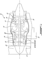
- Fig. 1 illustrates a gas turbine engine 10 of a type preferably provided for use in subsonic flight, generally comprising in serial flow communication a fan 12 through which ambient air is propelled, a compressor section 14 for pressurizing the air, a combustor 16 in which the compressed air is mixed with fuel and ignited for generating an annular stream of hot combustion gases, and a turbine section 18 for extracting energy from the combustion gases.
- the gas turbine engine includes low pressure and high pressure shafts 20, 22 which are rotatable independently from one another.
- the two shafts 20, 22 are coaxial and the low pressure shaft 20 extends within the high pressure shaft 22.
- the high pressure shaft 22 is connected to rotor(s) 24 of a high pressure portion of the turbine section 18, so as to be driven by the high pressure turbine rotor(s) 24.
- the low pressure shaft 20 is connected to rotor(s) 26 of a low pressure portion of the turbine section 18, so as to be driven by the low pressure turbine rotor(s) 26 located downstream of the high pressure turbine rotor(s) 24.
- the high pressure shaft 22 is drivingly engaged to one or more rotor(s) 28 of a high pressure portion of the compressor section 14; in the embodiment shown in solid lines, the high pressure compressor rotors 28 are directly connected to the high pressure shaft 22 so as to rotate at the same rotational speed.
- the low pressure shaft 20 is drivingly engaged to the fan 12, and to one or more rotor(s) 30 of a low pressure portion of the compressor section 14, e.g. boost compressor rotor(s), located upstream of the high pressure compressor rotor(s) 28 and downstream of the fan 12.
- the gas turbine engine includes a gearbox 40, 140, 240, 340 through which one of the shafts 20, 22 of the gas turbine engine 10 is drivingly engaged to a rotatable load, such as a drivable rotor.
- a gearbox 40, 140, 240, 340 has two configurations allowing the shaft to drive the rotatable load either through a direct drive (i.e., speed ratio of 1) or through a drive having a speed ratio different from 1, i.e. providing a speed increase or speed decrease.
- the gearbox 40, 140, 240, 340 provides the driving engagement between the low pressure shaft 20 and the low pressure or boost compressor rotor 30. It is understood that the gearbox 40, 140, 240, 340 may additionally or alternately provide the driving engagement between the low pressure shaft 20 and any other suitable drivable rotor or rotatable element of the gas turbine engine, including, but not limited to, the fan 12. The gearbox 40, 140, 240, 340 may alternately provide the driving engagement between the high pressure shaft 22 and any suitable drivable rotor or rotatable element, including, but not limited to, one or more high pressure compressor rotor(s) 28 (as shown in dotted lines), and accessories 32.
- the engine may include more than two rotatable shafts, and the gearbox 40, 140, 240, 340 may be used for example to provide the driving engagement between an intermediate shaft and a drivable rotor or other rotatable element of the gas turbine engine 10.
- the gearbox 40, 140, 240, 340 provides access to increased power for the gas turbine engine 10 by increasing the rotational speed of the boost compressor rotor 30 in certain conditions, e.g., one engine operation, hot temperature, high altitude operation.
- the gearbox 40, 140, 240, 340 can be switched from a direct drive to a speed increase configuration to provide for an increased rotational speed of the boost compressor rotor 30.
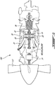
- the gas turbine engine 10 has been shown as a turbofan engine, it is understood that the gas turbine engine 10 may have any other suitable configuration, including, but not limited to, a turboprop and a turboshaft configuration.
- the gearbox 40, 140, 240, 340 may be used in such engines similarly as shown in Fig. 1 .
- switching from a direct drive to a speed increase configuration allows for a propeller speed reduction in certain flight regimes (i.e. rotational speed reduction of the low pressure shaft and accordingly of the input shaft) while maintaining the rotational speed or minimizing the speed reduction of the boost compressor rotor 30.
- the gearbox 40, 140, 240, 340 may be used in the driving engagement between the low pressure/power shaft 20 and the propeller 112, for example in series with a reduction gearbox 34.
- the gearbox 40, 140, 240, 340 can be used to change the propeller speed in certain flight regimes without changing the rotational speed of the driving power turbine rotor(s) 26, for example for noise reduction purposes.
- the input shaft 46 is connected to the driving shaft of the gas turbine engine 10, for example the low pressure shaft 20 ( Fig. 1 ).
- the input shaft 46 may be connected to the driving shaft in any suitable manner, including removable connections (e.g. spline connection, bolted connection) and permanent connections (e.g. integrally formed therewith).
- the output shaft 48 is connected to the drivable rotor or other rotatable load, for example the low pressure or boost compressor rotor 30 ( Fig. 1 ).
- the output shaft 48 may be connected to the drivable rotor or other rotatable load in any suitable manner, including removable connections (e.g. spline connection, bolted connection) and permanent connections (e.g. integrally formed therewith).
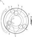
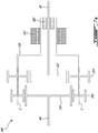
- the gearbox 40 is a planetary gear set, and has a gear assembly including a ring gear 50 and a sun gear 52 in driving engagement with each other through planet gears 54, 56 supported by a rotatable carrier 58.
- the ring gear 50 is the input component and is connected to the input shaft 46
- the sun gear 52 is the output component and is connected to the output shaft 48
- the carrier 58 is an intermediate component.
- Other configurations are possible, as will be further detailed below.
- the particular embodiment of the gearbox 40 shown is selectively configurable between a speed change configuration where the output shaft 48 rotates faster than the input shaft 46, and a direct drive configuration where the input and output shafts 46, 48 rotate together as a single shaft.
- the planet gears include a first set of planet gears 54 in meshed engagement with the sun gear 52 and a second set of planet gears 56 in meshed engagement with the ring gear 50, with corresponding planet gears 54, 56 of the first and second sets being meshed together.
- each set of planet gears 54, 56 is shown as including three planet gears, it is understood that alternately more or less planet gears may be provided.
- the gearbox 40 further includes a blocking member 60 which in an engaged position ( Fig. 2b ) impedes (i.e. prevents) the rotation of the planet gears 54, 56 about their respective central axis C.
- the blocking member 60 is a clutch which in the engaged position connects the carrier 58 (i.e., the intermediate component) to the output shaft 48 so that they are rotatable together at the same rotational speed.
- the clutch 60 connects the carrier 58 and output shaft 48 by engaging a shaft of the carrier 58 and the output shaft 48.
- the clutch 60 can connect the carrier 58 and output shaft 48 by engaging or any other element connected to the carrier 58 and rotatable therewith at the same rotational speed and/or any other element connected to the output shaft 48 and rotatable therewith at the same rotational speed (including, but not limited to, the sun gear 52).
- the clutch 60 prevents the planet gears 54, 56 from rotating about their axes C.
- the clutch 60 also has a disengaged position ( Fig. 2a ) where it is disengaged from one or both of the carrier 58 and the output shaft 48, so they can rotate relative to each other.
- the gearbox also includes a brake 62 which in a brake position ( Fig. 2a ) is engaged the shaft of the carrier 58 (i.e., the intermediate component) to impede (i.e. prevent) its rotation.
- the brake 62 also has a release position ( Fig. 2b ) where it is disengaged from the carrier 58 to allow its rotation.
- clutch is intended to include any mechanism for selectively engaging two rotatable components to each other so that they become rotatable together as a single component at a same rotational speed
- brake is intended to include any mechanism for selectively engaging a rotatable component to impede its rotation. Both terms are intended to include mechanisms that can be engaged automatically and mechanism that require actuation to be engaged.
- the clutch 60 and brake 62 can be similar or identical mechanisms, differing in what they are interconnecting: two rotatable components for the clutch 60, and a rotatable component to a fixed structure for the brake 62.
- the clutch 60 is in its disengaged position, to allow the output shaft 48 and the carrier 58 to rotate with respect to each other.
- the brake 62 is in its brake position, engaged to the shaft of the carrier 58 to impede the rotation of the carrier 58.
- the input shaft 46 rotates the ring gear 50, which drives rotation of the planet gears 54, 56 about their respective axis.
- the axes of the planet gears 54, 56 remain stationary since the carrier 58 is not rotating.
- the rotating planet gears 54, 56 drive rotation of the sun gear 52 and accordingly of the output shaft 48.
- the gearbox 40 defines a speed ratio different than 1 between the rotational speeds of the input and output shafts 46, 48; as mentioned above, in the particular embodiment shown the gearbox 40 provides for a speed increase between the input and output shaft 46, 48.
- the ratio of the rotational speed of the input shaft 46 on the rotational speed of the output shaft 48 ⁇ IN / ⁇ OUT is smaller than 1.
- the brake 62 in its release position, disengaged from the carrier 58 and thus allowing the carrier 58 to rotate.
- the carrier 58 and sun gear 52 both start to rotate about their central axis. Since the sun gear 52 is connected to the load and the carrier 58 is not, the carrier 58, if free, would accelerate faster than the sun gear 52.
- the clutch 60 which in a particular embodiment is a one-way clutch, is in its engaged position and connects the output shaft 48 to the carrier 58 so that they are rotatable together at the same rotational speed.
- the sun gear 52 and carrier 58 are both connected to the output shaft 48 and rotate together at the same rotational speed due to the engaged clutch 60, the planet gears 54, 56 do not rotate about their respective axis.
- the ring gear 50, carrier 58 and sun gear 52 thus all rotate at the same rotational speed, defining a direct drive between the input and output shafts 46, 48 - the input and output shafts 46, 48 rotate together as a single shaft.
- the ratio of the rotational speed of the input shaft 46 on the rotational speed of the output shaft 48 ⁇ IN / ⁇ OUT is 1.
- FIG. 4a , 4b and 5 another particular embodiment of the gearbox 140 is generally shown, where elements similar to that of the gearbox 40 of Figs. 2a , 2b and 3 are designated with the same reference numerals.
- the input shaft 46 is connected to the ring gear 50.
- the output shaft 48 is connected to the carrier 58.
- the sun gear 52 is thus the intermediate component which is selectively engageable by the brake 162, either directly or (as shown here) by having the brake 162 engaging a shaft connected to the sun gear 52.
- the blocking member 60 is a clutch which in the engaged position connects the shaft of the sun gear 58 (i.e., the intermediate component) to the output shaft 48 so that the sun gear 58 and output shaft 48 are rotatable together at the same rotational speed. It is understood that the clutch 60 could alternately engage the sun gear 52 directly or any other component connected to the sun gear 52 and rotatable therewith, and/or any other component connected to the output shaft 48 and rotatable therewith (including, but not limited to, the carrier 58).
- This gearbox 140 is also selectively configurable between a speed change configuration where the output shaft 48 rotates faster than the input shaft 46, and a direct drive configuration where the input and output shafts 46, 48 rotate together as a single shaft.
- the planet gears 154 are each in meshed engagement with both the sun gear 52 and the ring gear 50. Although three planet gears 154 are shown, it is understood that alternately more or less planet gears may be provided.
- the clutch 60 is in its disengaged position, to allow the output shaft 48 and the sun gear 52 to rotate with respect to each other.
- the brake 162 is in its brake position, engaged to the shaft of the sun gear 52 to impede its rotation.
- the input shaft 46 rotates the ring gear 50, which drives rotation of the planet gears 154 about their respective axis.
- the rotating planet gears 154 drive rotation of the carrier 58 and accordingly of the output shaft 48.
- the gearbox 140 defines a speed ratio different than 1 between the rotational speeds of the input and output shafts 46, 48; as mentioned above, in the particular embodiment shown the gearbox 40 provides for a speed increase between the input and output shaft 46, 48, i.e., the ratio of the rotational speed of the input shaft 46 on the rotational speed of the output shaft 48 ⁇ IN / ⁇ OUT is smaller than 1.
- the brake 162 in its release position, disengaged from the shaft of the sun gear 52 and thus allowing for the sun gear 52 to rotate.
- the carrier 58 and sun gear 52 both start to rotate about their central axis. Since the carrier 58 is connected to the load and the sun gear 52 is not, the sun gear 52, if free, would accelerate faster than the carrier 58.
- the clutch 60 is in its engaged position and connects the output shaft 48 to the shaft of the sun gear 52 so that they are rotatable together at the same rotational speed.
- the planet gears 154 do not rotate about their respective axis.
- the ring gear 50, carrier 58 and sun gear 52 thus all rotate at the same rotational speed, defining a direct drive between the input and output shafts 46, 48.
- the input and output shafts 46, 48 rotate together as a single shaft, i.e. the ratio of the rotational speed of the input shaft 46 on the rotational speed of the output shaft 48 ⁇ IN / ⁇ OUT is 1.
- FIG. 6a and 6b another particular embodiment of the gearbox 240 is generally shown, where elements similar to that of the gearboxes 40, 140 are designated with the same reference numerals.
- the output shaft 48 is connected to the carrier 58.
- the input shaft 46 is connected to the sun gear 52.
- the ring gear 50 is thus the intermediate component which is selectively engageable by the brake 262.
- the blocking member 260 includes a second brake engaging the planet gears 154 to directly impede their rotation about their respective axis.
- This gearbox 240 is selectively configurable between a speed change configuration where the output shaft 48 rotates more slowly than the input shaft 46, and a direct drive configuration where the input and output shafts 46, 48 rotate together as a single shaft.
- the planet gears 154 are each in meshed engagement with both the sun gear 52 and the ring gear 50.
- the planet brake 260 is in its disengaged position, to allow the planet gears 154 to rotate about their respective axes.
- the ring gear brake 162 is in its brake position, engaged to the ring gear 50 to impede its rotation.
- the input shaft 46 rotates the sun gear 52, which drives rotation of the planet gears 154 about their respective axis.
- the rotating planet gears 154 drive rotation of the carrier 58 and accordingly of the output shaft 48.
- the gearbox 240 defines a speed ratio different than 1 between the rotational speeds of the input and output shafts 46, 48; as mentioned above, in the particular embodiment shown the gearbox 40 provides for a speed decrease between the input and output shaft 46, 48, i.e. the ratio of the rotational speed of the input shaft 46 on the rotational speed of the output shaft 48 ⁇ IN / ⁇ OUT is greater than 1.
- the ring gear brake 262 in its release position, allowing for the ring gear 50 to rotate.
- the carrier 58 and ring gear 50 both start to rotate about their central axis. Since the carrier 58 is connected to the load and the ring gear 50 is not, the sun gear 50, if free, would accelerate faster than the carrier 58.
- the planet brake 260 is in its engaged position blocks rotation of the planet gears 154 about their respective axes, thus forcing the carrier 58 and ring gear 50 to rotate together at the same rotational speed.
- the ring gear 50, carrier 58 and sun gear 52 thus all rotate at the same rotational speed, defining a direct drive between the input and output shafts 46, 48.
- the input and output shafts 46, 48 rotate together as a single shaft, i.e. the ratio of the rotational speed of the input shaft 46 on the rotational speed of the output shaft 48 ⁇ IN / ⁇ OUT is 1.
- the blocking member e.g., clutch 60, brake 260
- blocking member configured as a brake engageable to the planet gears for configurations 1-2 and as a clutch to connect the intermediate and output components for configurations 3-6.
- a single set of planet gears as shown in Figs. 5 or dual sets of planet gears as shown in Fig. 3 may be used with any of the configurations to obtain the desired relative direction of rotation of the input and output shafts 46, 48.
- the input and output shafts 46, 48 are coaxial, and the gearbox 40 is configured to be used coaxially with the centerline of the gas turbine engine 10. Other configurations are also possible.
- the gearbox 340 includes first and second sun gears 350, 352 in driving engagement with each other through planet gears 354, 356 supported by a rotatable carrier 358.
- the first sun gear 350 is the input component and is connected to the input shaft 46
- the second sun gear 352 is the output component and is connected to the output shaft 48
- the carrier 358 is an intermediate component.
- Other configurations are possible, as will be further detailed below.
- the planet gears include pairs of interconnected planet gears 354, 356 rotatable together about a common axis.
- the pairs of interconnected planet gears 354, 356 each include a smaller planet gear 356 meshed with the input sun gear 350 and a larger planet gear 354 meshed with the output sun gear 352, and the input sun gear 150 is larger than the output sun gear 152.
- This configuration allows for the speed change configuration to define a speed increase between the input and output shaft 46, 48; it is understood that the proportions of the gears 350, 352, 354, 356 can be changed to have an embodiment where the speed change configuration allows for the output shaft 48 to rotate slower than the input shaft 46.
- three pairs of planet gears 534, 356 are shown, it is understood that alternately more or less pairs of planet gears may be provided.
- the gearbox 340 further includes a blocking member 360 which in an engaged position ( Fig. 7b ) impedes the rotation of the planet gears 354, 356 about their respective central axis C.
- the blocking member 360 is a clutch which in the engaged position connects the carrier 358 (i.e., the intermediate component) to the output shaft 48 so that they are rotatable together at the same rotational speed.
- the clutch 360 connects the carrier 358 and the output shaft 48 by engaging a shaft of the carrier 358 and the output shaft 48.
- the clutch 360 can engage any other element connected to the carrier 358 and rotatable therewith at the same rotational speed and/or any other element connected to the output shaft 48 and rotatable therewith at the same rotational speed (including, but not limited to, the output sun gear 352).
- the clutch 360 prevents the planet gears 354, 356 from rotating about their axes C.
- the clutch 360 also has a disengaged position ( Fig. 7a ) where it is disengaged from one or both of the carrier 358 and the output shaft 48, so they can rotate relative to each other.
- the gearbox also includes a brake 362 which in a brake position ( Fig. 7a ) is engaged the shaft of the carrier 358 (i.e., the intermediate component) to impede its rotation.
- the brake 362 also has a release position ( Fig. 7b ) where it is disengaged from the carrier 358 to allow its rotation.
- the clutch 360 is in its disengaged position, to allow the output shaft 48 and the carrier 358 to rotate with respect to each other.
- the brake 362 is in its brake position, engaged to the shaft of the carrier 358 to impede the rotation of the carrier 358.
- the input shaft 46 rotates the input sun gear 350, which drives rotation of the planet gears 354, 356 about their respective axis.
- the axes of the planet gears 354, 356 remain stationary since the carrier 358 is not rotating.
- the rotating planet gears 354, 356 drive rotation of the output sun gear 352 and accordingly of the output shaft 48.
- the ratio of the rotational speed of the input shaft 46 on the rotational speed of the output shaft 48 ⁇ IN / ⁇ OUT is different from 1.
- the brake 362 in its release position, disengaged from the carrier 358 and thus allowing for the carrier 358 to rotate.
- the carrier 358 and output sun gear 352 both start to rotate about their central axis. Since the output sun gear 352 is connected to the load and the carrier 358 is not, the carrier 358, if free, would accelerate faster than the output sun gear 352.
- the clutch 360 is in its engaged position and connects the output shaft 48 to the carrier 358 so that they are rotatable together at the same rotational speed.
- the planet gears 354, 356 do not rotate about their respective axis.
- the ring gear 350, carrier 358 and sun gear 352 thus all rotate at the same rotational speed, defining a direct drive between the input and output shafts 46, 48 - the input and output shafts 46, 48 rotate together as a single shaft, with the ratio of the rotational speed of the input shaft 46 on the rotational speed of the output shaft 48 ⁇ IN / ⁇ OUT being 1.
- various configurations may be obtained by having one of the sun gears 350, 352 and carrier 358 as the input component connected to the input shaft 46, another one of the sun gears 350, 352 and carrier 358 as the output component connected to the output shaft 48, and the remaining one of the sun gears 350, 352 and carrier 358 as the intermediate component which is engaged by the brake 362 in the speed change configuration.
- the blocking member e.g., clutch 360
- each planet gear may be replaced by two meshed planet gears each meshed with a respective one of the sun/ring gears, similarly to the embodiment shown in Fig. 3 .
- failure, malfunction or wear of the brakes 62, 162, 262, 362 can be detected by the control system of the engine 10 (electronic engine controller or EEC) through detection of the resulting increased rotational speed of the output shaft 48.
- Malfunction or wear of the blocking member e.g. clutch 60, 360, brake 260
- the EEC can be detected by the EEC through detection of the resulting inconsistencies between the rotational speed of the input shaft 46 and the rotational speeds of the output shaft 48.
- a rotor (e.g. boost compressor rotor 30, propeller 112) of the gas turbine engine 10 is thus rotated in accordance with the following.
- the input shaft 46 is rotated with a turbine section 18 of the gas turbine engine 10, for example through a direct connection between one or more rotor(s) of the turbine section 18 and a gas turbine shaft (e.g. low pressure turbine rotor(s) 26 and shaft 20) and a direct connection between the gas turbine shaft and the input shaft.
- a gas turbine shaft e.g. low pressure turbine rotor(s) 26 and shaft 20
- One component between the sun/ring gears 50, 52, 350, 352 and the carrier 58, 358 is rotated with the input shaft 46 while another one of the sun/ring gears 50, 52, 350, 352 and the carrier 58, 358 is connected to the output shaft 48 and the remaining one of the sun/ring gears 50, 52, 350, 352 and the carrier 58, 358 defines the intermediate component.
- the rotation of the planet gears 54, 56, 154, 354, 356 is impeded while allowing rotation of the intermediate component so that the input and output shafts 48 rotate together as a single shaft at a same rotational speed.
- the rotation of the intermediate component is impeded while allowing rotation of the planet gears 54, 56, 154, 354, 356 so that the input and output shafts 46, 48 rotate with different rotational speeds.
- the output shaft 48 is then driven by the input shaft 46 through the gearbox 40, 140, 240, 340 in the selected configuration, and the rotor is rotated with the output shaft 48.
- gearbox 40, 140, 240, 340 has been described as part of a gas turbine engine 10, it is understood that the gearbox 40, 140, 240, 340 may alternately be used in other suitable applications where an alternate direct drive/speed change drive is beneficial.
Landscapes
- Engineering & Computer Science (AREA)
- General Engineering & Computer Science (AREA)
- Mechanical Engineering (AREA)
- Chemical & Material Sciences (AREA)
- Combustion & Propulsion (AREA)
- Structure Of Transmissions (AREA)
Applications Claiming Priority (1)
| Application Number | Priority Date | Filing Date | Title |
|---|---|---|---|
| US15/351,611 US10113482B2 (en) | 2016-11-15 | 2016-11-15 | Gearbox for gas turbine engine |
Publications (2)
| Publication Number | Publication Date |
|---|---|
| EP3321494A1 true EP3321494A1 (de) | 2018-05-16 |
| EP3321494B1 EP3321494B1 (de) | 2024-10-30 |
Family
ID=60001736
Family Applications (1)
| Application Number | Title | Priority Date | Filing Date |
|---|---|---|---|
| EP17194136.2A Active EP3321494B1 (de) | 2016-11-15 | 2017-09-29 | Getriebe für gasturbinenmotoren |
Country Status (3)
| Country | Link |
|---|---|
| US (2) | US10113482B2 (de) |
| EP (1) | EP3321494B1 (de) |
| CA (1) | CA2978702A1 (de) |
Cited By (3)
| Publication number | Priority date | Publication date | Assignee | Title |
|---|---|---|---|---|
| EP3617550A1 (de) * | 2018-08-29 | 2020-03-04 | Pratt & Whitney Canada Corp. | Getriebe für einen motor mit zwei leistungseingängen |
| CN111102310A (zh) * | 2018-10-29 | 2020-05-05 | 普拉特 - 惠特尼加拿大公司 | 具有离合器和机械锁的飞行器发动机 |
| JPWO2020105085A1 (ja) * | 2018-11-19 | 2021-11-11 | 川崎重工業株式会社 | 航空機用の発電装置 |
Families Citing this family (22)
| Publication number | Priority date | Publication date | Assignee | Title |
|---|---|---|---|---|
| US10563577B2 (en) * | 2016-08-22 | 2020-02-18 | United Technologies Corporation | Low rotor boost compressor for engine cooling circuit |
| US10465611B2 (en) | 2016-09-15 | 2019-11-05 | Pratt & Whitney Canada Corp. | Reverse flow multi-spool gas turbine engine with aft-end accessory gearbox drivingly connected to both high pressure spool and low pressure spool |
| US10767568B2 (en) * | 2018-09-11 | 2020-09-08 | Raytheon Technologies Corporation | Dual spool power extraction with superposition gearbox |
| US10890115B2 (en) * | 2018-09-28 | 2021-01-12 | Raytheon Technologies Corporation | Low torque engine starting with dual spool power extraction with superposition gearbox |
| US11041444B2 (en) * | 2018-11-02 | 2021-06-22 | Pratt & Whitney Canada Corp. | Gas turbine engine with differential gearbox |
| US11028905B2 (en) | 2019-03-14 | 2021-06-08 | Hamilton Sundstrand Corporation | Coupled planetary gearbox |
| US11174916B2 (en) | 2019-03-21 | 2021-11-16 | Pratt & Whitney Canada Corp. | Aircraft engine reduction gearbox |
| US11485503B2 (en) * | 2019-03-29 | 2022-11-01 | Pratt & Whitney Canada Corp. | Hybrid aircraft propulsion power plants |
| US11274729B2 (en) * | 2019-07-18 | 2022-03-15 | Rolls-Royce Plc | Turbofan gas turbine engine with gearbox |
| US11313438B2 (en) * | 2019-07-18 | 2022-04-26 | Rolls-Royce Plc | Turbofan gas turbine engine with gearbox |
| US11268453B1 (en) | 2021-03-17 | 2022-03-08 | Pratt & Whitney Canada Corp. | Lubrication system for aircraft engine reduction gearbox |
| EP4283162A1 (de) * | 2022-05-26 | 2023-11-29 | RTX Corporation | Selektive leistungsverteilung für ein flugzeugantriebssystem |
| US12378000B2 (en) | 2022-08-12 | 2025-08-05 | Rtx Corporation | Aircraft propulsion system geartrain |
| US12292005B2 (en) * | 2022-08-12 | 2025-05-06 | Rtx Corporation | Aircraft propulsion system geartrain |
| EP4365429A1 (de) * | 2022-11-04 | 2024-05-08 | RTX Corporation | Getriebe für ein flugzeugantriebssystem |
| US12584446B2 (en) * | 2023-06-21 | 2026-03-24 | General Electric Company | Unidirectional fan brake for a gas turbine engine |
| US12188551B1 (en) | 2023-09-29 | 2025-01-07 | Rtx Corporation | Reduced clearance interface between a fluid device and a rotating structure for a geartrain |
| US12331683B2 (en) | 2023-09-29 | 2025-06-17 | Rtx Corporation | Bearing arrangement for turbine engine geartrain |
| US12135076B1 (en) | 2023-09-29 | 2024-11-05 | Rtx Corporation | Fluid device(s) for supporting rotating structure(s) of a turbine engine |
| US20250109712A1 (en) * | 2023-09-29 | 2025-04-03 | Rtx Corporation | Selective power distribution for an aircraft propulsion system |
| US12292107B2 (en) * | 2023-09-29 | 2025-05-06 | Rtx Corporation | Fluid damper for turbine engine geartrain assembly |
| US12460577B2 (en) * | 2024-03-27 | 2025-11-04 | Rtx Corporation | AFT gear based engine with heat recovery system |
Citations (5)
| Publication number | Priority date | Publication date | Assignee | Title |
|---|---|---|---|---|
| US4862009A (en) * | 1988-03-22 | 1989-08-29 | General Electric Company | Combined electric starter and alternator system using a permanent magnet synchronous machine |
| US20040138021A1 (en) * | 2003-01-09 | 2004-07-15 | Deere & Company, A Delaware Corporation | Two-speed planetary transmission with singular actuator |
| US20140208760A1 (en) * | 2013-01-30 | 2014-07-31 | Pratt & Whitney Canada Corp. | Gas turbine engine with transmission |
| WO2015006153A2 (en) * | 2013-07-07 | 2015-01-15 | United Technologies Corporation | Fan drive gear system mechanical controller |
| US20150176486A1 (en) * | 2013-12-19 | 2015-06-25 | Pratt & Whitney Canada Corp. | Gas turbine engine with transmission |
Family Cites Families (16)
| Publication number | Priority date | Publication date | Assignee | Title |
|---|---|---|---|---|
| US3866490A (en) * | 1974-02-19 | 1975-02-18 | Orshansky Transmission Corp | Split power transmission |
| US4023439A (en) * | 1974-04-08 | 1977-05-17 | Caterpillar Tractor Co. | Modular power transmission with self-energizing device |
| US5011464A (en) * | 1990-03-23 | 1991-04-30 | Sundstrand Corporation | Two-speed automatic transmission |
| US5452988A (en) * | 1994-04-28 | 1995-09-26 | Sundstrand Corporation | Blade pitch change mechanism |
| GB9408476D0 (en) * | 1994-04-28 | 1994-06-22 | Rolls Royce Plc | Blade pitch change mechanism |
| US20070199331A1 (en) * | 2003-09-19 | 2007-08-30 | Maguire Alan R | Power transmission arrangement |
| US7481062B2 (en) * | 2005-12-30 | 2009-01-27 | Honeywell International Inc. | More electric aircraft starter-generator multi-speed transmission system |
| GB0903423D0 (en) * | 2009-03-02 | 2009-04-08 | Rolls Royce Plc | Variable drive gas turbine engine |
| US8876650B2 (en) | 2012-03-30 | 2014-11-04 | Hamilton Sundstrand Corporation | Aircraft accessory drive multiple speed transmission |
| US9752500B2 (en) * | 2013-03-14 | 2017-09-05 | Pratt & Whitney Canada Corp. | Gas turbine engine with transmission and method of adjusting rotational speed |
| US10240521B2 (en) * | 2015-08-07 | 2019-03-26 | Pratt & Whitney Canada Corp. | Auxiliary power unit with variable speed ratio |
| US10526913B2 (en) * | 2016-04-04 | 2020-01-07 | United Technologies Corporation | Anti-windmilling system for a gas turbine engine |
| US20170342913A1 (en) * | 2016-05-24 | 2017-11-30 | United Technologies Corporation | Gas turbine engine inlet temperature sensor configuration |
| US10746181B2 (en) * | 2016-08-22 | 2020-08-18 | Raytheon Technologies Corporation | Variable speed boost compressor for gas turbine engine cooling air supply |
| US11473441B2 (en) * | 2016-09-28 | 2022-10-18 | General Electric Company | Embedded electric machine |
| US10519871B2 (en) * | 2017-05-18 | 2019-12-31 | Pratt & Whitney Canada Corp. | Support assembly for a propeller shaft |
-
2016
- 2016-11-15 US US15/351,611 patent/US10113482B2/en active Active
-
2017
- 2017-09-07 CA CA2978702A patent/CA2978702A1/en active Pending
- 2017-09-29 EP EP17194136.2A patent/EP3321494B1/de active Active
-
2018
- 2018-09-27 US US16/144,056 patent/US11015522B2/en active Active
Patent Citations (5)
| Publication number | Priority date | Publication date | Assignee | Title |
|---|---|---|---|---|
| US4862009A (en) * | 1988-03-22 | 1989-08-29 | General Electric Company | Combined electric starter and alternator system using a permanent magnet synchronous machine |
| US20040138021A1 (en) * | 2003-01-09 | 2004-07-15 | Deere & Company, A Delaware Corporation | Two-speed planetary transmission with singular actuator |
| US20140208760A1 (en) * | 2013-01-30 | 2014-07-31 | Pratt & Whitney Canada Corp. | Gas turbine engine with transmission |
| WO2015006153A2 (en) * | 2013-07-07 | 2015-01-15 | United Technologies Corporation | Fan drive gear system mechanical controller |
| US20150176486A1 (en) * | 2013-12-19 | 2015-06-25 | Pratt & Whitney Canada Corp. | Gas turbine engine with transmission |
Cited By (10)
| Publication number | Priority date | Publication date | Assignee | Title |
|---|---|---|---|---|
| EP3617550A1 (de) * | 2018-08-29 | 2020-03-04 | Pratt & Whitney Canada Corp. | Getriebe für einen motor mit zwei leistungseingängen |
| US11092082B2 (en) | 2018-08-29 | 2021-08-17 | Pratt & Whitney Canada Corp. | Transmission for engine with two power inputs |
| CN111102310A (zh) * | 2018-10-29 | 2020-05-05 | 普拉特 - 惠特尼加拿大公司 | 具有离合器和机械锁的飞行器发动机 |
| EP3647190A1 (de) * | 2018-10-29 | 2020-05-06 | Pratt & Whitney Canada Corp. | Flugzeugmotor mit kupplung und mechanischem schloss |
| US11267563B2 (en) | 2018-10-29 | 2022-03-08 | Pratt & Whitney Canada Corp. | Aircraft engine with clutch and mechanical lock |
| EP3964439A1 (de) * | 2018-10-29 | 2022-03-09 | Pratt & Whitney Canada Corp. | Flugzeugmotor mit kupplung und mechanischem schloss |
| US11613348B2 (en) | 2018-10-29 | 2023-03-28 | Pratt & Whitney Canada Corp. | Aircraft engine with clutch and mechanical lock |
| JPWO2020105085A1 (ja) * | 2018-11-19 | 2021-11-11 | 川崎重工業株式会社 | 航空機用の発電装置 |
| EP3885564A4 (de) * | 2018-11-19 | 2022-07-06 | Kawasaki Jukogyo Kabushiki Kaisha | Stromerzeugungsvorrichtung für flugzeug |
| JP7220233B2 (ja) | 2018-11-19 | 2023-02-09 | 川崎重工業株式会社 | 航空機用の発電装置 |
Also Published As
| Publication number | Publication date |
|---|---|
| US11015522B2 (en) | 2021-05-25 |
| US20180135512A1 (en) | 2018-05-17 |
| CA2978702A1 (en) | 2018-05-15 |
| US20190024582A1 (en) | 2019-01-24 |
| EP3321494B1 (de) | 2024-10-30 |
| US10113482B2 (en) | 2018-10-30 |
Similar Documents
| Publication | Publication Date | Title |
|---|---|---|
| EP3321494B1 (de) | Getriebe für gasturbinenmotoren | |
| US11635029B2 (en) | Planetary gearbox for gas turbine engine | |
| US11377199B2 (en) | Planetary gearbox for gas turbine engine | |
| US11041443B2 (en) | Multi-spool gas turbine engine architecture | |
| EP2964921B1 (de) | Mehrwellengasturbinentriebwerk | |
| EP3730768A1 (de) | Getriebeturbofan | |
| CA2863923C (en) | Gas turbine engine with transmission | |
| EP1825117B1 (de) | Turbinentriebwerk mit von einem differentialgetriebe angetriebenem fan und verdichter | |
| EP3257753B1 (de) | Reduktionsgetriebevorrichtung für ein flugzeugtriebwerk | |
| US6082967A (en) | Constant-speed twin spool turboprop unit | |
| US6663530B2 (en) | Zero twist carrier | |
| JP2007113585A (ja) | 二軸タービンエンジンのhpおよびlp軸間の機械的出力の抽出装置 | |
| US20190218969A1 (en) | Aircraft turbine engine with epicyclic reduction gear having a variable reduction ratio | |
| US9316159B2 (en) | Gas turbine engine with transmission | |
| US11092082B2 (en) | Transmission for engine with two power inputs | |
| US11028905B2 (en) | Coupled planetary gearbox |
Legal Events
| Date | Code | Title | Description |
|---|---|---|---|
| PUAI | Public reference made under article 153(3) epc to a published international application that has entered the european phase |
Free format text: ORIGINAL CODE: 0009012 |
|
| STAA | Information on the status of an ep patent application or granted ep patent |
Free format text: STATUS: THE APPLICATION HAS BEEN PUBLISHED |
|
| AK | Designated contracting states |
Kind code of ref document: A1 Designated state(s): AL AT BE BG CH CY CZ DE DK EE ES FI FR GB GR HR HU IE IS IT LI LT LU LV MC MK MT NL NO PL PT RO RS SE SI SK SM TR |
|
| AX | Request for extension of the european patent |
Extension state: BA ME |
|
| STAA | Information on the status of an ep patent application or granted ep patent |
Free format text: STATUS: REQUEST FOR EXAMINATION WAS MADE |
|
| 17P | Request for examination filed |
Effective date: 20181116 |
|
| RBV | Designated contracting states (corrected) |
Designated state(s): AL AT BE BG CH CY CZ DE DK EE ES FI FR GB GR HR HU IE IS IT LI LT LU LV MC MK MT NL NO PL PT RO RS SE SI SK SM TR |
|
| STAA | Information on the status of an ep patent application or granted ep patent |
Free format text: STATUS: EXAMINATION IS IN PROGRESS |
|
| 17Q | First examination report despatched |
Effective date: 20210225 |
|
| GRAP | Despatch of communication of intention to grant a patent |
Free format text: ORIGINAL CODE: EPIDOSNIGR1 |
|
| STAA | Information on the status of an ep patent application or granted ep patent |
Free format text: STATUS: GRANT OF PATENT IS INTENDED |
|
| INTG | Intention to grant announced |
Effective date: 20240503 |
|
| GRAS | Grant fee paid |
Free format text: ORIGINAL CODE: EPIDOSNIGR3 |
|
| GRAA | (expected) grant |
Free format text: ORIGINAL CODE: 0009210 |
|
| STAA | Information on the status of an ep patent application or granted ep patent |
Free format text: STATUS: THE PATENT HAS BEEN GRANTED |
|
| AK | Designated contracting states |
Kind code of ref document: B1 Designated state(s): AL AT BE BG CH CY CZ DE DK EE ES FI FR GB GR HR HU IE IS IT LI LT LU LV MC MK MT NL NO PL PT RO RS SE SI SK SM TR |
|
| REG | Reference to a national code |
Ref country code: GB Ref legal event code: FG4D |
|
| REG | Reference to a national code |
Ref country code: CH Ref legal event code: EP |
|
| REG | Reference to a national code |
Ref country code: DE Ref legal event code: R096 Ref document number: 602017085754 Country of ref document: DE |
|
| REG | Reference to a national code |
Ref country code: IE Ref legal event code: FG4D |
|
| REG | Reference to a national code |
Ref country code: LT Ref legal event code: MG9D |
|
| REG | Reference to a national code |
Ref country code: NL Ref legal event code: MP Effective date: 20241030 |
|
| PG25 | Lapsed in a contracting state [announced via postgrant information from national office to epo] |
Ref country code: HR Free format text: LAPSE BECAUSE OF FAILURE TO SUBMIT A TRANSLATION OF THE DESCRIPTION OR TO PAY THE FEE WITHIN THE PRESCRIBED TIME-LIMIT Effective date: 20241030 Ref country code: PT Free format text: LAPSE BECAUSE OF FAILURE TO SUBMIT A TRANSLATION OF THE DESCRIPTION OR TO PAY THE FEE WITHIN THE PRESCRIBED TIME-LIMIT Effective date: 20250228 Ref country code: IS Free format text: LAPSE BECAUSE OF FAILURE TO SUBMIT A TRANSLATION OF THE DESCRIPTION OR TO PAY THE FEE WITHIN THE PRESCRIBED TIME-LIMIT Effective date: 20250228 |
|
| PG25 | Lapsed in a contracting state [announced via postgrant information from national office to epo] |
Ref country code: NL Free format text: LAPSE BECAUSE OF FAILURE TO SUBMIT A TRANSLATION OF THE DESCRIPTION OR TO PAY THE FEE WITHIN THE PRESCRIBED TIME-LIMIT Effective date: 20241030 Ref country code: FI Free format text: LAPSE BECAUSE OF FAILURE TO SUBMIT A TRANSLATION OF THE DESCRIPTION OR TO PAY THE FEE WITHIN THE PRESCRIBED TIME-LIMIT Effective date: 20241030 |
|
| REG | Reference to a national code |
Ref country code: AT Ref legal event code: MK05 Ref document number: 1737079 Country of ref document: AT Kind code of ref document: T Effective date: 20241030 |
|
| PG25 | Lapsed in a contracting state [announced via postgrant information from national office to epo] |
Ref country code: BG Free format text: LAPSE BECAUSE OF FAILURE TO SUBMIT A TRANSLATION OF THE DESCRIPTION OR TO PAY THE FEE WITHIN THE PRESCRIBED TIME-LIMIT Effective date: 20241030 |
|
| PG25 | Lapsed in a contracting state [announced via postgrant information from national office to epo] |
Ref country code: ES Free format text: LAPSE BECAUSE OF FAILURE TO SUBMIT A TRANSLATION OF THE DESCRIPTION OR TO PAY THE FEE WITHIN THE PRESCRIBED TIME-LIMIT Effective date: 20241030 |
|
| PG25 | Lapsed in a contracting state [announced via postgrant information from national office to epo] |
Ref country code: NO Free format text: LAPSE BECAUSE OF FAILURE TO SUBMIT A TRANSLATION OF THE DESCRIPTION OR TO PAY THE FEE WITHIN THE PRESCRIBED TIME-LIMIT Effective date: 20250130 |
|
| PG25 | Lapsed in a contracting state [announced via postgrant information from national office to epo] |
Ref country code: LV Free format text: LAPSE BECAUSE OF FAILURE TO SUBMIT A TRANSLATION OF THE DESCRIPTION OR TO PAY THE FEE WITHIN THE PRESCRIBED TIME-LIMIT Effective date: 20241030 Ref country code: GR Free format text: LAPSE BECAUSE OF FAILURE TO SUBMIT A TRANSLATION OF THE DESCRIPTION OR TO PAY THE FEE WITHIN THE PRESCRIBED TIME-LIMIT Effective date: 20250131 Ref country code: AT Free format text: LAPSE BECAUSE OF FAILURE TO SUBMIT A TRANSLATION OF THE DESCRIPTION OR TO PAY THE FEE WITHIN THE PRESCRIBED TIME-LIMIT Effective date: 20241030 |
|
| PG25 | Lapsed in a contracting state [announced via postgrant information from national office to epo] |
Ref country code: PL Free format text: LAPSE BECAUSE OF FAILURE TO SUBMIT A TRANSLATION OF THE DESCRIPTION OR TO PAY THE FEE WITHIN THE PRESCRIBED TIME-LIMIT Effective date: 20241030 |
|
| PG25 | Lapsed in a contracting state [announced via postgrant information from national office to epo] |
Ref country code: RS Free format text: LAPSE BECAUSE OF FAILURE TO SUBMIT A TRANSLATION OF THE DESCRIPTION OR TO PAY THE FEE WITHIN THE PRESCRIBED TIME-LIMIT Effective date: 20250130 |
|
| PG25 | Lapsed in a contracting state [announced via postgrant information from national office to epo] |
Ref country code: SM Free format text: LAPSE BECAUSE OF FAILURE TO SUBMIT A TRANSLATION OF THE DESCRIPTION OR TO PAY THE FEE WITHIN THE PRESCRIBED TIME-LIMIT Effective date: 20241030 |
|
| PG25 | Lapsed in a contracting state [announced via postgrant information from national office to epo] |
Ref country code: DK Free format text: LAPSE BECAUSE OF FAILURE TO SUBMIT A TRANSLATION OF THE DESCRIPTION OR TO PAY THE FEE WITHIN THE PRESCRIBED TIME-LIMIT Effective date: 20241030 |
|
| PG25 | Lapsed in a contracting state [announced via postgrant information from national office to epo] |
Ref country code: EE Free format text: LAPSE BECAUSE OF FAILURE TO SUBMIT A TRANSLATION OF THE DESCRIPTION OR TO PAY THE FEE WITHIN THE PRESCRIBED TIME-LIMIT Effective date: 20241030 |
|
| PG25 | Lapsed in a contracting state [announced via postgrant information from national office to epo] |
Ref country code: RO Free format text: LAPSE BECAUSE OF FAILURE TO SUBMIT A TRANSLATION OF THE DESCRIPTION OR TO PAY THE FEE WITHIN THE PRESCRIBED TIME-LIMIT Effective date: 20241030 |
|
| PG25 | Lapsed in a contracting state [announced via postgrant information from national office to epo] |
Ref country code: SK Free format text: LAPSE BECAUSE OF FAILURE TO SUBMIT A TRANSLATION OF THE DESCRIPTION OR TO PAY THE FEE WITHIN THE PRESCRIBED TIME-LIMIT Effective date: 20241030 |
|
| PG25 | Lapsed in a contracting state [announced via postgrant information from national office to epo] |
Ref country code: CZ Free format text: LAPSE BECAUSE OF FAILURE TO SUBMIT A TRANSLATION OF THE DESCRIPTION OR TO PAY THE FEE WITHIN THE PRESCRIBED TIME-LIMIT Effective date: 20241030 |
|
| PG25 | Lapsed in a contracting state [announced via postgrant information from national office to epo] |
Ref country code: IT Free format text: LAPSE BECAUSE OF FAILURE TO SUBMIT A TRANSLATION OF THE DESCRIPTION OR TO PAY THE FEE WITHIN THE PRESCRIBED TIME-LIMIT Effective date: 20241030 |
|
| REG | Reference to a national code |
Ref country code: DE Ref legal event code: R097 Ref document number: 602017085754 Country of ref document: DE |
|
| PLBE | No opposition filed within time limit |
Free format text: ORIGINAL CODE: 0009261 |
|
| STAA | Information on the status of an ep patent application or granted ep patent |
Free format text: STATUS: NO OPPOSITION FILED WITHIN TIME LIMIT |
|
| PG25 | Lapsed in a contracting state [announced via postgrant information from national office to epo] |
Ref country code: SE Free format text: LAPSE BECAUSE OF FAILURE TO SUBMIT A TRANSLATION OF THE DESCRIPTION OR TO PAY THE FEE WITHIN THE PRESCRIBED TIME-LIMIT Effective date: 20241030 |
|
| 26N | No opposition filed |
Effective date: 20250731 |
|
| PGFP | Annual fee paid to national office [announced via postgrant information from national office to epo] |
Ref country code: DE Payment date: 20250820 Year of fee payment: 9 |
|
| PGFP | Annual fee paid to national office [announced via postgrant information from national office to epo] |
Ref country code: GB Payment date: 20250820 Year of fee payment: 9 |
|
| PGFP | Annual fee paid to national office [announced via postgrant information from national office to epo] |
Ref country code: FR Payment date: 20250820 Year of fee payment: 9 |