EP3321533B1 - Embrayage de sécurité pour véhicule agricole ou son accessoire remorqué - Google Patents
Embrayage de sécurité pour véhicule agricole ou son accessoire remorqué Download PDFInfo
- Publication number
- EP3321533B1 EP3321533B1 EP17193576.0A EP17193576A EP3321533B1 EP 3321533 B1 EP3321533 B1 EP 3321533B1 EP 17193576 A EP17193576 A EP 17193576A EP 3321533 B1 EP3321533 B1 EP 3321533B1
- Authority
- EP
- European Patent Office
- Prior art keywords
- plunger
- seat
- clutch according
- clutch
- retainer
- Prior art date
- Legal status (The legal status is an assumption and is not a legal conclusion. Google has not performed a legal analysis and makes no representation as to the accuracy of the status listed.)
- Active
Links
Images





Classifications
-
- F—MECHANICAL ENGINEERING; LIGHTING; HEATING; WEAPONS; BLASTING
- F16—ENGINEERING ELEMENTS AND UNITS; GENERAL MEASURES FOR PRODUCING AND MAINTAINING EFFECTIVE FUNCTIONING OF MACHINES OR INSTALLATIONS; THERMAL INSULATION IN GENERAL
- F16D—COUPLINGS FOR TRANSMITTING ROTATION; CLUTCHES; BRAKES
- F16D7/00—Slip couplings, e.g. slipping on overload, for absorbing shock
- F16D7/04—Slip couplings, e.g. slipping on overload, for absorbing shock of the ratchet type
- F16D7/06—Slip couplings, e.g. slipping on overload, for absorbing shock of the ratchet type with intermediate balls or rollers
- F16D7/08—Slip couplings, e.g. slipping on overload, for absorbing shock of the ratchet type with intermediate balls or rollers moving axially between engagement and disengagement
-
- A—HUMAN NECESSITIES
- A01—AGRICULTURE; FORESTRY; ANIMAL HUSBANDRY; HUNTING; TRAPPING; FISHING
- A01B—SOIL WORKING IN AGRICULTURE OR FORESTRY; PARTS, DETAILS, OR ACCESSORIES OF AGRICULTURAL MACHINES OR IMPLEMENTS, IN GENERAL
- A01B61/00—Devices for, or parts of, agricultural machines or implements for preventing overstrain
- A01B61/02—Devices for, or parts of, agricultural machines or implements for preventing overstrain of the coupling devices between tractor and machine
- A01B61/025—Devices for, or parts of, agricultural machines or implements for preventing overstrain of the coupling devices between tractor and machine the driving connections
-
- A—HUMAN NECESSITIES
- A01—AGRICULTURE; FORESTRY; ANIMAL HUSBANDRY; HUNTING; TRAPPING; FISHING
- A01B—SOIL WORKING IN AGRICULTURE OR FORESTRY; PARTS, DETAILS, OR ACCESSORIES OF AGRICULTURAL MACHINES OR IMPLEMENTS, IN GENERAL
- A01B71/00—Construction or arrangement of setting or adjusting mechanisms, of implement or tool drive or of power take-off; Means for protecting parts against dust, or the like; Adapting machine elements to or for agricultural purposes
- A01B71/06—Special adaptations of coupling means between power take-off and transmission shaft to the implement or machine
-
- A—HUMAN NECESSITIES
- A01—AGRICULTURE; FORESTRY; ANIMAL HUSBANDRY; HUNTING; TRAPPING; FISHING
- A01F—PROCESSING OF HARVESTED PRODUCE; HAY OR STRAW PRESSES; DEVICES FOR STORING AGRICULTURAL OR HORTICULTURAL PRODUCE
- A01F15/00—Baling presses for straw, hay or the like
- A01F15/08—Details
- A01F15/0841—Drives for balers
- A01F15/085—Drives for balers for round balers
-
- A—HUMAN NECESSITIES
- A01—AGRICULTURE; FORESTRY; ANIMAL HUSBANDRY; HUNTING; TRAPPING; FISHING
- A01F—PROCESSING OF HARVESTED PRODUCE; HAY OR STRAW PRESSES; DEVICES FOR STORING AGRICULTURAL OR HORTICULTURAL PRODUCE
- A01F21/00—Devices for protecting human beings for threshing machines or baling presses
-
- F—MECHANICAL ENGINEERING; LIGHTING; HEATING; WEAPONS; BLASTING
- F16—ENGINEERING ELEMENTS AND UNITS; GENERAL MEASURES FOR PRODUCING AND MAINTAINING EFFECTIVE FUNCTIONING OF MACHINES OR INSTALLATIONS; THERMAL INSULATION IN GENERAL
- F16D—COUPLINGS FOR TRANSMITTING ROTATION; CLUTCHES; BRAKES
- F16D43/00—Automatic clutches
- F16D43/02—Automatic clutches actuated entirely mechanically
- F16D43/20—Automatic clutches actuated entirely mechanically controlled by torque, e.g. overload-release clutches, slip-clutches with means by which torque varies the clutching pressure
- F16D43/202—Automatic clutches actuated entirely mechanically controlled by torque, e.g. overload-release clutches, slip-clutches with means by which torque varies the clutching pressure of the ratchet type
- F16D43/204—Automatic clutches actuated entirely mechanically controlled by torque, e.g. overload-release clutches, slip-clutches with means by which torque varies the clutching pressure of the ratchet type with intermediate balls or rollers
- F16D43/206—Automatic clutches actuated entirely mechanically controlled by torque, e.g. overload-release clutches, slip-clutches with means by which torque varies the clutching pressure of the ratchet type with intermediate balls or rollers moving axially between engagement and disengagement
-
- F—MECHANICAL ENGINEERING; LIGHTING; HEATING; WEAPONS; BLASTING
- F16—ENGINEERING ELEMENTS AND UNITS; GENERAL MEASURES FOR PRODUCING AND MAINTAINING EFFECTIVE FUNCTIONING OF MACHINES OR INSTALLATIONS; THERMAL INSULATION IN GENERAL
- F16D—COUPLINGS FOR TRANSMITTING ROTATION; CLUTCHES; BRAKES
- F16D43/00—Automatic clutches
- F16D43/02—Automatic clutches actuated entirely mechanically
- F16D43/20—Automatic clutches actuated entirely mechanically controlled by torque, e.g. overload-release clutches, slip-clutches with means by which torque varies the clutching pressure
- F16D43/202—Automatic clutches actuated entirely mechanically controlled by torque, e.g. overload-release clutches, slip-clutches with means by which torque varies the clutching pressure of the ratchet type
- F16D43/204—Automatic clutches actuated entirely mechanically controlled by torque, e.g. overload-release clutches, slip-clutches with means by which torque varies the clutching pressure of the ratchet type with intermediate balls or rollers
- F16D43/208—Automatic clutches actuated entirely mechanically controlled by torque, e.g. overload-release clutches, slip-clutches with means by which torque varies the clutching pressure of the ratchet type with intermediate balls or rollers moving radially between engagement and disengagement
-
- F—MECHANICAL ENGINEERING; LIGHTING; HEATING; WEAPONS; BLASTING
- F16—ENGINEERING ELEMENTS AND UNITS; GENERAL MEASURES FOR PRODUCING AND MAINTAINING EFFECTIVE FUNCTIONING OF MACHINES OR INSTALLATIONS; THERMAL INSULATION IN GENERAL
- F16D—COUPLINGS FOR TRANSMITTING ROTATION; CLUTCHES; BRAKES
- F16D7/00—Slip couplings, e.g. slipping on overload, for absorbing shock
- F16D7/04—Slip couplings, e.g. slipping on overload, for absorbing shock of the ratchet type
- F16D7/06—Slip couplings, e.g. slipping on overload, for absorbing shock of the ratchet type with intermediate balls or rollers
- F16D7/10—Slip couplings, e.g. slipping on overload, for absorbing shock of the ratchet type with intermediate balls or rollers moving radially between engagement and disengagement
-
- A—HUMAN NECESSITIES
- A01—AGRICULTURE; FORESTRY; ANIMAL HUSBANDRY; HUNTING; TRAPPING; FISHING
- A01B—SOIL WORKING IN AGRICULTURE OR FORESTRY; PARTS, DETAILS, OR ACCESSORIES OF AGRICULTURAL MACHINES OR IMPLEMENTS, IN GENERAL
- A01B61/00—Devices for, or parts of, agricultural machines or implements for preventing overstrain
- A01B61/04—Devices for, or parts of, agricultural machines or implements for preventing overstrain of the connection between tools and carrier beam or frame
- A01B61/044—Devices for, or parts of, agricultural machines or implements for preventing overstrain of the connection between tools and carrier beam or frame the connection enabling a yielding pivoting movement around a substantially horizontal and transverse axis
- A01B61/046—Devices for, or parts of, agricultural machines or implements for preventing overstrain of the connection between tools and carrier beam or frame the connection enabling a yielding pivoting movement around a substantially horizontal and transverse axis the device including an energy accumulator for restoring the tool to its working position
Definitions
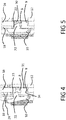
- Figure 5 shows the condition where tooth 9 has completely released seat 8 and is housed in slot 24 after occlusion mechanism 6 has rotated with respect to selectively disengageable unit 4.
- Head 22 is fully overlapped on seat 8 and, due to the biasing action of a spring 29, moves down and snaps into seat 8 to rest against sprocket 16 along the circumferential direction. Abutment of head 22 against sprocket 16 is kept by the action of spring 25 to define a retaining position of retainer 10.
- an extraction position of tooth 9 from seat 8 is kept while plunger 7 is outside seat 8.
- the operator can release handles 20 and retainer 10 keeps the angular position such that tooth 9 is out of seat 8.
- tooth 9 is circumferentially spaced from plunger 7 via a gap G (see figure 6 ).
- the operator shall switch the PTO off as soon as he or she understands that pick-up is disconnected from the PTO because the safety clutch 1 automatically switched in the disengaged position.
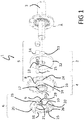
- safety clutch 1 comprises handles 20 according to figure 1
- disconnection of the PTO is the safest possible condition to guarantee that hands of the operator are not hurt when he or she grabs handles 20 and rotates disk 18 so that tooth 9 moves out from seat 8 and spring 25 is kept in a compressed state via arm 10 engaging seat 8.
- plunger 7 When clutch 1 is engaged and torque is transferred, plunger 7 is partly housed in sheath 14 and partly contacts a chamfered edge 30 of seat 8. The inclination of chamfered edge 30 is such to properly load plunger 7 to transmit torque until the maximum threshold is reached. When this happens, chamfered edge 30 applies on plunger 7 a load having a component that is parallel to the action of spring 13. The magnitude of such a component depends on the inclination of chamfered edge 30. If torque tends to further increase, the component parallel to axis A increases as well and this will cause compression of spring 13 to cause retraction of plunger 7 and disengagement of clutch 1. Therefore, preload of spring 13 sets the maximum level of torque transmitted by clutch 1.
- plunger 7 In case, by chance, plunger 7 is contacting tooth 9 and fully overlaps seat 8 when the operator has removed the blockage and decides to move occlusion mechanism 6, upon exit of tooth 9 from seat 8, plunger 7 would enter seat 8 and lift retainer 10 so that the latter is immediately disengaged from seat 8, as already mentioned in the above paragraphs.
- FIG. 7 schematically shows a trailed baler 40 powered by the PTO of a tractor (not shown).
- Power from the PTO drives a gearbox (not shown) connected to a plurality of driven functional units, such as a compacting device preferably comprising belts 41, and a pick-up or feeder 42 comprising a plurality of tines 43 movable in a predetermined path to lift crop material from the ground and deliver it towards a compacting chamber 44 of baler 40.
- pick-up 42 is in series to compacting device with respect to the gearbox.
- torque transfer from PTO to functional units is provided with a speed reduction in order to increase torque available to the functional units.
- Safety clutch 1 can be placed in any position along the torque path on the baler, depending on the intended use.
- safety clutch 1 is in series between either the functional unit or the gearbox and pick-up 42.
- a clutch according to the present invention has the following advantages.
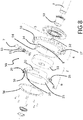
- clutch 50 is a further embodiment of a safety clutch according to the present invention. Elements and components of clutch 50 that are functionally identical to those already described in the preceding paragraphs will maintain the same reference numeral.
- Sprocket 16 of selectively disengageable unit 4 comprises a hub 52 radially supported by shaft 3 via a bushing 53.
- Seat 8 and slot 24 are radial and defined by a collar 54 rigidly connected to sprocket 16.
- sprocket 16 and collar 54 are a single body.
- Stop 27 radially projects from collar 54.
- Retainer 10 and spring 29 are attached to ring 55 as well so that head 22 reaches seat 8 through hole 23.
- the latter is radial and defined by ring 55.
- Ring 55 is axially attached to disengageable unit 4 via a flange 56 so that ring 55 is axially interposed between flange 56 and sprocket 16.
- flange 56 is attached to selectively disengageable unit 4, in particular to collar 54, via a plurality of screws.
- the operator may act on handles 20 or another manual grip or hold provided on obstruction mechanism 6.
- the operator may operate a servo-mechanism to rotate obstruction mechanism 6 with respect to selectively disengageable unit 4 to have tooth 9 exit, i.e. along the circumferential direction, from seat 8 and, thus, have clutch 1 re-engaged.
Landscapes
- Engineering & Computer Science (AREA)
- General Engineering & Computer Science (AREA)
- Mechanical Engineering (AREA)
- Life Sciences & Earth Sciences (AREA)
- Environmental Sciences (AREA)
- Soil Sciences (AREA)
- Mechanical Operated Clutches (AREA)
- Agricultural Machines (AREA)
Claims (20)
- Coupleur (1) pour outil agricole, comprenant :- une unité rotative (2) pour couplage à un arbre motorisé (3),- une unité sélectivement débrayable (4) coaxiale avec l'unité rotative (2) permettant de transférer un couple de puissance à l'intérieur de l'outil,- un limiteur de couple sans jeu (5) qui peut fonctionner :* en position engagée où un poussoir sollicité (7) est logé dans un siège (8) pour coupler angulairement l'unité rotative (2) et l'unité sélectivement débrayable (4) pour un transfert de couple jusqu'à ce que le niveau maximal du couple soit atteint ; et* une position désengagée dans laquelle le poussoir (7) sort du siège (8) ; et- un mécanisme d'obturation de sécurité (6) avec un élément obturateur (9) qui peut être sélectivement déplacé en une position obturante permettant d'empêcher le siège (8) de loger le poussoir (7) et, dans une position libérée, de permettre le couplage de forme lorsque le siège du poussoir (7) et le siège (8) se chevauchent, où le mécanisme d'obturation (6) est sollicité pour passer en position d'obturation lorsque le poussoir (7) sort du siège (8) afin d'atteindre la position désengagée lorsque le couple maximal est atteint, et peut être actionné contre la sollicitation par un opérateur afin de retourner dans la position libérée ;caractérisé en ce que le coupleur (1) comprend de plus un dispositif de retenue sollicité(10), où le dispositif de retenue sollicité (10) passe brusquement en position de retenue pour maintenir une position d'extraction de l'élément obturant (9) à partir du siège (8) lorsque le mécanisme d'obturation (6) est actionné contre la sollicitation et le poussoir (7) est en dehors du siège (8).
- Coupleur selon la revendication 1, dans lequel le dispositif de retenue (10) est libéré de la position de retenue par le poussoir sollicité (7) lorsqu'il rentre dans le siège (8) et, après la libération de la position de retenue, le dispositif de retenue (10) est tourné par la sollicitation du mécanisme d'obturation (6) afin d'abouter par chevauchement sur une surface (28) en dehors du siège (8).
- Coupleur selon la revendication 2, dans lequel, en position engagée, le poussoir (7) empêche l'élément obturateur (9) de rentrer dans le siège (8) contre l'action du mécanisme d'obturation sollicité (6).
- Coupleur selon la revendication 3, dans lequel le siège (8) est traversant pour sélectivement engager le poussoir (7) ou le dispositif de retenue (10) et dans lequel le poussoir (7) se trouve à l'opposé du dispositif de retenue (10) par rapport au siège (8).
- Coupleur selon l'une quelconque des revendications 1 à 4, dans lequel le mécanisme d'obturation (6) tourne relativement par rapport à l'unité sélectivement débrayable (4) et inclut le dispositif de retenue (10).
- Coupleur selon l'une quelconque des revendications précédentes, dans lequel après la rotation relative de l'unité rotative (2) et de l'unité sélectivement débrayable (4) en position désengagée, le poussoir (7) roule sur une surface de façon à ce que la compression et l'élongation du poussoir sollicité (7) soient sensiblement nulles.
- Coupleur selon l'une quelconque des revendications précédentes, dans lequel l'élément obturateur (9) est conçu de façon à rentrer dans le siège (8) le long d'une direction perpendiculaire à l'action du poussoir sollicité (7) lorsqu'il rentre dans le siège (8).
- Coupleur selon l'une quelconque des revendications précédentes, dans lequel le poussoir (7) est un rouleau.
- Coupleur selon la revendication 8, dans lequel l'élément obturateur (9) est une dent chevauchant le chemin de roulis du poussoir (7) en position désengagée.
- Coupleur selon l'une quelconque des revendications précédentes, dans lequel le mécanisme d'obturation (6) comprend une poignée (20) ou un moyen de préhension manuel permettant d'extraire l'élément obturateur (9) du siège (8).
- Coupleur selon l'une quelconque des revendications précédentes, dans lequel le poussoir (7) se déplace le long d'une direction sensiblement axiale permettant d'engager / désengager le siège (8).
- Coupleur selon la revendication 11, dans lequel le poussoir (7) est déporté par rapport à l'axe de rotation (A) de l'unité rotative (2).
- Coupleur selon l'une des revendications 11 ou 12, dans lequel l'élément obturateur (9) est logé dans une fente cintrée (24).
- Coupleur selon l'une quelconque des revendications 11 à 13, dans lequel le poussoir (7) est en contact avec une face sensiblement plane de l'unité sélectivement débrayable (4) ou une tête (31) de l'élément obturateur (9) lorsque l'élément obturateur (9) est en position d'obturation.
- Coupleur selon l'une quelconque des revendications 1 à 10, dans lequel le poussoir (7) se déplace le long d'une direction sensiblement radiale permettant d'engager / désengager le siège (8).
- Coupleur selon la revendication 15, dans lequel le poussoir (7) est logé dans un disque (51) de l'unité rotative (2).
- Coupleur selon l'une des revendications 15 ou 16, dans lequel l'élément obturateur (9) est logé dans une fente radiale (24).
- Coupleur selon l'une quelconque des revendications 15 à 17, dans lequel le poussoir (7) est en contact avec un collier (54) de l'unité sélectivement débrayable (4) ou une tête (31) de l'élément obturateur (9) lorsque l'élément obturateur (9) est en position d'obturation.
- Véhicule agricole ou accessoire agricole remorqué (40) comprenant un outil (42) commandé par un Coupleur de sécurité (1) selon l'une quelconque des revendications précédentes.
- Méthode d'actionnement d'un coupleur selon l'une quelconque des revendications 1 à 18, comprenant l'étape de l'actionnement du mécanisme d'obturation de sécurité (8) pour retourner en position libérée.
Applications Claiming Priority (1)
| Application Number | Priority Date | Filing Date | Title |
|---|---|---|---|
| BE2016/5746A BE1024270B1 (nl) | 2016-10-06 | 2016-10-06 | Veiligheidskoppeling voor een landbouwvoertuig of gesleept toebehoren ervan |
Publications (2)
| Publication Number | Publication Date |
|---|---|
| EP3321533A1 EP3321533A1 (fr) | 2018-05-16 |
| EP3321533B1 true EP3321533B1 (fr) | 2019-06-19 |
Family
ID=57838073
Family Applications (1)
| Application Number | Title | Priority Date | Filing Date |
|---|---|---|---|
| EP17193576.0A Active EP3321533B1 (fr) | 2016-10-06 | 2017-09-27 | Embrayage de sécurité pour véhicule agricole ou son accessoire remorqué |
Country Status (3)
| Country | Link |
|---|---|
| US (1) | US10455754B2 (fr) |
| EP (1) | EP3321533B1 (fr) |
| BE (1) | BE1024270B1 (fr) |
Families Citing this family (1)
| Publication number | Priority date | Publication date | Assignee | Title |
|---|---|---|---|---|
| EP4528121A1 (fr) * | 2023-09-25 | 2025-03-26 | CNH Industrial Belgium N.V. | Embrayage de sécurité pour véhicule agricole |
Family Cites Families (15)
| Publication number | Priority date | Publication date | Assignee | Title |
|---|---|---|---|---|
| DE441218C (de) | 1927-02-28 | Alfred Rubart | Gesteinstaub-Streuapparat | |
| US998615A (en) * | 1907-12-02 | 1911-07-25 | Cox Multi Mailer Company | Clutch. |
| US3132730A (en) * | 1960-08-31 | 1964-05-12 | Josef Y Dahlstrand | Torque disconnect safety coupling |
| GB1160062A (en) * | 1966-01-11 | 1969-07-30 | Fisholow Prod Ltd | Improvements in or relating to Overload Clutches |
| FR2316476A1 (fr) * | 1975-06-30 | 1977-01-28 | Duc Henri | Coupleur reglable d'entrainement en rotation |
| IT1070120B (it) * | 1975-09-11 | 1985-03-25 | Walterscheid Gmbh Jean | Innesto a ruota libera per la limitazione della coppia trasmessa da un motore ad una macchina operatrice |
| GB1548751A (en) * | 1976-03-17 | 1979-07-18 | Brown Sadi Sa David | Torque-limiting devices |
| US4220230A (en) * | 1979-03-30 | 1980-09-02 | Hansen Quinten A | Overload release clutch |
| DE3602282A1 (de) * | 1986-01-25 | 1987-08-20 | Ringspann Maurer Kg A | Ueberlastkupplung |
| DE4441218C2 (de) * | 1994-11-19 | 1998-07-09 | Walterscheid Gmbh Gkn | Drehmomentbegrenzungskupplung oder Freilauf |
| DE19611622C1 (de) | 1996-03-25 | 1997-07-24 | Walterscheid Gmbh Gkn | Drehmomentbegrenzungskupplung |
| DE10145430C2 (de) | 2001-09-14 | 2003-09-25 | Walterscheid Gmbh Gkn | Drehmomentbegrenzungskupplung |
| DE10201988C2 (de) * | 2002-01-21 | 2003-12-24 | Walterscheid Gmbh Gkn | Drehmomentbegrenzungskupplung |
| DE102007057865A1 (de) | 2007-11-29 | 2009-06-04 | Gkn Walterscheid Gmbh | Drehmomentbegrenzungskupplung |
| DE102009037026B4 (de) * | 2009-08-13 | 2011-07-28 | GKN Walterscheid GmbH, 53797 | Drehmomentbegrenzungskupplung |
-
2016
- 2016-10-06 BE BE2016/5746A patent/BE1024270B1/nl active IP Right Grant
-
2017
- 2017-09-27 EP EP17193576.0A patent/EP3321533B1/fr active Active
- 2017-10-06 US US15/727,294 patent/US10455754B2/en active Active
Non-Patent Citations (1)
| Title |
|---|
| None * |
Also Published As
| Publication number | Publication date |
|---|---|
| BE1024270B1 (nl) | 2018-01-10 |
| US10455754B2 (en) | 2019-10-29 |
| EP3321533A1 (fr) | 2018-05-16 |
| US20180098480A1 (en) | 2018-04-12 |
Similar Documents
| Publication | Publication Date | Title |
|---|---|---|
| CA1125198A (fr) | Organe debrayeur en cas de surcharge | |
| EP2571345B1 (fr) | Moissoneuses batteuses | |
| EP3343056A1 (fr) | Tige de poussée électrique | |
| US4071105A (en) | Coupling device for a power transmission shaft | |
| US20120129637A1 (en) | Transmission device for self-propelled equipment and self-propelled equipment fitted with such a transmission | |
| US4089396A (en) | Clutches | |
| CN104675875A (zh) | 扭矩限制器 | |
| EP3321533B1 (fr) | Embrayage de sécurité pour véhicule agricole ou son accessoire remorqué | |
| CA2358817C (fr) | Limiteur de surcharge de couple de detente | |
| EP4167709B1 (fr) | Système de protection pour arbre primaire et arbre primaire comprenant ledit système de protection | |
| EP0952027B1 (fr) | Prise de force pour véhicule agricole et procédé de mise en oeuvre associé | |
| EP3423334B1 (fr) | Équipement motorisé autotracté à capacité de virage serré | |
| GB2060339A (en) | Overload clutches | |
| KR102341958B1 (ko) | 과속 방지 기능을 갖는 토크 제한기 | |
| JPS5834092B2 (ja) | ドウリヨクカリトリキ | |
| EP2693069B1 (fr) | Embrayage d'entraînement à friction présentant des éléments en forme de rampe | |
| GB2042655A (en) | Torque Limiting Clutch | |
| DE102009015822B3 (de) | Heckenschere | |
| EP2168426A1 (fr) | Machine agricole | |
| CN107448491B (zh) | 异物卷入自动脱开式联轴器 | |
| GB2403517A (en) | A switchable freewheel coupling | |
| CZ20012679A3 (cs) | Traktor na trávu | |
| JPS5823251B2 (ja) | ジザイレンケツジクノ ドウリヨクジドウダンゾクソウチ | |
| CS232295B1 (cs) | Pojistný spojkový mechanismus | |
| CS236607B1 (cs) | Poistná zubová spojka s nastavitelným momentom |
Legal Events
| Date | Code | Title | Description |
|---|---|---|---|
| PUAI | Public reference made under article 153(3) epc to a published international application that has entered the european phase |
Free format text: ORIGINAL CODE: 0009012 |
|
| STAA | Information on the status of an ep patent application or granted ep patent |
Free format text: STATUS: THE APPLICATION HAS BEEN PUBLISHED |
|
| AK | Designated contracting states |
Kind code of ref document: A1 Designated state(s): AL AT BE BG CH CY CZ DE DK EE ES FI FR GB GR HR HU IE IS IT LI LT LU LV MC MK MT NL NO PL PT RO RS SE SI SK SM TR |
|
| AX | Request for extension of the european patent |
Extension state: BA ME |
|
| STAA | Information on the status of an ep patent application or granted ep patent |
Free format text: STATUS: REQUEST FOR EXAMINATION WAS MADE |
|
| 17P | Request for examination filed |
Effective date: 20181116 |
|
| RBV | Designated contracting states (corrected) |
Designated state(s): AL AT BE BG CH CY CZ DE DK EE ES FI FR GB GR HR HU IE IS IT LI LT LU LV MC MK MT NL NO PL PT RO RS SE SI SK SM TR |
|
| GRAP | Despatch of communication of intention to grant a patent |
Free format text: ORIGINAL CODE: EPIDOSNIGR1 |
|
| STAA | Information on the status of an ep patent application or granted ep patent |
Free format text: STATUS: GRANT OF PATENT IS INTENDED |
|
| RIC1 | Information provided on ipc code assigned before grant |
Ipc: F16D 43/206 20060101ALI20181203BHEP Ipc: F16D 7/08 20060101AFI20181203BHEP Ipc: A01F 15/08 20060101ALI20181203BHEP Ipc: F16D 43/208 20060101ALI20181203BHEP Ipc: F16D 7/10 20060101ALI20181203BHEP |
|
| INTG | Intention to grant announced |
Effective date: 20190108 |
|
| GRAS | Grant fee paid |
Free format text: ORIGINAL CODE: EPIDOSNIGR3 |
|
| GRAA | (expected) grant |
Free format text: ORIGINAL CODE: 0009210 |
|
| STAA | Information on the status of an ep patent application or granted ep patent |
Free format text: STATUS: THE PATENT HAS BEEN GRANTED |
|
| AK | Designated contracting states |
Kind code of ref document: B1 Designated state(s): AL AT BE BG CH CY CZ DE DK EE ES FI FR GB GR HR HU IE IS IT LI LT LU LV MC MK MT NL NO PL PT RO RS SE SI SK SM TR |
|
| REG | Reference to a national code |
Ref country code: GB Ref legal event code: FG4D |
|
| REG | Reference to a national code |
Ref country code: CH Ref legal event code: EP |
|
| REG | Reference to a national code |
Ref country code: IE Ref legal event code: FG4D |
|
| REG | Reference to a national code |
Ref country code: DE Ref legal event code: R096 Ref document number: 602017004636 Country of ref document: DE |
|
| REG | Reference to a national code |
Ref country code: AT Ref legal event code: REF Ref document number: 1145900 Country of ref document: AT Kind code of ref document: T Effective date: 20190715 |
|
| REG | Reference to a national code |
Ref country code: NL Ref legal event code: MP Effective date: 20190619 |
|
| PG25 | Lapsed in a contracting state [announced via postgrant information from national office to epo] |
Ref country code: HR Free format text: LAPSE BECAUSE OF FAILURE TO SUBMIT A TRANSLATION OF THE DESCRIPTION OR TO PAY THE FEE WITHIN THE PRESCRIBED TIME-LIMIT Effective date: 20190619 Ref country code: LT Free format text: LAPSE BECAUSE OF FAILURE TO SUBMIT A TRANSLATION OF THE DESCRIPTION OR TO PAY THE FEE WITHIN THE PRESCRIBED TIME-LIMIT Effective date: 20190619 Ref country code: FI Free format text: LAPSE BECAUSE OF FAILURE TO SUBMIT A TRANSLATION OF THE DESCRIPTION OR TO PAY THE FEE WITHIN THE PRESCRIBED TIME-LIMIT Effective date: 20190619 Ref country code: NO Free format text: LAPSE BECAUSE OF FAILURE TO SUBMIT A TRANSLATION OF THE DESCRIPTION OR TO PAY THE FEE WITHIN THE PRESCRIBED TIME-LIMIT Effective date: 20190919 Ref country code: SE Free format text: LAPSE BECAUSE OF FAILURE TO SUBMIT A TRANSLATION OF THE DESCRIPTION OR TO PAY THE FEE WITHIN THE PRESCRIBED TIME-LIMIT Effective date: 20190619 Ref country code: AL Free format text: LAPSE BECAUSE OF FAILURE TO SUBMIT A TRANSLATION OF THE DESCRIPTION OR TO PAY THE FEE WITHIN THE PRESCRIBED TIME-LIMIT Effective date: 20190619 |
|
| REG | Reference to a national code |
Ref country code: LT Ref legal event code: MG4D |
|
| PG25 | Lapsed in a contracting state [announced via postgrant information from national office to epo] |
Ref country code: LV Free format text: LAPSE BECAUSE OF FAILURE TO SUBMIT A TRANSLATION OF THE DESCRIPTION OR TO PAY THE FEE WITHIN THE PRESCRIBED TIME-LIMIT Effective date: 20190619 Ref country code: BG Free format text: LAPSE BECAUSE OF FAILURE TO SUBMIT A TRANSLATION OF THE DESCRIPTION OR TO PAY THE FEE WITHIN THE PRESCRIBED TIME-LIMIT Effective date: 20190919 Ref country code: RS Free format text: LAPSE BECAUSE OF FAILURE TO SUBMIT A TRANSLATION OF THE DESCRIPTION OR TO PAY THE FEE WITHIN THE PRESCRIBED TIME-LIMIT Effective date: 20190619 Ref country code: GR Free format text: LAPSE BECAUSE OF FAILURE TO SUBMIT A TRANSLATION OF THE DESCRIPTION OR TO PAY THE FEE WITHIN THE PRESCRIBED TIME-LIMIT Effective date: 20190920 |
|
| REG | Reference to a national code |
Ref country code: AT Ref legal event code: MK05 Ref document number: 1145900 Country of ref document: AT Kind code of ref document: T Effective date: 20190619 |
|
| PG25 | Lapsed in a contracting state [announced via postgrant information from national office to epo] |
Ref country code: RO Free format text: LAPSE BECAUSE OF FAILURE TO SUBMIT A TRANSLATION OF THE DESCRIPTION OR TO PAY THE FEE WITHIN THE PRESCRIBED TIME-LIMIT Effective date: 20190619 Ref country code: NL Free format text: LAPSE BECAUSE OF FAILURE TO SUBMIT A TRANSLATION OF THE DESCRIPTION OR TO PAY THE FEE WITHIN THE PRESCRIBED TIME-LIMIT Effective date: 20190619 Ref country code: CZ Free format text: LAPSE BECAUSE OF FAILURE TO SUBMIT A TRANSLATION OF THE DESCRIPTION OR TO PAY THE FEE WITHIN THE PRESCRIBED TIME-LIMIT Effective date: 20190619 Ref country code: PT Free format text: LAPSE BECAUSE OF FAILURE TO SUBMIT A TRANSLATION OF THE DESCRIPTION OR TO PAY THE FEE WITHIN THE PRESCRIBED TIME-LIMIT Effective date: 20191021 Ref country code: EE Free format text: LAPSE BECAUSE OF FAILURE TO SUBMIT A TRANSLATION OF THE DESCRIPTION OR TO PAY THE FEE WITHIN THE PRESCRIBED TIME-LIMIT Effective date: 20190619 Ref country code: SK Free format text: LAPSE BECAUSE OF FAILURE TO SUBMIT A TRANSLATION OF THE DESCRIPTION OR TO PAY THE FEE WITHIN THE PRESCRIBED TIME-LIMIT Effective date: 20190619 Ref country code: AT Free format text: LAPSE BECAUSE OF FAILURE TO SUBMIT A TRANSLATION OF THE DESCRIPTION OR TO PAY THE FEE WITHIN THE PRESCRIBED TIME-LIMIT Effective date: 20190619 |
|
| PG25 | Lapsed in a contracting state [announced via postgrant information from national office to epo] |
Ref country code: ES Free format text: LAPSE BECAUSE OF FAILURE TO SUBMIT A TRANSLATION OF THE DESCRIPTION OR TO PAY THE FEE WITHIN THE PRESCRIBED TIME-LIMIT Effective date: 20190619 Ref country code: IS Free format text: LAPSE BECAUSE OF FAILURE TO SUBMIT A TRANSLATION OF THE DESCRIPTION OR TO PAY THE FEE WITHIN THE PRESCRIBED TIME-LIMIT Effective date: 20191019 Ref country code: SM Free format text: LAPSE BECAUSE OF FAILURE TO SUBMIT A TRANSLATION OF THE DESCRIPTION OR TO PAY THE FEE WITHIN THE PRESCRIBED TIME-LIMIT Effective date: 20190619 |
|
| PG25 | Lapsed in a contracting state [announced via postgrant information from national office to epo] |
Ref country code: TR Free format text: LAPSE BECAUSE OF FAILURE TO SUBMIT A TRANSLATION OF THE DESCRIPTION OR TO PAY THE FEE WITHIN THE PRESCRIBED TIME-LIMIT Effective date: 20190619 |
|
| PG25 | Lapsed in a contracting state [announced via postgrant information from national office to epo] |
Ref country code: DK Free format text: LAPSE BECAUSE OF FAILURE TO SUBMIT A TRANSLATION OF THE DESCRIPTION OR TO PAY THE FEE WITHIN THE PRESCRIBED TIME-LIMIT Effective date: 20190619 Ref country code: PL Free format text: LAPSE BECAUSE OF FAILURE TO SUBMIT A TRANSLATION OF THE DESCRIPTION OR TO PAY THE FEE WITHIN THE PRESCRIBED TIME-LIMIT Effective date: 20190619 |
|
| PG25 | Lapsed in a contracting state [announced via postgrant information from national office to epo] |
Ref country code: MC Free format text: LAPSE BECAUSE OF FAILURE TO SUBMIT A TRANSLATION OF THE DESCRIPTION OR TO PAY THE FEE WITHIN THE PRESCRIBED TIME-LIMIT Effective date: 20190619 Ref country code: IS Free format text: LAPSE BECAUSE OF FAILURE TO SUBMIT A TRANSLATION OF THE DESCRIPTION OR TO PAY THE FEE WITHIN THE PRESCRIBED TIME-LIMIT Effective date: 20200224 |
|
| REG | Reference to a national code |
Ref country code: DE Ref legal event code: R097 Ref document number: 602017004636 Country of ref document: DE |
|
| PLBE | No opposition filed within time limit |
Free format text: ORIGINAL CODE: 0009261 |
|
| STAA | Information on the status of an ep patent application or granted ep patent |
Free format text: STATUS: NO OPPOSITION FILED WITHIN TIME LIMIT |
|
| PG2D | Information on lapse in contracting state deleted |
Ref country code: IS |
|
| PG25 | Lapsed in a contracting state [announced via postgrant information from national office to epo] |
Ref country code: LU Free format text: LAPSE BECAUSE OF NON-PAYMENT OF DUE FEES Effective date: 20190927 Ref country code: IE Free format text: LAPSE BECAUSE OF NON-PAYMENT OF DUE FEES Effective date: 20190927 |
|
| REG | Reference to a national code |
Ref country code: BE Ref legal event code: MM Effective date: 20190930 |
|
| 26N | No opposition filed |
Effective date: 20200603 |
|
| PG25 | Lapsed in a contracting state [announced via postgrant information from national office to epo] |
Ref country code: BE Free format text: LAPSE BECAUSE OF NON-PAYMENT OF DUE FEES Effective date: 20190930 Ref country code: SI Free format text: LAPSE BECAUSE OF FAILURE TO SUBMIT A TRANSLATION OF THE DESCRIPTION OR TO PAY THE FEE WITHIN THE PRESCRIBED TIME-LIMIT Effective date: 20190619 |
|
| REG | Reference to a national code |
Ref country code: CH Ref legal event code: PL |
|
| PG25 | Lapsed in a contracting state [announced via postgrant information from national office to epo] |
Ref country code: CY Free format text: LAPSE BECAUSE OF FAILURE TO SUBMIT A TRANSLATION OF THE DESCRIPTION OR TO PAY THE FEE WITHIN THE PRESCRIBED TIME-LIMIT Effective date: 20190619 |
|
| REG | Reference to a national code |
Ref country code: DE Ref legal event code: R082 Ref document number: 602017004636 Country of ref document: DE Representative=s name: KROHER STROBEL RECHTS- UND PATENTANWAELTE PART, DE |
|
| PG25 | Lapsed in a contracting state [announced via postgrant information from national office to epo] |
Ref country code: MT Free format text: LAPSE BECAUSE OF FAILURE TO SUBMIT A TRANSLATION OF THE DESCRIPTION OR TO PAY THE FEE WITHIN THE PRESCRIBED TIME-LIMIT Effective date: 20190619 Ref country code: HU Free format text: LAPSE BECAUSE OF FAILURE TO SUBMIT A TRANSLATION OF THE DESCRIPTION OR TO PAY THE FEE WITHIN THE PRESCRIBED TIME-LIMIT; INVALID AB INITIO Effective date: 20170927 |
|
| PG25 | Lapsed in a contracting state [announced via postgrant information from national office to epo] |
Ref country code: CH Free format text: LAPSE BECAUSE OF NON-PAYMENT OF DUE FEES Effective date: 20200930 Ref country code: LI Free format text: LAPSE BECAUSE OF NON-PAYMENT OF DUE FEES Effective date: 20200930 |
|
| GBPC | Gb: european patent ceased through non-payment of renewal fee |
Effective date: 20210927 |
|
| PG25 | Lapsed in a contracting state [announced via postgrant information from national office to epo] |
Ref country code: MK Free format text: LAPSE BECAUSE OF FAILURE TO SUBMIT A TRANSLATION OF THE DESCRIPTION OR TO PAY THE FEE WITHIN THE PRESCRIBED TIME-LIMIT Effective date: 20190619 |
|
| PG25 | Lapsed in a contracting state [announced via postgrant information from national office to epo] |
Ref country code: GB Free format text: LAPSE BECAUSE OF NON-PAYMENT OF DUE FEES Effective date: 20210927 |
|
| PGFP | Annual fee paid to national office [announced via postgrant information from national office to epo] |
Ref country code: DE Payment date: 20250926 Year of fee payment: 9 |
|
| PGFP | Annual fee paid to national office [announced via postgrant information from national office to epo] |
Ref country code: IT Payment date: 20250922 Year of fee payment: 9 |
|
| PGFP | Annual fee paid to national office [announced via postgrant information from national office to epo] |
Ref country code: FR Payment date: 20250925 Year of fee payment: 9 |