EP3321541B1 - Spannungswellengetriebe und spannungswellengenerator - Google Patents
Spannungswellengetriebe und spannungswellengenerator Download PDFInfo
- Publication number
- EP3321541B1 EP3321541B1 EP15897705.8A EP15897705A EP3321541B1 EP 3321541 B1 EP3321541 B1 EP 3321541B1 EP 15897705 A EP15897705 A EP 15897705A EP 3321541 B1 EP3321541 B1 EP 3321541B1
- Authority
- EP
- European Patent Office
- Prior art keywords
- wave
- inner ring
- plug
- contact part
- peripheral surface
- Prior art date
- Legal status (The legal status is an assumption and is not a legal conclusion. Google has not performed a legal analysis and makes no representation as to the accuracy of the status listed.)
- Active
Links
Images



Classifications
-
- F—MECHANICAL ENGINEERING; LIGHTING; HEATING; WEAPONS; BLASTING
- F16—ENGINEERING ELEMENTS AND UNITS; GENERAL MEASURES FOR PRODUCING AND MAINTAINING EFFECTIVE FUNCTIONING OF MACHINES OR INSTALLATIONS; THERMAL INSULATION IN GENERAL
- F16H—GEARING
- F16H1/00—Toothed gearings for conveying rotary motion
- F16H1/28—Toothed gearings for conveying rotary motion with gears having orbital motion
- F16H1/32—Toothed gearings for conveying rotary motion with gears having orbital motion in which the central axis of the gearing lies inside the periphery of an orbital gear
-
- F—MECHANICAL ENGINEERING; LIGHTING; HEATING; WEAPONS; BLASTING
- F16—ENGINEERING ELEMENTS AND UNITS; GENERAL MEASURES FOR PRODUCING AND MAINTAINING EFFECTIVE FUNCTIONING OF MACHINES OR INSTALLATIONS; THERMAL INSULATION IN GENERAL
- F16H—GEARING
- F16H49/00—Other gearings
- F16H49/001—Wave gearings, e.g. harmonic drive transmissions
-
- F—MECHANICAL ENGINEERING; LIGHTING; HEATING; WEAPONS; BLASTING
- F16—ENGINEERING ELEMENTS AND UNITS; GENERAL MEASURES FOR PRODUCING AND MAINTAINING EFFECTIVE FUNCTIONING OF MACHINES OR INSTALLATIONS; THERMAL INSULATION IN GENERAL
- F16C—SHAFTS; FLEXIBLE SHAFTS; ELEMENTS OR CRANKSHAFT MECHANISMS; ROTARY BODIES OTHER THAN GEARING ELEMENTS; BEARINGS
- F16C19/00—Bearings with rolling contact, for exclusively rotary movement
- F16C19/02—Bearings with rolling contact, for exclusively rotary movement with bearing balls essentially of the same size in one or more circular rows
- F16C19/14—Bearings with rolling contact, for exclusively rotary movement with bearing balls essentially of the same size in one or more circular rows for both radial and axial load
- F16C19/16—Bearings with rolling contact, for exclusively rotary movement with bearing balls essentially of the same size in one or more circular rows for both radial and axial load with a single row of balls
-
- F—MECHANICAL ENGINEERING; LIGHTING; HEATING; WEAPONS; BLASTING
- F16—ENGINEERING ELEMENTS AND UNITS; GENERAL MEASURES FOR PRODUCING AND MAINTAINING EFFECTIVE FUNCTIONING OF MACHINES OR INSTALLATIONS; THERMAL INSULATION IN GENERAL
- F16C—SHAFTS; FLEXIBLE SHAFTS; ELEMENTS OR CRANKSHAFT MECHANISMS; ROTARY BODIES OTHER THAN GEARING ELEMENTS; BEARINGS
- F16C33/00—Parts of bearings; Special methods for making bearings or parts thereof
- F16C33/30—Parts of ball or roller bearings
- F16C33/38—Ball cages
-
- F—MECHANICAL ENGINEERING; LIGHTING; HEATING; WEAPONS; BLASTING
- F16—ENGINEERING ELEMENTS AND UNITS; GENERAL MEASURES FOR PRODUCING AND MAINTAINING EFFECTIVE FUNCTIONING OF MACHINES OR INSTALLATIONS; THERMAL INSULATION IN GENERAL
- F16C—SHAFTS; FLEXIBLE SHAFTS; ELEMENTS OR CRANKSHAFT MECHANISMS; ROTARY BODIES OTHER THAN GEARING ELEMENTS; BEARINGS
- F16C2361/00—Apparatus or articles in engineering in general
- F16C2361/61—Toothed gear systems, e.g. support of pinion shafts
-
- F—MECHANICAL ENGINEERING; LIGHTING; HEATING; WEAPONS; BLASTING
- F16—ENGINEERING ELEMENTS AND UNITS; GENERAL MEASURES FOR PRODUCING AND MAINTAINING EFFECTIVE FUNCTIONING OF MACHINES OR INSTALLATIONS; THERMAL INSULATION IN GENERAL
- F16H—GEARING
- F16H1/00—Toothed gearings for conveying rotary motion
- F16H1/28—Toothed gearings for conveying rotary motion with gears having orbital motion
- F16H1/32—Toothed gearings for conveying rotary motion with gears having orbital motion in which the central axis of the gearing lies inside the periphery of an orbital gear
- F16H2001/324—Toothed gearings for conveying rotary motion with gears having orbital motion in which the central axis of the gearing lies inside the periphery of an orbital gear comprising two axially spaced, rigidly interconnected, orbital gears
Definitions
- the present invention relates to a wave generator of a strain wave gearing referred to as a flat type of gearing, and in particular to a wave generator provided with a plurality of, e.g., two wave bearings.
- a flat strain wave gearing as disclosed in Patent Document 1, is provided with two rigid internally toothed gears, one cylindrical flexible externally toothed gear, and one wave generator.
- the wave generator is provided with an ellipsoidally contoured rigid plug, and a wave bearing press-fitted onto the ellipsoidal external peripheral surface of the plug.
- a movement-restricting mechanism that restricts movement of the wave generator in an axial direction is attached to the wave generator.
- the movement-restricting mechanism has members that protrude in the axial direction from the both sides of the plug of the wave generator, and the members are either supported by bearings or brought into contact with plates, the bearings or plates being disposed on both sides of the wave generator, whereby the plug of the wave generator is restricted from moving in the axial direction.
- a known example of a wave generator of a flat strain wave gearing is one that is provided with two wave bearings, which is disclosed in Non-Patent Document 1.
- the two wave bearings are press-fitted onto the ellipsoidal external peripheral surface of the plug.
- the use of two wave bearings makes it possible for an externally toothed gear to reliably mesh with each of two internally toothed gears.
- Non-Patent Document 1 two wave bearings 113, 114 are fixed by press-fitting to an external peripheral surface 112 of a plug 111, as shown in FIG. 5 .
- a retainer restraint 124 is placed between these wave bearings 113, 114, and ball retainers 117, 121 are prevented from separating from both wave bearings 113, 114 in the axial direction.
- the retainer restraint 124 is a ring-shaped member having a center hole slightly larger than the external peripheral surface 112 of the plug 111, and the retainer restraint 124 faces the plug 111 and the two wave bearings 113, 114 with some clearance.
- Patent Document 1 JP 2011-110976 A
- Non-Patent Document 1 " Product Information, FR Series Component," [online] Harmonic Drive Systems, Inc., [retrieved April 9, 2015], Internet URL: http://www.hds.co.jp/products/lineup/hd/01sr07_fr_2a or http://www.hds.co.jp/english/products/lineup/hd/01sr07_fr_2a /
- DE 11 2013 004179 T5 discloses a wave generator for a flat-type strain wave gearing.
- the wave generator has a first elliptical outer circumferential surface of a first wave generator portion defined by a first elliptical curve, and a second elliptical outer circumferential surface of a second wave generator section defined by a second elliptical curve.
- Wave generators having a structure in which two wave bearings are press-fitted onto the external peripheral surface of a plug such as the wave generator disclosed in Non-Patent Document 1, present the following problems to be resolved.
- thrust force acts on the wave generator.
- thrust force acts in opposite directions as shown by arrows A and B in FIG. 5 .
- great thrust force acts on the wave bearings of the wave generator.
- the thrust force is greater than the pressure-reliant fixing force on the plug, there is a risk that the wave bearings will move in the axial direction relative to the plug.
- An object of the present invention is to provide a wave generator that can prevent or minimize wave bearing movement due to thrust force, and a strain wave gearing provided with this wave generator.
- a wave generator of a strain wave gearing which comprises an externally toothed gear (4) and first and second internally toothed gears.
- an externally toothed gear is made to flex into a non-circular shape and partially mesh with first and second internally toothed gears, and meshing positions between the externally toothed gear and the first and second internally toothed gears are moved in a circumferential direction, the wave generator being characterized by comprising:
- the plug may be deformed through pressure being exerted thereon from both sides in the direction of the center axis, whereby the inner rings of the first and second wave bearings may be crimped to the non-circular external peripheral surface.
- the inner ring contact part can be fixed to the external peripheral surface of the plug by being press-fitted to the external peripheral surface from the direction of the center axis.
- the retainer restraining part can be integrally formed in advance on the inner ring contact part.
- the inner ring contact part and the retainer restraining part can be manufactured as a single component, and can be fixed to the plug by press-fitting.
- the inner ring contact part can be formed integrally on the plug.
- a C-shaped stopper ring can be used as the retainer restraining part.
- the C-shaped stopper ring is fixed to the inner ring contact part by being fitted into an annular groove formed in the external peripheral surface of the inner ring contact part.
- strain wave gearing of the present invention is characterized by comprising:
- the inner ring contact part can be fixed to the external peripheral surface of the plug by being press-fitted to the external peripheral surface from the direction of the center axis.
- the retainer restraining part can be integrally formed in advance on the inner ring contact part.
- the inner ring contact part can be integrally formed in advance on the plug.
- a C-shaped stopper ring can be used as the retainer restraining part.
- the C-shaped stopper ring can be fixed to the inner ring contact part by being fitted into an annular groove formed in the external peripheral surface of the inner ring contact part.
- the end faces on both center-axial-directional sides of the plug are provided with first and second inner ring restraining plates, the inner ring of the first wave bearing is sandwiched between the first inner ring restraining plate and the inner ring contact part, and the inner ring of the second wave bearing is sandwiched between the second inner ring restraining plate and the inner ring contact part.
- the first and second wave bearings press-fitted to the non-circular external peripheral surface can be crimped to the non-circular external peripheral surface by exerting force on the plug from both center-axial-directional sides, and thereby deforming the plug.
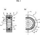
- FIG. 1(a) is a longitudinal cross-sectional view showing a flat strain wave gearing according to the present embodiment
- FIG. 1(b) is a front view of the same with part omitted.
- the flat-type strain wave gearing 1 is provided with a fixed-side internally toothed gear 2, an output-side internally toothed gear 3, a flexible externally toothed gear 4 having a cylindrical shape, and a wave generator 5.
- the internally toothed gears 2 and 3 are coaxially aligned with a slight gap therebetween in the direction of the center axis 1a.
- the externally toothed gear 4 is coaxially placed on the inner sides of the internally toothed gears 2 and 3.
- the externally toothed gear 4 has a tooth width that includes the internally toothed gears 2 and 3.
- the portion of external teeth 4a of the externally toothed gear 4 on one side in the tooth width direction faces internal teeth 2a of the first internally toothed gear 2, and the portion of the external teeth 4a on the other side faces internal teeth 3a of the second internally toothed gear 3.
- the wave generator 5 causes the externally toothed gear 4 to flex into a non-circular shape, which is an ellipsoidal shape in the present example, and to mesh with the internally toothed gears 2 and 3 at positions on a major axis L of the ellipsoidal shape.
- a non-circular shape which is an ellipsoidal shape in the present example
- the meshing positions between the externally toothed gear 4 and the internally toothed gears 2 and 3 move in a circumferential direction.
- the number of teeth of the output-side internally toothed gear 3 is 2n fewer than the number of teeth of the fixed-side internally toothed gear 2 (n being a positive integer).
- the internally toothed gear 3 and the externally toothed gear 4 have the same number of teeth. While the wave generator 5 makes one rotation, the externally toothed gear 4 rotates relative to the fixed-side internally toothed gear 2 by an angle corresponding to the difference in the number of teeth.
- the output-side internally toothed gear 3 rotates integrally with the externally toothed gear 4. The rotation of the internally toothed gear 3 is outputted toward a load member (not shown).
- FIG. 2 is a partial enlarged cross-sectional view of the flat-type strain wave gearing 1.
- the wave generator 5 is provided with a rigid plug 11, an ellipsoidal external peripheral surface 12 formed on the external peripheral surface of the plug 11, first and second wave bearings 13 and 14 bonded and fixed to the ellipsoidal external peripheral surface 12 by press-fitting from the direction of the center axis 1a, and a ring-shaped insertion member 15 placed between these wave bearings.
- the first and second wave bearings 13, 14 are coaxially aligned on the ellipsoidal external peripheral surface 12, with a slight gap left therebetween along the direction of the center axis 1a.
- the first wave bearing 13 is provided with an inner ring 16a, an outer ring 16b, a ball retainer 17 placed between these rings, and a plurality of balls 18 that are held by the ball retainer 17 so as to be free to roll and arranged in the circumferential direction with fixed gaps.
- the second wave bearing 14, having the same structure, is provided with an inner ring 19, an outer ring 20, a ball retainer 21, and balls 22.
- the insertion member 15 is positioned between the first and second wave bearings 13 and 14 along the direction of the center axis 1a.
- the insertion member 15 has a symmetrical cross-sectional shape along the direction of the center axis 1a, and the insertion member 15 is provided with a wide ring-shaped inner ring contact part 23 formed on the inner periphery of the insertion member 15, a narrow ring-shaped retainer restraining part 24 formed integrally on the outer periphery of the insertion member 15.
- Disc-shaped inner ring restraining plates 25 and 26 fixed to the outer peripheral portions of the end faces on both sides of the plug 11 are provided.
- the annular end faces on both sides of the inner ring contact part 23 of the insertion member 15 along the direction of the center axis 1a are in contact with, respectively, the annular end faces of the inner rings 16a and 19 of the first and second wave bearings 13 and 14.
- the annular end faces on both sides of the retainer restraining part 24 of the insertion member 15 along the direction of the center axis 1a respectively face the annular end faces of the ball retainers 17 and 21 of the first and second wave bearings 13 and 14 with a slight gap in between.
- the inner ring contact part 23 of the insertion member 15 is press-fitted from the direction of the center axis 1a to the ellipsoidal external peripheral surface 12 of the plug 11, and is fixed thereto by an adhesive.
- the insertion member 15 is thereby fixed to the ellipsoidal external peripheral surface 12 of the plug 11 so as to not move in the direction of the center axis 1a.
- the external peripheral edge portion of the inner ring restraining plate 25 attached to the plug 11 protrudes slightly outward in the radial direction from the ellipsoidal external peripheral surface 12 of the plug 11, and faces the annular end face of the inner ring 16a of the first wave bearing 13.
- the inner ring 16a is thereby sandwiched along the direction of the center axis 1a between the inner ring contact part 23 of the insertion member 15 and the external peripheral edge portion of the first inner ring restraining plate 25.
- the external peripheral edge portion of the other inner ring restraining plate 26 faces the annular end face of the inner ring 19 of the second wave bearing 14.
- the inner ring 19 is thereby sandwiched between the inner ring contact part 23 of the insertion member 15 and the external peripheral edge portion of the inner ring restraining plate 26.
- the movements of the bearings along the center axis 1a are inhibited by the inner ring restraining plates 25 and 26 positioned on the sides of the bearings.
- the first and second wave bearings 13 and 14 can be reliably prevented from moving from the plug 11 in the direction of the center axis 1a.
- the inner ring contact part 23 of the insertion member 15 is fixed to the plug 11 by press-fitting and an adhesive.
- the inner ring contact part 23 of the insertion member 15 can be integrally formed in the plug 11.
- FIG. 3 is a partial enlarged cross-sectional view showing a wave generator in which an inner ring contact part of an insertion member 15 is integrally formed in a plug. Because the basic configuration of the wave generator 5A shown in this drawing is the same as that of the wave generator 5 described above, the insertion member 15A is described below.
- the insertion member 15A is provided with an inner ring contact part 23A and a retainer restraining part 24A.
- the inner ring contact part 23A is an annular protrusion of a fixed thickness and fixed width that protrudes outward in the radial direction from the ellipsoidal external peripheral surface of the plug 11.
- the retainer restraining part 24A is a C-shaped stopper ring.
- the C-shaped stopper ring is fitted into an annular groove 23a formed in the circular external peripheral surface of the inner ring contact part 23A, and is thereby fixed to the inner ring contact part 23A so as to not move in the direction of the center axis 1a.
- a flat-type strain wave gearing 1A in which the wave generator 5A provided with the insertion member 15A is used, yields operative effects similar to those of the flat-type strain wave gearing 1 described above. Because the C-shaped stopper ring is fitted into the groove 23a, the work of assembling the insertion member 15A is easier than if the insertion member 15A were to be press-fitted onto the ellipsoidal external peripheral surface of the plug 11.
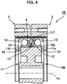
- the mechanism for inhibiting this movement can be a mechanism that crimps the inner rings 16a and 19 of the first and second wave bearings 13 and 14 to the ellipsoidal external peripheral surface 12 of the plug 11.
- the specific method involves using a punch or another tool to make dents from the direction of the center axis 1a in the external peripheral edge portions of the end faces 11a, 11b on both sides of the plug 11, deforming the portions on both sides of the ellipsoidal external peripheral surface 12 of the plug 11, and crimping the inner rings 16a and 19 to the ellipsoidal external peripheral surface 12, as shown by arrows 31 and 32 in FIG. 4 .
- the dents may be made at multiple locations at equal intervals along the circumferential direction in the outer peripheral portions of the end faces 11a and 11b.
- a strain wave gearing 1B provided with a wave generator 5B configured in this manner also yields operative effects similar to those yields when the wave generators 5 and 5A described above are used.
- the plug of the wave generator is provided with an ellipsoidal external peripheral surface, and the externally toothed gear is made to flex into an ellipsoidal shape and mesh with the internally toothed gears in two locations.
- the plug of the wave generator causes the externally toothed gear to flex into a three-lobed shape and mesh with the internally toothed gears in three locations along the circumferential direction.
- the difference in the number of teeth between the fixed-side internally toothed gear and the externally toothed gear is set to be 3n (n being a positive integer).
Landscapes
- Engineering & Computer Science (AREA)
- General Engineering & Computer Science (AREA)
- Mechanical Engineering (AREA)
- Retarders (AREA)
- Rolling Contact Bearings (AREA)
- Mounting Of Bearings Or Others (AREA)
Claims (6)
- Wellbewegungsgenerator (5) für ein Verformungswellgetriebe (1), das ein außenverzahntes Zahnrad (4) und ein erstes und zweites innenverzahntes Zahnrad (2, 3) aufweist, wobei der Wellbewegungsgenerator (5) dazu ausgebildet ist, ein außenverzahntes Zahnrad (4) in eine nicht kreisförmige Form zu biegen und in partiellen Eingriff mit dem ersten und zweiten innenverzahnten Zahnrad (2, 3) zu bringen sowie zu veranlassen, dass sich Eingriffspositionen zwischen dem außenverzahnten Zahnrad (4) und dem ersten und zweiten innenverzahnten Zahnrad (2, 3) in einer Umfangsrichtung bewegen, wobei der Wellbewegungsgenerator (5, 5A) aufweist:einen starren Stopfen (11);eine nicht kreisförmige Außenumfangsfläche (12), die auf einer Außenumfangsfläche (12) des Stopfens (11) gebildet ist;ein erstes und ein zweites Wellbewegungslager (13, 14), die auf die nicht kreisförmige Außenumfangsfläche (12) aufgepresst sind; undein Einsatzelement (15);wobei das erste und das zweite Wellbewegungslager (13, 14) mit einem vorbestimmten Spalt dazwischen entlang einer Richtung einer Mittelachse (1a) des Stopfens (11) angeordnet sind;wobei das Einsatzelement (15, 15A) zwischen dem ersten und dem zweiten Wellbewegungslager (13, 14) entlang der Richtung der Mittelachse (1a) angeordnet ist;wobei das Einsatzelement (15, 15A) einen Innenring-Kontaktteil (23) und einen Halter-Rückhalteteil (24) aufweist;wobei der Innenring-Kontaktteil (23) mit jeweiligen Innenringen (16a, 19) des ersten und des zweiten Wellbewegungslagers (13, 14) aus der Richtung der Mittelachse (1a) in Kontakt steht;wobei der Halter-Rückhalteteil (24) jeweiligen Kugelrückhaltern (17, 21) des ersten und des zweiten Wellbewegungslagers (13, 14) aus der Richtung der Mittelachse (1a) zugewandt ist;dadurch gekennzeichnet,dass der Innenring-Kontaktteil (23) entweder in dem Stopfen (11) einstückig ausgebildet ist oder an der Außenumfangsfläche (12) des Stopfens (11) derart befestigt ist, dass er sich nicht in der Richtung der Mittelachse (1a) bewegt; unddass der Halter-Rückhalteteil (24) entweder in dem Innenring-Kontaktteil (23) einstückig ausgebildet ist oder an dem Innenring-Kontaktteil (23) derart befestigt ist, dass er sich nicht in der Richtung der Mittelachse (1a) bewegt.
- Wellbewegungsgenerator (5) des Verformungswellgetriebes (1) nach Anspruch 1,
wobei der Innenring-Kontaktteil (23) an der Außenumfangsfläche (12) des Stopfens (11) durch Presspassung auf die Außenumfangsfläche aus der Richtung der Mittelachse (1a) befestigt ist, und
wobei der Halter-Rückhalteteil (24) an dem Innenring-Kontaktteil (23) einstückig ausgebildet ist. - Wellbewegungsgenerator (5, 5A) des Verformungswellgetriebes (1) nach Anspruch 1,
wobei der Innenring-Kontaktteil (23A) an dem Stopfen (11) einstückig ausgebildet ist,
wobei der Halter-Rückhalteteil (24A) ein C-förmiger Anschlagring ist, und wobei der C-förmige Anschlagring an dem Innenring-Kontaktteil (23A) durch Einpassen in eine Ringnut (23a) befestigt ist, die in einer Außenumfangsfläche (12) des Innenring-Kontaktteils (23A) gebildet ist. - Wellbewegungsgenerator (5, 5A) des Verformungswellgetriebes (1) nach Anspruch 1,
weiterhin aufweisend:eine erste und eine zweite Innenring-Rückhalteplatte (25, 26), die jeweils an Endflächen (11a, 11b) an beiden Axialrichtungsseiten des Stopfens (11) angebracht sind,wobei der Innenring (16a) des ersten Wellbewegungslagers (13) zwischen der ersten Innenring-Rückhalteplatte (25) und dem Innenring-Kontaktteil (23) sandwichartig angeordnet ist, undwobei der Innenring (19) des zweiten Wellbewegungslagers (14) zwischen der zweiten Innenring-Rückhalteplatte (26) und dem Innenring-Kontaktteil (23) sandwichartig angeordnet ist. - Wellbewegungsgenerator (5) des Verformungswellgetriebes (1) nach Anspruch 1,
wobei das erste und das zweite Wellbewegungslager (13, 14) durch Verformen des Stopfens (11) durch Druck, der von beiden Seiten in Richtung der Mittelachse (1a) auf diesen aufgebracht wird, auf die nicht kreisförmige Außenumfangsfläche (12) gecrimpt sind. - Verformungswellgetriebe (1), aufweisend:ein steifes erstes innenverzahntes Zahnrad (2);ein steifes zweites innenverzahntes Zahnrad (3), das dem ersten innenverzahnten Zahnrad koaxial benachbart angeordnet ist;ein flexibles außenverzahntes Zahnrad (4), das koaxial an Innenseiten des ersten und des zweiten innenverzahnten Zahnrads (2, 3) angeordnet ist undmit dem ersten und dem zweiten innenverzahnten Zahnrad (2, 3) kämmen kann;undeinen Wellbewegungsgenerator (5, 5A) nach einem der Ansprüche 1 bis 5, der das außenverzahnte Zahnrad (4) veranlasst, sich in eine nicht kreisförmige Form zu biegen und mit dem ersten und dem zweiten innenverzahnten Zahnrad (2, 3) partiell zu kämmen, und der bewirkt, dass sich Eingriffspositionen zwischen dem außenverzahnten Zahnrad (4) und dem ersten und zweiten innenverzahnten Zahnrad (2, 3) in einer Umfangsrichtung bewegen.
Applications Claiming Priority (1)
| Application Number | Priority Date | Filing Date | Title |
|---|---|---|---|
| PCT/JP2015/069570 WO2017006442A1 (ja) | 2015-07-07 | 2015-07-07 | 波動歯車装置および波動発生器 |
Publications (3)
| Publication Number | Publication Date |
|---|---|
| EP3321541A1 EP3321541A1 (de) | 2018-05-16 |
| EP3321541A4 EP3321541A4 (de) | 2019-03-13 |
| EP3321541B1 true EP3321541B1 (de) | 2020-04-15 |
Family
ID=57685197
Family Applications (1)
| Application Number | Title | Priority Date | Filing Date |
|---|---|---|---|
| EP15897705.8A Active EP3321541B1 (de) | 2015-07-07 | 2015-07-07 | Spannungswellengetriebe und spannungswellengenerator |
Country Status (7)
| Country | Link |
|---|---|
| US (1) | US10634230B2 (de) |
| EP (1) | EP3321541B1 (de) |
| JP (1) | JP6400200B2 (de) |
| KR (1) | KR102028056B1 (de) |
| CN (1) | CN107850187B (de) |
| TW (1) | TWI689670B (de) |
| WO (1) | WO2017006442A1 (de) |
Families Citing this family (5)
| Publication number | Priority date | Publication date | Assignee | Title |
|---|---|---|---|---|
| US11486481B2 (en) * | 2018-08-30 | 2022-11-01 | Harmonic Drive Systems Inc. | Wave generator for strain wave gearing |
| JP7414375B2 (ja) * | 2019-10-28 | 2024-01-16 | 住友重機械工業株式会社 | 撓み噛合い式歯車装置 |
| TWI739356B (zh) * | 2020-03-24 | 2021-09-11 | 東元電機股份有限公司 | 傳動裝置 |
| KR102579863B1 (ko) * | 2021-12-13 | 2023-09-19 | 주식회사 뉴로메카 | 혼합 변형 파동 기어 시스템 및 이의 조립체 |
| JP2024152380A (ja) * | 2023-04-14 | 2024-10-25 | 住友重機械工業株式会社 | 撓み噛合い式歯車装置 |
Family Cites Families (21)
| Publication number | Priority date | Publication date | Assignee | Title |
|---|---|---|---|---|
| JP2503027B2 (ja) * | 1987-09-21 | 1996-06-05 | 株式会社ハーモニック・ドライブ・システムズ | 撓みかみ合い式歯車装置 |
| JPH0438123Y2 (de) * | 1988-03-11 | 1992-09-07 | ||
| US5417186A (en) * | 1993-06-28 | 1995-05-23 | Clemson University | Dual-acting apparatus for variable valve timing and the like |
| JPH0719239A (ja) * | 1993-06-29 | 1995-01-20 | Koyo Seiko Co Ltd | 複列玉軸受 |
| JP3422078B2 (ja) * | 1994-06-23 | 2003-06-30 | 三菱電機株式会社 | 減速機 |
| JP3916101B2 (ja) * | 1997-09-09 | 2007-05-16 | 株式会社ハーモニック・ドライブ・システムズ | 撓み噛み合い式歯車装置 |
| EP1764530B1 (de) * | 2004-07-02 | 2012-03-28 | Honda Motor Co., Ltd. | Antriebseinheit mit untersetzungsgetriebe |
| CN2886215Y (zh) * | 2006-04-26 | 2007-04-04 | 哈尔滨工业大学 | 环型谐波齿轮减速器 |
| JP2008025687A (ja) * | 2006-07-20 | 2008-02-07 | Nsk Ltd | 波動歯車装置用軸受 |
| JP4948479B2 (ja) * | 2008-06-26 | 2012-06-06 | 株式会社ハーモニック・ドライブ・システムズ | 複合型波動歯車減速機 |
| JP2011110976A (ja) | 2009-11-24 | 2011-06-09 | Jtekt Corp | 伝達比可変装置 |
| US9425712B2 (en) * | 2011-09-16 | 2016-08-23 | Harmonic Drive Systems Inc. | Vibration power-generating strain wave gearing |
| JP5950649B2 (ja) * | 2012-03-23 | 2016-07-13 | キヤノン株式会社 | 波動歯車装置 |
| JP6030981B2 (ja) * | 2013-03-27 | 2016-11-24 | 株式会社三共製作所 | 波動歯車装置 |
| WO2014181375A1 (ja) * | 2013-05-08 | 2014-11-13 | 株式会社ハーモニック・ドライブ・システムズ | 波動歯車装置の波動発生器 |
| US9341252B2 (en) * | 2013-07-10 | 2016-05-17 | Harmonic Drive Systems Inc. | Wave generator and strain wave gearing |
| US9360098B2 (en) * | 2013-10-29 | 2016-06-07 | Roopnarine | Strain wave drive with improved performance |
| KR101700726B1 (ko) * | 2013-11-19 | 2017-01-31 | 가부시키가이샤 하모닉 드라이브 시스템즈 | 파동기어장치, 마찰결합식의 파동장치 및 파동발생기 |
| JP6218691B2 (ja) * | 2014-07-23 | 2017-10-25 | 株式会社ハーモニック・ドライブ・システムズ | デュアルタイプの波動歯車装置 |
| JP6934858B2 (ja) * | 2015-08-03 | 2021-09-15 | オバロ ゲーエムベーハー | 特に膨張ストローク及び/又は圧縮比を調節する内燃機関の調節軸へ連結するためのアクチュエータ |
| JP6644447B2 (ja) * | 2015-12-11 | 2020-02-12 | 株式会社ハーモニック・ドライブ・システムズ | フラット型波動歯車装置 |
-
2015
- 2015-07-07 JP JP2017527017A patent/JP6400200B2/ja active Active
- 2015-07-07 CN CN201580081224.2A patent/CN107850187B/zh active Active
- 2015-07-07 EP EP15897705.8A patent/EP3321541B1/de active Active
- 2015-07-07 KR KR1020187000367A patent/KR102028056B1/ko active Active
- 2015-07-07 US US15/740,183 patent/US10634230B2/en active Active
- 2015-07-07 WO PCT/JP2015/069570 patent/WO2017006442A1/ja not_active Ceased
-
2016
- 2016-05-23 TW TW105115984A patent/TWI689670B/zh active
Non-Patent Citations (1)
| Title |
|---|
| None * |
Also Published As
| Publication number | Publication date |
|---|---|
| TWI689670B (zh) | 2020-04-01 |
| WO2017006442A1 (ja) | 2017-01-12 |
| US20180187764A1 (en) | 2018-07-05 |
| EP3321541A1 (de) | 2018-05-16 |
| US10634230B2 (en) | 2020-04-28 |
| KR20180015734A (ko) | 2018-02-13 |
| TW201712249A (en) | 2017-04-01 |
| KR102028056B1 (ko) | 2019-10-02 |
| CN107850187A (zh) | 2018-03-27 |
| JP6400200B2 (ja) | 2018-10-03 |
| JPWO2017006442A1 (ja) | 2018-03-29 |
| EP3321541A4 (de) | 2019-03-13 |
| CN107850187B (zh) | 2020-05-05 |
Similar Documents
| Publication | Publication Date | Title |
|---|---|---|
| EP3321541B1 (de) | Spannungswellengetriebe und spannungswellengenerator | |
| KR20180052596A (ko) | 토크 변동 억제 장치, 토크 컨버터 및 동력 전달 장치 | |
| EP3388713B1 (de) | Flachdehnungswellengetriebe | |
| US9017213B2 (en) | Fastening structure of ring gear | |
| EP2508776A2 (de) | Untersetzungsgetriebe | |
| EP3150874B1 (de) | Lagervorrichtung und fixierplatte für bördelvorrichtung | |
| US9829071B2 (en) | Wobble removal shaft coupling and hypocycloid reduction gear device using same | |
| EP3141777A1 (de) | Wellengenerator für wellengetriebevorrichtung und herstellungsverfahren für wellengenerator | |
| US10718420B2 (en) | Wave generator and strain wave gearing | |
| EP2573426B1 (de) | Befestigungsstruktur für einen zahnkranz | |
| JP6212810B2 (ja) | チェーン式無段変速機 | |
| EP3106697A1 (de) | Kupplung zur verhinderung von gegenläufiger eingabe | |
| WO2015182617A1 (ja) | 軸受装置及び軸受装置用固定プレート | |
| JP6063422B2 (ja) | 位相ずれ許容動力伝達機構及び変速機構 | |
| JP5859811B2 (ja) | 逆入力防止クラッチ | |
| EP2600034A1 (de) | Antriebszugmechanismus | |
| JP2022147480A (ja) | 逆入力遮断クラッチおよびこれを備えるクラッチユニット | |
| JP6644612B2 (ja) | 転がり軸受装置 | |
| CN112728013B (zh) | 挠曲啮合式齿轮装置 | |
| JP7201444B2 (ja) | 逆入力防止クラッチ | |
| JP2007211797A (ja) | 逆入力防止クラッチ | |
| EP4428390A1 (de) | Spannungswellengetriebevorrichtung | |
| JP2018074833A (ja) | 電動アクチュエータ用回転駆動源および電動アクチュエータ | |
| JP6186633B2 (ja) | 動力伝達部材、並びに、モータ内蔵ローラ | |
| JP2016061336A (ja) | 位相ずれ許容動力伝達機構及び変速機構 |
Legal Events
| Date | Code | Title | Description |
|---|---|---|---|
| STAA | Information on the status of an ep patent application or granted ep patent |
Free format text: STATUS: THE INTERNATIONAL PUBLICATION HAS BEEN MADE |
|
| PUAI | Public reference made under article 153(3) epc to a published international application that has entered the european phase |
Free format text: ORIGINAL CODE: 0009012 |
|
| STAA | Information on the status of an ep patent application or granted ep patent |
Free format text: STATUS: REQUEST FOR EXAMINATION WAS MADE |
|
| 17P | Request for examination filed |
Effective date: 20180205 |
|
| AK | Designated contracting states |
Kind code of ref document: A1 Designated state(s): AL AT BE BG CH CY CZ DE DK EE ES FI FR GB GR HR HU IE IS IT LI LT LU LV MC MK MT NL NO PL PT RO RS SE SI SK SM TR |
|
| AX | Request for extension of the european patent |
Extension state: BA ME |
|
| DAV | Request for validation of the european patent (deleted) | ||
| DAX | Request for extension of the european patent (deleted) | ||
| A4 | Supplementary search report drawn up and despatched |
Effective date: 20190212 |
|
| RIC1 | Information provided on ipc code assigned before grant |
Ipc: F16H 49/00 20060101AFI20190206BHEP |
|
| REG | Reference to a national code |
Ref country code: DE Ref legal event code: R079 Ref document number: 602015050937 Country of ref document: DE Free format text: PREVIOUS MAIN CLASS: F16H0001320000 Ipc: F16H0049000000 |
|
| GRAP | Despatch of communication of intention to grant a patent |
Free format text: ORIGINAL CODE: EPIDOSNIGR1 |
|
| STAA | Information on the status of an ep patent application or granted ep patent |
Free format text: STATUS: GRANT OF PATENT IS INTENDED |
|
| RIC1 | Information provided on ipc code assigned before grant |
Ipc: F16H 49/00 20060101AFI20191014BHEP |
|
| INTG | Intention to grant announced |
Effective date: 20191029 |
|
| GRAS | Grant fee paid |
Free format text: ORIGINAL CODE: EPIDOSNIGR3 |
|
| GRAA | (expected) grant |
Free format text: ORIGINAL CODE: 0009210 |
|
| STAA | Information on the status of an ep patent application or granted ep patent |
Free format text: STATUS: THE PATENT HAS BEEN GRANTED |
|
| AK | Designated contracting states |
Kind code of ref document: B1 Designated state(s): AL AT BE BG CH CY CZ DE DK EE ES FI FR GB GR HR HU IE IS IT LI LT LU LV MC MK MT NL NO PL PT RO RS SE SI SK SM TR |
|
| REG | Reference to a national code |
Ref country code: CH Ref legal event code: EP |
|
| REG | Reference to a national code |
Ref country code: DE Ref legal event code: R096 Ref document number: 602015050937 Country of ref document: DE |
|
| REG | Reference to a national code |
Ref country code: IE Ref legal event code: FG4D |
|
| REG | Reference to a national code |
Ref country code: AT Ref legal event code: REF Ref document number: 1257686 Country of ref document: AT Kind code of ref document: T Effective date: 20200515 |
|
| REG | Reference to a national code |
Ref country code: NL Ref legal event code: MP Effective date: 20200415 |
|
| REG | Reference to a national code |
Ref country code: LT Ref legal event code: MG4D |
|
| PG25 | Lapsed in a contracting state [announced via postgrant information from national office to epo] |
Ref country code: IS Free format text: LAPSE BECAUSE OF FAILURE TO SUBMIT A TRANSLATION OF THE DESCRIPTION OR TO PAY THE FEE WITHIN THE PRESCRIBED TIME-LIMIT Effective date: 20200815 Ref country code: FI Free format text: LAPSE BECAUSE OF FAILURE TO SUBMIT A TRANSLATION OF THE DESCRIPTION OR TO PAY THE FEE WITHIN THE PRESCRIBED TIME-LIMIT Effective date: 20200415 Ref country code: PT Free format text: LAPSE BECAUSE OF FAILURE TO SUBMIT A TRANSLATION OF THE DESCRIPTION OR TO PAY THE FEE WITHIN THE PRESCRIBED TIME-LIMIT Effective date: 20200817 Ref country code: SE Free format text: LAPSE BECAUSE OF FAILURE TO SUBMIT A TRANSLATION OF THE DESCRIPTION OR TO PAY THE FEE WITHIN THE PRESCRIBED TIME-LIMIT Effective date: 20200415 Ref country code: NL Free format text: LAPSE BECAUSE OF FAILURE TO SUBMIT A TRANSLATION OF THE DESCRIPTION OR TO PAY THE FEE WITHIN THE PRESCRIBED TIME-LIMIT Effective date: 20200415 Ref country code: LT Free format text: LAPSE BECAUSE OF FAILURE TO SUBMIT A TRANSLATION OF THE DESCRIPTION OR TO PAY THE FEE WITHIN THE PRESCRIBED TIME-LIMIT Effective date: 20200415 Ref country code: NO Free format text: LAPSE BECAUSE OF FAILURE TO SUBMIT A TRANSLATION OF THE DESCRIPTION OR TO PAY THE FEE WITHIN THE PRESCRIBED TIME-LIMIT Effective date: 20200715 Ref country code: GR Free format text: LAPSE BECAUSE OF FAILURE TO SUBMIT A TRANSLATION OF THE DESCRIPTION OR TO PAY THE FEE WITHIN THE PRESCRIBED TIME-LIMIT Effective date: 20200716 |
|
| REG | Reference to a national code |
Ref country code: AT Ref legal event code: MK05 Ref document number: 1257686 Country of ref document: AT Kind code of ref document: T Effective date: 20200415 |
|
| PG25 | Lapsed in a contracting state [announced via postgrant information from national office to epo] |
Ref country code: BG Free format text: LAPSE BECAUSE OF FAILURE TO SUBMIT A TRANSLATION OF THE DESCRIPTION OR TO PAY THE FEE WITHIN THE PRESCRIBED TIME-LIMIT Effective date: 20200715 Ref country code: RS Free format text: LAPSE BECAUSE OF FAILURE TO SUBMIT A TRANSLATION OF THE DESCRIPTION OR TO PAY THE FEE WITHIN THE PRESCRIBED TIME-LIMIT Effective date: 20200415 Ref country code: HR Free format text: LAPSE BECAUSE OF FAILURE TO SUBMIT A TRANSLATION OF THE DESCRIPTION OR TO PAY THE FEE WITHIN THE PRESCRIBED TIME-LIMIT Effective date: 20200415 Ref country code: LV Free format text: LAPSE BECAUSE OF FAILURE TO SUBMIT A TRANSLATION OF THE DESCRIPTION OR TO PAY THE FEE WITHIN THE PRESCRIBED TIME-LIMIT Effective date: 20200415 |
|
| PG25 | Lapsed in a contracting state [announced via postgrant information from national office to epo] |
Ref country code: AL Free format text: LAPSE BECAUSE OF FAILURE TO SUBMIT A TRANSLATION OF THE DESCRIPTION OR TO PAY THE FEE WITHIN THE PRESCRIBED TIME-LIMIT Effective date: 20200415 |
|
| REG | Reference to a national code |
Ref country code: DE Ref legal event code: R097 Ref document number: 602015050937 Country of ref document: DE |
|
| PG25 | Lapsed in a contracting state [announced via postgrant information from national office to epo] |
Ref country code: AT Free format text: LAPSE BECAUSE OF FAILURE TO SUBMIT A TRANSLATION OF THE DESCRIPTION OR TO PAY THE FEE WITHIN THE PRESCRIBED TIME-LIMIT Effective date: 20200415 Ref country code: ES Free format text: LAPSE BECAUSE OF FAILURE TO SUBMIT A TRANSLATION OF THE DESCRIPTION OR TO PAY THE FEE WITHIN THE PRESCRIBED TIME-LIMIT Effective date: 20200415 Ref country code: DK Free format text: LAPSE BECAUSE OF FAILURE TO SUBMIT A TRANSLATION OF THE DESCRIPTION OR TO PAY THE FEE WITHIN THE PRESCRIBED TIME-LIMIT Effective date: 20200415 Ref country code: SM Free format text: LAPSE BECAUSE OF FAILURE TO SUBMIT A TRANSLATION OF THE DESCRIPTION OR TO PAY THE FEE WITHIN THE PRESCRIBED TIME-LIMIT Effective date: 20200415 Ref country code: EE Free format text: LAPSE BECAUSE OF FAILURE TO SUBMIT A TRANSLATION OF THE DESCRIPTION OR TO PAY THE FEE WITHIN THE PRESCRIBED TIME-LIMIT Effective date: 20200415 Ref country code: RO Free format text: LAPSE BECAUSE OF FAILURE TO SUBMIT A TRANSLATION OF THE DESCRIPTION OR TO PAY THE FEE WITHIN THE PRESCRIBED TIME-LIMIT Effective date: 20200415 Ref country code: IT Free format text: LAPSE BECAUSE OF FAILURE TO SUBMIT A TRANSLATION OF THE DESCRIPTION OR TO PAY THE FEE WITHIN THE PRESCRIBED TIME-LIMIT Effective date: 20200415 Ref country code: CZ Free format text: LAPSE BECAUSE OF FAILURE TO SUBMIT A TRANSLATION OF THE DESCRIPTION OR TO PAY THE FEE WITHIN THE PRESCRIBED TIME-LIMIT Effective date: 20200415 |
|
| PLBE | No opposition filed within time limit |
Free format text: ORIGINAL CODE: 0009261 |
|
| STAA | Information on the status of an ep patent application or granted ep patent |
Free format text: STATUS: NO OPPOSITION FILED WITHIN TIME LIMIT |
|
| PG25 | Lapsed in a contracting state [announced via postgrant information from national office to epo] |
Ref country code: MC Free format text: LAPSE BECAUSE OF FAILURE TO SUBMIT A TRANSLATION OF THE DESCRIPTION OR TO PAY THE FEE WITHIN THE PRESCRIBED TIME-LIMIT Effective date: 20200415 Ref country code: SK Free format text: LAPSE BECAUSE OF FAILURE TO SUBMIT A TRANSLATION OF THE DESCRIPTION OR TO PAY THE FEE WITHIN THE PRESCRIBED TIME-LIMIT Effective date: 20200415 Ref country code: PL Free format text: LAPSE BECAUSE OF FAILURE TO SUBMIT A TRANSLATION OF THE DESCRIPTION OR TO PAY THE FEE WITHIN THE PRESCRIBED TIME-LIMIT Effective date: 20200415 |
|
| REG | Reference to a national code |
Ref country code: CH Ref legal event code: PL |
|
| 26N | No opposition filed |
Effective date: 20210118 |
|
| GBPC | Gb: european patent ceased through non-payment of renewal fee |
Effective date: 20200715 |
|
| REG | Reference to a national code |
Ref country code: BE Ref legal event code: MM Effective date: 20200731 |
|
| PG25 | Lapsed in a contracting state [announced via postgrant information from national office to epo] |
Ref country code: IE Free format text: LAPSE BECAUSE OF NON-PAYMENT OF DUE FEES Effective date: 20200707 Ref country code: GB Free format text: LAPSE BECAUSE OF NON-PAYMENT OF DUE FEES Effective date: 20200715 Ref country code: CH Free format text: LAPSE BECAUSE OF NON-PAYMENT OF DUE FEES Effective date: 20200731 Ref country code: FR Free format text: LAPSE BECAUSE OF NON-PAYMENT OF DUE FEES Effective date: 20200731 Ref country code: LU Free format text: LAPSE BECAUSE OF NON-PAYMENT OF DUE FEES Effective date: 20200707 Ref country code: LI Free format text: LAPSE BECAUSE OF NON-PAYMENT OF DUE FEES Effective date: 20200731 |
|
| PG25 | Lapsed in a contracting state [announced via postgrant information from national office to epo] |
Ref country code: SI Free format text: LAPSE BECAUSE OF FAILURE TO SUBMIT A TRANSLATION OF THE DESCRIPTION OR TO PAY THE FEE WITHIN THE PRESCRIBED TIME-LIMIT Effective date: 20200415 Ref country code: BE Free format text: LAPSE BECAUSE OF NON-PAYMENT OF DUE FEES Effective date: 20200731 |
|
| PG25 | Lapsed in a contracting state [announced via postgrant information from national office to epo] |
Ref country code: TR Free format text: LAPSE BECAUSE OF FAILURE TO SUBMIT A TRANSLATION OF THE DESCRIPTION OR TO PAY THE FEE WITHIN THE PRESCRIBED TIME-LIMIT Effective date: 20200415 Ref country code: MT Free format text: LAPSE BECAUSE OF FAILURE TO SUBMIT A TRANSLATION OF THE DESCRIPTION OR TO PAY THE FEE WITHIN THE PRESCRIBED TIME-LIMIT Effective date: 20200415 Ref country code: CY Free format text: LAPSE BECAUSE OF FAILURE TO SUBMIT A TRANSLATION OF THE DESCRIPTION OR TO PAY THE FEE WITHIN THE PRESCRIBED TIME-LIMIT Effective date: 20200415 |
|
| PG25 | Lapsed in a contracting state [announced via postgrant information from national office to epo] |
Ref country code: MK Free format text: LAPSE BECAUSE OF FAILURE TO SUBMIT A TRANSLATION OF THE DESCRIPTION OR TO PAY THE FEE WITHIN THE PRESCRIBED TIME-LIMIT Effective date: 20200415 |
|
| PGFP | Annual fee paid to national office [announced via postgrant information from national office to epo] |
Ref country code: DE Payment date: 20250722 Year of fee payment: 11 |