EP3321568A1 - Seitlich gestützte leuchten - Google Patents
Seitlich gestützte leuchten Download PDFInfo
- Publication number
- EP3321568A1 EP3321568A1 EP17200541.5A EP17200541A EP3321568A1 EP 3321568 A1 EP3321568 A1 EP 3321568A1 EP 17200541 A EP17200541 A EP 17200541A EP 3321568 A1 EP3321568 A1 EP 3321568A1
- Authority
- EP
- European Patent Office
- Prior art keywords
- rods
- light
- hangers
- bar
- wings
- Prior art date
- Legal status (The legal status is an assumption and is not a legal conclusion. Google has not performed a legal analysis and makes no representation as to the accuracy of the status listed.)
- Granted
Links
Images










Classifications
-
- F—MECHANICAL ENGINEERING; LIGHTING; HEATING; WEAPONS; BLASTING
- F21—LIGHTING
- F21V—FUNCTIONAL FEATURES OR DETAILS OF LIGHTING DEVICES OR SYSTEMS THEREOF; STRUCTURAL COMBINATIONS OF LIGHTING DEVICES WITH OTHER ARTICLES, NOT OTHERWISE PROVIDED FOR
- F21V21/00—Supporting, suspending, or attaching arrangements for lighting devices; Hand grips
- F21V21/34—Supporting elements displaceable along a guiding element
- F21V21/35—Supporting elements displaceable along a guiding element with direct electrical contact between the supporting element and electric conductors running along the guiding element
-
- F—MECHANICAL ENGINEERING; LIGHTING; HEATING; WEAPONS; BLASTING
- F21—LIGHTING
- F21S—NON-PORTABLE LIGHTING DEVICES; SYSTEMS THEREOF; VEHICLE LIGHTING DEVICES SPECIALLY ADAPTED FOR VEHICLE EXTERIORS
- F21S8/00—Lighting devices intended for fixed installation
- F21S8/04—Lighting devices intended for fixed installation intended only for mounting on a ceiling or the like overhead structures
- F21S8/06—Lighting devices intended for fixed installation intended only for mounting on a ceiling or the like overhead structures by suspension
- F21S8/061—Lighting devices intended for fixed installation intended only for mounting on a ceiling or the like overhead structures by suspension with a non-rigid pendant, i.e. a cable, wire or chain
-
- F—MECHANICAL ENGINEERING; LIGHTING; HEATING; WEAPONS; BLASTING
- F21—LIGHTING
- F21S—NON-PORTABLE LIGHTING DEVICES; SYSTEMS THEREOF; VEHICLE LIGHTING DEVICES SPECIALLY ADAPTED FOR VEHICLE EXTERIORS
- F21S8/00—Lighting devices intended for fixed installation
- F21S8/04—Lighting devices intended for fixed installation intended only for mounting on a ceiling or the like overhead structures
- F21S8/06—Lighting devices intended for fixed installation intended only for mounting on a ceiling or the like overhead structures by suspension
- F21S8/063—Lighting devices intended for fixed installation intended only for mounting on a ceiling or the like overhead structures by suspension with a rigid pendant, i.e. a pipe or rod
-
- F—MECHANICAL ENGINEERING; LIGHTING; HEATING; WEAPONS; BLASTING
- F21—LIGHTING
- F21S—NON-PORTABLE LIGHTING DEVICES; SYSTEMS THEREOF; VEHICLE LIGHTING DEVICES SPECIALLY ADAPTED FOR VEHICLE EXTERIORS
- F21S8/00—Lighting devices intended for fixed installation
- F21S8/04—Lighting devices intended for fixed installation intended only for mounting on a ceiling or the like overhead structures
- F21S8/06—Lighting devices intended for fixed installation intended only for mounting on a ceiling or the like overhead structures by suspension
- F21S8/066—Lighting devices intended for fixed installation intended only for mounting on a ceiling or the like overhead structures by suspension from a light track
-
- F—MECHANICAL ENGINEERING; LIGHTING; HEATING; WEAPONS; BLASTING
- F21—LIGHTING
- F21V—FUNCTIONAL FEATURES OR DETAILS OF LIGHTING DEVICES OR SYSTEMS THEREOF; STRUCTURAL COMBINATIONS OF LIGHTING DEVICES WITH OTHER ARTICLES, NOT OTHERWISE PROVIDED FOR
- F21V21/00—Supporting, suspending, or attaching arrangements for lighting devices; Hand grips
- F21V21/08—Devices for easy attachment to any desired place, e.g. clip, clamp, magnet
-
- F—MECHANICAL ENGINEERING; LIGHTING; HEATING; WEAPONS; BLASTING
- F21—LIGHTING
- F21V—FUNCTIONAL FEATURES OR DETAILS OF LIGHTING DEVICES OR SYSTEMS THEREOF; STRUCTURAL COMBINATIONS OF LIGHTING DEVICES WITH OTHER ARTICLES, NOT OTHERWISE PROVIDED FOR
- F21V21/00—Supporting, suspending, or attaching arrangements for lighting devices; Hand grips
- F21V21/10—Pendants, arms, or standards; Fixing lighting devices to pendants, arms, or standards
- F21V21/104—Pendants
-
- F—MECHANICAL ENGINEERING; LIGHTING; HEATING; WEAPONS; BLASTING
- F21—LIGHTING
- F21V—FUNCTIONAL FEATURES OR DETAILS OF LIGHTING DEVICES OR SYSTEMS THEREOF; STRUCTURAL COMBINATIONS OF LIGHTING DEVICES WITH OTHER ARTICLES, NOT OTHERWISE PROVIDED FOR
- F21V23/00—Arrangement of electric circuit elements in or on lighting devices
- F21V23/02—Arrangement of electric circuit elements in or on lighting devices the elements being transformers, impedances or power supply units, e.g. a transformer with a rectifier
-
- F—MECHANICAL ENGINEERING; LIGHTING; HEATING; WEAPONS; BLASTING
- F21—LIGHTING
- F21V—FUNCTIONAL FEATURES OR DETAILS OF LIGHTING DEVICES OR SYSTEMS THEREOF; STRUCTURAL COMBINATIONS OF LIGHTING DEVICES WITH OTHER ARTICLES, NOT OTHERWISE PROVIDED FOR
- F21V23/00—Arrangement of electric circuit elements in or on lighting devices
- F21V23/06—Arrangement of electric circuit elements in or on lighting devices the elements being coupling devices, e.g. connectors
-
- F—MECHANICAL ENGINEERING; LIGHTING; HEATING; WEAPONS; BLASTING
- F21—LIGHTING
- F21S—NON-PORTABLE LIGHTING DEVICES; SYSTEMS THEREOF; VEHICLE LIGHTING DEVICES SPECIALLY ADAPTED FOR VEHICLE EXTERIORS
- F21S2/00—Systems of lighting devices, not provided for in main groups F21S4/00 - F21S10/00 or F21S19/00, e.g. of modular construction
- F21S2/005—Systems of lighting devices, not provided for in main groups F21S4/00 - F21S10/00 or F21S19/00, e.g. of modular construction of modular construction
-
- F—MECHANICAL ENGINEERING; LIGHTING; HEATING; WEAPONS; BLASTING
- F21—LIGHTING
- F21V—FUNCTIONAL FEATURES OR DETAILS OF LIGHTING DEVICES OR SYSTEMS THEREOF; STRUCTURAL COMBINATIONS OF LIGHTING DEVICES WITH OTHER ARTICLES, NOT OTHERWISE PROVIDED FOR
- F21V21/00—Supporting, suspending, or attaching arrangements for lighting devices; Hand grips
- F21V21/002—Supporting, suspending, or attaching arrangements for lighting devices; Hand grips making direct electrical contact, e.g. by piercing
-
- F—MECHANICAL ENGINEERING; LIGHTING; HEATING; WEAPONS; BLASTING
- F21—LIGHTING
- F21Y—INDEXING SCHEME ASSOCIATED WITH SUBCLASSES F21K, F21L, F21S and F21V, RELATING TO THE FORM OR THE KIND OF THE LIGHT SOURCES OR OF THE COLOUR OF THE LIGHT EMITTED
- F21Y2105/00—Planar light sources
- F21Y2105/10—Planar light sources comprising a two-dimensional [2D] array of point-like light-generating elements
-
- F—MECHANICAL ENGINEERING; LIGHTING; HEATING; WEAPONS; BLASTING
- F21—LIGHTING
- F21Y—INDEXING SCHEME ASSOCIATED WITH SUBCLASSES F21K, F21L, F21S and F21V, RELATING TO THE FORM OR THE KIND OF THE LIGHT SOURCES OR OF THE COLOUR OF THE LIGHT EMITTED
- F21Y2115/00—Light-generating elements of semiconductor light sources
- F21Y2115/10—Light-emitting diodes [LED]
Definitions
- This invention pertains to a light having a body with two opposed sides arranged for mounting on a hanger with two vertical conductors engaging and supporting the body along said opposed sides.
- the light is particularly useful in a modular system having components that can be assembled to form multi-level lights of various sizes, shapes and configurations.
- the main elements are canopies supporting the system, hangers, power bars, and pendants, preferably including LED bulbs.
- the laterally supported lights can be one of the pendants of the modular system.
- ceiling lights Several different types are presently available, including surface mounted lights, recessed lights and hanging lights.
- the present invention pertains to hanging lights.
- a modular lighting system for providing light in a space includes canopies connectable to a power source; a plurality of horizontal bars; a plurality of hangers, including a first set of hangers supporting bars from said canopy and a second set of hangers, each said hangers including a first end disposed between and engaging said bar segment.
- the system further includes a plurality of pendants supported by the second set of hangers from the bars. The hangers and bars cooperate to provide electric power to said pendants from said canopy.
- each bar includes two bar segments facing each other and being made of a non-conductive material.
- Conductive rails are provided on the inner surface of each bar segment.
- the hangers include a base configured to form an interference fit with the bar segments.
- the hangers include two conductive parallel rods or cables that are in electrical contact with the rails through the respective bases.
- One class of configuration may include several bars disposed in a vertical plane. In another class of configurations, several bars extend at different angles in one plane, and are joined at a common point. Another class of configurations may include a combination of the first to classes. Another class of configurations may include several bars disposed at different heights or tiers, some bars being perpendicular to other bars.
- a light or pendant for the above-described system is configured for selective mounting on a hanger at any point along the length of hanger parallel rods.
- the light includes a body having at least one surface supporting a light source; and a first and a second wing sized and shaped for selective attachment at any point along a length of the rods. Each of the first and second wings engages a respective one of the two parallel rods.
- the light source is powered by current passing through the rods.
- the first and second wings are configured to support the body on the rods and to provide electrical connection between the light source and the rods.
- a cover is provided that is made of a light transmissive material and covers the light source.
- the body has two opposed surfaces, each surface being provided with a light source.
- the wings are formed with longitudinal cavities shaped to receive the rods form selectively interference fits with the rods.
- the present invention provides a light selectively mountable on a first and a second rod of a hanger, each rod having a rod core covered by a layer of insulation.
- the light includes a body having at least one surface with a light source; and a cover disposed over the light source, the cover being made of a light transmissive material to allow light from the light source to exit.
- First and second wings are attached to and extend from said body. Each wing is configured to selectively engage one of the rods to support the body on the rods, the wings further being adapted to pierce the layers of insulation and provide electrical connection from the rod cores to the light source.
- the wings are formed with longitudinal cavities shaped and sized to selectively form an interference fit with the rods.
- knives are disposed in the cavities of the first and second wings respectively to pierce the layers of insulation.
- the rods may extend vertically in parallel to each other and the body is attached at any point along a length of the rods.
- Fig. 1 show the elements of modular lighting systems constructed in accordance with this invention.
- each system includes one or more canopies 100, a plurality of hangers 200, a plurality of power bars 300 and a plurality of pendants 400.
- some systems may also include optional connectors 500.
- system 10 includes a canopy 100 that supports the system from a ceiling or other similar architectural member in a conventional manner.
- the canopy 100 also provides power to the system.
- Other, more complicated systems may have several canopies provided for support and only some or only one canopy may also provide power.
- Canopy 100 includes a conventional power supply connected to standard AC lines for providing power to the LED tubes in the pendants as discussed below. The power supply is hidden.
- each hanger discussed hereinafter consists of two solid bars or rods. These hangers are termed the power feed hangers. In an alternate embodiment the hangers are replaced by multi-strand twisted steel cables.
- Fig. 1 the hangers 202, 204 are used to support a power bar 302.
- Two hangers 206, 208 are used to support a second power bar 304. These hangers are termed the power bar hangers.
- hangers 210-218 are used to support a plurality of pendants 402-410. These hangers are termed pendant hangers.
- the pendants 402-410 preferably include LED bulbs running on 24VAC
- one of the power feed hangers e.g., hanger 202 has its two hanger segments connected to a transformer disposed within the canopy 100.
- the transformer steps down the line voltage from a standard power line to 24 VAC for the pendants 402-410.
- the other hanger 204 may be electrically floating.
- the power from the hanger 202 flows through the bar segments of bar 302, hanger 206, bar 304 and hangers 210-212 to the pendants.
- only some of the pendants carry power but all the power bars do.
- Two different kinds of power bar hangers are provided: parallel hangers for hanging one power bar beneath another, wherein the two power bars extend in parallel.
- Perpendicular hangers are used to support one power bar from the other wherein the two bars are running perpendicular two each other as described in more detail below.
- Fig. 2 shows yet another system 10B.
- This system 10B includes a canopy 104 with a transformer 106. Attached to the canopy 104 is a first bar 302A using two hangers 214. As opposed to the hangers discussed previously, hangers 214 have a single extended element, such as a rod. Each of the hangers 214 provides power to one of the elements of bar 302A. However because the bar 302A is not centered below the canopy 104 but extends in one direction away therefrom.
- Another hanger 216 which may be referred to as a ceiling hanger, is used to support a distal end 314 of bar 302. At its top, hanger 216 is attached to a sleeve 106 secured to the ceiling in a conventional manner.
- Hangers 218 are used to attach respective pendants 402 from bar 302.
- Another hanger 220 is used to support a cluster of pendants 410.
- a second bar 304A is also provided.
- This bar 304A is supported at one end by a hanger 222 from bar 302A.
- This hanger 222 also provides power to bar 304A.
- a third bar 306 is also provided that is supported from the ceiling by ceiling hangers 216 (only one such ceiling hanger is being shown for the sake of clarity).
- Bar 306 supports the second end of bar 304A and receives power from said bus 304 through hanger 224.
- Each of the bars 302A, 304A, 306 can be used to hang pendants of various sizes and shapes and arranged in different configurations as desired.
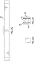
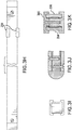
- a generic bar 300 Details of a generic bar 300 are shown in Figs. 3A -3K . Unless otherwise noted, all the bars discussed here have the same configuration. In this Figure, bar 300 is shown as being straight however, it can be circular ellipsoid or can have other geometric shape.
- the bar 300 includes two identical longitudinal segments 352, 354 facing each other. A cross- sectional view of segment 354 is seen in Fig. 3B .
- Segment 354 is formed of a C-shaped main body 355 made of a non-conductive material, such as a plastic material that is light weight but strong so that it can support various pendants, other bars, etc.
- a rail 356 is formed of a light weight conductive material such as aluminum.
- Preferably rail 356 is formed with a rectangular channel 360.
- the two segments 352, 354 are joined together at the two ends by end connectors 362.
- the connectors 362 are attached to the bars by conventional means, such as screws 364, by an adhesive or other means.
- the two segments 352, 354 have inner surfaces spaced at a nominal distance d throughout the length of the bar 300.
- the bar 300 is made in standard lengths ranging from to 12 to 48 inches.
- a spacer 366 is placed between the segments. The spacer 366 may be held in place by screws or other means.
- hangers for supporting bars from canopies There are several different types of bar hangers are provided: hangers for supporting bars from canopies, hangers for supporting bars from ceilings (without a power connection), hangers for supporting one bar from another bar and hangers for supporting pendants. All these hangers have must be able to interface with a bar at least at one end as described below.
- bar-to-bar hangers There are two types bar-to-bar hangers: parallel hangers for connecting two parallel bars and perpendicular hangers connecting two bars running perpendicular two each other.
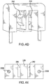
- Figs. 4A-4G show details of parallel bar hanger such as hanger 206 supporting bar 304 from bar 302 in Fig. 1 .
- the hanger 206 includes two vertical segments 230A, 230B. At the top and the bottom, the two segments 230A, 230B have their ends imbedded in identical W-shaped bases 232, shown in more detail in Figs. 9B-9E.
- the base 232 forms two channels 234, 236 with a wall 238 separating the two channels.
- the base 232 is further formed with two metallic springs or clips 240, 242. Clip 240 is electrically attached to segment 230A within the base 232, and clip 242 is connected to segment 230B.
- base 232 is made of a non-conductive material and is overmolded to cover portions of the clips 240, 242 and segments 230A, 230B.
- the two bases 232 have a single, unitary structure.
- at least the top base is made of two sections 232A, 232B that snap together along line 232 forming an interference fit therebetween.
- the bases 232 as sized and shaped so that they fit over and engage the bars 302, 304.
- the clips 240, 242 are sized and shaped so that they engage the rails 356, 358.
- the clips 240, 242 have a flat section 244 sized and shaped to snap into the channels 356, 358 of the bars 302, 304. In this manner not only do the clips 240, 242 provide a solid electrical contact with the rails 356, 358 but they also stabilize the hangers on the bars and insure that the lower bar 304 remains stiff and does move around in use.
- the clips may be made from beryllium copper.
- Hanger 208 has a similar configuration however the clips need not be connected electrically to the hanger segments. In other cases, for example, in the configuration shown in Fig. 2 , hangers 222 do provide electrical connection to bars 304A and 306A.
- the hanger segments 230A, 230B are provided in various lengths as required to obtain the various systems described above, and they are preferably made in the shape of rods of a stiff but somewhat springy material having shape memory such as a phosphor/bronze alloy. Preferably except where an electrical contact is required, the rods are covered or painted with a thin electrically insulating material.
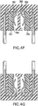
- the hangers can be installed by separating the two segments 230A, 230B, passing the ends of the respective bars 302, 304 between the segments, then lowering or raising the bars toward the respective bases 232 and then snapping the bases onto the bars into the configurations shown in Figs. 4F and 4G .
- the power bars extend perpendicularly to each other.
- bars 302 and 304 are perpendicular to each other.
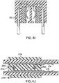
- These bars are interconnected using a hanger 222 shown in Figs. 4H-4J .
- This hanger 222 has two segments 272A, 272B and a base 232 similar to the base 232 in Figs. 9A-9G.
- at the bottom hanger 222 is provided with a different base 274.
- This base 274 is formed with two side wings 274A, 274B and a center wall 274C.
- Clips 276, 278 are provided on the center wall 274C and are connected electrically with segments 272A, 272B, respectively as show in Fig. 4J .
- the center wall 274C is made with two holes 280A, 280B with the lower ends of segments 272A, 272B extending into the holes and being secured to the base 222.
- the base 270 is sized and shaped to engage and support the power bar segments 304A, 304B of a bar 304A with the segments 272A, 272B providing power to these power bar segments.
- the base 232 engages the segments of the bar 302 in the manner discussed above.
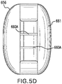
- Figs. 5A-5D show details of a pendant or light being laterally supported along its two sides by a pendant hanger 650.
- the pendant 650 includes a body 652 holding one or more LEDs or other types of light sources 654 ( Fig. 6H ).
- the light sources 654 are disposed behind a transparent or translucent lens or diffuser 656 ( Fig. 6F ).
- the back 661 of the light 650 can be blank or the light 650 can be provided with a second set of light sources similar to sources 654 covered by their own lens or diffuser.
- Body 652 is formed with two wings 658, 660, each formed with a longitudinal cavity 662, 664.
- the cavities 662, 664 have cross-sectional dimensions equal to or slightly smaller than rods 240, 242 and the wings 656, 660 are made of a material that is resilient so that the body 652 is snapped onto the rods 240, 242 with the wings 658, 550 forming an interference fit with the respective rods 240, 242.
- each wing 658, 660 is formed with one or more transversal or horizontal cutouts 658A, 660A. These cutouts are used to house horizontal knives 666. Knives 666 are made of a metallic material, such as steel or copper and are arranged so that the pendant 650 is snapped on the rods 240, 242, the knives 666 make a strong contact with the conducting portions of the rods 240, 242, thereby providing energy to the light sources 654.
- Figs. 6A-6H show details of a pendant 650 that is mounted between and supported by two rods 240, 242 of a hanger 200.
- the rods 240, 242 extend downwardly from base 244.
- the wings 658, 660 are shaped to enable the pendant 650 to be installed in two steps as illustrated in Figs. 6D and 6E .
- the pendant 650 is pushed forward until a first detent formed by curved surfaces 663 on the inner sidewalls of each wing 658, 660 grabs the respective rod 240, 242.
- the pendant 650 is pushed further in the direction B.
- the rods 240, 242 are covered with a thin layer of an insulating material or paint (not shown). As the pendant 650 is pushed in further to the position shown in Fig.
- Knives 666 are connected to internal wiring 667 that connects to a printed circuit board 665 providing power to the light sources 654 (See Figs. 5C and 6H ).
- Fig. 6B when the light 650 is fully mounted on the rods 240, 242 (in Fig. 5C rod 240 has been omitted for the sake of clarity), the knives 666 cut or pierce the insulation or coating 242A on rod 242 until they make mechanical and electrical contact with the core 242B of rod 242.
- the cores of the rods 240, 242 are connected to power sources and current from the rods are provided through wires 667 to the circuit board 665 and light sources 654.
- Fig. 6F shows details of the cover 656 and Figs. 6G and 6H show the details of the pendant 650 with and without the cover 656.
- cover 656 (and optionally back 661) can be made of a transparent or translucent material to act as a lens or diffuser for the light generated by sources 654.
- one or more lights 650 are incorporated or mounted on a modular light system, such as the ones shown in Figs. 1 and 2 .
- the hangers 200 used to support the lights 650 can be used to support other pendants as well, or even other power bars 300.
- the rods 240, 242 can be made of any desired lengths and that one or more lights 650 can be disposed on the rods 240, 242 at any distance from the base 242.
- rods 240, 242 are being shown as being disposed vertically, they could of course be disposed at an angle with respect to a vertical plane, or they could even be disposed horizontally.
- an end cap 246 may be provided to terminate the ends of the rods 240, 242, to hold them at a predetermined spacing and to protect them.
- End cap 246 is preferably made of a non-conducting material.
Landscapes
- Engineering & Computer Science (AREA)
- General Engineering & Computer Science (AREA)
- Power Engineering (AREA)
- Non-Portable Lighting Devices Or Systems Thereof (AREA)
- Fastening Of Light Sources Or Lamp Holders (AREA)
Applications Claiming Priority (2)
| Application Number | Priority Date | Filing Date | Title |
|---|---|---|---|
| US201662419505P | 2016-11-09 | 2016-11-09 | |
| US15/427,217 US10151466B2 (en) | 2016-11-09 | 2017-02-08 | Laterally supported lights |
Publications (2)
| Publication Number | Publication Date |
|---|---|
| EP3321568A1 true EP3321568A1 (de) | 2018-05-16 |
| EP3321568B1 EP3321568B1 (de) | 2020-02-05 |
Family
ID=60293795
Family Applications (1)
| Application Number | Title | Priority Date | Filing Date |
|---|---|---|---|
| EP17200541.5A Active EP3321568B1 (de) | 2016-11-09 | 2017-11-08 | Seitlich gestützte leuchten |
Country Status (4)
| Country | Link |
|---|---|
| US (1) | US10151466B2 (de) |
| EP (1) | EP3321568B1 (de) |
| CA (1) | CA2984651C (de) |
| ES (1) | ES2784958T3 (de) |
Cited By (1)
| Publication number | Priority date | Publication date | Assignee | Title |
|---|---|---|---|---|
| WO2022106108A1 (fr) * | 2020-11-23 | 2022-05-27 | Airstar Sas | Dispositif d'eclairage |
Families Citing this family (1)
| Publication number | Priority date | Publication date | Assignee | Title |
|---|---|---|---|---|
| US10665997B1 (en) * | 2019-01-04 | 2020-05-26 | Ptc International, Inc. | Adaptor for ornamental light emitting device and candolier including the same |
Citations (6)
| Publication number | Priority date | Publication date | Assignee | Title |
|---|---|---|---|---|
| US3748463A (en) * | 1972-08-30 | 1973-07-24 | Sormani Spa | Floor lamp |
| DE8708815U1 (de) * | 1987-06-25 | 1987-11-05 | Mawa Design Martin Wallroth GmbH, 1000 Berlin | Halogenbogenleuchte |
| US4758935A (en) * | 1985-07-24 | 1988-07-19 | S.A.M.E.S. S.P.A. | Ambient illumination system |
| DE29705852U1 (de) * | 1997-04-02 | 1997-05-15 | Chen, Meiric, Hsinchuan, Taipeh | Beleuchtungseinrichtung |
| DE202004001178U1 (de) * | 2004-01-27 | 2004-05-13 | Wisam Enterprises Co., Ltd. | Stehlampe, insbesondere mit verschiebbaren Lampenschirmen zur Installierung einer beliebigen Anzahl von Glühbirnen |
| US20100271834A1 (en) * | 2009-04-23 | 2010-10-28 | Future Tec (Hong Kong) Limited | Led lighting system |
Family Cites Families (109)
| Publication number | Priority date | Publication date | Assignee | Title |
|---|---|---|---|---|
| DE1414046U (de) | ||||
| FR608016A (fr) | 1925-12-16 | 1926-07-13 | Dispositif pour la concentration des flux lumineux émanant de sources différentes sur une même surface | |
| US2292395A (en) | 1940-02-06 | 1942-08-11 | Pierce John B Foundation | Composite electricity conductor unit |
| US3716031A (en) | 1971-02-26 | 1973-02-13 | Rowburg D | Quick release lariat honda |
| FR2588713A1 (fr) | 1985-10-16 | 1987-04-17 | Foucault Gerard | Dispositif pour l'alimentation et la fixation instantanee de sources tres basse-tension |
| USD301304S (en) | 1986-03-13 | 1989-05-30 | Lutron Electronics Co., Inc. | Mounting clip for releasably retaining an electric lamp control unit or similar article |
| US4723747A (en) | 1986-10-24 | 1988-02-09 | Capri Lighting | Bar hangers for recessed lighting fixtures |
| US4763870A (en) | 1987-02-11 | 1988-08-16 | Fortran Traffic Systems Limited | Traffic signal head |
| DE3742206A1 (de) | 1987-12-12 | 1989-06-22 | Josef Soelken Gmbh & Co Kg | Installationsteil fuer leuchten tragende niederspannungs-stromschienen |
| NL8900135A (nl) | 1989-01-20 | 1990-08-16 | Janse Lichtreklame Bv | Verlichtingssysteem voor reklamedoeleinden. |
| USD317058S (en) | 1989-08-14 | 1991-05-21 | Sonneman Design Group, Inc. | Wall mounted lamp assembly |
| USD320465S (en) | 1989-08-14 | 1991-10-01 | Sonneman Design Group Inc. | Hanging lamp assembly |
| US5025355A (en) | 1989-11-03 | 1991-06-18 | Harwood Ronald P | Combination lighting fixture and graphic display means |
| US5105349A (en) | 1990-09-24 | 1992-04-14 | Falls John W | Motorized chandelier lift system |
| FR2685947A1 (fr) | 1992-01-06 | 1993-07-09 | Applic Tech Decoratives Ec | Dispositif de support et d'alimentation pour un eclairage a tres basse tension. |
| US5440469A (en) | 1994-04-08 | 1995-08-08 | Gomes; Roy | Low voltage track lighting fixture |
| USD360046S (en) | 1994-07-01 | 1995-07-04 | Yazaki Industrial Chemical Co., Ltd. | Clamp-on holder for LED lamp |
| DE19510507C2 (de) | 1995-03-23 | 1999-11-18 | Alulite Lichtsysteme Gmbh | Elektrisches Leuchtensystem |
| USD392407S (en) | 1995-08-30 | 1998-03-17 | Phoenix Products Company, Inc. | Light fixture |
| US5833358A (en) | 1995-11-21 | 1998-11-10 | Aci The Display People | Extruded track lighting system |
| US5584576A (en) | 1995-11-27 | 1996-12-17 | Wei Hong; Shen | Clamping and connecting structure for track lights |
| DE19849101A1 (de) | 1997-10-24 | 1999-04-29 | Guenter Loof | Stromschienensystem |
| US6179442B1 (en) | 1998-09-21 | 2001-01-30 | S & S Stars, Llc | Christmas star light device |
| US6241369B1 (en) | 1998-11-20 | 2001-06-05 | Cooper Technologies Company | Quick mount fixture |
| US6135615A (en) | 1999-04-28 | 2000-10-24 | Lee; Cheng-Ping | Lamp suspension track assembly |
| US6244733B1 (en) | 2000-02-25 | 2001-06-12 | Juno Manufacturing, Inc. | Low voltage track lighting system |
| GB2361988B (en) | 2000-05-05 | 2004-03-03 | Avimo Ltd | Illumination system |
| US6489748B1 (en) | 2000-12-01 | 2002-12-03 | Cisco Technology, Inc. | Split backplane power system |
| US6341979B1 (en) | 2001-01-04 | 2002-01-29 | Monster Cable Products, Inc. | Electrical connector |
| US6769790B2 (en) | 2001-04-12 | 2004-08-03 | Fruehm Hermann | Theatrical lighting system with moving lights |
| US6676281B2 (en) | 2001-05-23 | 2004-01-13 | Sea Gull Lighting Products, Inc. | Rail lighting system |
| US6409524B1 (en) | 2001-07-30 | 2002-06-25 | Jack V. Miller | Side-mounted tracklight system |
| US6716042B2 (en) | 2002-07-05 | 2004-04-06 | Michael Lin | Track system of projector lamp and electrical connection device assembly thereof |
| US7172332B2 (en) | 2003-02-14 | 2007-02-06 | Tech Lighting L.L.C. | Field bendable line voltage track lighting system |
| USD507374S1 (en) | 2004-03-05 | 2005-07-12 | Tseng Mei Enterprise Co., Ltd. | Light |
| CA2461247A1 (en) | 2004-03-18 | 2005-09-18 | Simon-Victor Benghozi | Track lighting system |
| FR2869975B1 (fr) | 2004-05-04 | 2006-06-16 | Schneider Electric Ind Sas | Colonne de signalisation verrouillable |
| US20080190043A1 (en) | 2004-08-31 | 2008-08-14 | Waltraud Beckmann | Space Division System with Material Support Linkage |
| US7397384B1 (en) | 2005-02-11 | 2008-07-08 | Genlyte Thomas Group, Llc | Track lighting system current limiting device |
| EP1710772B1 (de) | 2005-04-06 | 2011-06-15 | Hemsson B.V. | Anordnung eines Mastes und Abrichtvorrichtung, Abrichtvorrichtung für eine derartige Anordnung und Verfahren zum Abrichten eines Mastes |
| US7661229B2 (en) | 2005-05-12 | 2010-02-16 | Worthington Armstrong Venture | Electrical conductivity in a suspended ceiling system |
| US8061865B2 (en) | 2005-05-23 | 2011-11-22 | Philips Solid-State Lighting Solutions, Inc. | Methods and apparatus for providing lighting via a grid system of a suspended ceiling |
| KR20060131248A (ko) | 2005-06-15 | 2006-12-20 | 삼성전자주식회사 | 백라이트 어셈블리 및 이를 갖는 액정표시장치 |
| ITMI20050301U1 (it) | 2005-08-26 | 2007-02-27 | Sarno Spa | Dispositivo di illuminazione con partalampada modulare e mobile per espositori e-o spazi di esposizione |
| US7364346B2 (en) | 2005-09-06 | 2008-04-29 | The L.D. Kichler Co. | Low voltage track lighting assembly and system |
| US7503778B2 (en) | 2005-12-30 | 2009-03-17 | Cooper Technologies Company | Lighting system and method |
| US7520762B2 (en) | 2005-12-30 | 2009-04-21 | Cooper Technologies Company | Lighting system and method |
| DE102006019194A1 (de) | 2006-04-21 | 2007-10-25 | Semperlux Ag - Lichttechnische Werke - | Mehrseitige Beleuchtungsanordnung mit Entblendung |
| US8616871B2 (en) | 2006-08-01 | 2013-12-31 | Galomb, Inc. | Hand operated injection molding apparatus |
| US7806913B2 (en) | 2006-08-16 | 2010-10-05 | Depuy Spine, Inc. | Modular multi-level spine stabilization system and method |
| CN200986123Y (zh) | 2006-12-06 | 2007-12-05 | 区炳文 | 磁接式低压灯具 |
| US7507005B1 (en) | 2007-01-30 | 2009-03-24 | Genlyte Thomas Group Llc | Sliding flexible track lighting |
| US7520763B1 (en) | 2007-06-29 | 2009-04-21 | Genlyte Thomas Group Llc | Track lighting system with dependent lamp cord |
| KR100904633B1 (ko) | 2007-08-21 | 2009-06-25 | 주식회사 필룩스 | 형광램프장치 |
| US7654834B1 (en) | 2008-05-05 | 2010-02-02 | Genlyte Thomas Group, Llc | Track lighting assembly |
| USD632423S1 (en) | 2008-05-14 | 2011-02-08 | Total Precision Cabinetry, Inc. | Modular bulkhead |
| US7571736B1 (en) | 2008-08-22 | 2009-08-11 | Wai Chuen Chu | Illuminated umbrella |
| US7798824B2 (en) | 2008-08-28 | 2010-09-21 | Juno Manufacturing, Inc. | Adapter for line voltage track |
| USD595884S1 (en) | 2008-12-30 | 2009-07-07 | S-Sun Enterprise Co., Ltd | Bicycle light |
| USD611169S1 (en) | 2009-02-09 | 2010-03-02 | Harder Willard J | Deck rail |
| USD617034S1 (en) | 2009-08-12 | 2010-06-01 | U.S. Pole Company, Inc. | Lighting fixture |
| WO2011056782A1 (en) | 2009-11-04 | 2011-05-12 | Hogue Surgical, Llc | Adjustable optical fiber connector |
| US9136659B2 (en) | 2009-12-15 | 2015-09-15 | Koninklijke Philips N.V. | Downward compatible voltage track lighting system |
| USD620168S1 (en) | 2010-01-04 | 2010-07-20 | Eglo Leuchten Gmbh | Light fixture |
| US8523378B2 (en) | 2010-03-01 | 2013-09-03 | Minka Lighting, Inc. | Combination ceiling fan and track light |
| US8398276B2 (en) | 2010-03-12 | 2013-03-19 | Tempo Industries, Llc | Wall mounted aisle, step and corridor light system |
| US8733710B1 (en) | 2010-04-13 | 2014-05-27 | Marken Global, LLC | Clamp display system |
| US9387268B2 (en) | 2010-06-01 | 2016-07-12 | Alexander Farren | Compositions and methods for UV sterilization |
| US7955125B1 (en) | 2010-10-14 | 2011-06-07 | Souriau Usa, Inc. | Electrical connector with one end threadably connected to a junction box and other end configured to be connected to a mating electrical connector |
| USD648470S1 (en) | 2010-12-01 | 2011-11-08 | Light Muse, LLC | Light pod |
| USD649692S1 (en) | 2011-01-04 | 2011-11-29 | LEDs ON | Extrusion for LED-based lighting apparatus |
| US8714775B2 (en) | 2011-04-11 | 2014-05-06 | Swarovski Lighting, Ltd. | Light fixtures, methods of suspending a plurality of light sources, an ornament mounting, and a method for mounting an ornament |
| US8794804B2 (en) | 2011-10-18 | 2014-08-05 | Orion Energy Systems, Inc. | System and method for supporting and leveling a light fixture |
| EP2615700B1 (de) | 2012-01-11 | 2015-03-11 | OSRAM GmbH | Beleuchtungsmodul |
| US9673582B2 (en) | 2012-01-17 | 2017-06-06 | Joseph Guilmette | Modular housing and track assemblies for tubular lamps |
| USD680673S1 (en) | 2012-03-19 | 2013-04-23 | Jonathan E. Levine | Lighting device |
| USD671670S1 (en) | 2012-04-09 | 2012-11-27 | Sonneman Robert A | Light fixture with multiple supports |
| US9360196B2 (en) | 2012-06-15 | 2016-06-07 | Rtc Industries, Inc. | Low voltage power supply for a merchandise display system |
| USD689221S1 (en) | 2012-07-23 | 2013-09-03 | Rafi Isaac | Waterproof lamp |
| WO2014081842A1 (en) | 2012-11-20 | 2014-05-30 | Molex Incorporated | Lamp fixture and led module for same |
| DE102013100435A1 (de) | 2013-01-16 | 2014-07-17 | Conductix-Wampfler Gmbh | Verbindungselement für eine Schleifleitung, Schleifleitung und Verfahren zur Herstellung einer Schleifleitung |
| CN105026826B (zh) | 2013-03-07 | 2018-02-23 | 飞利浦灯具控股公司 | 照明系统、用于其的轨道和照明模块 |
| US8967573B2 (en) | 2013-03-14 | 2015-03-03 | Dental Equipment, Llc | Modular, bypass track and carriage system for overhead-mounted lights and other devices |
| CA150672S (en) | 2013-04-09 | 2014-06-12 | Peter Joseph Maher | Stick holder |
| USD739070S1 (en) | 2013-04-15 | 2015-09-15 | Artemide S.P.A. | Table lamp |
| NL2011072C2 (nl) | 2013-07-01 | 2015-01-06 | Flowmagic Holding B V | Samenstel van spanningsrail, adapter en led-tube, adapter kennelijk geschikt voor het gebruikmaken van het samenstel en werkwijze voor het aanbrengen van verlichtingselementen. |
| CA2859584A1 (en) | 2013-08-15 | 2015-02-15 | Evolution Lighting Llc | Interchangeable lighting fixtures for track and wall lighting system |
| US9464772B2 (en) | 2014-01-13 | 2016-10-11 | Cordelia Lighting Inc. | Ambient directional combination light fixture |
| CN105299524B (zh) | 2014-05-26 | 2018-06-05 | 赛尔富电子有限公司 | 一种led条形轨道灯 |
| WO2016132361A1 (en) | 2015-02-17 | 2016-08-25 | Chocolate Lighting Company Ltd | Track lighting system |
| WO2016150564A2 (en) | 2015-03-20 | 2016-09-29 | Hesalight A/S | Modular magnetic track lighting system |
| USD765296S1 (en) | 2015-05-04 | 2016-08-30 | Ningbo Loyal Lighting Technology Co., Ltd. | Light fixture |
| CN205261379U (zh) | 2015-12-03 | 2016-05-25 | 江门市普锐高科照明有限公司 | 多角度防眩光自然对流轨道灯 |
| EP3470733B1 (de) | 2016-01-07 | 2019-12-18 | Contemporary Visions, LLC | Modulares beleuchtungssystem unter verwendung von hängeelementen und stromleisten |
| US9879845B2 (en) | 2016-01-07 | 2018-01-30 | Robert A. Sonneman | Modular lighting system using hangers and power bars |
| USD773101S1 (en) | 2016-01-11 | 2016-11-29 | Robert A. Sonneman | Lighting fixture |
| USD772467S1 (en) | 2016-01-08 | 2016-11-22 | Robert A. Sonneman | Light fixture |
| USD773099S1 (en) | 2016-01-12 | 2016-11-29 | Robert A. Sonneman | Circular lighting fixture |
| USD773725S1 (en) | 2016-05-13 | 2016-12-06 | Robert A. Sonneman | Canopy for light fixtures with multiple supports |
| USD773719S1 (en) | 2016-05-25 | 2016-12-06 | Robert A. Sonneman | Lighting system |
| USD775397S1 (en) | 2016-05-27 | 2016-12-27 | Robert A. Sonneman | Lighting fixture |
| USD779713S1 (en) | 2016-06-30 | 2017-02-21 | Robert A. Sonneman | Insulated hanger for a lighting system |
| USD779712S1 (en) | 2016-06-30 | 2017-02-21 | Robert A. Sonneman | W-shaped bar connector for a lighting system |
| USD779714S1 (en) | 2016-06-30 | 2017-02-21 | Robert A. Sonneman | Insulated hanger with a cover for a lighting system |
| USD772475S1 (en) | 2016-07-05 | 2016-11-22 | Robert A. Sonneman | Single bar hanger for a lighting system |
| USD779715S1 (en) | 2016-08-26 | 2017-02-21 | Robert A. Sonneman | Right angle power bar suspender for a lighting system |
| USD779113S1 (en) | 2016-08-26 | 2017-02-14 | Robert A. Sonneman | Parallel power bar suspender for a lighting system |
| USD779437S1 (en) | 2016-08-31 | 2017-02-21 | Robert A. Sonneman | Power rod connector for a lighting system |
| USD782990S1 (en) | 2016-09-07 | 2017-04-04 | Robert A. Sonneman | Power box for a lighting system |
-
2017
- 2017-02-08 US US15/427,217 patent/US10151466B2/en active Active
- 2017-11-02 CA CA2984651A patent/CA2984651C/en not_active Expired - Fee Related
- 2017-11-08 ES ES17200541T patent/ES2784958T3/es active Active
- 2017-11-08 EP EP17200541.5A patent/EP3321568B1/de active Active
Patent Citations (6)
| Publication number | Priority date | Publication date | Assignee | Title |
|---|---|---|---|---|
| US3748463A (en) * | 1972-08-30 | 1973-07-24 | Sormani Spa | Floor lamp |
| US4758935A (en) * | 1985-07-24 | 1988-07-19 | S.A.M.E.S. S.P.A. | Ambient illumination system |
| DE8708815U1 (de) * | 1987-06-25 | 1987-11-05 | Mawa Design Martin Wallroth GmbH, 1000 Berlin | Halogenbogenleuchte |
| DE29705852U1 (de) * | 1997-04-02 | 1997-05-15 | Chen, Meiric, Hsinchuan, Taipeh | Beleuchtungseinrichtung |
| DE202004001178U1 (de) * | 2004-01-27 | 2004-05-13 | Wisam Enterprises Co., Ltd. | Stehlampe, insbesondere mit verschiebbaren Lampenschirmen zur Installierung einer beliebigen Anzahl von Glühbirnen |
| US20100271834A1 (en) * | 2009-04-23 | 2010-10-28 | Future Tec (Hong Kong) Limited | Led lighting system |
Cited By (2)
| Publication number | Priority date | Publication date | Assignee | Title |
|---|---|---|---|---|
| WO2022106108A1 (fr) * | 2020-11-23 | 2022-05-27 | Airstar Sas | Dispositif d'eclairage |
| FR3116589A1 (fr) * | 2020-11-23 | 2022-05-27 | Airstar Sas | Dispositif d'éclairage |
Also Published As
| Publication number | Publication date |
|---|---|
| CA2984651A1 (en) | 2018-05-09 |
| US20180128465A1 (en) | 2018-05-10 |
| EP3321568B1 (de) | 2020-02-05 |
| CA2984651C (en) | 2020-03-10 |
| US10151466B2 (en) | 2018-12-11 |
| ES2784958T3 (es) | 2020-10-02 |
Similar Documents
| Publication | Publication Date | Title |
|---|---|---|
| US10288271B2 (en) | Canopy for a modular lighting system | |
| CA2984652C (en) | Power bar hanger for modular lighting system | |
| EP3470733B1 (de) | Modulares beleuchtungssystem unter verwendung von hängeelementen und stromleisten | |
| EP3321569A1 (de) | Niederprofilaufhängevorrichtung für modulares beleuchtungssystem | |
| US20180128460A1 (en) | Cylindrical housing for modular lighting system | |
| EP3321563A1 (de) | Leuchtstab für ein beleuchtungssystem | |
| CA2984651C (en) | Laterally supported lights | |
| CA2954263C (en) | Modular lighting system using hangers and power bars |
Legal Events
| Date | Code | Title | Description |
|---|---|---|---|
| PUAI | Public reference made under article 153(3) epc to a published international application that has entered the european phase |
Free format text: ORIGINAL CODE: 0009012 |
|
| STAA | Information on the status of an ep patent application or granted ep patent |
Free format text: STATUS: THE APPLICATION HAS BEEN PUBLISHED |
|
| AK | Designated contracting states |
Kind code of ref document: A1 Designated state(s): AL AT BE BG CH CY CZ DE DK EE ES FI FR GB GR HR HU IE IS IT LI LT LU LV MC MK MT NL NO PL PT RO RS SE SI SK SM TR |
|
| AX | Request for extension of the european patent |
Extension state: BA ME |
|
| RAP1 | Party data changed (applicant data changed or rights of an application transferred) |
Owner name: CONTEMPORARY VISIONS, LLC |
|
| RIN1 | Information on inventor provided before grant (corrected) |
Inventor name: SONNEMAN, ROBERT, A. |
|
| STAA | Information on the status of an ep patent application or granted ep patent |
Free format text: STATUS: REQUEST FOR EXAMINATION WAS MADE |
|
| 17P | Request for examination filed |
Effective date: 20181026 |
|
| RBV | Designated contracting states (corrected) |
Designated state(s): AL AT BE BG CH CY CZ DE DK EE ES FI FR GB GR HR HU IE IS IT LI LT LU LV MC MK MT NL NO PL PT RO RS SE SI SK SM TR |
|
| STAA | Information on the status of an ep patent application or granted ep patent |
Free format text: STATUS: EXAMINATION IS IN PROGRESS |
|
| 17Q | First examination report despatched |
Effective date: 20181218 |
|
| RIC1 | Information provided on ipc code assigned before grant |
Ipc: F21Y 115/10 20160101ALN20190708BHEP Ipc: F21V 21/08 20060101ALI20190708BHEP Ipc: F21V 21/104 20060101ALI20190708BHEP Ipc: F21V 21/35 20060101ALI20190708BHEP Ipc: F21Y 105/10 20160101ALN20190708BHEP Ipc: F21V 21/002 20060101ALN20190708BHEP Ipc: F21S 8/06 20060101AFI20190708BHEP |
|
| GRAP | Despatch of communication of intention to grant a patent |
Free format text: ORIGINAL CODE: EPIDOSNIGR1 |
|
| STAA | Information on the status of an ep patent application or granted ep patent |
Free format text: STATUS: GRANT OF PATENT IS INTENDED |
|
| INTG | Intention to grant announced |
Effective date: 20190823 |
|
| GRAS | Grant fee paid |
Free format text: ORIGINAL CODE: EPIDOSNIGR3 |
|
| GRAA | (expected) grant |
Free format text: ORIGINAL CODE: 0009210 |
|
| STAA | Information on the status of an ep patent application or granted ep patent |
Free format text: STATUS: THE PATENT HAS BEEN GRANTED |
|
| AK | Designated contracting states |
Kind code of ref document: B1 Designated state(s): AL AT BE BG CH CY CZ DE DK EE ES FI FR GB GR HR HU IE IS IT LI LT LU LV MC MK MT NL NO PL PT RO RS SE SI SK SM TR |
|
| REG | Reference to a national code |
Ref country code: GB Ref legal event code: FG4D |
|
| REG | Reference to a national code |
Ref country code: AT Ref legal event code: REF Ref document number: 1230168 Country of ref document: AT Kind code of ref document: T Effective date: 20200215 |
|
| REG | Reference to a national code |
Ref country code: DE Ref legal event code: R096 Ref document number: 602017011347 Country of ref document: DE |
|
| REG | Reference to a national code |
Ref country code: IE Ref legal event code: FG4D |
|
| REG | Reference to a national code |
Ref country code: CH Ref legal event code: EP |
|
| REG | Reference to a national code |
Ref country code: NL Ref legal event code: MP Effective date: 20200205 |
|
| PG25 | Lapsed in a contracting state [announced via postgrant information from national office to epo] |
Ref country code: RS Free format text: LAPSE BECAUSE OF FAILURE TO SUBMIT A TRANSLATION OF THE DESCRIPTION OR TO PAY THE FEE WITHIN THE PRESCRIBED TIME-LIMIT Effective date: 20200205 Ref country code: FI Free format text: LAPSE BECAUSE OF FAILURE TO SUBMIT A TRANSLATION OF THE DESCRIPTION OR TO PAY THE FEE WITHIN THE PRESCRIBED TIME-LIMIT Effective date: 20200205 Ref country code: PT Free format text: LAPSE BECAUSE OF FAILURE TO SUBMIT A TRANSLATION OF THE DESCRIPTION OR TO PAY THE FEE WITHIN THE PRESCRIBED TIME-LIMIT Effective date: 20200628 Ref country code: NO Free format text: LAPSE BECAUSE OF FAILURE TO SUBMIT A TRANSLATION OF THE DESCRIPTION OR TO PAY THE FEE WITHIN THE PRESCRIBED TIME-LIMIT Effective date: 20200505 |
|
| REG | Reference to a national code |
Ref country code: LT Ref legal event code: MG4D |
|
| PG25 | Lapsed in a contracting state [announced via postgrant information from national office to epo] |
Ref country code: LV Free format text: LAPSE BECAUSE OF FAILURE TO SUBMIT A TRANSLATION OF THE DESCRIPTION OR TO PAY THE FEE WITHIN THE PRESCRIBED TIME-LIMIT Effective date: 20200205 Ref country code: SE Free format text: LAPSE BECAUSE OF FAILURE TO SUBMIT A TRANSLATION OF THE DESCRIPTION OR TO PAY THE FEE WITHIN THE PRESCRIBED TIME-LIMIT Effective date: 20200205 Ref country code: IS Free format text: LAPSE BECAUSE OF FAILURE TO SUBMIT A TRANSLATION OF THE DESCRIPTION OR TO PAY THE FEE WITHIN THE PRESCRIBED TIME-LIMIT Effective date: 20200605 Ref country code: GR Free format text: LAPSE BECAUSE OF FAILURE TO SUBMIT A TRANSLATION OF THE DESCRIPTION OR TO PAY THE FEE WITHIN THE PRESCRIBED TIME-LIMIT Effective date: 20200506 Ref country code: BG Free format text: LAPSE BECAUSE OF FAILURE TO SUBMIT A TRANSLATION OF THE DESCRIPTION OR TO PAY THE FEE WITHIN THE PRESCRIBED TIME-LIMIT Effective date: 20200505 Ref country code: HR Free format text: LAPSE BECAUSE OF FAILURE TO SUBMIT A TRANSLATION OF THE DESCRIPTION OR TO PAY THE FEE WITHIN THE PRESCRIBED TIME-LIMIT Effective date: 20200205 |
|
| PG25 | Lapsed in a contracting state [announced via postgrant information from national office to epo] |
Ref country code: NL Free format text: LAPSE BECAUSE OF FAILURE TO SUBMIT A TRANSLATION OF THE DESCRIPTION OR TO PAY THE FEE WITHIN THE PRESCRIBED TIME-LIMIT Effective date: 20200205 |
|
| REG | Reference to a national code |
Ref country code: ES Ref legal event code: FG2A Ref document number: 2784958 Country of ref document: ES Kind code of ref document: T3 Effective date: 20201002 |
|
| PG25 | Lapsed in a contracting state [announced via postgrant information from national office to epo] |
Ref country code: SM Free format text: LAPSE BECAUSE OF FAILURE TO SUBMIT A TRANSLATION OF THE DESCRIPTION OR TO PAY THE FEE WITHIN THE PRESCRIBED TIME-LIMIT Effective date: 20200205 Ref country code: LT Free format text: LAPSE BECAUSE OF FAILURE TO SUBMIT A TRANSLATION OF THE DESCRIPTION OR TO PAY THE FEE WITHIN THE PRESCRIBED TIME-LIMIT Effective date: 20200205 Ref country code: SK Free format text: LAPSE BECAUSE OF FAILURE TO SUBMIT A TRANSLATION OF THE DESCRIPTION OR TO PAY THE FEE WITHIN THE PRESCRIBED TIME-LIMIT Effective date: 20200205 Ref country code: DK Free format text: LAPSE BECAUSE OF FAILURE TO SUBMIT A TRANSLATION OF THE DESCRIPTION OR TO PAY THE FEE WITHIN THE PRESCRIBED TIME-LIMIT Effective date: 20200205 Ref country code: CZ Free format text: LAPSE BECAUSE OF FAILURE TO SUBMIT A TRANSLATION OF THE DESCRIPTION OR TO PAY THE FEE WITHIN THE PRESCRIBED TIME-LIMIT Effective date: 20200205 Ref country code: RO Free format text: LAPSE BECAUSE OF FAILURE TO SUBMIT A TRANSLATION OF THE DESCRIPTION OR TO PAY THE FEE WITHIN THE PRESCRIBED TIME-LIMIT Effective date: 20200205 Ref country code: EE Free format text: LAPSE BECAUSE OF FAILURE TO SUBMIT A TRANSLATION OF THE DESCRIPTION OR TO PAY THE FEE WITHIN THE PRESCRIBED TIME-LIMIT Effective date: 20200205 |
|
| REG | Reference to a national code |
Ref country code: DE Ref legal event code: R097 Ref document number: 602017011347 Country of ref document: DE |
|
| REG | Reference to a national code |
Ref country code: AT Ref legal event code: MK05 Ref document number: 1230168 Country of ref document: AT Kind code of ref document: T Effective date: 20200205 |
|
| PLBE | No opposition filed within time limit |
Free format text: ORIGINAL CODE: 0009261 |
|
| STAA | Information on the status of an ep patent application or granted ep patent |
Free format text: STATUS: NO OPPOSITION FILED WITHIN TIME LIMIT |
|
| 26N | No opposition filed |
Effective date: 20201106 |
|
| PG25 | Lapsed in a contracting state [announced via postgrant information from national office to epo] |
Ref country code: AT Free format text: LAPSE BECAUSE OF FAILURE TO SUBMIT A TRANSLATION OF THE DESCRIPTION OR TO PAY THE FEE WITHIN THE PRESCRIBED TIME-LIMIT Effective date: 20200205 |
|
| PG25 | Lapsed in a contracting state [announced via postgrant information from national office to epo] |
Ref country code: SI Free format text: LAPSE BECAUSE OF FAILURE TO SUBMIT A TRANSLATION OF THE DESCRIPTION OR TO PAY THE FEE WITHIN THE PRESCRIBED TIME-LIMIT Effective date: 20200205 Ref country code: PL Free format text: LAPSE BECAUSE OF FAILURE TO SUBMIT A TRANSLATION OF THE DESCRIPTION OR TO PAY THE FEE WITHIN THE PRESCRIBED TIME-LIMIT Effective date: 20200205 |
|
| PG25 | Lapsed in a contracting state [announced via postgrant information from national office to epo] |
Ref country code: MC Free format text: LAPSE BECAUSE OF FAILURE TO SUBMIT A TRANSLATION OF THE DESCRIPTION OR TO PAY THE FEE WITHIN THE PRESCRIBED TIME-LIMIT Effective date: 20200205 |
|
| REG | Reference to a national code |
Ref country code: CH Ref legal event code: PL |
|
| PG25 | Lapsed in a contracting state [announced via postgrant information from national office to epo] |
Ref country code: LU Free format text: LAPSE BECAUSE OF NON-PAYMENT OF DUE FEES Effective date: 20201108 |
|
| REG | Reference to a national code |
Ref country code: BE Ref legal event code: MM Effective date: 20201130 |
|
| PG25 | Lapsed in a contracting state [announced via postgrant information from national office to epo] |
Ref country code: CH Free format text: LAPSE BECAUSE OF NON-PAYMENT OF DUE FEES Effective date: 20201130 Ref country code: LI Free format text: LAPSE BECAUSE OF NON-PAYMENT OF DUE FEES Effective date: 20201130 |
|
| PG25 | Lapsed in a contracting state [announced via postgrant information from national office to epo] |
Ref country code: IE Free format text: LAPSE BECAUSE OF NON-PAYMENT OF DUE FEES Effective date: 20201108 Ref country code: FR Free format text: LAPSE BECAUSE OF NON-PAYMENT OF DUE FEES Effective date: 20201130 |
|
| PGFP | Annual fee paid to national office [announced via postgrant information from national office to epo] |
Ref country code: ES Payment date: 20211213 Year of fee payment: 5 Ref country code: DE Payment date: 20211129 Year of fee payment: 5 |
|
| PGFP | Annual fee paid to national office [announced via postgrant information from national office to epo] |
Ref country code: IT Payment date: 20211006 Year of fee payment: 5 |
|
| PG25 | Lapsed in a contracting state [announced via postgrant information from national office to epo] |
Ref country code: TR Free format text: LAPSE BECAUSE OF FAILURE TO SUBMIT A TRANSLATION OF THE DESCRIPTION OR TO PAY THE FEE WITHIN THE PRESCRIBED TIME-LIMIT Effective date: 20200205 Ref country code: MT Free format text: LAPSE BECAUSE OF FAILURE TO SUBMIT A TRANSLATION OF THE DESCRIPTION OR TO PAY THE FEE WITHIN THE PRESCRIBED TIME-LIMIT Effective date: 20200205 Ref country code: CY Free format text: LAPSE BECAUSE OF FAILURE TO SUBMIT A TRANSLATION OF THE DESCRIPTION OR TO PAY THE FEE WITHIN THE PRESCRIBED TIME-LIMIT Effective date: 20200205 |
|
| PG25 | Lapsed in a contracting state [announced via postgrant information from national office to epo] |
Ref country code: MK Free format text: LAPSE BECAUSE OF FAILURE TO SUBMIT A TRANSLATION OF THE DESCRIPTION OR TO PAY THE FEE WITHIN THE PRESCRIBED TIME-LIMIT Effective date: 20200205 Ref country code: AL Free format text: LAPSE BECAUSE OF FAILURE TO SUBMIT A TRANSLATION OF THE DESCRIPTION OR TO PAY THE FEE WITHIN THE PRESCRIBED TIME-LIMIT Effective date: 20200205 |
|
| GBPC | Gb: european patent ceased through non-payment of renewal fee |
Effective date: 20211108 |
|
| PG25 | Lapsed in a contracting state [announced via postgrant information from national office to epo] |
Ref country code: BE Free format text: LAPSE BECAUSE OF NON-PAYMENT OF DUE FEES Effective date: 20201130 |
|
| PG25 | Lapsed in a contracting state [announced via postgrant information from national office to epo] |
Ref country code: GB Free format text: LAPSE BECAUSE OF NON-PAYMENT OF DUE FEES Effective date: 20211108 |
|
| REG | Reference to a national code |
Ref country code: DE Ref legal event code: R119 Ref document number: 602017011347 Country of ref document: DE |
|
| PG25 | Lapsed in a contracting state [announced via postgrant information from national office to epo] |
Ref country code: IT Free format text: LAPSE BECAUSE OF NON-PAYMENT OF DUE FEES Effective date: 20221108 Ref country code: DE Free format text: LAPSE BECAUSE OF NON-PAYMENT OF DUE FEES Effective date: 20230601 |
|
| REG | Reference to a national code |
Ref country code: ES Ref legal event code: FD2A Effective date: 20231228 |
|
| PG25 | Lapsed in a contracting state [announced via postgrant information from national office to epo] |
Ref country code: ES Free format text: LAPSE BECAUSE OF NON-PAYMENT OF DUE FEES Effective date: 20221109 |
|
| PG25 | Lapsed in a contracting state [announced via postgrant information from national office to epo] |
Ref country code: ES Free format text: LAPSE BECAUSE OF NON-PAYMENT OF DUE FEES Effective date: 20221109 |