EP3321569A1 - Cintre à profil bas pour système d'éclairage modulaire - Google Patents
Cintre à profil bas pour système d'éclairage modulaire Download PDFInfo
- Publication number
- EP3321569A1 EP3321569A1 EP17200563.9A EP17200563A EP3321569A1 EP 3321569 A1 EP3321569 A1 EP 3321569A1 EP 17200563 A EP17200563 A EP 17200563A EP 3321569 A1 EP3321569 A1 EP 3321569A1
- Authority
- EP
- European Patent Office
- Prior art keywords
- hanger
- bar
- power
- base
- hangers
- Prior art date
- Legal status (The legal status is an assumption and is not a legal conclusion. Google has not performed a legal analysis and makes no representation as to the accuracy of the status listed.)
- Withdrawn
Links
Images




Classifications
-
- F—MECHANICAL ENGINEERING; LIGHTING; HEATING; WEAPONS; BLASTING
- F21—LIGHTING
- F21V—FUNCTIONAL FEATURES OR DETAILS OF LIGHTING DEVICES OR SYSTEMS THEREOF; STRUCTURAL COMBINATIONS OF LIGHTING DEVICES WITH OTHER ARTICLES, NOT OTHERWISE PROVIDED FOR
- F21V23/00—Arrangement of electric circuit elements in or on lighting devices
- F21V23/06—Arrangement of electric circuit elements in or on lighting devices the elements being coupling devices, e.g. connectors
-
- F—MECHANICAL ENGINEERING; LIGHTING; HEATING; WEAPONS; BLASTING
- F21—LIGHTING
- F21S—NON-PORTABLE LIGHTING DEVICES; SYSTEMS THEREOF; VEHICLE LIGHTING DEVICES SPECIALLY ADAPTED FOR VEHICLE EXTERIORS
- F21S8/00—Lighting devices intended for fixed installation
- F21S8/04—Lighting devices intended for fixed installation intended only for mounting on a ceiling or the like overhead structures
- F21S8/06—Lighting devices intended for fixed installation intended only for mounting on a ceiling or the like overhead structures by suspension
- F21S8/061—Lighting devices intended for fixed installation intended only for mounting on a ceiling or the like overhead structures by suspension with a non-rigid pendant, i.e. a cable, wire or chain
-
- F—MECHANICAL ENGINEERING; LIGHTING; HEATING; WEAPONS; BLASTING
- F21—LIGHTING
- F21S—NON-PORTABLE LIGHTING DEVICES; SYSTEMS THEREOF; VEHICLE LIGHTING DEVICES SPECIALLY ADAPTED FOR VEHICLE EXTERIORS
- F21S8/00—Lighting devices intended for fixed installation
- F21S8/04—Lighting devices intended for fixed installation intended only for mounting on a ceiling or the like overhead structures
- F21S8/06—Lighting devices intended for fixed installation intended only for mounting on a ceiling or the like overhead structures by suspension
- F21S8/063—Lighting devices intended for fixed installation intended only for mounting on a ceiling or the like overhead structures by suspension with a rigid pendant, i.e. a pipe or rod
-
- F—MECHANICAL ENGINEERING; LIGHTING; HEATING; WEAPONS; BLASTING
- F21—LIGHTING
- F21V—FUNCTIONAL FEATURES OR DETAILS OF LIGHTING DEVICES OR SYSTEMS THEREOF; STRUCTURAL COMBINATIONS OF LIGHTING DEVICES WITH OTHER ARTICLES, NOT OTHERWISE PROVIDED FOR
- F21V21/00—Supporting, suspending, or attaching arrangements for lighting devices; Hand grips
- F21V21/10—Pendants, arms, or standards; Fixing lighting devices to pendants, arms, or standards
- F21V21/108—Arms
-
- F—MECHANICAL ENGINEERING; LIGHTING; HEATING; WEAPONS; BLASTING
- F21—LIGHTING
- F21V—FUNCTIONAL FEATURES OR DETAILS OF LIGHTING DEVICES OR SYSTEMS THEREOF; STRUCTURAL COMBINATIONS OF LIGHTING DEVICES WITH OTHER ARTICLES, NOT OTHERWISE PROVIDED FOR
- F21V21/00—Supporting, suspending, or attaching arrangements for lighting devices; Hand grips
- F21V21/34—Supporting elements displaceable along a guiding element
- F21V21/35—Supporting elements displaceable along a guiding element with direct electrical contact between the supporting element and electric conductors running along the guiding element
-
- F—MECHANICAL ENGINEERING; LIGHTING; HEATING; WEAPONS; BLASTING
- F21—LIGHTING
- F21V—FUNCTIONAL FEATURES OR DETAILS OF LIGHTING DEVICES OR SYSTEMS THEREOF; STRUCTURAL COMBINATIONS OF LIGHTING DEVICES WITH OTHER ARTICLES, NOT OTHERWISE PROVIDED FOR
- F21V23/00—Arrangement of electric circuit elements in or on lighting devices
-
- H—ELECTRICITY
- H01—ELECTRIC ELEMENTS
- H01R—ELECTRICALLY-CONDUCTIVE CONNECTIONS; STRUCTURAL ASSOCIATIONS OF A PLURALITY OF MUTUALLY-INSULATED ELECTRICAL CONNECTING ELEMENTS; COUPLING DEVICES; CURRENT COLLECTORS
- H01R13/00—Details of coupling devices of the kinds covered by groups H01R12/70 or H01R24/00 - H01R33/00
- H01R13/62—Means for facilitating engagement or disengagement of coupling parts or for holding them in engagement
-
- H—ELECTRICITY
- H01—ELECTRIC ELEMENTS
- H01R—ELECTRICALLY-CONDUCTIVE CONNECTIONS; STRUCTURAL ASSOCIATIONS OF A PLURALITY OF MUTUALLY-INSULATED ELECTRICAL CONNECTING ELEMENTS; COUPLING DEVICES; CURRENT COLLECTORS
- H01R25/00—Coupling parts adapted for simultaneous co-operation with two or more identical counterparts, e.g. for distributing energy to two or more circuits
- H01R25/14—Rails or bus-bars constructed so that the counterparts can be connected thereto at any point along their length
Definitions
- This invention pertains to a connector interconnecting two power bars or connecting a pendant to a power bar in modular lighting systems.
- the connector includes a two-piece low profile body selectively attached to a power bar and either rods or a flexible cord extending from the body.
- ceiling lights Several different types are presently available, including surface mounted lights, recessed lights and hanging lights.
- the present invention pertains to hanging lights.
- a modular lighting system for providing light in a space includes canopies connectable to a power source; a plurality of horizontal bars; a plurality of hangers, including a first set of hangers supporting bars from said canopy and a second set of hangers, each said hangers including a first end disposed between and engaging said bar segment.
- the system further includes a plurality of pendants supported by the second set of hangers from the bars. The hangers and bars cooperate to provide electric power to said pendants from said canopy.
- each bar includes two bar segments facing each other and being made of a non-conductive material.
- Conductive rails are provided on the inner surface of each bar segment.
- the hangers include a base configured to form an interference fit with the bar segments.
- the hangers are made of conductive rods or cables that are in electrical contact with the rails through the respective bases.
- the bars are straight or linear. In another embodiment, the bars are circular or have some other curvilinear shape.
- the bars preferably extend horizontally, however, different bars are disposed at different heights and are supported from one or more canopies or straight from a ceiling by hangers of various configurations or cables.
- At least one of the canopies is connected to a line voltage and transformer is used to step down the line voltage to a lower voltage such as 24 vac which is then distributed to the pendants through the hangers and bars.
- the pendants include light emitting elements such as LEDs, electronic circuitry for driving the LEDs, and are preferably shaped for heat dissipation. Since the LEDs have a long life, they are not replaceable but instead the whole pendant is replaced as needed.
- One class of configuration may include several bars disposed in a vertical plane. In another class of configurations, several bars extend at different angles in one plane, and are joined at a common point. Another class of configurations may include a combination of the first to classes. Another class of configurations may include several bars disposed at different heights or tiers, some bars being perpendicular to other bars.
- a hanger for supporting a power bar of a lighting system wherein the power bar including two segments with respective rails arranged and constructed to deliver power to pendants.
- the hanger includes:
- a cover is positioned above said body, said body and cover being shaped and sized to snap together to form an interference fit and defining said base.
- a conductive member formed of a cord or a pair of spaced rods connects the hanger to a pendant or another power bar.
- Fig. 1 show the elements of modular lighting systems constructed in accordance with this invention.
- each system includes one or more canopies 100, a plurality of hangers 200, a plurality of power bars 300 and a plurality of pendants 400.
- some systems may also include optional connectors 500.
- system 10 includes a canopy 100 that supports the system from a ceiling or other similar architectural member in a conventional manner.
- the canopy 100 also provides power to the system.
- Other, more complicated systems may have several canopies provided for support and only some or only one canopy may also provide power.
- Canopy 100 includes a conventional power supply connected to standard AC lines for providing power to the LED tubes in the pendants as discussed below. The power supply is hidden.
- each hanger discussed hereinafter consists of two solid bars or rods. These hangers are termed the power feed hangers. In an alternate embodiment the hangers are replaced by multi-strand twisted steel cables.
- Fig. 1 the hangers 202, 204 are used to support a power bar 302.
- Two hangers 206, 208 are used to support a second power bar 304. These hangers are termed the power bar hangers.
- hangers 210-218 are used to support a plurality of pendants 402-410. These hangers are termed pendant hangers.
- the pendants 402-410 preferably include LED bulbs running on 24VAC
- one of the power feed hangers e.g., hanger 202 has its two hanger segments connected to a transformer disposed within the canopy 100.
- the transformer steps down the line voltage from a standard power line to 24 VAC for the pendants 402-410.
- the other hanger 204 may be electrically floating.
- the power from the hanger 202 flows through the bar segments of bar 302, hanger 206, bar 304 and hangers 210-212 to the pendants.
- only some of the pendants carry power but all the power bars do.
- Two different kinds of power bar hangers are provided: parallel hangers for hanging one power bar beneath another, wherein the two power bars extend in parallel.
- Perpendicular hangers are used to support one power bar from the other wherein the two bars are running perpendicular two each other as described in more detail below.
- Fig. 2 shows yet another system 10B.
- This system 10B includes a canopy 104 with a transformer 106. Attached to the canopy 104 is a first bar 302A using two hangers 214. As opposed to the hangers discussed previously, hangers 214 have a single extended element, such as a rod. Each of the hangers 214 provides power to one of the elements of bar 302A. However because the bar 302A is not centered below the canopy 104 but extends in one direction away therefrom.
- Another hanger 216 which may be referred to as a ceiling hanger, is used to support a distal end 314 of bar 302. At its top, hanger 216 is attached to a sleeve 106 secured to the ceiling in a conventional manner.
- Hangers 218 are used to attach respective pendants 402 from bus 302.
- Another hanger 220 is used to support a cluster of pendants 410.
- a second bar 304A is also provided.
- This bar 304A is supported at one end by a hanger 222 from bar 302A.
- This hanger 222 also provides power to bar 304A.
- a third bar 306 is also provided that is supported from the ceiling by ceiling hangers 216 (only one such ceiling hanger is being shown for the sake of clarity).
- Bar 306 supports the second end of bar 304A and receives power from said bus 304 through hanger 224.
- Each of the bars 302A, 304A, 306A, 306B can be used to hang pendants of various sizes and shapes and arranged in different configurations as desired.
- a linear light bar 600 is shown attached to bar 306B. Details of light bar 600 are shown in Figs. 5A-5G and discussed in more detail below.
- light bar 600 is disposed below the bar 306B and is configured to direct light downward.
- the light bar 600 can also be attached above the bar 306B in which position the light bar is preferably configured to direct light upward.
- a generic bar 300 Details of a generic bar 300 are shown in Figs. 3A -3K . Unless otherwise noted, all the bars discussed here have the same configuration. In this Figure, bar 300 is shown as being straight however, it can be circular ellipsoid or can have other geometric shape.
- the bar 300 includes two identical longitudinal segments 352, 354 facing each other. A cross- sectional view of segment 354 is seen in Fig. 3B .
- Segment 354 is formed of a C-shaped main body 355 made of a non-conductive material, such as a plastic material that is light weight but strong so that it can support various pendants, other bars, etc.
- a rail 356 is formed of a light weight conductive material such as aluminum.
- Preferably rail 356 is formed with a rectangular channel 360.
- the two segments 352, 354 are joined together at the two ends by end connectors 362.
- the connectors 362 are attached to the bars by conventional means, such as screws 364, by an adhesive or other means.
- the two segments 352, 354 have inner surfaces spaced at a nominal distance d throughout the length of the bar 300.
- the bar 300 is made in standard lengths ranging from to 12 to 48 inches.
- a spacer 366 is placed between the segments. The spacer 366 may be held in place by screws or other means.
- hangers for supporting bars from canopies There are several different types of bar hangers are provided: hangers for supporting bars from canopies, hangers for supporting bars from ceilings (without a power connection), hangers for supporting one bar from another bar and hangers for supporting pendants. All these hangers have must be able to interface with a bar at least at one end as described below.
- bar-to-bar hangers There are two types bar-to-bar hangers: parallel hangers for connecting two parallel bars and perpendicular hangers connecting two bars running perpendicular two each other.
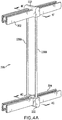
- Figs. 4A-4G show details of parallel bar hanger such as hanger 206 supporting bar 304 from bar 302 in Fig. 1 .
- the hanger 206 includes two vertical segments 230A, 230B. At the top and the bottom, the two segments 230A, 230B have their ends imbedded in identical W-shaped bases 232, shown in more detail in Figs. 9B-9E.
- the base 232 forms two channels 234, 236 with a wall 238 separating the two channels.
- the base 232 is further formed with two metallic springs or clips 240, 242. Clip 240 is electrically attached to segment 230A within the base 232, and clip 242 is connected to segment 230B.
- base 232 is made of a non-conductive material and is overmolded to cover portions of the clips 240, 242 and segments 230A, 230B.
- the two bases 232 have a single, unitary structure.
- at least the top base is made of two sections 232A, 232B that snap together along line 232 forming an interference fit therebetween.
- the bases 232 as sized and shaped so that they fit over and engage the bars 302, 304.
- the clips 240, 242 are sized and shaped so that they engage the rails 356, 358.
- the clips 240, 242 have a flat section 244 sized and shaped to snap into the channels 356, 358 of the bars 302, 304. In this manner not only do the clips 240, 242 provide a solid electrical contact with the rails 356, 358 but they also stabilize the hangers on the bars and insure that the lower bar 304 remains stiff and does move around in use.
- the clips may be made from beryllium copper.
- Hanger 208 has a similar configuration however the clips need not be connected electrically to the hanger segments. In other cases, for example, in the configuration shown in Fig. 2 , hangers 222 do provide electrical connection to bars 304A and 306.
- the hanger segments 230A, 230B are provided in various lengths as required to obtain the various systems described above, and they are preferably made in the shape of rods of a stiff but somewhat springy material having shape memory such as a phosphor/bronze alloy. Preferably except where an electrical contact is required, the rods are covered or painted with a thin electrically insulating material.
- the hangers can be installed by separating the two segments 230A, 230B, passing the ends of the respective bars 302, 304... between the segments, then lowering or raising the bars toward the respective bases 232 and then snapping the bases onto the bars into the configurations shown in Figs. 4F and 4G .
- the power bars extend perpendicularly to each other.
- bars 302 and 304 are perpendicular to each other.
- These bars are interconnected using a hanger 222 shown in Figs. 4H-4J .
- This hanger 222 has two segments 272A, 272B and a base 232 similar to the base 232 in Figs. 9A-9G.
- at the bottom hanger 222 is provided with a different base 274.
- This base 274 is formed with two side wings 274A, 274B and a center wall 274C.
- Clips 276, 278 are provided on the center wall 274C and are connected electrically with segments 272A, 272B, respectively as show in Fig. 4J .
- the center wall 274C is made with two holes 280A, 280B with the lower ends of segments 272A, 272B extending into the holes and being secured to the base 222.
- the base 270 is sized and shaped to engage and support the power bar segments 304A, 304B of a bar 304A with the segments 272A, 272B providing power to these power bar segments.
- the base 232 engages the segments of the bar 302 in the manner discussed above.
- Figs. 5A-5E show details of a light bar 600.
- the light bar 600 includes a substantially horizontal body 602 having approximately the same width as power bar 300 and two end connectors 604, 606.
- the connectors 604, 606 may have a similar structure to the one shown in Fig. 4G et al with respective clips to attach the light bar 600 to the power bar 300 securely.
- a top surface 608 of the light bar is made of a transparent or translucent material to allow light from a plurality of LEDs 610 disposed within the body 602. In the embodiment of Figs. 5A-5D the light bar 600 is configured to be projected upwardly.
- the bar 600 can be turned upside down so that the LEDS 610 are pointed downwardly and the bar 600 can be connected to power bar 300 by pushing upward, as shown in Fig. 5D .
- the light bar 600 can have any desired size, such as 12", 24", 36", etc.
- the light bar 600 is sized and shaped so that once it is mounted on the power bar 300, a sufficient gap 607 is formed therebetween for a connector 200 as shown in Fig. 5C .
- FIG. 5E shows a cross sectional view of a connector 604 that has a similar structure to the connector shown in Fig. 4G with elements 342A, 354A, 358A. 360A in Fig. 5E having the same shape and function as their respective counterparts 352, 354, 356, 358, 360 in Fig. 4G .
- clips 340A, 342A are mechanically and electrically connected to respective blades 630, 632 that rise straight up and are provided at their upper ends with screws 634, 636.
- the blades 630, 632 slip into the body 600(through suitable holes, not shown) and are attached thereto by screws 634, 636.
- the blades 630, 632 are connected by other members (or via screws 634, 636) electrically to a circuit board and provide power to the LEDs 608.
- the connector 606 has a similar structure to connector 604 but does not provide electrical power and is used to engage the inner rails of the bar 300 and support the light bar 600 on the power bar 300.
- the bar light 600 is installed in the configuration of either Fig. 5C or 5D by pressing the body 602 toward the bar 300 as shown in Fig. A with the clips entering gap 303 and engaging the rails within the bar 300. These components are shaped to form an interference fit between the clips 340A, 343A and the rails 360A.
- an L-shaped tool 620 is provided having two legs 622, 624 as shown in Figs. 5F and 5G .
- the tool 620 is wider than the gap 303 in bar 300 so it can be sited comfortable on top of bar 300.
- the tool 620 is then positioned so its leg 622 comes in contact with the bottom surface 612 of light bar 600. Pushing the tool 620 in direction A causes the tool 620 to lift the light bar 600 up and away from the power bar 300 as shown by arrow B.
- the light bar 600 has been described as being attached to the power bar of a modular lighting system shown in Figs. 1-4 .
- the light bar 600 can be used in any lighting system as well.
- the spacing between the power bar and the light bar may be fairly small so that the hangers discussed above may be difficult to install therebetween.
- the present invention provides a hanger with a smaller profile so that it can fit easier in smaller spaces.
- hanger 1000 includes a base 1001 with main body 1002 and a cover 1004.
- the hanger 1000 is going to be attached to a power bar 300 having the structure shown in Figs. 3A-3I
- the main body 1002 is in the shape of a W with two side arms 1010 and a center portion 1012 supported on a horizontal wall 1014.
- Adjacent to (and preferably supported by) the center portion 1012 are two metallic clips 1016 arranged and constructed to engage the respective conductive rails (such as rails 360 in Fig. 3E ) within the bar 300.
- the side bars 1010 and the base 1014 are formed on their outer surfaces with an external channel or indentation 1018.
- the cover 1004 is U-shaped and has two side wings 1020 and a center portion 1022.
- the side wings 1020 are formed with opposed ribs 1024 on their internal surfaces 1020A.
- the cover 1004 is shaped and sized so that it fits over the main body 1002.
- cover 1004 and main body 1002 are pushed toward each other as indicated by arrows R with its side wings 1020 and ribs 1024 slide into the indentations 1018 thereby forming a unitary hanger base 1001 as shown in Fig. 6B .
- the clips 1014, 1016 snap unto rails 360 of bar 300 thereby making electrical contact therewith and at the same time forming an interference fit between the hanger base 1000 and bar 300.
- hanger 1000 further includes an electric chord 1030 with two internal wires (not shown).
- the internal wires are electrically coupled to the clips 1014, 1016.
- cord 1030 is used to hang various pendants 1040, 1042, 1044 on bar 300 with each pendant 1040, 1042, 1044 being mechanically attached to the bar 300 and receiving from bar 300 through the respective hanger 1000.
- Figs.6C and 6D show a hanger 1000A.
- This hanger 1000A includes a base 1001A and two rods 1030A, 1030B.
- the base 1001 A is formed of a main body 1002A and a cover 1004A.
- Main body 1002A includes a bottom wall 1060 and two vertical side walls 1062 a central wall 1064. The side walls and a central wall form two cavities receiving the segments of the power bar 300.
- Central wall 1064 holds two clips (not shown) similar to clips 1016.
- the two rods 1030A, 1030B depend on and extend downwardly from bottom wall 1060. Connectors (not shown) are used to electrically connect each of the rods 1030A, 1030B to one of the clips.
- Cover 1004A includes a flat wall 1070 and four dependent vertical walls 1070. Each of the walls 1070 is formed with a respect rib 1072 extending inwardly. The cover 1004A snaps over the main body 1002A in an interference fit to form base 1001 A.
- the hanger 1000A is used as follows.
- the main body 1002A and the cover 1004A are positioned as shown in Fig. 6C on the bottom and top of the power bar 300.
- the two members are snapped together in interference fit to form a single base 1001 A entrapping the bar 300 therebetween.
- the bottoms of rods 1030A, 1030B, as at 1080, are attached to respective pendant so that the hanger 1000A provides both mechanical support and electric power to a respective pendant.
- Hanger 1000B in Figs. 6E and 6F is similar to hanger 1000A and it includes a base 1001A having the structure illustrated in Fig. 6C , a base 232 having the structure shown in Figs. 4A-4G , and two rods 1080, 1082.
- the upper ends of rods 1080, 1082 engage the base 232 while the lower ends engage or are connected to the main body 1002A of base 1001 A.
- the main body 1002A and the cover 1004A are snapped together around a bar 302, as indicated by arrows P into the configuration shown in Fig. 6F .
- the upper base 232 is disposed around a power bar 302X.
- Figs. 6E, 6F show hanger 1001 B can be used to interconnect two vertically spaced power bars 302 and 302X.
Landscapes
- Engineering & Computer Science (AREA)
- General Engineering & Computer Science (AREA)
- Non-Portable Lighting Devices Or Systems Thereof (AREA)
Applications Claiming Priority (2)
| Application Number | Priority Date | Filing Date | Title |
|---|---|---|---|
| US201662419505P | 2016-11-09 | 2016-11-09 | |
| US15/584,171 US10174923B2 (en) | 2016-11-09 | 2017-05-02 | Hanger for a modular lighting system having a main body with two channels to accommodate two segments of a power bar |
Publications (1)
| Publication Number | Publication Date |
|---|---|
| EP3321569A1 true EP3321569A1 (fr) | 2018-05-16 |
Family
ID=60293801
Family Applications (1)
| Application Number | Title | Priority Date | Filing Date |
|---|---|---|---|
| EP17200563.9A Withdrawn EP3321569A1 (fr) | 2016-11-09 | 2017-11-08 | Cintre à profil bas pour système d'éclairage modulaire |
Country Status (3)
| Country | Link |
|---|---|
| US (1) | US10174923B2 (fr) |
| EP (1) | EP3321569A1 (fr) |
| CA (1) | CA2984672C (fr) |
Cited By (2)
| Publication number | Priority date | Publication date | Assignee | Title |
|---|---|---|---|---|
| EP3876364A1 (fr) * | 2020-03-06 | 2021-09-08 | H4X e.U. | Système d'éclairage de voie |
| WO2022022985A1 (fr) * | 2020-07-28 | 2022-02-03 | Zumtobel Lighting Gmbh | Composant de réglette lumineuse et système de réglette lumineuse |
Families Citing this family (4)
| Publication number | Priority date | Publication date | Assignee | Title |
|---|---|---|---|---|
| USD1008494S1 (en) * | 2020-09-25 | 2023-12-19 | Signify Holding B.V. | Lighting fixture |
| USD1035966S1 (en) * | 2020-09-25 | 2024-07-16 | Signify Holding B.V. | Lighting fixture |
| DE102021202972A1 (de) | 2021-03-25 | 2022-09-29 | H4X E.U. | Beleuchtungsanordnung |
| WO2026061830A1 (fr) * | 2024-09-18 | 2026-03-26 | Signify Holding B.V. | Attache de montage pour un dispositif d'éclairage dans un environnement agricole |
Citations (4)
| Publication number | Priority date | Publication date | Assignee | Title |
|---|---|---|---|---|
| DE8708815U1 (de) * | 1987-06-25 | 1987-11-05 | Mawa Design Martin Wallroth GmbH, 1000 Berlin | Halogenbogenleuchte |
| EP0379244A1 (fr) * | 1989-01-20 | 1990-07-25 | Janse Lichtreklame B.V. | Dispositif d'éclairage pour la publicité |
| WO2016132361A1 (fr) * | 2015-02-17 | 2016-08-25 | Chocolate Lighting Company Ltd | Système d'éclairage sur rail |
| EP3196547A1 (fr) * | 2016-01-07 | 2017-07-26 | Robert A. Sonneman | Système d'éclairage modulaire utilisant des éléments de suspension et des barres d'alimentation |
Family Cites Families (111)
| Publication number | Priority date | Publication date | Assignee | Title |
|---|---|---|---|---|
| FR608016A (fr) | 1925-12-16 | 1926-07-13 | Dispositif pour la concentration des flux lumineux émanant de sources différentes sur une même surface | |
| US2292395A (en) | 1940-02-06 | 1942-08-11 | Pierce John B Foundation | Composite electricity conductor unit |
| US3716031A (en) | 1971-02-26 | 1973-02-13 | Rowburg D | Quick release lariat honda |
| US3748463A (en) | 1972-08-30 | 1973-07-24 | Sormani Spa | Floor lamp |
| IT1182537B (it) | 1985-07-24 | 1987-10-05 | Sames Spa | Sistema di illuminazione d ambienti |
| FR2588713A1 (fr) | 1985-10-16 | 1987-04-17 | Foucault Gerard | Dispositif pour l'alimentation et la fixation instantanee de sources tres basse-tension |
| USD301304S (en) | 1986-03-13 | 1989-05-30 | Lutron Electronics Co., Inc. | Mounting clip for releasably retaining an electric lamp control unit or similar article |
| US4723747A (en) | 1986-10-24 | 1988-02-09 | Capri Lighting | Bar hangers for recessed lighting fixtures |
| US4763870A (en) | 1987-02-11 | 1988-08-16 | Fortran Traffic Systems Limited | Traffic signal head |
| DE3742206A1 (de) | 1987-12-12 | 1989-06-22 | Josef Soelken Gmbh & Co Kg | Installationsteil fuer leuchten tragende niederspannungs-stromschienen |
| USD317058S (en) | 1989-08-14 | 1991-05-21 | Sonneman Design Group, Inc. | Wall mounted lamp assembly |
| USD320465S (en) | 1989-08-14 | 1991-10-01 | Sonneman Design Group Inc. | Hanging lamp assembly |
| US5025355A (en) | 1989-11-03 | 1991-06-18 | Harwood Ronald P | Combination lighting fixture and graphic display means |
| US5105349A (en) | 1990-09-24 | 1992-04-14 | Falls John W | Motorized chandelier lift system |
| FR2685947A1 (fr) | 1992-01-06 | 1993-07-09 | Applic Tech Decoratives Ec | Dispositif de support et d'alimentation pour un eclairage a tres basse tension. |
| US5440469A (en) | 1994-04-08 | 1995-08-08 | Gomes; Roy | Low voltage track lighting fixture |
| DE4414046C2 (de) | 1994-04-22 | 1996-02-29 | Leonhard Bopp | Beleuchtungsanlage für Niederspannung zur Decken- oder Wandmontage |
| USD360046S (en) | 1994-07-01 | 1995-07-04 | Yazaki Industrial Chemical Co., Ltd. | Clamp-on holder for LED lamp |
| DE19510507C2 (de) | 1995-03-23 | 1999-11-18 | Alulite Lichtsysteme Gmbh | Elektrisches Leuchtensystem |
| USD392407S (en) | 1995-08-30 | 1998-03-17 | Phoenix Products Company, Inc. | Light fixture |
| US5833358A (en) | 1995-11-21 | 1998-11-10 | Aci The Display People | Extruded track lighting system |
| US5584576A (en) | 1995-11-27 | 1996-12-17 | Wei Hong; Shen | Clamping and connecting structure for track lights |
| DE29705852U1 (de) | 1997-04-02 | 1997-05-15 | Chen, Meiric, Hsinchuan, Taipeh | Beleuchtungseinrichtung |
| DE19849101A1 (de) | 1997-10-24 | 1999-04-29 | Guenter Loof | Stromschienensystem |
| US6179442B1 (en) | 1998-09-21 | 2001-01-30 | S & S Stars, Llc | Christmas star light device |
| US6241369B1 (en) | 1998-11-20 | 2001-06-05 | Cooper Technologies Company | Quick mount fixture |
| US6135615A (en) | 1999-04-28 | 2000-10-24 | Lee; Cheng-Ping | Lamp suspension track assembly |
| US6244733B1 (en) | 2000-02-25 | 2001-06-12 | Juno Manufacturing, Inc. | Low voltage track lighting system |
| GB2361988B (en) | 2000-05-05 | 2004-03-03 | Avimo Ltd | Illumination system |
| US6489748B1 (en) | 2000-12-01 | 2002-12-03 | Cisco Technology, Inc. | Split backplane power system |
| US6341979B1 (en) | 2001-01-04 | 2002-01-29 | Monster Cable Products, Inc. | Electrical connector |
| US6769790B2 (en) | 2001-04-12 | 2004-08-03 | Fruehm Hermann | Theatrical lighting system with moving lights |
| US6676281B2 (en) | 2001-05-23 | 2004-01-13 | Sea Gull Lighting Products, Inc. | Rail lighting system |
| US6409524B1 (en) | 2001-07-30 | 2002-06-25 | Jack V. Miller | Side-mounted tracklight system |
| US6716042B2 (en) | 2002-07-05 | 2004-04-06 | Michael Lin | Track system of projector lamp and electrical connection device assembly thereof |
| US7172332B2 (en) * | 2003-02-14 | 2007-02-06 | Tech Lighting L.L.C. | Field bendable line voltage track lighting system |
| DE202004001178U1 (de) | 2004-01-27 | 2004-05-13 | Wisam Enterprises Co., Ltd. | Stehlampe, insbesondere mit verschiebbaren Lampenschirmen zur Installierung einer beliebigen Anzahl von Glühbirnen |
| USD507374S1 (en) | 2004-03-05 | 2005-07-12 | Tseng Mei Enterprise Co., Ltd. | Light |
| CA2461247A1 (fr) | 2004-03-18 | 2005-09-18 | Simon-Victor Benghozi | Projecteurs sur rails |
| US20080190043A1 (en) | 2004-08-31 | 2008-08-14 | Waltraud Beckmann | Space Division System with Material Support Linkage |
| US7397384B1 (en) | 2005-02-11 | 2008-07-08 | Genlyte Thomas Group, Llc | Track lighting system current limiting device |
| ATE513287T1 (de) * | 2005-04-06 | 2011-07-15 | Hemsson B V | Anordnung eines mastes und abrichtvorrichtung, abrichtvorrichtung für eine derartige anordnung und verfahren zum abrichten eines mastes |
| US7661229B2 (en) | 2005-05-12 | 2010-02-16 | Worthington Armstrong Venture | Electrical conductivity in a suspended ceiling system |
| US8061865B2 (en) | 2005-05-23 | 2011-11-22 | Philips Solid-State Lighting Solutions, Inc. | Methods and apparatus for providing lighting via a grid system of a suspended ceiling |
| KR20060131248A (ko) | 2005-06-15 | 2006-12-20 | 삼성전자주식회사 | 백라이트 어셈블리 및 이를 갖는 액정표시장치 |
| ITMI20050301U1 (it) | 2005-08-26 | 2007-02-27 | Sarno Spa | Dispositivo di illuminazione con partalampada modulare e mobile per espositori e-o spazi di esposizione |
| US7364346B2 (en) | 2005-09-06 | 2008-04-29 | The L.D. Kichler Co. | Low voltage track lighting assembly and system |
| US7520762B2 (en) | 2005-12-30 | 2009-04-21 | Cooper Technologies Company | Lighting system and method |
| US7503778B2 (en) | 2005-12-30 | 2009-03-17 | Cooper Technologies Company | Lighting system and method |
| DE102006019194A1 (de) * | 2006-04-21 | 2007-10-25 | Semperlux Ag - Lichttechnische Werke - | Mehrseitige Beleuchtungsanordnung mit Entblendung |
| US8616871B2 (en) | 2006-08-01 | 2013-12-31 | Galomb, Inc. | Hand operated injection molding apparatus |
| US7806913B2 (en) | 2006-08-16 | 2010-10-05 | Depuy Spine, Inc. | Modular multi-level spine stabilization system and method |
| US7794132B2 (en) | 2006-11-14 | 2010-09-14 | Troy-Csl Lighting, Inc. | Lighting system |
| CN200986123Y (zh) | 2006-12-06 | 2007-12-05 | 区炳文 | 磁接式低压灯具 |
| US7507005B1 (en) | 2007-01-30 | 2009-03-24 | Genlyte Thomas Group Llc | Sliding flexible track lighting |
| US7520763B1 (en) | 2007-06-29 | 2009-04-21 | Genlyte Thomas Group Llc | Track lighting system with dependent lamp cord |
| KR100904633B1 (ko) | 2007-08-21 | 2009-06-25 | 주식회사 필룩스 | 형광램프장치 |
| US7654834B1 (en) | 2008-05-05 | 2010-02-02 | Genlyte Thomas Group, Llc | Track lighting assembly |
| USD632423S1 (en) | 2008-05-14 | 2011-02-08 | Total Precision Cabinetry, Inc. | Modular bulkhead |
| US7571736B1 (en) | 2008-08-22 | 2009-08-11 | Wai Chuen Chu | Illuminated umbrella |
| US7798824B2 (en) | 2008-08-28 | 2010-09-21 | Juno Manufacturing, Inc. | Adapter for line voltage track |
| USD595884S1 (en) | 2008-12-30 | 2009-07-07 | S-Sun Enterprise Co., Ltd | Bicycle light |
| USD611169S1 (en) | 2009-02-09 | 2010-03-02 | Harder Willard J | Deck rail |
| DE202010005878U1 (de) | 2009-04-23 | 2011-04-21 | Müessli, Daniel | Beleuchtungssystem |
| USD617034S1 (en) | 2009-08-12 | 2010-06-01 | U.S. Pole Company, Inc. | Lighting fixture |
| WO2011056782A1 (fr) | 2009-11-04 | 2011-05-12 | Hogue Surgical, Llc | Connecteur pour fibre optique réglable |
| US9136659B2 (en) | 2009-12-15 | 2015-09-15 | Koninklijke Philips N.V. | Downward compatible voltage track lighting system |
| USD620168S1 (en) | 2010-01-04 | 2010-07-20 | Eglo Leuchten Gmbh | Light fixture |
| US8523378B2 (en) | 2010-03-01 | 2013-09-03 | Minka Lighting, Inc. | Combination ceiling fan and track light |
| US8398276B2 (en) | 2010-03-12 | 2013-03-19 | Tempo Industries, Llc | Wall mounted aisle, step and corridor light system |
| US8733710B1 (en) | 2010-04-13 | 2014-05-27 | Marken Global, LLC | Clamp display system |
| US9387268B2 (en) | 2010-06-01 | 2016-07-12 | Alexander Farren | Compositions and methods for UV sterilization |
| US7955125B1 (en) | 2010-10-14 | 2011-06-07 | Souriau Usa, Inc. | Electrical connector with one end threadably connected to a junction box and other end configured to be connected to a mating electrical connector |
| USD648470S1 (en) | 2010-12-01 | 2011-11-08 | Light Muse, LLC | Light pod |
| USD649692S1 (en) | 2011-01-04 | 2011-11-29 | LEDs ON | Extrusion for LED-based lighting apparatus |
| US8714775B2 (en) | 2011-04-11 | 2014-05-06 | Swarovski Lighting, Ltd. | Light fixtures, methods of suspending a plurality of light sources, an ornament mounting, and a method for mounting an ornament |
| US8794804B2 (en) | 2011-10-18 | 2014-08-05 | Orion Energy Systems, Inc. | System and method for supporting and leveling a light fixture |
| EP2615700B1 (fr) | 2012-01-11 | 2015-03-11 | OSRAM GmbH | Module d'éclairage |
| US9673582B2 (en) * | 2012-01-17 | 2017-06-06 | Joseph Guilmette | Modular housing and track assemblies for tubular lamps |
| USD680673S1 (en) | 2012-03-19 | 2013-04-23 | Jonathan E. Levine | Lighting device |
| USD671670S1 (en) | 2012-04-09 | 2012-11-27 | Sonneman Robert A | Light fixture with multiple supports |
| US9360196B2 (en) | 2012-06-15 | 2016-06-07 | Rtc Industries, Inc. | Low voltage power supply for a merchandise display system |
| USD689221S1 (en) | 2012-07-23 | 2013-09-03 | Rafi Isaac | Waterproof lamp |
| CN105264290A (zh) | 2012-11-20 | 2016-01-20 | 莫列斯公司 | 灯固持座以及用于灯固持座的led模块 |
| DE102013100435A1 (de) | 2013-01-16 | 2014-07-17 | Conductix-Wampfler Gmbh | Verbindungselement für eine Schleifleitung, Schleifleitung und Verfahren zur Herstellung einer Schleifleitung |
| WO2014135554A2 (fr) | 2013-03-07 | 2014-09-12 | Koninklijke Philips N.V. | Système d'éclairage, piste et module d'éclairage pour celui-ci |
| US8967573B2 (en) | 2013-03-14 | 2015-03-03 | Dental Equipment, Llc | Modular, bypass track and carriage system for overhead-mounted lights and other devices |
| CA150672S (en) | 2013-04-09 | 2014-06-12 | Peter Joseph Maher | Stick holder |
| USD739070S1 (en) | 2013-04-15 | 2015-09-15 | Artemide S.P.A. | Table lamp |
| NL2011072C2 (nl) | 2013-07-01 | 2015-01-06 | Flowmagic Holding B V | Samenstel van spanningsrail, adapter en led-tube, adapter kennelijk geschikt voor het gebruikmaken van het samenstel en werkwijze voor het aanbrengen van verlichtingselementen. |
| CA2859584A1 (fr) | 2013-08-15 | 2015-02-15 | Evolution Lighting Llc | Luminaires interchangeables pour systeme d'eclairage mural et sur rail |
| US9464772B2 (en) | 2014-01-13 | 2016-10-11 | Cordelia Lighting Inc. | Ambient directional combination light fixture |
| CN105299524B (zh) | 2014-05-26 | 2018-06-05 | 赛尔富电子有限公司 | 一种led条形轨道灯 |
| WO2016150564A2 (fr) | 2015-03-20 | 2016-09-29 | Hesalight A/S | Système d'éclairage à rail magnétique modulaire |
| USD765296S1 (en) | 2015-05-04 | 2016-08-30 | Ningbo Loyal Lighting Technology Co., Ltd. | Light fixture |
| CN205261379U (zh) | 2015-12-03 | 2016-05-25 | 江门市普锐高科照明有限公司 | 多角度防眩光自然对流轨道灯 |
| US9879845B2 (en) * | 2016-01-07 | 2018-01-30 | Robert A. Sonneman | Modular lighting system using hangers and power bars |
| USD773101S1 (en) | 2016-01-11 | 2016-11-29 | Robert A. Sonneman | Lighting fixture |
| USD772467S1 (en) | 2016-01-08 | 2016-11-22 | Robert A. Sonneman | Light fixture |
| USD773099S1 (en) | 2016-01-12 | 2016-11-29 | Robert A. Sonneman | Circular lighting fixture |
| USD773725S1 (en) | 2016-05-13 | 2016-12-06 | Robert A. Sonneman | Canopy for light fixtures with multiple supports |
| USD773719S1 (en) | 2016-05-25 | 2016-12-06 | Robert A. Sonneman | Lighting system |
| USD775397S1 (en) | 2016-05-27 | 2016-12-27 | Robert A. Sonneman | Lighting fixture |
| USD779714S1 (en) | 2016-06-30 | 2017-02-21 | Robert A. Sonneman | Insulated hanger with a cover for a lighting system |
| USD779712S1 (en) | 2016-06-30 | 2017-02-21 | Robert A. Sonneman | W-shaped bar connector for a lighting system |
| USD779713S1 (en) | 2016-06-30 | 2017-02-21 | Robert A. Sonneman | Insulated hanger for a lighting system |
| USD772475S1 (en) | 2016-07-05 | 2016-11-22 | Robert A. Sonneman | Single bar hanger for a lighting system |
| USD779715S1 (en) | 2016-08-26 | 2017-02-21 | Robert A. Sonneman | Right angle power bar suspender for a lighting system |
| USD779113S1 (en) | 2016-08-26 | 2017-02-14 | Robert A. Sonneman | Parallel power bar suspender for a lighting system |
| USD779437S1 (en) | 2016-08-31 | 2017-02-21 | Robert A. Sonneman | Power rod connector for a lighting system |
| USD782990S1 (en) | 2016-09-07 | 2017-04-04 | Robert A. Sonneman | Power box for a lighting system |
-
2017
- 2017-05-02 US US15/584,171 patent/US10174923B2/en active Active
- 2017-11-02 CA CA2984672A patent/CA2984672C/fr not_active Expired - Fee Related
- 2017-11-08 EP EP17200563.9A patent/EP3321569A1/fr not_active Withdrawn
Patent Citations (4)
| Publication number | Priority date | Publication date | Assignee | Title |
|---|---|---|---|---|
| DE8708815U1 (de) * | 1987-06-25 | 1987-11-05 | Mawa Design Martin Wallroth GmbH, 1000 Berlin | Halogenbogenleuchte |
| EP0379244A1 (fr) * | 1989-01-20 | 1990-07-25 | Janse Lichtreklame B.V. | Dispositif d'éclairage pour la publicité |
| WO2016132361A1 (fr) * | 2015-02-17 | 2016-08-25 | Chocolate Lighting Company Ltd | Système d'éclairage sur rail |
| EP3196547A1 (fr) * | 2016-01-07 | 2017-07-26 | Robert A. Sonneman | Système d'éclairage modulaire utilisant des éléments de suspension et des barres d'alimentation |
Cited By (5)
| Publication number | Priority date | Publication date | Assignee | Title |
|---|---|---|---|---|
| EP3876364A1 (fr) * | 2020-03-06 | 2021-09-08 | H4X e.U. | Système d'éclairage de voie |
| AT523583A3 (de) * | 2020-03-06 | 2021-12-15 | H4X Eu | Schienenleuchtensystem |
| AT523583B1 (de) * | 2020-03-06 | 2022-06-15 | H4X Eu | Schienenleuchtensystem |
| WO2022022985A1 (fr) * | 2020-07-28 | 2022-02-03 | Zumtobel Lighting Gmbh | Composant de réglette lumineuse et système de réglette lumineuse |
| AT17825U1 (de) * | 2020-07-28 | 2023-03-15 | Zumtobel Lighting Gmbh At | Lichtbandkomponente und Lichtbandsystem |
Also Published As
| Publication number | Publication date |
|---|---|
| CA2984672C (fr) | 2020-03-10 |
| US20180128470A1 (en) | 2018-05-10 |
| CA2984672A1 (fr) | 2018-05-09 |
| US10174923B2 (en) | 2019-01-08 |
Similar Documents
| Publication | Publication Date | Title |
|---|---|---|
| EP3321569A1 (fr) | Cintre à profil bas pour système d'éclairage modulaire | |
| US10156349B2 (en) | Method and apparatus for hanging lighting fixtures | |
| CA2984652C (fr) | Support de barre d'alimentation destine a un systeme d'eclairage modulaire | |
| CA2984681C (fr) | Logement cylindrique destine a un systeme d'eclairage modulaire | |
| EP3470733B1 (fr) | Système d'éclairage modulaire utilisant des éléments de suspension et des barres d'alimentation | |
| CA2984671C (fr) | Barre d'eclairage d'un systeme d'eclairage | |
| US20180128466A1 (en) | Ring power bar hanger for modular lighting fixture | |
| EP3321568A1 (fr) | Lumières supportées latéralement | |
| CA2954263C (fr) | Systeme d'eclairage modulaire employant des supports et des barres d'alimentation |
Legal Events
| Date | Code | Title | Description |
|---|---|---|---|
| PUAI | Public reference made under article 153(3) epc to a published international application that has entered the european phase |
Free format text: ORIGINAL CODE: 0009012 |
|
| STAA | Information on the status of an ep patent application or granted ep patent |
Free format text: STATUS: THE APPLICATION HAS BEEN PUBLISHED |
|
| AK | Designated contracting states |
Kind code of ref document: A1 Designated state(s): AL AT BE BG CH CY CZ DE DK EE ES FI FR GB GR HR HU IE IS IT LI LT LU LV MC MK MT NL NO PL PT RO RS SE SI SK SM TR |
|
| AX | Request for extension of the european patent |
Extension state: BA ME |
|
| RAP1 | Party data changed (applicant data changed or rights of an application transferred) |
Owner name: CONTEMPORARY VISIONS, LLC |
|
| RIN1 | Information on inventor provided before grant (corrected) |
Inventor name: SONNEMAN, ROBERT, A. |
|
| STAA | Information on the status of an ep patent application or granted ep patent |
Free format text: STATUS: REQUEST FOR EXAMINATION WAS MADE |
|
| STAA | Information on the status of an ep patent application or granted ep patent |
Free format text: STATUS: EXAMINATION IS IN PROGRESS |
|
| 17P | Request for examination filed |
Effective date: 20181029 |
|
| RBV | Designated contracting states (corrected) |
Designated state(s): AL AT BE BG CH CY CZ DE DK EE ES FI FR GB GR HR HU IE IS IT LI LT LU LV MC MK MT NL NO PL PT RO RS SE SI SK SM TR |
|
| 17Q | First examination report despatched |
Effective date: 20181128 |
|
| STAA | Information on the status of an ep patent application or granted ep patent |
Free format text: STATUS: THE APPLICATION IS DEEMED TO BE WITHDRAWN |
|
| 18D | Application deemed to be withdrawn |
Effective date: 20230127 |