EP3321588B1 - Gasturbinenbrennkammer - Google Patents
Gasturbinenbrennkammer Download PDFInfo
- Publication number
- EP3321588B1 EP3321588B1 EP17201213.0A EP17201213A EP3321588B1 EP 3321588 B1 EP3321588 B1 EP 3321588B1 EP 17201213 A EP17201213 A EP 17201213A EP 3321588 B1 EP3321588 B1 EP 3321588B1
- Authority
- EP
- European Patent Office
- Prior art keywords
- aft
- combustor
- liner
- circumferential edge
- linear
- Prior art date
- Legal status (The legal status is an assumption and is not a legal conclusion. Google has not performed a legal analysis and makes no representation as to the accuracy of the status listed.)
- Active
Links
Images




Classifications
-
- F—MECHANICAL ENGINEERING; LIGHTING; HEATING; WEAPONS; BLASTING
- F23—COMBUSTION APPARATUS; COMBUSTION PROCESSES
- F23M—CASINGS, LININGS, WALLS OR DOORS SPECIALLY ADAPTED FOR COMBUSTION CHAMBERS, e.g. FIREBRIDGES; DEVICES FOR DEFLECTING AIR, FLAMES OR COMBUSTION PRODUCTS IN COMBUSTION CHAMBERS; SAFETY ARRANGEMENTS SPECIALLY ADAPTED FOR COMBUSTION APPARATUS; DETAILS OF COMBUSTION CHAMBERS, NOT OTHERWISE PROVIDED FOR
- F23M5/00—Casings; Linings; Walls
- F23M5/04—Supports for linings
-
- F—MECHANICAL ENGINEERING; LIGHTING; HEATING; WEAPONS; BLASTING
- F23—COMBUSTION APPARATUS; COMBUSTION PROCESSES
- F23R—GENERATING COMBUSTION PRODUCTS OF HIGH PRESSURE OR HIGH VELOCITY, e.g. GAS-TURBINE COMBUSTION CHAMBERS
- F23R3/00—Continuous combustion chambers using liquid or gaseous fuel
- F23R3/002—Wall structures
-
- F—MECHANICAL ENGINEERING; LIGHTING; HEATING; WEAPONS; BLASTING
- F01—MACHINES OR ENGINES IN GENERAL; ENGINE PLANTS IN GENERAL; STEAM ENGINES
- F01D—NON-POSITIVE DISPLACEMENT MACHINES OR ENGINES, e.g. STEAM TURBINES
- F01D9/00—Stators
- F01D9/02—Nozzles; Nozzle boxes; Stator blades; Guide conduits, e.g. individual nozzles
- F01D9/023—Transition ducts between combustor cans and first stage of the turbine in gas-turbine engines; their cooling or sealings
-
- F—MECHANICAL ENGINEERING; LIGHTING; HEATING; WEAPONS; BLASTING
- F23—COMBUSTION APPARATUS; COMBUSTION PROCESSES
- F23M—CASINGS, LININGS, WALLS OR DOORS SPECIALLY ADAPTED FOR COMBUSTION CHAMBERS, e.g. FIREBRIDGES; DEVICES FOR DEFLECTING AIR, FLAMES OR COMBUSTION PRODUCTS IN COMBUSTION CHAMBERS; SAFETY ARRANGEMENTS SPECIALLY ADAPTED FOR COMBUSTION APPARATUS; DETAILS OF COMBUSTION CHAMBERS, NOT OTHERWISE PROVIDED FOR
- F23M5/00—Casings; Linings; Walls
- F23M5/08—Cooling thereof; Tube walls
- F23M5/085—Cooling thereof; Tube walls using air or other gas as the cooling medium
-
- F—MECHANICAL ENGINEERING; LIGHTING; HEATING; WEAPONS; BLASTING
- F23—COMBUSTION APPARATUS; COMBUSTION PROCESSES
- F23R—GENERATING COMBUSTION PRODUCTS OF HIGH PRESSURE OR HIGH VELOCITY, e.g. GAS-TURBINE COMBUSTION CHAMBERS
- F23R3/00—Continuous combustion chambers using liquid or gaseous fuel
- F23R3/02—Continuous combustion chambers using liquid or gaseous fuel characterised by the air-flow or gas-flow configuration
- F23R3/04—Air inlet arrangements
- F23R3/06—Arrangement of apertures along the flame tube
-
- F—MECHANICAL ENGINEERING; LIGHTING; HEATING; WEAPONS; BLASTING
- F23—COMBUSTION APPARATUS; COMBUSTION PROCESSES
- F23R—GENERATING COMBUSTION PRODUCTS OF HIGH PRESSURE OR HIGH VELOCITY, e.g. GAS-TURBINE COMBUSTION CHAMBERS
- F23R3/00—Continuous combustion chambers using liquid or gaseous fuel
- F23R3/42—Continuous combustion chambers using liquid or gaseous fuel characterised by the arrangement or form of the flame tubes or combustion chambers
- F23R3/50—Combustion chambers comprising an annular flame tube within an annular casing
-
- F—MECHANICAL ENGINEERING; LIGHTING; HEATING; WEAPONS; BLASTING
- F23—COMBUSTION APPARATUS; COMBUSTION PROCESSES
- F23R—GENERATING COMBUSTION PRODUCTS OF HIGH PRESSURE OR HIGH VELOCITY, e.g. GAS-TURBINE COMBUSTION CHAMBERS
- F23R3/00—Continuous combustion chambers using liquid or gaseous fuel
- F23R3/42—Continuous combustion chambers using liquid or gaseous fuel characterised by the arrangement or form of the flame tubes or combustion chambers
- F23R3/60—Support structures; Attaching or mounting means
-
- F—MECHANICAL ENGINEERING; LIGHTING; HEATING; WEAPONS; BLASTING
- F23—COMBUSTION APPARATUS; COMBUSTION PROCESSES
- F23R—GENERATING COMBUSTION PRODUCTS OF HIGH PRESSURE OR HIGH VELOCITY, e.g. GAS-TURBINE COMBUSTION CHAMBERS
- F23R2900/00—Special features of, or arrangements for continuous combustion chambers; Combustion processes therefor
- F23R2900/03041—Effusion cooled combustion chamber walls or domes
-
- F—MECHANICAL ENGINEERING; LIGHTING; HEATING; WEAPONS; BLASTING
- F23—COMBUSTION APPARATUS; COMBUSTION PROCESSES
- F23R—GENERATING COMBUSTION PRODUCTS OF HIGH PRESSURE OR HIGH VELOCITY, e.g. GAS-TURBINE COMBUSTION CHAMBERS
- F23R2900/00—Special features of, or arrangements for continuous combustion chambers; Combustion processes therefor
- F23R2900/03042—Film cooled combustion chamber walls or domes
-
- F—MECHANICAL ENGINEERING; LIGHTING; HEATING; WEAPONS; BLASTING
- F23—COMBUSTION APPARATUS; COMBUSTION PROCESSES
- F23R—GENERATING COMBUSTION PRODUCTS OF HIGH PRESSURE OR HIGH VELOCITY, e.g. GAS-TURBINE COMBUSTION CHAMBERS
- F23R2900/00—Special features of, or arrangements for continuous combustion chambers; Combustion processes therefor
- F23R2900/03044—Impingement cooled combustion chamber walls or subassemblies
Definitions
- the present disclosure relates to a gas turbine engine and, more particularly, to a combustor section therefor.
- Gas turbine engines such as those that power modern commercial and military aircraft, generally include a compressor section to pressurize an airflow, a combustor section to burn a hydrocarbon fuel in the presence of the pressurized air, and a turbine section to extract energy from the resultant combustion gases.
- the combustor section typically includes a combustion chamber formed by an inner and outer wall assembly.
- Each wall assembly includes a support shell lined with heat shields often referred to as liner panels.
- Combustor panels are often employed in modern annular gas turbine combustors to form the inner flow path. The panels are part of a two-wall liner and are exposed to a thermally challenging environment.
- combustor Impingement Film-Cooled Floatwall (IFF) liner panels typically include a hot side exposed to the gas path.
- the opposite, or cold side has features such as cast in threaded studs to mount the liner panel and a full perimeter rail that contact the inner surface of the liner shells.
- Combustor panels typically have a quadrilateral projection (i.e. rectangular or trapezoid) when viewed from the hot surface.
- the panels have a straight edge that forms the front or upstream edge of the panel and a second straight edge that forms the back or downstream edge of the combustor.
- the panels also have side edges that are linear in profile.
- the liner panels extend over an arc in a conical or cylindrical fashion in a plane and terminate in regions where the combustor geometry transitions, diverges, or converges. This may contribute to durability and flow path concerns where forward and aft panels merge or form interfaces. These areas can be prone to steps between panels, dead regions, cooling challenges and adverse local aerodynamics.
- US 4,302,941 discloses a prior art combustor as set forth in the preamble of claim 1.
- US 2016/109129 A1 discloses a prior art heat shield tile for a heat shield of a combustion chamber.
- the invention provides a combustor as recited in claim 1.
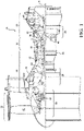
- FIG. 1 schematically illustrates a gas turbine engine 20.
- the gas turbine engine 20 is disclosed herein as a two-spool turbo fan that generally incorporates a fan section 22, a compressor section 24, a combustor section 26 and a turbine section 28.
- Alternative engine architectures might include an augmentor section among other systems or features.
- the fan section 22 drives air along a bypass flowpath and into the compressor section 24.
- the compressor section 24 drives air along a core flowpath for compression and communication into the combustor section 26, which then expands and directs the air through the turbine section 28.
- turbofan in the disclosed non-limiting embodiment, it should be appreciated that the concepts described herein are not limited to use with turbofans as the teachings may be applied to other types of turbine engines such as a turbojets, turboshafts, and three-spool (plus fan) turbofans wherein an intermediate spool includes an Intermediate Pressure Compressor ("IPC") between a Low Pressure Compressor (“LPC”) and a High Pressure Compressor (“HPC”), and an Intermediate Pressure Turbine (“IPT”) between the High Pressure Turbine (“HPT”) and the Low Pressure Turbine (“LPT”).
- IPC Intermediate Pressure Compressor
- LPC Low Pressure Compressor
- HPC High Pressure Compressor
- IPT Intermediate Pressure Turbine
- the engine 20 generally includes a low spool 30 and a high spool 32 mounted for rotation about an engine central longitudinal axis A relative to an engine static structure 36 via several bearing structures 38.
- the low spool 30 generally includes an inner shaft 40 that interconnects a fan 42, a Low Pressure Compressor (“LPC”) 44 and a Low Pressure Turbine (“LPT”) 46.
- the inner shaft 40 drives the fan 42 directly or through a geared architecture 48 to drive the fan 42 at a lower speed than the low spool 30.
- An exemplary reduction transmission is an epicyclic transmission, namely a planetary or star gear system.
- the high spool 32 includes an outer shaft 50 that interconnects a High Pressure Compressor ("HPC") 52 and High Pressure Turbine (“HPT”) 54.
- a combustor 56 is arranged between the HPC 52 and the HPT 54.
- the inner shaft 40 and the outer shaft 50 are concentric and rotate about the engine central longitudinal axis A which is collinear with their longitudinal axes.
- Core airflow is compressed by the LPC 44, then the HPC 52, mixed with the fuel and burned in the combustor 56, then expanded over the HPT 54 and the LPT 46.
- the LPT 46 and HPT 54 rotationally drive the respective low spool 30 and high spool 32 in response to the expansion.
- the main engine shafts 40, 50 are supported at a plurality of points by bearing systems 38 within the static structure 36.
- the gas turbine engine 20 is a high-bypass geared aircraft engine.
- the gas turbine engine 20 bypass ratio is greater than about six.
- the geared architecture 48 can include an epicyclic gear train, such as a planetary gear system or other gear system.
- the example epicyclic gear train has a gear reduction ratio of greater than about 2.3, and in another example is greater than about 2.5:1.
- the geared turbofan enables operation of the low spool 30 at higher speeds which can increase the operational efficiency of the LPC 44 and LPT 46 and render increased pressure in a fewer number of stages.
- a pressure ratio associated with the LPT 46 is pressure measured prior to the inlet of the LPT 46 as related to the pressure at the outlet of the LPT 46 prior to an exhaust nozzle of the gas turbine engine 20.
- the bypass ratio of the gas turbine engine 20 is greater than about ten
- the fan diameter is significantly larger than that of the LPC 44
- the LPT 46 has a pressure ratio that is greater than about five. It should be appreciated, however, that the above parameters are only exemplary of one embodiment of a geared architecture engine and that the present disclosure is applicable to other gas turbine engines including direct drive turbofans.
- a significant amount of thrust is provided by the bypass flow due to the high bypass ratio.
- the fan section 22 of the gas turbine engine 20 is designed for a particular flight condition - typically cruise at about 0.8 Mach and about 35,000 feet (10,668m). This flight condition, with the gas turbine engine 20 at its best fuel consumption, is also known as bucket cruise Thrust Specific Fuel Consumption (TSFC).
- TSFC Thrust Specific Fuel Consumption
- Fan Pressure Ratio is the pressure ratio across a blade of the fan section 22 without the use of a Fan Exit Guide Vane system.
- the low Fan Pressure Ratio according to one non-limiting embodiment of the example gas turbine engine 20 is less than 1.45.
- the Low Corrected Fan Tip Speed according to one non-limiting embodiment of the example gas turbine engine 20 is less than about 1150 fps (351 m/s).
- the combustor section 26 generally includes a combustor 56 with an outer combustor wall assembly 60, an inner combustor wall assembly 62, and a diffuser case module 64.
- the outer combustor wall assembly 60 and the inner combustor wall assembly 62 are spaced apart such that a combustion chamber 66 is defined therebetween.
- the combustion chamber 66 is generally annular in shape to surround the engine central longitudinal axis A.
- the outer combustor liner assembly 60 is spaced radially inward from an outer diffuser case 64A of the diffuser case module 64 to define an outer annular plenum 76.
- the inner combustor liner assembly 62 is spaced radially outward from an inner diffuser case 64B of the diffuser case module 64 to define an inner annular plenum 78. It should be appreciated that although a particular combustor is illustrated, other combustor types with various combustor liner arrangements will also benefit herefrom. It should be further appreciated that the disclosed cooling flow paths are but an illustrated embodiment and should not be limited only thereto.
- the combustor wall assemblies 60, 62 contain the combustion products for direction toward the turbine section 28.
- Each combustor wall assembly 60, 62 generally includes a respective support shell 68, 70 which supports one or more liner panels 72, 74 mounted thereto arranged to form a liner array.
- the support shells 68, 70 may be manufactured by, for example, the hydroforming of a sheet metal alloy to provide the generally cylindrical outer shell 68 and inner shell 70.
- Each of the liner panels 72, 74 may be generally rectilinear with a circumferential arc.
- the liner panels 72, 74 may be manufactured of, for example, a nickel based super alloy, ceramic or other temperature resistant material.
- the liner array includes a multiple of forward liner panels 72A and a multiple of aft liner panels 74A that are circumferentially staggered to line the outer shell 68.
- a multiple of forward liner panels 72B and a multiple of aft liner panels 74B are circumferentially staggered to line the inner shell 70.
- the combustor 56 further includes a forward assembly 80 immediately downstream of the compressor section 24 to receive compressed airflow therefrom.
- the forward assembly 80 generally includes a cowl 82, a bulkhead assembly 84, and a multiple of swirlers 90 (one shown). Each of the swirlers 90 is circumferentially aligned with one of a multiple of fuel nozzles 86 (one shown) and the respective hood ports 94 to project through the bulkhead assembly 84.
- the bulkhead assembly 84 includes a bulkhead support shell 96 secured to the combustor walls 60, 62, and a multiple of circumferentially distributed bulkhead liner panels 98 secured to the bulkhead support shell 96 around the swirler opening.
- the bulkhead support shell 96 is generally annular and the multiple of circumferentially distributed bulkhead liner panels 98 are segmented, typically one to each fuel nozzle 86 and swirler 90.
- the cowl 82 extends radially between, and is secured to, the forwardmost ends of the combustor walls 60, 62.
- the cowl 82 includes a multiple of circumferentially distributed hood ports 94 that receive one of the respective multiple of fuel nozzles 86 and facilitates the direction of compressed air into the forward end of the combustion chamber 66 through a swirler opening 92.
- Each fuel nozzle 86 may be secured to the diffuser case module 64 and project through one of the hood ports 94 and through the swirler opening 92 within the respective swirler 90.
- the forward assembly 80 introduces core combustion air into the forward section of the combustion chamber 66 while the remainder enters the outer annular plenum 76 and the inner annular plenum 78.
- the multiple of fuel nozzles 86 and adjacent structure generate a blended fuel-air mixture that supports stable combustion in the combustion chamber 66.
- the outer and inner support shells 68, 70 are mounted to a first row of Nozzle Guide Vanes (NGVs) 54A in the HPT 54.
- the NGVs 54A are static engine components which direct core airflow combustion gases onto the turbine blades of the first turbine rotor in the turbine section 28 to facilitate the conversion of pressure energy into kinetic energy.
- the core airflow combustion gases are also accelerated by the NGVs 54A because of their convergent shape and are typically given a "spin” or a "swirl” in the direction of turbine rotor rotation.
- the turbine rotor blades absorb this energy to drive the turbine rotor at high speed.
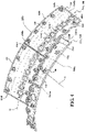
- a multiple of studs 100 extend from each of the liner panels 72, 74 so as to permit a liner array (partially shown in FIG. 4 ) of the liner panels 72, 74 to be mounted to their respective support shells 68, 70 with fasteners 102 such as nuts. That is, the studs 100 project rigidly from the liner panels 72, 74 to extend through the respective support shells 68, 70 and receive the fasteners 102 on a threaded section thereof ( FIG. 5 ).
- a multiple of cooling impingement passages 104 penetrate through the support shells 68, 70 to allow air from the respective annular plenums 76, 78 to enter cavities 106 formed in the combustor walls 60, 62 between the respective support shells 68, 70 and liner panels 72, 74.
- the impingement passages 104 are generally normal to the surface of the liner panels 72, 74.
- the air in the cavities 106 provides cold side impingement cooling of the liner panels 72, 74 that is generally defined herein as heat removal via internal convection.
- a multiple of effusion passages 108 penetrate through each of the liner panels 72, 74.
- the geometry of the passages e.g., diameter, shape, density, surface arcuate surface, incidence arcuate surface, etc., as well as the location of the passages with respect to the high temperature combustion flow also contributes to effusion cooling.
- the effusion passages 108 allow the air to pass from the cavities 106 defined in part by a cold side 110 of the liner panels 72, 74 to a hot side 112 of the liner panels 72, 74 and thereby facilitate the formation of a thin, relatively cool, film of cooling air along the hot side 112.
- each of the multiple of effusion passages 108 are typically 0.025" (0.635 mm) in diameter and define a surface arcuate surface section of about thirty (30) degrees with respect to the cold side 110 of the liner panels 72, 74.
- the effusion passages 108 are generally more numerous than the impingement passages 104 and promote film cooling along the hot side 112 to sheath the liner panels 72, 74 ( FIG. 6 ).
- Film cooling as defined herein is the introduction of a relatively cooler air at one or more discrete locations along a surface exposed to a high temperature environment to protect that surface in the region of the air injection as well as downstream thereof.
- impingement passages 104 and effusion passages 108 may be referred to as an Impingement Film Floatwall (IFF) assembly.
- IFF Impingement Film Floatwall
- a multiple of dilution passages 116 are located in the liner panels 72, 74 each along a common axis D.
- the dilution passages 116 are located in a circumferential line W (shown partially in FIG. 4 ).
- the dilution passages 116 are illustrated in the disclosed non-limiting embodiment as within the aft liner panels 74A, 74B, the dilution passages may alternatively be located in the forward liner panels 72A, 72B or in a single liner panel which replaces the fore/aft liner panel array.
- the dilution passages 116 although illustrated in the disclosed non-limiting embodiment as integrally formed in the liner panels, it should be appreciated that the dilution passages 116 may be separate components. Whether integrally formed or separate components, the dilution passages 116 may be referred to as grommets.
- each of the forward liner panels 72A, 72B, and the aft liner panels 74A, 74B in the liner panel array includes a perimeter rail 120a, 120b formed adjacent to a forward circumferential edge 122a, 122b, an aft circumferential edge 124a, 124b, and axial edges 126Aa 126Ab, 126Ba, 126Bb, that interconnect the forward and aft circumferential edge 122a, 122b, 124a, 124b.
- the perimeter rail 120a, 120b is located adjacent to the edge of the respective forward liner panels 72A, 72B, and the aft liner panels 74A, 74B to seal each liner panel with respect to the respective support shell 68, 70 to form the impingement cavity 106 therebetween. That is, the forward and aft circumferential edge 122a, 122b, 124a, 124b are located at relatively constant curvature shell interfaces while the axial edges 126Aa 126Ab, 126Ba, 126Bb, extend across an axial length of the respective support shell 68, 70.
- the perimeter rail 120a, 120b may be located adjacent to or form a portion of the forward circumferential edge 122a, 122b, the aft circumferential edge 124a, 124b, and the axial edges 126Aa 126Ab, 126Ba, 126Bb to seal the forward liner panels 72A, 72B, and the aft liner panels 74A, 74B to the respective support shell 68, 70.
- a multiple of studs 100 are located adjacent to the respective forward and aft circumferential edge 122a, 122b, 124a, 124b.
- Each of the studs 100 may be at least partially surrounded by posts 132 to at least partially support the fastener 102 and provide a stand-off between each forward liner panels 72A, 72B, and the aft liner panels 74A, 74B and respective support shell 68, 70.
- the dilution passages 116 are located downstream of the forward circumferential edge 122a, 122b in the aft liner panels 74A, 74B to quench the hot combustion gases within the combustion chamber 66 by direct supply of cooling air from the respective annular plenums 76, 78. That is, the dilution passages 116 pass air at the pressure outside the combustion chamber 66 directly into the combustion chamber 66.
- the dilution passages 116 include at least one set of circumferentially alternating major dilution passages 116A and minor dilution passages 116B (also shown in FIG. 6 ). That is, in some circumferentially offset locations, two major dilution passages 116A are separated by one minor dilution passages 116B. Here, every two major dilution passages 116A are separated by one minor dilution passages 116B but may still be considered "circumferentially alternating" as described herein.
- each of the major dilution passages 116A is about 0.5" (12.7 mm) in diameter and the total number of major dilution passages 116A communicates about eighty-five percent (85%) of the dilution airflow.
- the minor dilution passages 116B are each about 0.2" (5.1 mm) in diameter and the total number of minor dilution passages 116B communicates about fifteen percent (15%) of the dilution airflow. It should be appreciated that the dilution passages 116A, 116B need not be circular.
- the forward liner panels 72A, 72B include the non-linear aft circumferential edge 124a while the aft liner panels 74A, 74B includes the complementary non-linear forward circumferential edge 122b.
- "Complementary,” as defined herein, is that the non-linear aft circumferential edge 124a fits together with the non-linear forward circumferential edge 122b to form a non-linear interface 130.
- the non-linear interface 130 may be repeated over one or a multiple of adjacent forward and aft liner panels. Further, although illustrated between a forward and aft liner panel, the non-linear interface may be located between other arrays such as between liner and bulkhead panels.
- the non-linear aft circumferential edge 124a and the non-linear forward circumferential edge 122b are contoured with respect to each of the multiple of studs 100. That is, the non-linear aft circumferential edge 124a and the non-linear forward circumferential edge 122b are spaced a distance D1 from each of the multiple of studs 100. In one example, the distance D1 is 2.0X-10X where X is the diameter of the stud 100 ( FIG. 8 ).
- a stud of about 0.25 inches (6.35mm) results in the respective non-linear aft circumferential edge 124a and the non-linear forward circumferential edge 122b to be spaced about 0.5 - 2.5 inches (12.5 - 63.5 mm) from the stud 100.
- the non-linear aft circumferential edge 124a and the non-linear forward circumferential edge 122b are contoured with respect to each of the multiple of dilution passages 116. That is, the non-linear aft circumferential edge 124a and the non-linear forward circumferential edge 122b are spaced a distance D2 from each of the multiple of dilution passages 116. In one example, the distance D2 is 0.5X-2X where X is the diameter of the dilution passage 116 ( FIG. 10 ).
- a dilution passages 116 of about 0.5 inches (12.7 mm) results in the respective non-linear aft circumferential edge 124a and the non-linear forward circumferential edge 122b to be spaced about 0.25 - 1 inches (6.25 - 25 mm) from the dilution passage 116.
- the non-linear aft circumferential edge 124a and the non-linear forward circumferential edge 122b are contoured with respect to each of the multiple of dilution passages 116 as well as each of multiple of studs 100 which may result in a relatively complex forward and aft liner panel interface.
- the curved edged profiles can be cooled more effectively by providing space between panel features and in areas subject to high heat transfer.
- the curved edges are also readily employed in cast and machined panel designs and incorporated in dual wall liners and facilitates packaging and repair options for refurbishment of combustors.
- the non-linear forward and aft liner panel interface increases combustor durability and the ability to optimize the combustor design and performance.
- Combustor liners with a kink or bend can eliminate interfaces that result in steps, dead regions, cooling challenges and adverse local aerodynamics. Panels of this geometry edges are readily employed in cast and machined panel designs and incorporated in dual wall liners.
Landscapes
- Engineering & Computer Science (AREA)
- Mechanical Engineering (AREA)
- General Engineering & Computer Science (AREA)
- Chemical & Material Sciences (AREA)
- Combustion & Propulsion (AREA)
- Turbine Rotor Nozzle Sealing (AREA)
Claims (5)
- Brennkammer (56) für ein Gasturbinentriebwerk (20), umfassend:eine Stützschale (68,70);eine vordere Auskleidungsplatte (72A, 72B), die an der Stützschale (68, 70) über eine Vielzahl von Bolzen (100) montiert ist, wobei die vordere Auskleidungsplatte (72A, 72B) eine hintere nichtlineare Umfangskante (124a) beinhaltet; undeine hintere Auskleidungsplatte (74A, 74B), die an der Stützschale (68, 70) über eine Vielzahl von Bolzen (100) montiert ist, wobei die hintere Auskleidungsplatte (74A, 74B) eine vordere nichtlineare Umfangskante (122b) beinhaltet,wobei die Brennkammer (56) Hohlräume (106) zwischen der Stützschale (68, 70) und jeder von der vorderen und der hinteren Auskleidungsplatte (72A, 72B, 74A, 74B) umfasst,wobei die Stützschale (68, 70) Prallkanäle (104) umfasst, die konfiguriert sind, um zuzulassen, dass Kühlluft in die Hohlräume (106) eintritt, und um Prallkühlung einer kalten Seite (110) der vorderen und der hinteren Auskleidungsplatte (72A, 72B, 74A, 74B) bereitzustellen,dadurch gekennzeichnet, dass:die vordere nichtlineare Umfangskante (122b) der hinteren Auskleidungsplatte (74A, 74B) komplementär zu der hinteren nichtlinearen Umfangskante (124a) der vorderen Auskleidungsplatte (72A, 72B) ist;die vordere nichtlineare Umfangskante (122b) und die hintere nichtlineare Umfangskante (124a) eine nichtlineare Schnittstelle (130) bilden; unddie vordere und die hintere Auskleidungsplatte (72A, 72B, 74A, 74B) jeweils Effusionskanäle (108) umfassen, die konfiguriert sind, um zuzulassen, dass die Kühlluft von den Hohlräumen (106) zu einer heißen Seite (112) der jeweiligen vorderen und hinteren Auskleidungsplatte (72A, 72B, 74A, 74B) strömt.
- Brennkammer (56) nach Anspruch 1, wobei die vordere und die hintere nichtlineare Umfangskante (122b, 124a) in Bezug auf jeden aus einer Vielzahl von Bolzen (100) definiert sind.
- Brennkammer (56) nach Anspruch 2, wobei die nichtlinearen Umfangskanten (122b, 124a) um einen Abstand (D1) von jedem aus der Vielzahl von Bolzen (100) beabstandet sind und der Abstand (D1) 2,0X-10X ist, wobei X ein Durchmesser des Bolzens (100) ist.
- Brennkammer (56) nach einem vorhergehenden Anspruch, wobei die vordere und die hintere nichtlineare Umfangskante (122b, 124a) in Bezug auf jeden aus einer Vielzahl von Verdünnungskanälen (116) definiert sind.
- Brennkammer nach Anspruch 4, wobei die vordere und die hintere nichtlineare Umfangskante (122b, 124a) um einen Abstand (D2) von jedem aus der Vielzahl von Verdünnungskanälen (116) beabstandet sind und der Abstand (D2) 0,5X-2X ist, wobei X der Durchmesser des Verdünnungskanals (116) ist.
Applications Claiming Priority (1)
| Application Number | Priority Date | Filing Date | Title |
|---|---|---|---|
| US15/348,639 US10655853B2 (en) | 2016-11-10 | 2016-11-10 | Combustor liner panel with non-linear circumferential edge for a gas turbine engine combustor |
Publications (2)
| Publication Number | Publication Date |
|---|---|
| EP3321588A1 EP3321588A1 (de) | 2018-05-16 |
| EP3321588B1 true EP3321588B1 (de) | 2022-04-06 |
Family
ID=60327104
Family Applications (1)
| Application Number | Title | Priority Date | Filing Date |
|---|---|---|---|
| EP17201213.0A Active EP3321588B1 (de) | 2016-11-10 | 2017-11-10 | Gasturbinenbrennkammer |
Country Status (2)
| Country | Link |
|---|---|
| US (1) | US10655853B2 (de) |
| EP (1) | EP3321588B1 (de) |
Family Cites Families (71)
| Publication number | Priority date | Publication date | Assignee | Title |
|---|---|---|---|---|
| US4236378A (en) | 1978-03-01 | 1980-12-02 | General Electric Company | Sectoral combustor for burning low-BTU fuel gas |
| US4302941A (en) | 1980-04-02 | 1981-12-01 | United Technologies Corporation | Combuster liner construction for gas turbine engine |
| US4773227A (en) * | 1982-04-07 | 1988-09-27 | United Technologies Corporation | Combustion chamber with improved liner construction |
| EP0224817B1 (de) * | 1985-12-02 | 1989-07-12 | Siemens Aktiengesellschaft | Hitzeschildanordnung, insbesondere für Strukturteile von Gasturbinenanlagen |
| US5553455A (en) | 1987-12-21 | 1996-09-10 | United Technologies Corporation | Hybrid ceramic article |
| GB2267736B (en) | 1992-06-09 | 1995-08-09 | Gen Electric | Segmented turbine flowpath assembly |
| FR2752916B1 (fr) | 1996-09-05 | 1998-10-02 | Snecma | Chemise de protection thermique pour chambre de combustion de turboreacteur |
| WO1999047874A1 (de) | 1998-03-19 | 1999-09-23 | Siemens Aktiengesellschaft | Wandsegment für einen brennraum sowie brennraum |
| US6101814A (en) * | 1999-04-15 | 2000-08-15 | United Technologies Corporation | Low emissions can combustor with dilution hole arrangement for a turbine engine |
| DE10114619B4 (de) | 2000-03-27 | 2006-07-27 | Cummins Inc., Columbus | Belüftendes Befestigungselement |
| US6675582B2 (en) | 2001-05-23 | 2004-01-13 | General Electric Company | Slot cooled combustor line |
| US6568079B2 (en) | 2001-06-11 | 2003-05-27 | General Electric Company | Methods for replacing combustor liner panels |
| US6581285B2 (en) | 2001-06-11 | 2003-06-24 | General Electric Co. | Methods for replacing nuggeted combustor liner panels |
| GB0117110D0 (en) | 2001-07-13 | 2001-09-05 | Siemens Ag | Coolable segment for a turbomachinery and combustion turbine |
| US6655146B2 (en) | 2001-07-31 | 2003-12-02 | General Electric Company | Hybrid film cooled combustor liner |
| FR2840974B1 (fr) | 2002-06-13 | 2005-12-30 | Snecma Propulsion Solide | Anneau d'etancheite pour cahmbre de combustion et chambre de combustion comportant un tel anneau |
| EP1443275B1 (de) | 2003-01-29 | 2008-08-13 | Siemens Aktiengesellschaft | Brennkammer |
| US6931855B2 (en) | 2003-05-12 | 2005-08-23 | Siemens Westinghouse Power Corporation | Attachment system for coupling combustor liners to a carrier of a turbine combustor |
| EP1482246A1 (de) | 2003-05-30 | 2004-12-01 | Siemens Aktiengesellschaft | Brennkammer |
| US7363763B2 (en) | 2003-10-23 | 2008-04-29 | United Technologies Corporation | Combustor |
| US6868675B1 (en) | 2004-01-09 | 2005-03-22 | Honeywell International Inc. | Apparatus and method for controlling combustor liner carbon formation |
| EP1666797A1 (de) | 2004-12-01 | 2006-06-07 | Siemens Aktiengesellschaft | Hitzeschildelement, Verfahren zu dessen Herstellung, Heisgasauskleidung und Brennkammer |
| US8418470B2 (en) | 2005-10-07 | 2013-04-16 | United Technologies Corporation | Gas turbine combustor bulkhead panel |
| GB2432902B (en) | 2005-12-03 | 2011-01-12 | Alstom Technology Ltd | Gas turbine sub-assemblies |
| US7665307B2 (en) | 2005-12-22 | 2010-02-23 | United Technologies Corporation | Dual wall combustor liner |
| US20080003078A1 (en) | 2006-05-02 | 2008-01-03 | United Technologies Corporation | Fastener |
| US7524167B2 (en) | 2006-05-04 | 2009-04-28 | Siemens Energy, Inc. | Combustor spring clip seal system |
| EP1862740B1 (de) | 2006-05-31 | 2015-09-16 | Siemens Aktiengesellschaft | Brennkammerwand |
| US7895841B2 (en) * | 2006-07-14 | 2011-03-01 | General Electric Company | Method and apparatus to facilitate reducing NOx emissions in turbine engines |
| WO2008017551A2 (de) | 2006-08-07 | 2008-02-14 | Alstom Technology Ltd | Brennkammer einer verbrennungsanlage |
| US8141370B2 (en) | 2006-08-08 | 2012-03-27 | General Electric Company | Methods and apparatus for radially compliant component mounting |
| US7726131B2 (en) | 2006-12-19 | 2010-06-01 | Pratt & Whitney Canada Corp. | Floatwall dilution hole cooling |
| US8528339B2 (en) | 2007-04-05 | 2013-09-10 | Siemens Energy, Inc. | Stacked laminate gas turbine component |
| US8256223B2 (en) | 2007-10-16 | 2012-09-04 | United Technologies Corporation | Ceramic combustor liner panel for a gas turbine engine |
| GB0801839D0 (en) | 2008-02-01 | 2008-03-05 | Rolls Royce Plc | combustion apparatus |
| MY158901A (en) | 2008-02-20 | 2016-11-30 | General Electric Technology Gmbh | Gas turbine having an annular combustion chamber |
| US8522560B2 (en) | 2009-03-25 | 2013-09-03 | United Technologies Corporation | Fuel-cooled heat exchanger with thermoelectric device compression |
| US8015817B2 (en) | 2009-06-10 | 2011-09-13 | Siemens Energy, Inc. | Cooling structure for gas turbine transition duct |
| GB0913580D0 (en) | 2009-08-05 | 2009-09-16 | Rolls Royce Plc | Combustor tile |
| US8359865B2 (en) | 2010-02-04 | 2013-01-29 | United Technologies Corporation | Combustor liner segment seal member |
| US8359866B2 (en) | 2010-02-04 | 2013-01-29 | United Technologies Corporation | Combustor liner segment seal member |
| US8608443B2 (en) * | 2010-06-11 | 2013-12-17 | Siemens Energy, Inc. | Film cooled component wall in a turbine engine |
| EP2463582B1 (de) | 2010-12-10 | 2019-06-19 | Rolls-Royce plc | Brennkammer |
| US8720204B2 (en) | 2011-02-09 | 2014-05-13 | Siemens Energy, Inc. | Resonator system with enhanced combustor liner cooling |
| JP5696566B2 (ja) | 2011-03-31 | 2015-04-08 | 株式会社Ihi | ガスタービンエンジン用燃焼器及びガスタービンエンジン |
| US8727714B2 (en) | 2011-04-27 | 2014-05-20 | Siemens Energy, Inc. | Method of forming a multi-panel outer wall of a component for use in a gas turbine engine |
| US9534783B2 (en) | 2011-07-21 | 2017-01-03 | United Technologies Corporation | Insert adjacent to a heat shield element for a gas turbine engine combustor |
| US8745988B2 (en) | 2011-09-06 | 2014-06-10 | Pratt & Whitney Canada Corp. | Pin fin arrangement for heat shield of gas turbine engine |
| US8839627B2 (en) | 2012-01-31 | 2014-09-23 | United Technologies Corporation | Annular combustor |
| EP2679780B8 (de) | 2012-06-28 | 2016-09-14 | General Electric Technology GmbH | Diffusor für den Abgasabschnitt einer Gasturbine, und Gasturbine mit einem solchen Diffusor |
| US9482432B2 (en) | 2012-09-26 | 2016-11-01 | United Technologies Corporation | Gas turbine engine combustor with integrated combustor vane having swirler |
| US9243515B2 (en) | 2012-09-28 | 2016-01-26 | United Technologies Corporation | Support hanger for flexibly connecting a plurality of panels |
| US9249732B2 (en) | 2012-09-28 | 2016-02-02 | United Technologies Corporation | Panel support hanger for a turbine engine |
| US10107497B2 (en) | 2012-10-04 | 2018-10-23 | United Technologies Corporation | Gas turbine engine combustor liner |
| EP2946092B1 (de) | 2013-01-17 | 2019-04-17 | United Technologies Corporation | Auskleidungsanordnung für gasturbinenbrennkammer mit konvergierendem hyperbolischem profil |
| WO2014149108A1 (en) | 2013-03-15 | 2014-09-25 | Graves Charles B | Shell and tiled liner arrangement for a combustor |
| US10634351B2 (en) | 2013-04-12 | 2020-04-28 | United Technologies Corporation | Combustor panel T-junction cooling |
| CN105324611A (zh) * | 2013-05-21 | 2016-02-10 | 西门子股份公司 | 用于燃烧室的隔热件的隔热瓦 |
| US8984896B2 (en) | 2013-08-23 | 2015-03-24 | Pratt & Whitney Canada Corp. | Interlocking combustor heat shield panels |
| GB201315871D0 (en) | 2013-09-06 | 2013-10-23 | Rolls Royce Plc | A combustion chamber arrangement |
| US10317080B2 (en) | 2013-12-06 | 2019-06-11 | United Technologies Corporation | Co-swirl orientation of combustor effusion passages for gas turbine engine combustor |
| US9410702B2 (en) | 2014-02-10 | 2016-08-09 | Honeywell International Inc. | Gas turbine engine combustors with effusion and impingement cooling and methods for manufacturing the same using additive manufacturing techniques |
| DE102014204476A1 (de) | 2014-03-11 | 2015-10-01 | Rolls-Royce Deutschland Ltd & Co Kg | Brennkammer einer Gasturbine |
| DE102014204481A1 (de) | 2014-03-11 | 2015-09-17 | Rolls-Royce Deutschland Ltd & Co Kg | Brennkammer einer Gasturbine |
| DE102014204482A1 (de) * | 2014-03-11 | 2015-09-17 | Rolls-Royce Deutschland Ltd & Co Kg | Brennkammer einer Gasturbine |
| US9557060B2 (en) | 2014-06-16 | 2017-01-31 | Pratt & Whitney Canada Corp. | Combustor heat shield |
| EP3040617B1 (de) | 2014-12-31 | 2017-12-06 | Rolls-Royce North American Technologies, Inc. | Haltesystem für teile einer gasturbine |
| GB201501817D0 (en) * | 2015-02-04 | 2015-03-18 | Rolls Royce Plc | A combustion chamber and a combustion chamber segment |
| DE102015205975A1 (de) | 2015-04-02 | 2016-10-06 | Siemens Aktiengesellschaft | Umführungs-Hitzeschildelement |
| GB201603166D0 (en) | 2016-02-24 | 2016-04-06 | Rolls Royce Plc | A combustion chamber |
| US10684014B2 (en) | 2016-08-04 | 2020-06-16 | Raytheon Technologies Corporation | Combustor panel for gas turbine engine |
-
2016
- 2016-11-10 US US15/348,639 patent/US10655853B2/en active Active
-
2017
- 2017-11-10 EP EP17201213.0A patent/EP3321588B1/de active Active
Non-Patent Citations (1)
| Title |
|---|
| None * |
Also Published As
| Publication number | Publication date |
|---|---|
| US20180231250A1 (en) | 2018-08-16 |
| US10655853B2 (en) | 2020-05-19 |
| EP3321588A1 (de) | 2018-05-16 |
Similar Documents
| Publication | Publication Date | Title |
|---|---|---|
| EP3366995B1 (de) | Anordnung von brennkammerauskleidungsplatten und verfahren zu deren kühlung | |
| EP3366996B1 (de) | Brennkammerauskleidungplattenendschienen welche eine abgewinkelte kühlpassage bilden für eine gasturbinenbrennkammer | |
| EP3366998B1 (de) | Brennkammer mit endschienen aus auskleidungspaneelen mit gekrümmter übergangspassage für ein gasturbinentriebwerk | |
| EP3415819B1 (de) | Brennkammer für ein gastirbinenmotor umfassend auskleidungsplatten mit diffundiertem schnittstellendurchgang | |
| EP3366997B1 (de) | Merkmale zur kühlungsverbesserung von endschienen von brennkammerauskleidungsplatten für eine gasturbinenbrennkammer | |
| EP3361158B1 (de) | Brennkammer für eine gasturbine | |
| EP3330611B1 (de) | Reguliertes brennkammerwandpaneel für gasturbinenmotorbrennkammer | |
| EP3321587B1 (de) | Axiale nichtlineare kontaktfläche für brennkammerverkleidungsplatten in einer gasturbinenbrennkammer | |
| EP3084307B1 (de) | Verdünnungsdurchgangsanordnung für eine gasturbinenbrennkammer | |
| EP3321585B1 (de) | Nichtplanare brennkammerverkleidungsplatte für eine gasturbinenmotorbrennkammer | |
| EP3321584B1 (de) | Gasturbinenmotorbrennkammer mit einer axial-nichtplanaren brennkammerverkleidungsplatte | |
| EP3318803B1 (de) | Bolzenanordnung für gasturbinenbrennkammer | |
| EP3321588B1 (de) | Gasturbinenbrennkammer | |
| EP3315862B1 (de) | Gegossene brennkammerauskleidungsplatte mit radiuskante für gasturbinenbrennkammer |
Legal Events
| Date | Code | Title | Description |
|---|---|---|---|
| PUAI | Public reference made under article 153(3) epc to a published international application that has entered the european phase |
Free format text: ORIGINAL CODE: 0009012 |
|
| STAA | Information on the status of an ep patent application or granted ep patent |
Free format text: STATUS: THE APPLICATION HAS BEEN PUBLISHED |
|
| AK | Designated contracting states |
Kind code of ref document: A1 Designated state(s): AL AT BE BG CH CY CZ DE DK EE ES FI FR GB GR HR HU IE IS IT LI LT LU LV MC MK MT NL NO PL PT RO RS SE SI SK SM TR |
|
| AX | Request for extension of the european patent |
Extension state: BA ME |
|
| STAA | Information on the status of an ep patent application or granted ep patent |
Free format text: STATUS: REQUEST FOR EXAMINATION WAS MADE |
|
| 17P | Request for examination filed |
Effective date: 20181115 |
|
| RBV | Designated contracting states (corrected) |
Designated state(s): AL AT BE BG CH CY CZ DE DK EE ES FI FR GB GR HR HU IE IS IT LI LT LU LV MC MK MT NL NO PL PT RO RS SE SI SK SM TR |
|
| STAA | Information on the status of an ep patent application or granted ep patent |
Free format text: STATUS: EXAMINATION IS IN PROGRESS |
|
| 17Q | First examination report despatched |
Effective date: 20200421 |
|
| RAP1 | Party data changed (applicant data changed or rights of an application transferred) |
Owner name: RAYTHEON TECHNOLOGIES CORPORATION |
|
| GRAP | Despatch of communication of intention to grant a patent |
Free format text: ORIGINAL CODE: EPIDOSNIGR1 |
|
| STAA | Information on the status of an ep patent application or granted ep patent |
Free format text: STATUS: GRANT OF PATENT IS INTENDED |
|
| INTG | Intention to grant announced |
Effective date: 20211020 |
|
| GRAS | Grant fee paid |
Free format text: ORIGINAL CODE: EPIDOSNIGR3 |
|
| GRAA | (expected) grant |
Free format text: ORIGINAL CODE: 0009210 |
|
| STAA | Information on the status of an ep patent application or granted ep patent |
Free format text: STATUS: THE PATENT HAS BEEN GRANTED |
|
| AK | Designated contracting states |
Kind code of ref document: B1 Designated state(s): AL AT BE BG CH CY CZ DE DK EE ES FI FR GB GR HR HU IE IS IT LI LT LU LV MC MK MT NL NO PL PT RO RS SE SI SK SM TR |
|
| REG | Reference to a national code |
Ref country code: GB Ref legal event code: FG4D |
|
| REG | Reference to a national code |
Ref country code: CH Ref legal event code: EP |
|
| REG | Reference to a national code |
Ref country code: AT Ref legal event code: REF Ref document number: 1481671 Country of ref document: AT Kind code of ref document: T Effective date: 20220415 |
|
| REG | Reference to a national code |
Ref country code: DE Ref legal event code: R096 Ref document number: 602017055472 Country of ref document: DE |
|
| REG | Reference to a national code |
Ref country code: IE Ref legal event code: FG4D |
|
| REG | Reference to a national code |
Ref country code: LT Ref legal event code: MG9D |
|
| REG | Reference to a national code |
Ref country code: NL Ref legal event code: MP Effective date: 20220406 |
|
| REG | Reference to a national code |
Ref country code: AT Ref legal event code: MK05 Ref document number: 1481671 Country of ref document: AT Kind code of ref document: T Effective date: 20220406 |
|
| PG25 | Lapsed in a contracting state [announced via postgrant information from national office to epo] |
Ref country code: NL Free format text: LAPSE BECAUSE OF FAILURE TO SUBMIT A TRANSLATION OF THE DESCRIPTION OR TO PAY THE FEE WITHIN THE PRESCRIBED TIME-LIMIT Effective date: 20220406 |
|
| PG25 | Lapsed in a contracting state [announced via postgrant information from national office to epo] |
Ref country code: SE Free format text: LAPSE BECAUSE OF FAILURE TO SUBMIT A TRANSLATION OF THE DESCRIPTION OR TO PAY THE FEE WITHIN THE PRESCRIBED TIME-LIMIT Effective date: 20220406 Ref country code: PT Free format text: LAPSE BECAUSE OF FAILURE TO SUBMIT A TRANSLATION OF THE DESCRIPTION OR TO PAY THE FEE WITHIN THE PRESCRIBED TIME-LIMIT Effective date: 20220808 Ref country code: NO Free format text: LAPSE BECAUSE OF FAILURE TO SUBMIT A TRANSLATION OF THE DESCRIPTION OR TO PAY THE FEE WITHIN THE PRESCRIBED TIME-LIMIT Effective date: 20220706 Ref country code: LT Free format text: LAPSE BECAUSE OF FAILURE TO SUBMIT A TRANSLATION OF THE DESCRIPTION OR TO PAY THE FEE WITHIN THE PRESCRIBED TIME-LIMIT Effective date: 20220406 Ref country code: HR Free format text: LAPSE BECAUSE OF FAILURE TO SUBMIT A TRANSLATION OF THE DESCRIPTION OR TO PAY THE FEE WITHIN THE PRESCRIBED TIME-LIMIT Effective date: 20220406 Ref country code: GR Free format text: LAPSE BECAUSE OF FAILURE TO SUBMIT A TRANSLATION OF THE DESCRIPTION OR TO PAY THE FEE WITHIN THE PRESCRIBED TIME-LIMIT Effective date: 20220707 Ref country code: FI Free format text: LAPSE BECAUSE OF FAILURE TO SUBMIT A TRANSLATION OF THE DESCRIPTION OR TO PAY THE FEE WITHIN THE PRESCRIBED TIME-LIMIT Effective date: 20220406 Ref country code: ES Free format text: LAPSE BECAUSE OF FAILURE TO SUBMIT A TRANSLATION OF THE DESCRIPTION OR TO PAY THE FEE WITHIN THE PRESCRIBED TIME-LIMIT Effective date: 20220406 Ref country code: BG Free format text: LAPSE BECAUSE OF FAILURE TO SUBMIT A TRANSLATION OF THE DESCRIPTION OR TO PAY THE FEE WITHIN THE PRESCRIBED TIME-LIMIT Effective date: 20220706 Ref country code: AT Free format text: LAPSE BECAUSE OF FAILURE TO SUBMIT A TRANSLATION OF THE DESCRIPTION OR TO PAY THE FEE WITHIN THE PRESCRIBED TIME-LIMIT Effective date: 20220406 |
|
| PG25 | Lapsed in a contracting state [announced via postgrant information from national office to epo] |
Ref country code: RS Free format text: LAPSE BECAUSE OF FAILURE TO SUBMIT A TRANSLATION OF THE DESCRIPTION OR TO PAY THE FEE WITHIN THE PRESCRIBED TIME-LIMIT Effective date: 20220406 Ref country code: PL Free format text: LAPSE BECAUSE OF FAILURE TO SUBMIT A TRANSLATION OF THE DESCRIPTION OR TO PAY THE FEE WITHIN THE PRESCRIBED TIME-LIMIT Effective date: 20220406 Ref country code: LV Free format text: LAPSE BECAUSE OF FAILURE TO SUBMIT A TRANSLATION OF THE DESCRIPTION OR TO PAY THE FEE WITHIN THE PRESCRIBED TIME-LIMIT Effective date: 20220406 Ref country code: IS Free format text: LAPSE BECAUSE OF FAILURE TO SUBMIT A TRANSLATION OF THE DESCRIPTION OR TO PAY THE FEE WITHIN THE PRESCRIBED TIME-LIMIT Effective date: 20220806 |
|
| REG | Reference to a national code |
Ref country code: DE Ref legal event code: R097 Ref document number: 602017055472 Country of ref document: DE |
|
| PG25 | Lapsed in a contracting state [announced via postgrant information from national office to epo] |
Ref country code: SM Free format text: LAPSE BECAUSE OF FAILURE TO SUBMIT A TRANSLATION OF THE DESCRIPTION OR TO PAY THE FEE WITHIN THE PRESCRIBED TIME-LIMIT Effective date: 20220406 Ref country code: SK Free format text: LAPSE BECAUSE OF FAILURE TO SUBMIT A TRANSLATION OF THE DESCRIPTION OR TO PAY THE FEE WITHIN THE PRESCRIBED TIME-LIMIT Effective date: 20220406 Ref country code: RO Free format text: LAPSE BECAUSE OF FAILURE TO SUBMIT A TRANSLATION OF THE DESCRIPTION OR TO PAY THE FEE WITHIN THE PRESCRIBED TIME-LIMIT Effective date: 20220406 Ref country code: EE Free format text: LAPSE BECAUSE OF FAILURE TO SUBMIT A TRANSLATION OF THE DESCRIPTION OR TO PAY THE FEE WITHIN THE PRESCRIBED TIME-LIMIT Effective date: 20220406 Ref country code: DK Free format text: LAPSE BECAUSE OF FAILURE TO SUBMIT A TRANSLATION OF THE DESCRIPTION OR TO PAY THE FEE WITHIN THE PRESCRIBED TIME-LIMIT Effective date: 20220406 Ref country code: CZ Free format text: LAPSE BECAUSE OF FAILURE TO SUBMIT A TRANSLATION OF THE DESCRIPTION OR TO PAY THE FEE WITHIN THE PRESCRIBED TIME-LIMIT Effective date: 20220406 |
|
| PLBE | No opposition filed within time limit |
Free format text: ORIGINAL CODE: 0009261 |
|
| STAA | Information on the status of an ep patent application or granted ep patent |
Free format text: STATUS: NO OPPOSITION FILED WITHIN TIME LIMIT |
|
| 26N | No opposition filed |
Effective date: 20230110 |
|
| PG25 | Lapsed in a contracting state [announced via postgrant information from national office to epo] |
Ref country code: AL Free format text: LAPSE BECAUSE OF FAILURE TO SUBMIT A TRANSLATION OF THE DESCRIPTION OR TO PAY THE FEE WITHIN THE PRESCRIBED TIME-LIMIT Effective date: 20220406 |
|
| PG25 | Lapsed in a contracting state [announced via postgrant information from national office to epo] |
Ref country code: SI Free format text: LAPSE BECAUSE OF FAILURE TO SUBMIT A TRANSLATION OF THE DESCRIPTION OR TO PAY THE FEE WITHIN THE PRESCRIBED TIME-LIMIT Effective date: 20220406 |
|
| P01 | Opt-out of the competence of the unified patent court (upc) registered |
Effective date: 20230520 |
|
| PG25 | Lapsed in a contracting state [announced via postgrant information from national office to epo] |
Ref country code: MC Free format text: LAPSE BECAUSE OF FAILURE TO SUBMIT A TRANSLATION OF THE DESCRIPTION OR TO PAY THE FEE WITHIN THE PRESCRIBED TIME-LIMIT Effective date: 20220406 |
|
| REG | Reference to a national code |
Ref country code: CH Ref legal event code: PL |
|
| REG | Reference to a national code |
Ref country code: BE Ref legal event code: MM Effective date: 20221130 |
|
| PG25 | Lapsed in a contracting state [announced via postgrant information from national office to epo] |
Ref country code: LI Free format text: LAPSE BECAUSE OF NON-PAYMENT OF DUE FEES Effective date: 20221130 Ref country code: CH Free format text: LAPSE BECAUSE OF NON-PAYMENT OF DUE FEES Effective date: 20221130 |
|
| PG25 | Lapsed in a contracting state [announced via postgrant information from national office to epo] |
Ref country code: LU Free format text: LAPSE BECAUSE OF NON-PAYMENT OF DUE FEES Effective date: 20221110 |
|
| PG25 | Lapsed in a contracting state [announced via postgrant information from national office to epo] |
Ref country code: IE Free format text: LAPSE BECAUSE OF NON-PAYMENT OF DUE FEES Effective date: 20221110 |
|
| PG25 | Lapsed in a contracting state [announced via postgrant information from national office to epo] |
Ref country code: BE Free format text: LAPSE BECAUSE OF NON-PAYMENT OF DUE FEES Effective date: 20221130 |
|
| PG25 | Lapsed in a contracting state [announced via postgrant information from national office to epo] |
Ref country code: IT Free format text: LAPSE BECAUSE OF FAILURE TO SUBMIT A TRANSLATION OF THE DESCRIPTION OR TO PAY THE FEE WITHIN THE PRESCRIBED TIME-LIMIT Effective date: 20220406 |
|
| PG25 | Lapsed in a contracting state [announced via postgrant information from national office to epo] |
Ref country code: HU Free format text: LAPSE BECAUSE OF FAILURE TO SUBMIT A TRANSLATION OF THE DESCRIPTION OR TO PAY THE FEE WITHIN THE PRESCRIBED TIME-LIMIT; INVALID AB INITIO Effective date: 20171110 |
|
| PG25 | Lapsed in a contracting state [announced via postgrant information from national office to epo] |
Ref country code: CY Free format text: LAPSE BECAUSE OF FAILURE TO SUBMIT A TRANSLATION OF THE DESCRIPTION OR TO PAY THE FEE WITHIN THE PRESCRIBED TIME-LIMIT Effective date: 20220406 |
|
| PG25 | Lapsed in a contracting state [announced via postgrant information from national office to epo] |
Ref country code: MK Free format text: LAPSE BECAUSE OF FAILURE TO SUBMIT A TRANSLATION OF THE DESCRIPTION OR TO PAY THE FEE WITHIN THE PRESCRIBED TIME-LIMIT Effective date: 20220406 |
|
| PG25 | Lapsed in a contracting state [announced via postgrant information from national office to epo] |
Ref country code: MT Free format text: LAPSE BECAUSE OF FAILURE TO SUBMIT A TRANSLATION OF THE DESCRIPTION OR TO PAY THE FEE WITHIN THE PRESCRIBED TIME-LIMIT Effective date: 20220406 |
|
| PG25 | Lapsed in a contracting state [announced via postgrant information from national office to epo] |
Ref country code: BG Free format text: LAPSE BECAUSE OF FAILURE TO SUBMIT A TRANSLATION OF THE DESCRIPTION OR TO PAY THE FEE WITHIN THE PRESCRIBED TIME-LIMIT Effective date: 20220406 |
|
| PG25 | Lapsed in a contracting state [announced via postgrant information from national office to epo] |
Ref country code: BG Free format text: LAPSE BECAUSE OF FAILURE TO SUBMIT A TRANSLATION OF THE DESCRIPTION OR TO PAY THE FEE WITHIN THE PRESCRIBED TIME-LIMIT Effective date: 20220406 |
|
| REG | Reference to a national code |
Ref country code: DE Ref legal event code: R081 Ref document number: 602017055472 Country of ref document: DE Owner name: RTX CORPORATION (N.D.GES.D. STAATES DELAWARE),, US Free format text: FORMER OWNER: RAYTHEON TECHNOLOGIES CORPORATION, FARMINGTON, CT, US |
|
| PG25 | Lapsed in a contracting state [announced via postgrant information from national office to epo] |
Ref country code: TR Free format text: LAPSE BECAUSE OF FAILURE TO SUBMIT A TRANSLATION OF THE DESCRIPTION OR TO PAY THE FEE WITHIN THE PRESCRIBED TIME-LIMIT Effective date: 20220406 |
|
| PGFP | Annual fee paid to national office [announced via postgrant information from national office to epo] |
Ref country code: DE Payment date: 20251022 Year of fee payment: 9 |
|
| PGFP | Annual fee paid to national office [announced via postgrant information from national office to epo] |
Ref country code: GB Payment date: 20251022 Year of fee payment: 9 |
|
| PGFP | Annual fee paid to national office [announced via postgrant information from national office to epo] |
Ref country code: FR Payment date: 20251022 Year of fee payment: 9 |