EP3321901A1 - Système de sécurité périmétrique à fibre optique répartie, et système et procédé de restitution sonore - Google Patents
Système de sécurité périmétrique à fibre optique répartie, et système et procédé de restitution sonore Download PDFInfo
- Publication number
- EP3321901A1 EP3321901A1 EP16840733.6A EP16840733A EP3321901A1 EP 3321901 A1 EP3321901 A1 EP 3321901A1 EP 16840733 A EP16840733 A EP 16840733A EP 3321901 A1 EP3321901 A1 EP 3321901A1
- Authority
- EP
- European Patent Office
- Prior art keywords
- optical fiber
- signal
- sensing
- interference
- sound
- Prior art date
- Legal status (The legal status is an assumption and is not a legal conclusion. Google has not performed a legal analysis and makes no representation as to the accuracy of the status listed.)
- Granted
Links
Images

Classifications
-
- G—PHYSICS
- G01—MEASURING; TESTING
- G01H—MEASUREMENT OF MECHANICAL VIBRATIONS OR ULTRASONIC, SONIC OR INFRASONIC WAVES
- G01H9/00—Measuring mechanical vibrations or ultrasonic, sonic or infrasonic waves by using radiation-sensitive means, e.g. optical means
- G01H9/004—Measuring mechanical vibrations or ultrasonic, sonic or infrasonic waves by using radiation-sensitive means, e.g. optical means using fibre optic sensors
-
- G—PHYSICS
- G08—SIGNALLING
- G08B—SIGNALLING SYSTEMS, e.g. PERSONAL CALLING SYSTEMS; ORDER TELEGRAPHS; ALARM SYSTEMS
- G08B13/00—Burglar, theft or intruder alarms
-
- G—PHYSICS
- G08—SIGNALLING
- G08B—SIGNALLING SYSTEMS, e.g. PERSONAL CALLING SYSTEMS; ORDER TELEGRAPHS; ALARM SYSTEMS
- G08B13/00—Burglar, theft or intruder alarms
- G08B13/02—Mechanical actuation
- G08B13/12—Mechanical actuation by the breaking or disturbance of stretched cords or wires
- G08B13/122—Mechanical actuation by the breaking or disturbance of stretched cords or wires for a perimeter fence
- G08B13/124—Mechanical actuation by the breaking or disturbance of stretched cords or wires for a perimeter fence with the breaking or disturbance being optically detected, e.g. optical fibers in the perimeter fence
-
- G—PHYSICS
- G08—SIGNALLING
- G08B—SIGNALLING SYSTEMS, e.g. PERSONAL CALLING SYSTEMS; ORDER TELEGRAPHS; ALARM SYSTEMS
- G08B13/00—Burglar, theft or intruder alarms
- G08B13/16—Actuation by interference with mechanical vibrations in air or other fluid
- G08B13/1654—Actuation by interference with mechanical vibrations in air or other fluid using passive vibration detection systems
- G08B13/1672—Actuation by interference with mechanical vibrations in air or other fluid using passive vibration detection systems using sonic detecting means, e.g. a microphone operating in the audio frequency range
-
- G—PHYSICS
- G08—SIGNALLING
- G08B—SIGNALLING SYSTEMS, e.g. PERSONAL CALLING SYSTEMS; ORDER TELEGRAPHS; ALARM SYSTEMS
- G08B13/00—Burglar, theft or intruder alarms
- G08B13/18—Actuation by interference with heat, light, or radiation of shorter wavelength; Actuation by intruding sources of heat, light, or radiation of shorter wavelength
- G08B13/181—Actuation by interference with heat, light, or radiation of shorter wavelength; Actuation by intruding sources of heat, light, or radiation of shorter wavelength using active radiation detection systems
- G08B13/183—Actuation by interference with heat, light, or radiation of shorter wavelength; Actuation by intruding sources of heat, light, or radiation of shorter wavelength using active radiation detection systems by interruption of a radiation beam or barrier
- G08B13/186—Actuation by interference with heat, light, or radiation of shorter wavelength; Actuation by intruding sources of heat, light, or radiation of shorter wavelength using active radiation detection systems by interruption of a radiation beam or barrier using light guides, e.g. optical fibres
Definitions
- the present disclosure relates to the field of security technologies, and in particular, relates to a sound restoration system, a sound restoration method, and a distributed optical fiber perimeter security system.
- Optical fibers are not merely used to transmit signals, and are also used as sensors when being employed to sensing applications.
- ambient interference is propagated to the optical fibers, features or properties of optical signals transmitted over the optical fibers will be partially changed.
- a dedicated sensing instrument is configured to be capable of monitoring interference causing variations of the features or properties of the optical signals such as attenuation, phase, wavelength, polarization, mode field distribution and propagation time. By means of modulation of the optical signals, measurements of various events and states become possible.
- a distributed optical fiber perimeter security system is a distributed sensing system that uses the optical fiber as a sensing and transmission medium. Within a region in which the sensing optical fibers are arranged, the optical fiber perimeter security system is capable of monitoring, remotely and in real time, sudden events such as intrusion behaviors in a specific precision range.
- the optical fiber perimeter security system may be applied to perimeter security supervision in prisons, important military targets, arsenals, railings along railways and the like, and may also be applied to perimeter security supervision in residential blocks, government organs, nuclear power plants, airports and the like important facilities.
- a conventional distributed optical fiber perimeter security system divides the perimeter into several small monitoring areas (which are also referred to as protection areas), and each protection area is monitored by one optical fiber sensing unit.
- This optical fiber sensing unit generally has no positioning capability, and is only capable of sensing and transmitting intrusion vibration signals and judging whether an intrusion event occurs.
- a plurality of optical fiber sensing units construct a network, such that it may judge an intrusion event occurs in which protection area, thereby achieving the objective of positioning.
- the present disclosure is intended to provide a sound restoration system having a sound restoration capability, a sound restoration method, and a distributed optical fiber perimeter security system, so as to overcome, at least to some extent, one or more problems caused by restrictions and defects in the related arts.
- a sound restoration system which is applied to a distributed optical fiber perimeter security system which monitors several protection areas.
- the sound restoration system includes:
- the audio output mechanism is configured to restore the audio signal based on a light intensity of the interference signal.
- the optical fiber Michelson interference mechanism includes:
- I a light intensity of the interference signal
- I 1 and I 2 respectively represent light intensities of the optical signals in the reference arm and the sensing arm and ⁇ ⁇ ⁇ represents a phase difference therebetween
- n represents an effective refractive index of the sensing optical fiber
- ⁇ represents an incident wavelength of the input optical signal
- P 12 and P 11 represent Pockel constants
- v represents a Poisson's ratio
- ⁇ 3 represents an axial length variation rate of the sensing arm
- L represents a vibration length
- k represents an inherent parameter of the sensing optical fiber
- p represents a sound pressure when the sound signal is applied to the sensing arm.
- the front-end device includes an optical fiber coupler.
- the rear-end device includes a Faraday rotator mirror or a reflective mirror.
- the sensing optical fiber is configured to at least partially multiplex an intrusion-sensing optical fiber in the distributed optical fiber perimeter security system.
- the sensing optical fiber is arranged in a mesh shape, a spiral shape or a straight line shape.
- the audio output mechanism includes:
- the audio output mechanism further includes: a demodulation unit, configured to demodulate the audio signal to play and/or store a sound corresponding to the audio signal.
- a distributed optical fiber perimeter security system includes:
- the intrusion sensing system includes an optical fiber configured to sense and transmit the intrusion vibration signals, a sensing optical fiber of the optical fiber Michelson interference mechanism at least partially multiplexing the optical fiber.
- a sound restoration method which is applied to a distributed optical fiber perimeter security system which monitors several protection areas.
- the sound restoration method includes:
- the audio signal is restored based on a light intensity of the interference signal.
- I a light intensity of the interference signal
- the optical fiber Michelson interference mechanism includes a sensing optical fiber having a reference arm and a sensing arm
- I 1 and I 2 respectively represent light intensities of the optical signals in the reference arm and the sensing arm and ⁇ ⁇ represents a phase difference therebetween
- n represents an effective refractive index of the sensing optical fiber
- ⁇ represents an incident wavelength of the input optical signal
- P 12 and P 11 represent Pockel constants
- v a Poisson's ratio
- ⁇ 3 represents an axial length variation rate of the sensing arm
- L represents a vibration length
- k an inherent parameter of the sensing optical fiber
- p represents a
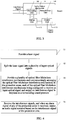
- interference signals generated based on the sound pressures of audio signals of a plurality of protection areas are acquired, and when an alarm signal of any of the protection areas is received, an audio signal restored based on the interference signal of the protection area is output.
- the sound restoration system outputs the corresponding audio signal only when the alarm signal is received, which in one aspect prevents interference caused to user's judgment and in another aspect saves system resources.
- this exemplary embodiment firstly provides a sound restoration system.
- the sound restoration system is applied to the distributed optical fiber perimeter security system which monitors a plurality of protection areas.
- the distributed optical fiber perimeter security system is capable of monitoring eight protection areas, and the sound restoration system may mainly include a laser generation mechanism 11, a beam splitting mechanism 12, a plurality of optical fiber Michelson interference mechanisms 13, and an audio output mechanism 14.
- the sound restoration system may mainly include a laser generation mechanism 11, a beam splitting mechanism 12, a plurality of optical fiber Michelson interference mechanisms 13, and an audio output mechanism 14.
- a person skilled in the art would also configure other structures such as a power supply, a control component, a signal optimization component and the like according to actual needs.
- the laser generation mechanism 11 is mainly configured to provide a laser signal.
- the laser generation mechanism 11 is preferably a semiconductor distributed feedback laser (DFB) light source, thereby to improve ambient interference resistance capability of the system and improve signal-to-noise ratio of the entire system.
- the beam splitting mechanism 12 is mainly configured to split the laser signal into a plurality of input optical signal, and thus correspondingly provide the optical signals to the optical fiber Michelson interference mechanisms 13.
- the beam splitting mechanism 12 may be a beam splitter known in the prior art.
- other optical elements such as an isolator, a circulator and the like may be configured, which are not specifically limited in this exemplary embodiment.
- the optical fiber Michelson interference mechanism is mainly configured to receive an input optical signal, and under effect of a sound pressure generated by a surrounding audio signal, output an interference signal carrying sound pressure information generated by the audio signal.
- the optical fiber Michelson interference mechanism 13 has the advantages of high use security and reliability, strong interference resistance capability and long transmission distance, and thus is very applicable to the sound restoration system in this exemplary embodiment.
- the beam splitting mechanism 12 splits the laser signal into eight input optical signals, and totally eight optical fiber Michelson interference mechanisms 13 are configured.
- Each optical fiber Michelson interference mechanism 13 corresponds to and is arranged at one of the protection areas, such that the interference signal carrying sound pressure information generated by the audio signal of the corresponding protection area is acquired.
- the audio output mechanism 14 is mainly configured to receive the interference signals, and when an alarm signal of any of the protection areas is received, output an audio signal restored based on the interference signal of the protection area.
- the audio output mechanism 14 is mainly configured to receive the eight interference signals, output an audio signal restored based on the interference signal of a protection area 2 upon receiving an alarm signal of the protection area 2, and output an audio signal restored based on the interference signal of a protection area 7 upon receiving an alarm signal of the protection area 7, and the like.
- the sound restoration system In the sound restoration system, interference signals generated based on the sound pressures of audio signals of a plurality of protection areas are acquired, and when an alarm signal of any of the protection areas is received, an audio signal restored based on the interference signal of the protection area is output. In this way, a user is facilitated to further make an accurate judgment on whether an abnormal event such as an intrusion behavior occurs, thereby greatly improving the user's capability in identifying abnormal events, and thus timely knowing abnormal conditions and abnormal situations, and reducing false alarms.
- the sound restoration system outputs the corresponding audio signal only when the alarm signal is received, which in one aspect prevents interference caused to user's judgment and in another aspect saves system resources.
- the optical fiber Michelson interference mechanism 13 may include a sensing optical fiber 131, a front-end device 132, a rear-end device 133 and an photodetector 134.
- the sensing optical fiber 131 has a reference arm and a sensing arm.
- the front-end device 132 is configured to receive the input optical signal, and transmit the input optical signal from a first end of the sensing optical fiber 131 to the reference arm and the sensing arm.
- the rear-end device 133 is configured to feed back the input optical signal from a second end of the sensing optical fiber 131 to the first end of the sensing optical fiber 131 so as to form an interference signal.
- the photodetector 134 is arranged at the first end of the sensing optical fiber 131, and configured to receive the interference signal, and output it after a photoelectric conversion.
- the front-end device 132 may include an optical fiber coupler
- the rear-end device 133 may include a Faraday rotator mirror (FRM) or a reflective mirror.
- the optical fiber coupler is configured to receive an input beam, and uniformly couple the input beam to the reference arm and the sensing arm of the sensing optical fiber 131.
- the input beam in the reference arm and the sensing arm after reaching a second end of the sensing optical fiber 131, is reflected by the reflective mirror or the Faraday rotator mirror arranged at the second end of the sensing optical fiber 131 back to the reference arm and the sensing arm of the sensing optical fiber 131, to respectively form a reference light and a signal light.
- the reference light and the signal light form an interference signal in the optical fiber coupler, the interference signal is received by the photodetector 134, and is output to the audio output mechanism 14 after being photoelectrically converted.
- the sensing optical fiber 131 may partially or totally multiplex the original transmission optical fiber of the distributed optical fiber perimeter security system, for example, the transmission optical fiber originally configured to sense and transmit intrusion vibration signals. In this way, there is no need to newly provide the sensing optical fiber 131, or may prevent extra sensing optical fibers 131, and thus to lower implementation cost of the system.
- the sensing optical fiber 131 may be arranged in a mesh shape or a spiral shape. In this way, in one aspect, the interference signals may be more uniformly acquired, and in another aspect, a longer sensing optical fiber 131 improves sensing sensitivity of the system.
- the rear-end device 133 is preferably a Faraday rotator mirror, for example, a 45-degree Faraday rotator mirror configured at a tail end of the reference arm and the sensing arm.
- a Faraday rotator mirror for example, a 45-degree Faraday rotator mirror configured at a tail end of the reference arm and the sensing arm.
- the audio output mechanism 14 may restore the audio signal based on the light intensity of the interference signal. For example:
- ⁇ ⁇ n 2 ⁇ ⁇ L 1 ⁇ 1 2 n 2 1 ⁇ v P 12 ⁇ v P 11 ⁇ 3
- n an effective refractive index of the sensing optical fiber 131
- ⁇ an incident wavelength of the input optical signal
- P 12 and P 11 Pockel constants
- v a Poisson's ratio
- ⁇ 3 an axial length variation rate of the sensing arm
- ⁇ 3 ⁇ L / L
- L represents a vibration length
- ⁇ L represents an axial deformation.
- the light intensity of the interference signal output by the optical fiber Michelson interference mechanism 13 is proportional to the ambient sound pressure. Therefore, the audio signals at site may be directly restored based on the interference signal output by the optical fiber Michelson interference mechanism 13.
- the audio output mechanism 14 may include a processing unit 141, a control unit 142 and a gating unit 143.
- the processing unit 141 is configured to restore an audio signal of any of the protection areas based on the interference signal of the protection area.
- the control unit 142 is configured to output a control signal upon receiving an alarm signal from any of the protection areas, wherein the control signal at least includes information of the protection area from which the alarm signal is sent.
- the gating unit 143 is connected to the control unit 142 and the processing unit 141, and configured to output, upon receiving the control signal and based on the control signal, the audio signal of the protection area from which the alarm signal is sent.
- the audio output mechanism 14 may further include a demodulation unit 144.
- the demodulation unit 144 is configured to demodulate the audio signal to play and store a sound corresponding to the audio signal.
- the processing unit 141 may start to restore the audio signal of a protection area from the interference signal of the protection area after receiving an alarm signal of the protection area, and then output the audio signal to the control unit 142, which is not limited by the implementation in this exemplary embodiment.
- the processing unit 141 may be a signal processing circuit
- the gating unit 143 may be a single-chip microcomputer gating circuit
- the control unit 142 may be an industrial computer.
- the interference signals of eight protection areas enter a signal processing circuit after being photoelectrically converted by the photodetector 134, and after the interference signals are processed, such as being filtered and regulated, via the signal processing circuit, the audio signals are demodulated, and eight audio signals are output to the single-chip microcomputer gating circuit.
- the industrial computer Upon receiving an alarm signal sent from any of the protection areas (the alarm signal may also be generated by the industrial computer itself), the industrial computer sends a control signal at least including information of the protection area to the single-chip microcomputer gating circuit, whereupon the single-chip microcomputer gating circuit gates the audio signal of the protection area and then output the audio signal to the industrial computer.
- the demodulation unit 144 may be demodulation software installed on the industrial computer. After the audio signal of the protection area is input into the industrial computer, the audio signal is demodulated via the demodulation software to play and store the corresponding sound. In addition, the user may set such parameters as play time, storage time and the like of the sound via the demodulation software.
- the processing unit, gating unit and control unit are illustrated by using specific hardware as an example, but they may also be implemented by using software or hardware in other types; likewise, the demodulation unit may also be implemented in other manners such as hardware; in addition, any combination of the processing unit, gating unit, control unit and demodulation unit may be integrated into a function module or component, which is not specifically limited in this exemplary embodiment.
- the distributed optical fiber perimeter security system mainly includes an intrusion sensing system and any of the sound restoration system as described above.
- the security system may further include an alarming unit and other components.
- the intrusion sensing system is configured to acquire intrusion vibration signals of a plurality of protection areas.
- the alarming unit judges, based on the intrusion vibration signals, whether an abnormal event such as an intrusion behavior occurs in the protection areas.
- the alarming unit may be the above mentioned industrial computer, and when sensing that an abnormal event occurs in a certain protection area, the alarming unit may send an alarm signal of the protection area.
- the sound restoration system as defined above outputs an audio signal restored based on an interference signal of the protection area when the alarm signal of the protection area is received.
- the user may correspondingly hear the real-time sound of the protection area on site. Besides, since restoration of the audio signal is accurate, the user may further judge and determine the situation on site.
- this exemplary embodiment further provides a sound restoration method corresponding to any of the above sound restoration systems.
- the sound restoration method may include:
- interference signals generated based on the sound pressures of audio signals of a plurality of protection areas are acquired, and when an alarm signal of any of the protection areas is received, an audio signal restored based on the interference signal of the protection area is output.
- the sound restoration system outputs the corresponding audio signal only when the alarm signal is received, which in one aspect prevents interference caused to user's judgment and in another aspect saves system resources.
- the sensing optical fiber in the optical fiber Michelson interference mechanism may multiplex the original optical fiber in the distributed optical fiber perimeter security system. Therefore, the implementation cost is effectively reduced, and a high practicality is achieved.
Landscapes
- Physics & Mathematics (AREA)
- General Physics & Mathematics (AREA)
- Engineering & Computer Science (AREA)
- Multimedia (AREA)
- Measurement Of Mechanical Vibrations Or Ultrasonic Waves (AREA)
- Instruments For Measurement Of Length By Optical Means (AREA)
- Burglar Alarm Systems (AREA)
- Lasers (AREA)
- Testing Of Optical Devices Or Fibers (AREA)
Applications Claiming Priority (2)
| Application Number | Priority Date | Filing Date | Title |
|---|---|---|---|
| CN201510557454.3A CN105096490B (zh) | 2015-09-02 | 2015-09-02 | 分布式光纤周界安防系统、声音还原系统及方法 |
| PCT/CN2016/095649 WO2017036304A1 (fr) | 2015-09-02 | 2016-08-17 | Système de sécurité périmétrique à fibre optique répartie, et système et procédé de restitution sonore |
Publications (3)
| Publication Number | Publication Date |
|---|---|
| EP3321901A1 true EP3321901A1 (fr) | 2018-05-16 |
| EP3321901A4 EP3321901A4 (fr) | 2019-02-27 |
| EP3321901B1 EP3321901B1 (fr) | 2020-03-25 |
Family
ID=54576813
Family Applications (1)
| Application Number | Title | Priority Date | Filing Date |
|---|---|---|---|
| EP16840733.6A Active EP3321901B1 (fr) | 2015-09-02 | 2016-08-17 | Système de sécurité périmétrique à fibre optique répartie, et système et procédé de restitution sonore |
Country Status (6)
| Country | Link |
|---|---|
| EP (1) | EP3321901B1 (fr) |
| CN (1) | CN105096490B (fr) |
| BR (1) | BR112017024077B1 (fr) |
| EA (1) | EA036635B1 (fr) |
| MX (1) | MX373221B (fr) |
| WO (1) | WO2017036304A1 (fr) |
Cited By (4)
| Publication number | Priority date | Publication date | Assignee | Title |
|---|---|---|---|---|
| CN109272688A (zh) * | 2018-09-25 | 2019-01-25 | 武汉理工光科股份有限公司 | 光纤光栅周界安防系统报警策略自动调整方法及系统 |
| CN109523729A (zh) * | 2018-10-31 | 2019-03-26 | 天津大学 | 基于全建模的光纤周界安防入侵事件识别方法及识别器 |
| CN112556824A (zh) * | 2020-12-22 | 2021-03-26 | 北京航天控制仪器研究所 | 一种发动机用超高声压噪声测试光纤传声器系统 |
| US20210156734A1 (en) * | 2019-11-21 | 2021-05-27 | Baker Hughes Oilfield Operations Llc | Drift correction in a fiber optic distributed acoustic sensing system |
Families Citing this family (14)
| Publication number | Priority date | Publication date | Assignee | Title |
|---|---|---|---|---|
| CN105096490B (zh) * | 2015-09-02 | 2020-12-25 | 同方威视技术股份有限公司 | 分布式光纤周界安防系统、声音还原系统及方法 |
| CN105551163B (zh) * | 2016-02-29 | 2018-05-08 | 刘海 | 一种光纤智能防盗装置 |
| CN105931402B (zh) * | 2016-06-27 | 2018-06-05 | 上海波汇科技股份有限公司 | 基于图像识别的光纤周界入侵监测方法 |
| CA3043239A1 (fr) * | 2016-11-10 | 2018-05-17 | Mark Andrew Englund | Procede et systeme acoustique qui consiste a fournir des donnees numeriques |
| CN108426630B (zh) * | 2017-12-14 | 2020-11-10 | 北京遥测技术研究所 | 一种双迈克尔逊干涉式测声传感器 |
| CN109360359A (zh) * | 2018-11-22 | 2019-02-19 | 桂林聚联科技有限公司 | 一种辅助振动围栏抗天气干扰的装置及方法 |
| JP7211134B2 (ja) * | 2019-02-12 | 2023-01-24 | 日本電信電話株式会社 | 架空光ファイバケーブル検査方法、架空光ファイバケーブル検査装置及びプログラム |
| CN109974836A (zh) * | 2019-04-09 | 2019-07-05 | 苏州珈全智能科技有限公司 | 一种提高φ-OTDR频率响应的装置及方法 |
| CN111341049B (zh) * | 2020-03-31 | 2021-04-20 | 华中科技大学 | 一种隧道异物入侵识别与定位方法及装置 |
| CN112578190B (zh) * | 2020-11-25 | 2023-03-14 | 中国科学院上海光学精密机械研究所 | Fast分布式光纤全域监测系统 |
| CN113507316B (zh) * | 2021-06-22 | 2023-04-18 | 武汉凹伟能源科技有限公司 | 单纤双向无源光纤音频传输系统及光纤传输网络 |
| TWI820724B (zh) * | 2022-05-24 | 2023-11-01 | 中華電信股份有限公司 | 光纖圍籬偵測系統以及入侵偵測方法 |
| CN115713827B (zh) * | 2022-11-28 | 2024-11-26 | 无边界(苏州)新材料科技有限公司 | 一种基于机器学习的全声态光纤监测方法及系统 |
| CN118781723B (zh) * | 2024-09-12 | 2024-11-22 | 齐鲁工业大学(山东省科学院) | 一种基于分布式光纤传感在迁移场景的周界安防入侵信号识别方法 |
Family Cites Families (17)
| Publication number | Priority date | Publication date | Assignee | Title |
|---|---|---|---|---|
| AU747525B2 (en) * | 1998-12-18 | 2002-05-16 | Future Fibre Technologies Pty Ltd | Apparatus and method for monitoring a structure using a counter-propagating signal method for locating events |
| CA2457325C (fr) * | 2001-08-10 | 2010-10-26 | The Board Of Trustees Of The Leland Stanford Junior University | Technologie de structure d'arbre amplifie pour reseaux de fibres optiques |
| CA2467898A1 (fr) * | 2004-05-21 | 2005-11-21 | Pure Technologies Ltd. | Capteurs a fibres optiques et methode |
| JP2008139170A (ja) * | 2006-12-01 | 2008-06-19 | Fuji Heavy Ind Ltd | 衝撃探知システム |
| GB2445364B (en) * | 2006-12-29 | 2010-02-17 | Schlumberger Holdings | Fault-tolerant distributed fiber optic intrusion detection |
| CN101452626A (zh) * | 2007-11-30 | 2009-06-10 | 石家庄紫藤惠尔科技有限公司 | 一种现场监听无线防盗报警装置 |
| CN201191221Y (zh) * | 2008-05-09 | 2009-02-04 | 东南大学 | 分布式光纤振动传感系统扰动信号判别模块 |
| CN101901531B (zh) * | 2009-05-31 | 2012-12-12 | 中国石油天然气管道局 | 一种基于光纤干涉仪的区域防入侵方法 |
| CN101608946B (zh) * | 2009-06-23 | 2011-05-25 | 中国人民解放军海军工程大学 | 光纤激光水听器信号解调系统 |
| JP2011214921A (ja) * | 2010-03-31 | 2011-10-27 | Oki Electric Industry Co Ltd | 干渉型光ファイバーセンサーシステムおよび演算器 |
| US20130208283A1 (en) * | 2010-10-14 | 2013-08-15 | Fiber Sensys, Inc. | Variable sensitivity interferometer systems |
| CN101969344B (zh) * | 2010-10-15 | 2014-01-08 | 复旦大学 | 基于光纤光弹效应的大区域声音监听系统 |
| CA2780396A1 (fr) * | 2012-06-13 | 2013-12-13 | Robert Keith Harman | Methode et appareil de securite perimetrique interferometrique a fibre optique |
| CN103208161B (zh) * | 2013-03-19 | 2016-02-03 | 石家庄供电公司 | 有源探测型光纤光栅电缆隧道安防监控系统 |
| CN103595489B (zh) * | 2013-11-08 | 2015-08-26 | 苏州桑泰海洋仪器研发有限责任公司 | 一种基于光纤传感技术的水下对讲系统 |
| CN105096490B (zh) * | 2015-09-02 | 2020-12-25 | 同方威视技术股份有限公司 | 分布式光纤周界安防系统、声音还原系统及方法 |
| CN205003805U (zh) * | 2015-09-02 | 2016-01-27 | 同方威视技术股份有限公司 | 分布式光纤周界安防系统及声音还原系统 |
-
2015
- 2015-09-02 CN CN201510557454.3A patent/CN105096490B/zh active Active
-
2016
- 2016-08-17 EP EP16840733.6A patent/EP3321901B1/fr active Active
- 2016-08-17 BR BR112017024077-7A patent/BR112017024077B1/pt active IP Right Grant
- 2016-08-17 WO PCT/CN2016/095649 patent/WO2017036304A1/fr not_active Ceased
- 2016-08-17 MX MX2017015391A patent/MX373221B/es active IP Right Grant
- 2016-08-17 EA EA201792295A patent/EA036635B1/ru not_active IP Right Cessation
Cited By (5)
| Publication number | Priority date | Publication date | Assignee | Title |
|---|---|---|---|---|
| CN109272688A (zh) * | 2018-09-25 | 2019-01-25 | 武汉理工光科股份有限公司 | 光纤光栅周界安防系统报警策略自动调整方法及系统 |
| CN109523729A (zh) * | 2018-10-31 | 2019-03-26 | 天津大学 | 基于全建模的光纤周界安防入侵事件识别方法及识别器 |
| US20210156734A1 (en) * | 2019-11-21 | 2021-05-27 | Baker Hughes Oilfield Operations Llc | Drift correction in a fiber optic distributed acoustic sensing system |
| US11796382B2 (en) * | 2019-11-21 | 2023-10-24 | Baker Hughes Oilfield Operations Llc | Drift correction in a fiber optic distributed acoustic sensing system |
| CN112556824A (zh) * | 2020-12-22 | 2021-03-26 | 北京航天控制仪器研究所 | 一种发动机用超高声压噪声测试光纤传声器系统 |
Also Published As
| Publication number | Publication date |
|---|---|
| EA201792295A1 (ru) | 2018-04-30 |
| MX2017015391A (es) | 2018-03-01 |
| MX373221B (es) | 2020-05-06 |
| CN105096490B (zh) | 2020-12-25 |
| EP3321901B1 (fr) | 2020-03-25 |
| EP3321901A4 (fr) | 2019-02-27 |
| CN105096490A (zh) | 2015-11-25 |
| WO2017036304A1 (fr) | 2017-03-09 |
| BR112017024077B1 (pt) | 2022-08-23 |
| BR112017024077A2 (pt) | 2018-07-24 |
| EA036635B1 (ru) | 2020-12-02 |
Similar Documents
| Publication | Publication Date | Title |
|---|---|---|
| EP3321901B1 (fr) | Système de sécurité périmétrique à fibre optique répartie, et système et procédé de restitution sonore | |
| US11248952B2 (en) | Fiber distributed acoustic sensing system | |
| AU760272B2 (en) | Intrinsic securing of fibre optic communication links | |
| US8947232B2 (en) | Fault-tolerant distributed fiber optic intrusion detection | |
| CN107664515B (zh) | 一种光纤周界传感定位系统及入侵扰动点位置的判定方法 | |
| JP2013185922A (ja) | 光ファイバ振動センサ | |
| Dang et al. | Simultaneous distributed vibration and temperature sensing using multicore fiber | |
| US7514670B2 (en) | Distributed fiber optic sensor with location capability | |
| IL146075A (en) | Intrinsic security of fiber optic communication links | |
| JP2019039881A (ja) | 振動検知光ファイバセンサ及び振動検知方法 | |
| CN205003805U (zh) | 分布式光纤周界安防系统及声音还原系统 | |
| Sun et al. | High capacity fiber optic sensor networks using hybrid multiplexing techniques and their applications | |
| Kipnoo et al. | All optical polarization-based and DSP-Assisted distributed fiber sensor for earth mass movements caused by environmental factors | |
| Nie et al. | Fusion of distributed fiber optic sensing technology in OPGW power optical cable | |
| EP2144207A1 (fr) | Système anti-intrusion à fibre optique | |
| Zyczkowski et al. | Simple fiber optic sensor for applications in security systems | |
| Mohanan et al. | Studies on merged Sagnac-Michelson interferometer for detecting phase sensitive events on fiber optic cables | |
| Saleh et al. | FBG security fence for intrusion detection | |
| CN101382441A (zh) | 双干涉环周界安全防护定位系统 | |
| KR100213800B1 (ko) | 광섬유를 이용한 감지시스템 | |
| Li et al. | Optical fibre distributed sensing system based on high-power ultra-narrow linewidth laser | |
| Zhang et al. | Optical fibre loss profile measurement by using intensity-based phase-sensitive OTDR | |
| Kumagai et al. | Fiber-optic intrusion detection sensor for physical security system | |
| Palchun et al. | Monitoring and methods of early diagnostics of damage to optical fibers | |
| Maneke et al. | Measurement of Signal Losses in Optical Fibre Cables under Vibration using Optical Time–Domain Reflectometer (OTDR) |
Legal Events
| Date | Code | Title | Description |
|---|---|---|---|
| STAA | Information on the status of an ep patent application or granted ep patent |
Free format text: STATUS: THE INTERNATIONAL PUBLICATION HAS BEEN MADE |
|
| PUAI | Public reference made under article 153(3) epc to a published international application that has entered the european phase |
Free format text: ORIGINAL CODE: 0009012 |
|
| STAA | Information on the status of an ep patent application or granted ep patent |
Free format text: STATUS: REQUEST FOR EXAMINATION WAS MADE |
|
| 17P | Request for examination filed |
Effective date: 20171107 |
|
| AK | Designated contracting states |
Kind code of ref document: A1 Designated state(s): AL AT BE BG CH CY CZ DE DK EE ES FI FR GB GR HR HU IE IS IT LI LT LU LV MC MK MT NL NO PL PT RO RS SE SI SK SM TR |
|
| AX | Request for extension of the european patent |
Extension state: BA ME |
|
| DAV | Request for validation of the european patent (deleted) | ||
| DAX | Request for extension of the european patent (deleted) | ||
| A4 | Supplementary search report drawn up and despatched |
Effective date: 20190129 |
|
| RIC1 | Information provided on ipc code assigned before grant |
Ipc: G08B 13/186 20060101ALI20190123BHEP Ipc: G01H 9/00 20060101ALI20190123BHEP Ipc: G08B 13/00 20060101AFI20190123BHEP Ipc: G08B 13/12 20060101ALI20190123BHEP Ipc: G08B 13/16 20060101ALI20190123BHEP |
|
| GRAP | Despatch of communication of intention to grant a patent |
Free format text: ORIGINAL CODE: EPIDOSNIGR1 |
|
| STAA | Information on the status of an ep patent application or granted ep patent |
Free format text: STATUS: GRANT OF PATENT IS INTENDED |
|
| INTG | Intention to grant announced |
Effective date: 20191010 |
|
| GRAS | Grant fee paid |
Free format text: ORIGINAL CODE: EPIDOSNIGR3 |
|
| GRAA | (expected) grant |
Free format text: ORIGINAL CODE: 0009210 |
|
| STAA | Information on the status of an ep patent application or granted ep patent |
Free format text: STATUS: THE PATENT HAS BEEN GRANTED |
|
| AK | Designated contracting states |
Kind code of ref document: B1 Designated state(s): AL AT BE BG CH CY CZ DE DK EE ES FI FR GB GR HR HU IE IS IT LI LT LU LV MC MK MT NL NO PL PT RO RS SE SI SK SM TR |
|
| REG | Reference to a national code |
Ref country code: GB Ref legal event code: FG4D |
|
| REG | Reference to a national code |
Ref country code: DE Ref legal event code: R096 Ref document number: 602016032724 Country of ref document: DE |
|
| REG | Reference to a national code |
Ref country code: AT Ref legal event code: REF Ref document number: 1249460 Country of ref document: AT Kind code of ref document: T Effective date: 20200415 Ref country code: IE Ref legal event code: FG4D |
|
| PG25 | Lapsed in a contracting state [announced via postgrant information from national office to epo] |
Ref country code: FI Free format text: LAPSE BECAUSE OF FAILURE TO SUBMIT A TRANSLATION OF THE DESCRIPTION OR TO PAY THE FEE WITHIN THE PRESCRIBED TIME-LIMIT Effective date: 20200325 Ref country code: NO Free format text: LAPSE BECAUSE OF FAILURE TO SUBMIT A TRANSLATION OF THE DESCRIPTION OR TO PAY THE FEE WITHIN THE PRESCRIBED TIME-LIMIT Effective date: 20200625 Ref country code: RS Free format text: LAPSE BECAUSE OF FAILURE TO SUBMIT A TRANSLATION OF THE DESCRIPTION OR TO PAY THE FEE WITHIN THE PRESCRIBED TIME-LIMIT Effective date: 20200325 |
|
| PG25 | Lapsed in a contracting state [announced via postgrant information from national office to epo] |
Ref country code: BG Free format text: LAPSE BECAUSE OF FAILURE TO SUBMIT A TRANSLATION OF THE DESCRIPTION OR TO PAY THE FEE WITHIN THE PRESCRIBED TIME-LIMIT Effective date: 20200625 Ref country code: GR Free format text: LAPSE BECAUSE OF FAILURE TO SUBMIT A TRANSLATION OF THE DESCRIPTION OR TO PAY THE FEE WITHIN THE PRESCRIBED TIME-LIMIT Effective date: 20200626 Ref country code: LV Free format text: LAPSE BECAUSE OF FAILURE TO SUBMIT A TRANSLATION OF THE DESCRIPTION OR TO PAY THE FEE WITHIN THE PRESCRIBED TIME-LIMIT Effective date: 20200325 Ref country code: SE Free format text: LAPSE BECAUSE OF FAILURE TO SUBMIT A TRANSLATION OF THE DESCRIPTION OR TO PAY THE FEE WITHIN THE PRESCRIBED TIME-LIMIT Effective date: 20200325 Ref country code: HR Free format text: LAPSE BECAUSE OF FAILURE TO SUBMIT A TRANSLATION OF THE DESCRIPTION OR TO PAY THE FEE WITHIN THE PRESCRIBED TIME-LIMIT Effective date: 20200325 |
|
| REG | Reference to a national code |
Ref country code: NL Ref legal event code: MP Effective date: 20200325 |
|
| REG | Reference to a national code |
Ref country code: LT Ref legal event code: MG4D |
|
| PG25 | Lapsed in a contracting state [announced via postgrant information from national office to epo] |
Ref country code: NL Free format text: LAPSE BECAUSE OF FAILURE TO SUBMIT A TRANSLATION OF THE DESCRIPTION OR TO PAY THE FEE WITHIN THE PRESCRIBED TIME-LIMIT Effective date: 20200325 |
|
| PG25 | Lapsed in a contracting state [announced via postgrant information from national office to epo] |
Ref country code: PT Free format text: LAPSE BECAUSE OF FAILURE TO SUBMIT A TRANSLATION OF THE DESCRIPTION OR TO PAY THE FEE WITHIN THE PRESCRIBED TIME-LIMIT Effective date: 20200818 Ref country code: LT Free format text: LAPSE BECAUSE OF FAILURE TO SUBMIT A TRANSLATION OF THE DESCRIPTION OR TO PAY THE FEE WITHIN THE PRESCRIBED TIME-LIMIT Effective date: 20200325 Ref country code: SK Free format text: LAPSE BECAUSE OF FAILURE TO SUBMIT A TRANSLATION OF THE DESCRIPTION OR TO PAY THE FEE WITHIN THE PRESCRIBED TIME-LIMIT Effective date: 20200325 Ref country code: CZ Free format text: LAPSE BECAUSE OF FAILURE TO SUBMIT A TRANSLATION OF THE DESCRIPTION OR TO PAY THE FEE WITHIN THE PRESCRIBED TIME-LIMIT Effective date: 20200325 Ref country code: IS Free format text: LAPSE BECAUSE OF FAILURE TO SUBMIT A TRANSLATION OF THE DESCRIPTION OR TO PAY THE FEE WITHIN THE PRESCRIBED TIME-LIMIT Effective date: 20200725 Ref country code: RO Free format text: LAPSE BECAUSE OF FAILURE TO SUBMIT A TRANSLATION OF THE DESCRIPTION OR TO PAY THE FEE WITHIN THE PRESCRIBED TIME-LIMIT Effective date: 20200325 Ref country code: SM Free format text: LAPSE BECAUSE OF FAILURE TO SUBMIT A TRANSLATION OF THE DESCRIPTION OR TO PAY THE FEE WITHIN THE PRESCRIBED TIME-LIMIT Effective date: 20200325 Ref country code: EE Free format text: LAPSE BECAUSE OF FAILURE TO SUBMIT A TRANSLATION OF THE DESCRIPTION OR TO PAY THE FEE WITHIN THE PRESCRIBED TIME-LIMIT Effective date: 20200325 |
|
| REG | Reference to a national code |
Ref country code: AT Ref legal event code: MK05 Ref document number: 1249460 Country of ref document: AT Kind code of ref document: T Effective date: 20200325 |
|
| REG | Reference to a national code |
Ref country code: DE Ref legal event code: R097 Ref document number: 602016032724 Country of ref document: DE |
|
| PG25 | Lapsed in a contracting state [announced via postgrant information from national office to epo] |
Ref country code: IT Free format text: LAPSE BECAUSE OF FAILURE TO SUBMIT A TRANSLATION OF THE DESCRIPTION OR TO PAY THE FEE WITHIN THE PRESCRIBED TIME-LIMIT Effective date: 20200325 Ref country code: DK Free format text: LAPSE BECAUSE OF FAILURE TO SUBMIT A TRANSLATION OF THE DESCRIPTION OR TO PAY THE FEE WITHIN THE PRESCRIBED TIME-LIMIT Effective date: 20200325 Ref country code: AT Free format text: LAPSE BECAUSE OF FAILURE TO SUBMIT A TRANSLATION OF THE DESCRIPTION OR TO PAY THE FEE WITHIN THE PRESCRIBED TIME-LIMIT Effective date: 20200325 Ref country code: ES Free format text: LAPSE BECAUSE OF FAILURE TO SUBMIT A TRANSLATION OF THE DESCRIPTION OR TO PAY THE FEE WITHIN THE PRESCRIBED TIME-LIMIT Effective date: 20200325 |
|
| PLBE | No opposition filed within time limit |
Free format text: ORIGINAL CODE: 0009261 |
|
| STAA | Information on the status of an ep patent application or granted ep patent |
Free format text: STATUS: NO OPPOSITION FILED WITHIN TIME LIMIT |
|
| PG25 | Lapsed in a contracting state [announced via postgrant information from national office to epo] |
Ref country code: PL Free format text: LAPSE BECAUSE OF FAILURE TO SUBMIT A TRANSLATION OF THE DESCRIPTION OR TO PAY THE FEE WITHIN THE PRESCRIBED TIME-LIMIT Effective date: 20200325 |
|
| REG | Reference to a national code |
Ref country code: DE Ref legal event code: R119 Ref document number: 602016032724 Country of ref document: DE |
|
| 26N | No opposition filed |
Effective date: 20210112 |
|
| PG25 | Lapsed in a contracting state [announced via postgrant information from national office to epo] |
Ref country code: MC Free format text: LAPSE BECAUSE OF FAILURE TO SUBMIT A TRANSLATION OF THE DESCRIPTION OR TO PAY THE FEE WITHIN THE PRESCRIBED TIME-LIMIT Effective date: 20200325 |
|
| REG | Reference to a national code |
Ref country code: CH Ref legal event code: PL |
|
| GBPC | Gb: european patent ceased through non-payment of renewal fee |
Effective date: 20200817 |
|
| PG25 | Lapsed in a contracting state [announced via postgrant information from national office to epo] |
Ref country code: CH Free format text: LAPSE BECAUSE OF NON-PAYMENT OF DUE FEES Effective date: 20200831 Ref country code: LU Free format text: LAPSE BECAUSE OF NON-PAYMENT OF DUE FEES Effective date: 20200817 Ref country code: LI Free format text: LAPSE BECAUSE OF NON-PAYMENT OF DUE FEES Effective date: 20200831 |
|
| REG | Reference to a national code |
Ref country code: BE Ref legal event code: MM Effective date: 20200831 |
|
| PG25 | Lapsed in a contracting state [announced via postgrant information from national office to epo] |
Ref country code: SI Free format text: LAPSE BECAUSE OF FAILURE TO SUBMIT A TRANSLATION OF THE DESCRIPTION OR TO PAY THE FEE WITHIN THE PRESCRIBED TIME-LIMIT Effective date: 20200325 |
|
| PG25 | Lapsed in a contracting state [announced via postgrant information from national office to epo] |
Ref country code: FR Free format text: LAPSE BECAUSE OF NON-PAYMENT OF DUE FEES Effective date: 20200831 Ref country code: DE Free format text: LAPSE BECAUSE OF NON-PAYMENT OF DUE FEES Effective date: 20210302 |
|
| PG25 | Lapsed in a contracting state [announced via postgrant information from national office to epo] |
Ref country code: BE Free format text: LAPSE BECAUSE OF NON-PAYMENT OF DUE FEES Effective date: 20200831 Ref country code: GB Free format text: LAPSE BECAUSE OF NON-PAYMENT OF DUE FEES Effective date: 20200817 Ref country code: IE Free format text: LAPSE BECAUSE OF NON-PAYMENT OF DUE FEES Effective date: 20200817 |
|
| PG25 | Lapsed in a contracting state [announced via postgrant information from national office to epo] |
Ref country code: TR Free format text: LAPSE BECAUSE OF FAILURE TO SUBMIT A TRANSLATION OF THE DESCRIPTION OR TO PAY THE FEE WITHIN THE PRESCRIBED TIME-LIMIT Effective date: 20200325 Ref country code: MT Free format text: LAPSE BECAUSE OF FAILURE TO SUBMIT A TRANSLATION OF THE DESCRIPTION OR TO PAY THE FEE WITHIN THE PRESCRIBED TIME-LIMIT Effective date: 20200325 Ref country code: CY Free format text: LAPSE BECAUSE OF FAILURE TO SUBMIT A TRANSLATION OF THE DESCRIPTION OR TO PAY THE FEE WITHIN THE PRESCRIBED TIME-LIMIT Effective date: 20200325 |
|
| PG25 | Lapsed in a contracting state [announced via postgrant information from national office to epo] |
Ref country code: MK Free format text: LAPSE BECAUSE OF FAILURE TO SUBMIT A TRANSLATION OF THE DESCRIPTION OR TO PAY THE FEE WITHIN THE PRESCRIBED TIME-LIMIT Effective date: 20200325 Ref country code: AL Free format text: LAPSE BECAUSE OF FAILURE TO SUBMIT A TRANSLATION OF THE DESCRIPTION OR TO PAY THE FEE WITHIN THE PRESCRIBED TIME-LIMIT Effective date: 20200325 |