EP3321903B1 - Brandmeldevorrichtung für ein gebäude, verfahren zur montage der brandmeldevorrichtung sowie ein gebäude mit der brandmeldevorrichtung - Google Patents
Brandmeldevorrichtung für ein gebäude, verfahren zur montage der brandmeldevorrichtung sowie ein gebäude mit der brandmeldevorrichtung Download PDFInfo
- Publication number
- EP3321903B1 EP3321903B1 EP17190986.4A EP17190986A EP3321903B1 EP 3321903 B1 EP3321903 B1 EP 3321903B1 EP 17190986 A EP17190986 A EP 17190986A EP 3321903 B1 EP3321903 B1 EP 3321903B1
- Authority
- EP
- European Patent Office
- Prior art keywords
- battery
- housing
- alarm device
- fire alarm
- mounting
- Prior art date
- Legal status (The legal status is an assumption and is not a legal conclusion. Google has not performed a legal analysis and makes no representation as to the accuracy of the status listed.)
- Active
Links
Images


Classifications
-
- G—PHYSICS
- G08—SIGNALLING
- G08B—SIGNALLING SYSTEMS, e.g. PERSONAL CALLING SYSTEMS; ORDER TELEGRAPHS; ALARM SYSTEMS
- G08B17/00—Fire alarms; Alarms responsive to explosion
- G08B17/10—Actuation by presence of smoke or gases, e.g. automatic alarm devices for analysing flowing fluid materials by the use of optical means
- G08B17/11—Actuation by presence of smoke or gases, e.g. automatic alarm devices for analysing flowing fluid materials by the use of optical means using an ionisation chamber for detecting smoke or gas
- G08B17/113—Constructional details
-
- G—PHYSICS
- G08—SIGNALLING
- G08B—SIGNALLING SYSTEMS, e.g. PERSONAL CALLING SYSTEMS; ORDER TELEGRAPHS; ALARM SYSTEMS
- G08B29/00—Checking or monitoring of signalling or alarm systems; Prevention or correction of operating errors, e.g. preventing unauthorised operation
- G08B29/18—Prevention or correction of operating errors
- G08B29/181—Prevention or correction of operating errors due to failing power supply
Definitions
- a fire alarm device for a building comprising at least one battery for powering the fire alarm device, comprising a housing, wherein the housing has a battery compartment for receiving the battery, wherein the battery compartment has at least one battery contact for contacting the battery, wherein the housing has a mounting side, wherein the Housing with the mounting side to a mounting surface can be fastened. Furthermore, the invention relates to a method for mounting the fire alarm device with the features of claim 9 and a building with the fire alarm device with the features of claim 10.
- Such fire alarm systems typically include at least one fire detector, which can detect a fire in its environment early on the basis of fire-specific variables such as smoke, soot particles, temperature or gas concentrations and trigger alarm.
- fire-specific variables such as smoke, soot particles, temperature or gas concentrations and trigger alarm.
- the home area fire detection systems which are battery operated.
- the batteries are enclosed with the detector in the packaging, so that they must first be inserted into the detector before the first operation.
- To provide a power supply before attaching the smoke detector e.g.
- To ensure a ceiling there are smoke detectors, which prevent attachment in the absence of the battery.
- the publication DE 10 2010 027 944 A1 discloses a housing for a fire detector, in particular for a smoke detector, with a battery receiving portion for at least one Battery, wherein the battery receiving portion has at least one battery contact for the at least one battery, with a cover portion which forms at least a part of a securing device, which is designed to secure the at least one battery in an inserted into the battery receiving portion state, and which connectable to the battery receiving portion is, with a first locking means, which is coupled to the battery receiving portion, and with a second locking means, which is coupled to the cover portion, wherein first and second locking means are formed and / or arranged to block a connection of the battery receiving portion with the cover portion when at least one battery is missing in the battery receiving portion, wherein the first locking means is convertible by the battery contact as an operating portion of a locking position to a release position.
- the closest prior art is in the JP-A-2011222041 seen disclosing a fire detector with an insulator to protect the battery when not installed condition.
- the invention relates to a fire alarm device for a building.
- the fire detection device is attached to a wall and / or on a ceiling of a room of the building and / or fastened.
- the fire detection device comprises a sensor adapted to detect fire emissions, e.g. Detect combustion gas and / or fire particle concentrations.
- the sensor system is designed as a chemical, optical, photoelectric sensor or ionization sensor.
- the fire alarm device is designed to issue a fire alarm based on the detection.
- the fire detection device has at least one battery for powering the fire detection device.
- the fire alarm device has in particular more than one, preferably more than three batteries, in particular more than five batteries.
- the fire detection device has a housing.
- the housing is formed in one piece or in several parts.
- the housing has at least two housing parts, which are connected to one another and / or connectable, for example via a clip and / or screw connection.
- the housing is made of plastic.
- the housing has a battery compartment for receiving the battery.
- the battery compartment is adapted to receive one or more batteries.
- the housing has at least one further battery compartment for receiving at least one further battery.
- the battery compartment has at least one battery contact for contacting the battery.
- the battery contact has the function of making electrical contact between the battery and e.g. the sensor, a LED, etc., so that a battery power is transmitted.
- the battery contact is formed as a spring and / or as a single or multiple bent and / or formed sheet metal.
- the battery and the battery contact form a contact region in which the battery is in contact with the battery contact.
- the housing has a mounting side, wherein the housing with the mounting side on a mounting surface can be fastened.
- the mounting side is a flat underside of the housing, so that the housing can be arranged plane-parallel to the mounting surface.
- the mounting surface is formed by the wall and / or the ceiling of the room.
- the mounting surface is formed by a fastening structure.
- the battery compartment is arranged on the mounting side.
- the fire alarm device comprises a securing means, wherein the securing means on the mounting side can be arranged.
- the securing means is introduced into the housing before delivery or in the manufacture of the fire detection device on the mounting side.
- the securing means is removed from the mounting side prior to assembly of the fire detection device.
- the securing means is pin-shaped and / or plate-shaped and / or sword-shaped and / or rectangular and / or oblong.
- the securing means is arranged and / or can be arranged in the region of the battery compartment.
- the securing means interrupts the contact between the battery and the battery contact and at the same time prevents mounting of the housing with the mounting side on the mounting surface.
- the securing means disconnects the battery from the battery contact.
- the securing means is inserted between the battery contact and the battery.
- the securing means is designed as an insulator.
- the securing means projects out of the battery compartment and / or protrudes from the housing so that mounting of the housing on the mounting surface is prevented.
- each battery is assigned a securing means, so that a power supply only takes place when all securing means have been removed.
- the advantage of the invention is that a simplification of the assembly for the customer is realized by the already inserted batteries.
- the securing means ensured by the securing means that the fire alarm device can only be mounted if it is properly supplied with power.
- the simple arrangement of the securing means a particularly cost-effective production of the securing means is possible.
- Another advantage is that a quick and easy assembly and disassembly of the securing means is ensured, so that no significant amount of time in the production and installation of the fire detection device arises.
- the securing means has an interruption section for interrupting the contacting.
- the interruption section is in the region of the battery contact and / or in the Area of the battery arranged.
- the interruption section extends at least partially or completely over the entire contact area.
- the battery contact acts on the battery with a spring force, wherein particularly preferably the interruption portion is held by the battery contact positively and / or non-positively and / or frictionally between the battery contact and the battery.
- the securing means has a guide portion for guiding the securing means, wherein the interruption portion has a thinner cross-section than the guide portion.
- the guide section connects directly to the interruption section.
- the interruption portion and the guide portion are formed by a forming process and / or a primary molding process and / or a separation process.
- the securing means is made of a one-piece cast, in particular plastic injection molding.
- the securing means is formed thinner from the guide portion to the interruption portion, so that the insertion and disconnection of the securing means between the battery and the battery contact is smooth.
- the interruption portion and the guide portion have the same width in a front view and different thicknesses in a side view.
- the interruption section has a smaller thickness than the guide section.
- the thickness of the interruption section is less than 80%, preferably less than 50%, in particular less than 10% of the thickness of the guide section.
- the housing has a battery cover for covering the battery compartment.
- the cover is formed as a lid or as a bottom.
- the lid is hinged and / or removable and / or pivotally attached to the housing and / or in the battery compartment.
- the battery cover is connected to the housing via a hinge and / or via a plug connection and / or via a latching connection and / or a clip connection.
- the battery cover closes the battery compartment, so that falling out of the batteries is prevented.
- the battery compartment and / or the battery cover have a guide for receiving the guide portion, wherein the securing means is guided in the guide.
- the guide is designed as a channel or a rail or at least one, preferably a plurality, webs.
- the securing means is guided along the guide in the direction of the battery contact.
- the battery cover in the region of the battery contact on an opening, so that the securing means is preferably guided through the opening.
- the guide connects directly or indirectly to the opening.
- the opening and / or the guide has a similar shape as the guide section.
- the guide extends from the opening in the direction of the battery contact.
- the guide is formed only through the opening.
- the guide extends to the battery contact, so that the guide portion is completely received in the guide and / or receivable.
- the guide extends only partially in the direction of the battery contact, so that the guide portion is only partially received in the guide.
- the extension of the guide in the direction of the battery contact is more than 10%, preferably more than 50%, in particular more than 80% of the length of the guide section.
- the extension of the guide in the direction of the battery contact is less than 90%, preferably less than 60%, in particular less than 30% of the length of the guide section.
- the securing means has a securing section.
- the securing section connects directly to the guide section.
- the securing portion forms a stop, wherein the securing portion rests on the battery cover and / or the mounting side, so that the securing means can be inserted only up to the stop in the opening.
- the securing portion and the guide portion are by a Forming process and / or formed a primary molding process and / or a separation process.
- the guide section and / or the securing section and / or the interruption section are particularly preferably made of a single-material cast, in particular plastic injection molding.
- the securing portion protrudes on the mounting side, so that the securing portion forms an interference contour and thus prevents mounting of the housing on the mounting surface.
- the mounting side of the fire detection device defines a mounting plane, wherein the securing portion is arranged perpendicular or at least approximately perpendicular to the Montageebne.
- the securing portion is so far from that a horizontal and / or a vertical planar mounting is prevented on the mounting surface.
- the securing portion is more than 5 mm, preferably more 10 mm, in particular more than 20 mm from the mounting side.
- the securing section is less than 30 mm, preferably less than 15 mm, in particular less than 8 mm from the mounting side.
- the fire detection device has a mounting plate, wherein the mounting plate forms the mounting surface.
- the mounting plate is attached to a flat surface, preferably the wall and / or the ceiling.
- the mounting plate is screwed to the flat surface and / or glued.
- the housing is subsequently connected to the mounting plate.
- the mounting plate forms the mounting structure.
- the mounting plate has at least one fastening means receptacle for receiving at least one fastening means.
- the fastener receiving a slot and / or a keyhole-shaped bore and the fastener is a screw.
- the fastening means is guided by the fastener receiving means, so that the mounting plate is fixed to the flat surface.
- the mounting plate and the housing form a plug-in rotary connection, wherein the securing portion is a plugging movement and / or a rotational movement of the Housing prevents relative to the mounting plate.
- the plug-and-turn arrangement is designed as a bayonet lock.
- the housing has on the mounting side at least one receiving portion for receiving a fastening contour of the mounting plate.
- the fastening contour is formed as a base and / or at least one fastening hook.
- a positive connection and / or a frictional connection and / or a frictional connection of the fastening contour with the receiving section are formed by the plug-in rotary movement.
- the securing portion prevents the plug movement and / or receiving the fastening contour in the receiving portion by its interference contour, so that attachment of the housing to the mounting plate is prevented.
- the securing section prevents by its interference contour the rotational movement and / or rotation of the fastening contour in the receiving section, so that attachment of the housing to the mounting plate is prevented.
- the securing means or at least the interruption section is formed from an electrically insulating material.
- the electrically insulating material is a plastic and / or a ceramic.
- the securing means consists entirely of the electrically insulating material.
- the interruption portion is made of the electrically insulating material or has a coating of the electrically insulating material, e.g. a rubber coating, on.
- the electrically insulating material is designed as a high-strength plastic.
- the thinest possible embodiment of the interruption section is made possible by the high-strength plastic, so that the securing means can be easily inserted between the battery and the battery contact.
- the plastic is a copolymer, for example cyclo-olefin copolymers or a polyadduct, for example epoxy resin or the plastic polypropylene.
- the plastic is reinforced with glass fibers.
- the securing means has a different color than the housing.
- the securing means particularly preferably the securing section, has a signal color.
- the signal color is a neon color and / or a luminous color.
- the color of the securing means is red and / or yellow and / or orange and / or the color of the housing is white and / or gray.
- Another object of the invention is a method for mounting the fire alarm device as described above or according to one of the preceding claims with the steps, remove securing means contact the battery with the battery contact, so that the fire alarm device is powered, housing on the mounting surface or mount the mounting plate.
- Another object of the invention is a building with the fire alarm device as described above or according to one of the preceding claims.
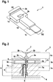
- FIG. 1 shows in a three-dimensional representation of a securing means 1.
- the securing means 1 is made of a particularly hard plastic.
- the securing means 1 has a securing portion 1a, a guiding portion 1b and a breaking portion 1c.
- the securing portion 1a has a first width B1 and the guide portion 1b and the interrupting portion 1c has a second width B2.
- the first width B1 is wider than the second width B2.
- the first width B1 is 10 mm and the second width B2 is 5 mm.
- the protrusion formed by the second width B2 forms, for example, a stop of the securing means 1.
- the fuse section 1a has e.g. a square base and the guide portion 1b and the interrupting portion 1c e.g. a rectangular elongated shape.
- the securing portion la has at least one nose 2a and a bridge 2b.
- the nose 2a forms with the projection of the second width B2 a stop for the securing means 1, wherein the stop will be described in more detail below.
- the web 2b extends over the entire second width B2 at an outer edge of the free end of the securing means 1 or securing portion 1a.
- the guide portion 1b immediately adjoins the securing portion 1a, and the interrupting portion 1c immediately adjoins the guide portion 1b.
- the sections 1a, b, c and the nose 2a and the web 2b are made in one piece from a plastic injection molding.
- the interrupting portion 1c forms an axial end of the securing means 1 and is offset to the guide portion 1b, so that the guide portion 1b and the interruption portion 1c have a different material thickness.
- FIG. 2 shows in a sectional view a detailed view of a fire alarm device 3, for example a battery-operated smoke detector and / or fire detector, with a housing 4.
- the housing 4 has a battery compartment 5, wherein the battery compartment 5 is closed by a battery cover 6.
- a battery 7a and a further battery 7c is arranged in the battery compartment 5.
- the batteries 7a, b are, for example, cylindrical and each have two poles.
- the battery compartment 5 has a battery contact 8 for the housing-side contacting of the batteries 7a, b.
- the battery contact 8 is formed as a sheet metal construction, wherein a sheet has been processed by forming.
- the battery 7a and the battery contact 8 define a contact region 9, wherein in the contact region 9, the battery 7a with the battery contact 9 is contacted.
- the battery cover 6 has at least a first and a second fixing web 6a, b.
- the fixing webs 6a, b are integrally connected to the battery cover 6 and extend from a battery compartment side of the battery cover 6 in the direction of the batteries 7a, b.
- the fixing webs 6a, b rest on a cylinder jacket surface of the batteries 7a, b in a form-fitting manner or are spaced apart from the cylinder jacket surface with a slight clearance, so that the batteries 7a, b are fixed in the battery compartment 5 in the direction of the battery cover 6.
- the battery cover 6 has further fixing webs, e.g. two fixing bars per battery, on.
- the battery cover 6 has a guide 11 for receiving the guide portion 1 b and for guiding the securing means 1 and an opening 10.
- the inner contour of the opening 10 and / or the guide 11 has a similar geometric shape as the outer contour of the guide portion 1b, so that the guide portion 1b is preferably guided with a small clearance in the opening 10 and / or the guide 11.
- the guide 11 is formed for example by two mutually parallel webs, ribs, etc., wherein these form an extension of the opening 10.
- the guide 11 is formed, for example, as a guide channel, which extends directly to the opening 10 in the direction of the battery 7a and / or the battery contact 8.
- the guide 11 extends to the contact region 9, so that the guide portion 1 b, in an assembled state of the securing means 1, is guided completely in the guide 11.
- the securing means 1 is shown in the assembled state.
- the interruption section 1c is arranged between the battery contact 8 and the battery 7a, so that contacting of the battery 7a with the battery contact 8 is prevented.
- the interruption portion 1c extends partially in the contact region 9, so that the battery contact 8 and the battery 7a are separated from each other.
- the interruption portion 1c extends, for example, completely over the entire contact area 9.
- the securing means 1 is fully inserted into the opening 10, so that the stop formed by the nose 2a and / or by the second width B2 rests on an outer side of the battery cover 6.
- the guide section 1 b is arranged in the guide 11, so that a mounting or dismounting direction of the securing means 1 is defined by the guide 11.
- the interruption portion 1c viewed in a cross section of the securing means 1, formed thinner than the guide portion 1b, so that insertion or withdrawal of the securing means 1 is facilitated.
- the thickness of the interruption portion 1c is less than 1 mm and the thickness of the guide portion 1b is more than 1.5 mm.
- the securing means 1 is sword-shaped, wherein the securing portion la forms a kind of handle.
- the handle has the function of forming a stop of the securing means 1 and a gripping aid, for example when pulling out the securing means 1.
- the nose 2a is located on the battery cover 6, so that further insertion of the securing means 1 is prevented.
- the web 2b forms in particular the gripping aid, so that, for example, a slipping of the fingers when pulling out of the securing means 1 is prevented.
- the securing means 1 is mirror-symmetrical, wherein the nose 2a and the bridge 2b are also arranged mirrored on the opposite side.
- FIG. 3 shows in a three-dimensional view of the housing 4 with the battery cover 6 and the securing means 1 from a mounting side.
- the housing 4 is formed for example as a square bowl.
- the battery cover 6 is formed, for example, as a flap, wherein the battery cover 6 is pivotally attached to the housing 4 via a first and a second hinge 12a, b.
- the housing 4 has a first and a second attachment receptacle 13a, b and a base receptacle 15, wherein the receptacles 15, 13a, b form the at least one receiving portion.
- the base receptacle 15 is arranged centrally on the mounting side and has a first and a second base stop 16a, b.
- the base receptacle 15 is formed as a cylindrical counterbore.
- the two base stops 16a, b are arranged inside the base receptacle 15 on the cylindrical surface of the cylinder, and e.g. designed as two opposing webs.
- the two fastening receivers 13a, b are arranged opposite one another on the mounting side concentrically with the base receptacle 15.
- the fastening receivers 13a, b are designed as flush countersunk segments.
- each circle segment is formed as an eighth segment.
- Each of the two fastening receptacles 13a, b has a fastening web 14.
- the attachment web 14 extends partially, e.g. in half, in the direction of rotation on an outer circular arc.
- the fastening web 14 forms a projection, so that, for example, a groove is formed between a base of the circle segment and the fastening web 14.
- the two fastening receptacles 13a, b are arranged point-mirrored to each other.
- FIG. 4 shows in a three-dimensional representation of the battery cover 6, from the FIG. 3 in a disassembled state with the securing means 1.
- the battery cover 6 has a bent shape.
- the securing means 1 is arranged centrally between the two hinges 12a, b.
- the nose 2a and the securing portion 1a are on the outside of the battery cover 6, so that the securing portion la can not be pushed further.
- the securing means 1 is perpendicular to the battery cover 6 from.
- FIG. 5 shows in a three-dimensional representation of a mounting plate 17 as a part of the fire detection device 1.
- the mounting plate 17 forms a mounting surface for mounting the housing 4 and has a base 18 and a first and a second fastening hooks 19a, b, as the fastening contour on.
- the base 18 is cylindrical, wherein the base 18 is receivable in the base receptacle 15. Furthermore, the base 18 has two opposite base circle segments 18a, b, for example, the base circle segments 18a, b are quarter segments, so that the base 18 has two different outer diameters.
- the first larger outer diameter, which is formed by the two base circle segments 18a, b at least approximately corresponds to the inner diameter of the base receptacle 15.
- the base 18 is insertable into the base receptacle 15, wherein a rotational movement of the housing 4 relative to the mounting plate 17 by the two base stops 16a, b is limited and the two Sockel Vietnamesesegmente 18a, b to the base stops 16a, b abut.
- the mounting plate 17 has a first and a second fastening hooks 19a, b.
- the two fastening hooks 19 a, b are arranged opposite one another concentrically with respect to the base 18.
- the two fastening hooks 19a, b are arranged facing away from each other towards the outside.
- the first attachment hook 19a can be received in the first attachment receptacle 13a and the second attachment hook 19b in the second attachment receptacle 13b.
- the two fastening receptacles 13a, b, the base receptacle 15, the two fastening hooks 19a, b and the base 18 together form a bayonet closure, wherein the housing 4 and the mounting plate 17 in particular by a plug-and-turn movement of the housing 4 relative to the mounting plate 17 are connectable.
- the housing 4 By plugging the housing 4 is placed on the mounting plate 17, so that the base 18 in the base receptacle 15 and the mounting hooks 19a, b are added to the mounting receptacles 13a, b.
- the housing 4 By the rotational movement, the housing 4 is rotated relative to the mounting plate 17, so that the two Sockel Vietnamesesegmente 18a, b bear against the base stops 16a, b and the two mounting hooks 19a, b in the groove between the base of the mounting receptacles 13a, b and the fastening webs 14 are guided, so that the housing 4 is connected to the mounting plate 17.
- the fastening hooks 19a, b form a positive connection and / or a frictional connection with the fastening web 14, so that the housing 4 is locked on the mounting plate 17.
- the mounting plate 17 is for attachment to a flat surface, e.g. Wall, ceiling, beams, etc. trained and / or suitable.
- a flat surface e.g. Wall, ceiling, beams, etc. trained and / or suitable.
- the mounting plate on a first and a second fastener receiving 20a, b.
- the two fastener receptacles 20a, b are formed as elongated holes and serve to receive a screw, wherein the screw is guided by the fastener receiving means 20a, b and the mounting plate 17 attached to the flat surface.
- FIG. 6 The fuse portion la is for example perpendicular to the battery cover 6, wherein the securing portion la prevents plugging movement of the housing 4 in the direction of the mounting plate 17.
- the fuse portion la for example, longer than the socket 18.
- the housing 4 can not be brought close enough to the mounting plate 17, so that the mounting hooks 19a, b not in the corresponding mounting receptacles 13a, b and / or the base 18 not can be accommodated in the base receptacle 15.
- the securing means 1 For mounting of the housing 4 on the mounting plate 17, the securing means 1 must be removed, whereby the assembly is made possible and at the same time the battery 7a contacted with the battery contact 8, so that the fire alarm device 3 is supplied with power.
Landscapes
- Chemical & Material Sciences (AREA)
- Analytical Chemistry (AREA)
- Business, Economics & Management (AREA)
- Emergency Management (AREA)
- Physics & Mathematics (AREA)
- General Physics & Mathematics (AREA)
- Fire Alarms (AREA)
- Fire-Detection Mechanisms (AREA)
- Battery Mounting, Suspending (AREA)
Description
- Brandmeldevorrichtung für ein Gebäude, mit mindestens einer Batterie zur Stromversorgung der Brandmeldevorrichtung, mit einem Gehäuse, wobei das Gehäuse ein Batteriefach zur Aufnahme der Batterie aufweist, wobei das Batteriefach mindestens einen Batteriekontakt zur Kontaktierung der Batterie aufweist, wobei das Gehäuse eine Montageseite aufweist, wobei das Gehäuse mit der Montageseite an einer Montagefläche befestigbar ist. Ferner betrifft die Erfindung ein Verfahren zur Montage der Brandmeldevorrichtung mit den Merkmalen des Anspruchs 9 sowie ein Gebäude mit der Brandmeldevorrichtung mit den Merkmalen des Anspruchs 10.
- Zur Früherkennung von Bränden in öffentlichen oder privaten Räumlichkeiten werden üblicherweise automatische Brandmeldeeinrichtungen eingesetzt. Derartige Brandmeldeeinrichtungen umfassen typischerweise mindestens einen Brandmelder, welcher auf Basis von brandspezifischen Größen, wie zum Beispiel Rauch, Rußpartikeln, Temperatur oder Gaskonzentrationen einen Brand in seiner Umgebung frühzeitig detektiert und Alarm auslösen kann. Insbesondere für den Heimbereich werden Brandmeldeeinrichtungen eingesetzt, welche batteriebetrieben sind. Meist sind die Batterien dem Melder in der Verpackung beigelegt, so dass diese vor dem erstmaligen Betrieb zunächst in den Melder eingelegt werden müssen. Um eine Stromversorgung vor der Befestigung des Rauchmelders z.B. an einer Zimmerdecke zu gewährleisten, existieren Rauchmelder, welche eine Befestigung bei Fehlen der Batterie verhindern.
- Die Druckschrift
DE 10 2010 027 944 A1 offenbart ein Gehäuse für einen Brandmelder, insbesondere für einen Rauchmelder, mit einem Batterieaufnahmeabschnitt für mindestens eine Batterie, wobei der Batterieaufnahmeabschnitt mindestens einen Batteriekontakt für die mindestens eine Batterie aufweist, mit einem Abdeckungsabschnitt, welcher zumindest einen Teil einer Sicherungseinrichtung bildet, die zur Sicherung der mindestens einen Batterie in einem in den Batterieaufnahmeabschnitt eingelegten Zustand ausgebildet ist, und welcher mit dem Batterieaufnahmeabschnitt verbindbar ist, mit einem ersten Sperrmittel, das mit dem Batterieaufnahmeabschnitt gekoppelt ist, und mit einem zweiten Sperrmittel, das mit dem Abdeckungsabschnitt gekoppelt ist, wobei erstes und zweites Sperrmittel so ausgebildet und/oder angeordnet sind, dass diese eine Verbindung des Batterieaufnahmeabschnitts mit dem Abdeckungsabschnitt sperren, wenn mindestens eine Batterie in dem Batterieaufnahmeabschnitt fehlt, wobei das erste Sperrmittel durch den Batteriekontakt als Betätigungsabschnitt von einer Sperrstellung in eine Freigabestellung überführbar ist. Der nächstliegende Stand der Technik wird in derJP-A-2011222041 - Im Rahmen der Erfindung wird eine Brandmeldevorrichtung mit den Merkmalen des Anspruchs 1, ein Verfahren mit den Merkmalen des Anspruchs 9 sowie ein Gebäude mit den Merkmalen des Anspruchs 10 offenbart. Bevorzugte oder vorteilhafte Ausführungsformen der Erfindung ergeben sich aus den Unteransprüchen, der nachfolgenden Beschreibung sowie den beigefügten Figuren.
- Gegenstand der Erfindung ist eine Brandmeldevorrichtung für ein Gebäude. Insbesondere ist die Brandmeldevorrichtung an einer Wand und/oder an einer Decke eines Raums des Gebäudes befestigt und/oder befestigbar. Vorzugsweise weist die Brandmeldevorrichtung eine Sensorik auf, die dazu ausgebildet ist, Brandemissionen, wie z.B. Brandgas- und/oder Brandpartikelkonzentrationen zu detektieren. Vorzugsweise ist die Sensorik als eine chemische, optische, fotoelektrische Sensorik oder als eine lonisationssensorik ausgebildet. Besonders bevorzugt ist die Brandmeldevorrichtung ausgebildet einen Brandalarm auf Basis der Detektion auszugeben.
- Die Brandmeldevorrichtung weist mindestens eine Batterie zur Stromversorgung der Brandmeldevorrichtung auf. Insbesondere ist unter Batterie ein Energiespeicher im weiten Sinne, z.B. auch ein aufladbarer Akkumulator o.ä., zu verstehen. Die Brandmeldevorrichtung weist insbesondere mehr als eine, vorzugsweise mehr als drei Batterien auf, im Speziellen mehr als fünf Batterien.
- Die Brandmeldevorrichtung weist ein Gehäuse auf. Insbesondere ist das Gehäuse einteilig oder mehrteilig ausgebildet. Beispielsweise weist das Gehäuse mindestens zwei Gehäuseteile auf, welche beispielsweise über eine Klips- und/oder Schraubverbindung miteinander verbunden und/oder verbindbar sind. Besonders bevorzugt ist das Gehäuse aus Kunststoff gefertigt.
- Das Gehäuse weist ein Batteriefach zur Aufnahme der Batterie auf. Insbesondere ist das Batteriefach ausgebildet eine oder mehrere Batterien aufzunehmen. Optional ergänzend weist das Gehäuse mindestens ein weiteres Batteriefach zur Aufnahme mindestens einer weiteren Batterie auf.
- Das Batteriefach weist mindestens einen Batteriekontakt zur Kontaktierung der Batterie auf. Insbesondere hat der Batteriekontakt die Funktion einen elektrischen Kontakt zwischen der Batterie und z.B. der Sensorik, einer LED etc. herzustellen, so dass ein Batteriestrom übertragen wird. Vorzugsweise ist der Batteriekontakt als eine Feder und/oder als ein einfach oder mehrfach gebogenes und/oder umgeformtes Blech ausgebildet. Besonders bevorzugt bilden die Batterie und der Batteriekontakt einen Kontaktbereich, in welchem die Batterie mit dem Batteriekontakt in Verbindung steht.
- Das Gehäuse weist eine Montageseite auf, wobei das Gehäuse mit der Montageseite an einer Montagefläche befestigbar ist. Insbesondere ist die Montageseite eine ebene Unterseite des Gehäuses, so dass das Gehäuse planparallel zu der Montagefläche anordbar ist. Vorzugsweise ist die Montagefläche durch die Wand und/oder die Decke des Raumes gebildet. Besonders bevorzugt jedoch ist die Montagefläche durch eine Befestigungsstruktur gebildet. Insbesondere ist das Batteriefach montageseitig angeordnet.
- Im Rahmen der Erfindung wird vorgeschlagen, dass die Brandmeldevorrichtung ein Sicherungsmittel aufweist, wobei das Sicherungsmittel an der Montageseite anordbar ist. Insbesondere wird das Sicherungsmittel vor der Auslieferung bzw. bei der Fertigung der Brandmeldevorrichtung an der Montageseite in das Gehäuse eingebracht. Vorzugsweise wird das Sicherungsmittel vor einer Montage der Brandmeldevorrichtung von der Montageseite entfernt. Im Speziellen ist das Sicherungsmittel stiftförmig und/oder plattenförmig und/oder schwertförmig und/oder rechteckförmig und/oder länglich. Insbesondere ist das Sicherungsmittel im Bereich des Batteriefaches angeordnet und/oder anordbar.
- Das Sicherungsmittel unterbricht die Kontaktierung zwischen der Batterie und dem Batteriekontakt und verhindert zugleich eine Montage des Gehäuses mit der Montageseite an der Montagefläche. Insbesondere trennt das Sicherungsmittel die Batterie von dem Batteriekontakt. Vorzugsweise ist das Sicherungsmittel zwischen dem Batteriekontakt und der Batterie eingeschoben. Besonders bevorzugt ist das Sicherungsmittel als ein Isolator ausgebildet. Insbesondere ragt das Sicherungsmittel aus dem Batteriefach heraus und/oder steht von dem Gehäuse ab, so dass eine Montage des Gehäuses an der Montagefläche verhindert wird.
- Optional ergänzend ist jeder Batterie ein Sicherungsmittel zugeordnet, so dass eine Stromversorgung nur dann erfolgt, wenn alle Sicherungsmittel entfernt wurden.
- Der Vorteil der Erfindung besteht darin, dass durch die bereits eingelegten Batterien eine Erleichterung der Montage für den Kunden realisiert wird. Insbesondere wird durch das Sicherungsmittel sichergestellt, dass die Brandmeldevorrichtung nur dann montiert werden kann, wenn diese ordnungsgemäß mit Strom versorgt wird. Durch die einfache Anordnung des Sicherungsmittels ist eine besonders kostengünstige Fertigung des Sicherungsmittels möglich. Ein weiterer Vorteil besteht darin, dass eine schnelle und einfache Montage und Demontage des Sicherungsmittels gewährleistet ist, so dass kein erheblicher Zeitaufwand bei der Fertigung sowie bei der Montage der Brandmeldevorrichtung entsteht.
- In einer bevorzugten Weiterbildung weist das Sicherungsmittel einen Unterbrechungsabschnitt zur Unterbrechung der Kontaktierung auf. Insbesondere ist der Unterbrechungsabschnitt im Bereich des Batteriekontaktes und/oder im Bereich der Batterie angeordnet. Insbesondere erstreckt sich der Unterbrechungsabschnitt zumindest teilweise oder vollständig über den gesamten Kontaktbereich. Vorzugsweise beaufschlagt der Batteriekontakt die Batterie mit einer Federkraft, wobei besonders bevorzugt der Unterbrechungsabschnitt durch den Batteriekontakt formschlüssig und/oder kraftschlüssig und/oder reibschlüssig zwischen dem Batteriekontakt und der Batterie gehalten ist. Somit wird insbesondere ein Herausfallen des Sicherungsmittels verhindert.
- Das Sicherungsmittel weist einen Führungsabschnitt zur Führung des Sicherungsmittels auf, wobei der Unterbrechungsabschnitt einen dünneren Querschnitt als der Führungsabschnitt aufweist. Insbesondere schließt sich der Führungsabschnitt unmittelbar an den Unterbrechungsabschnitt an. Vorzugsweise sind der Unterbrechungsabschnitt und der Führungsabschnitt durch ein Umformverfahren und/oder ein Urformverfahren und/oder ein Trennverfahren gebildet. Besonders bevorzugt jedoch ist das Sicherungsmittel aus einem einmaterialigen Guss, insbesondere Kunststoffspritzguss, gefertigt.
- Insbesondere ist das Sicherungsmittel von dem Führungsabschnitt zu dem Unterbrechungsabschnitt hin dünner werdend ausgeformt, so dass das Einstecken und Trennen des Sicherungsmittels zwischen der Batterie und dem Batteriekontakt leichtgängig ist. Vorzugsweise weisen der Unterbrechungsabschnitt und der Führungsabschnitt in einer Vorderansicht die gleiche Breite und in einer Seitenansicht unterschiedliche Dicken auf. Insbesondere weist der Unterbrechungsabschnitt eine geringere Dicke als der Führungsabschnitt auf. Insbesondere beträgt die Dicke des Unterbrechungsabschnitts weniger als 80%, vorzugsweise weniger als 50%, im Speziellen weniger als 10% der Dicke des Führungsabschnitts.
- In einer bevorzugten Ausgestaltung weist das Gehäuse eine Batterieabdeckung zur Abdeckung des Batteriefachs auf. Insbesondere ist die Abdeckung als ein Deckel oder als ein Boden ausgebildet. Vorzugsweise ist der Deckel klappbar und/oder abnehmbar und/oder schwenkbar an dem Gehäuse und/oder in dem Batteriefach befestigt. Beispielsweise ist die Batterieabdeckung über ein Scharnier und/oder über eine Steckverbindung und/oder über eine Rastverbindung und/oder eine Klipsverbindung mit dem Gehäuse verbunden. Besonders bevorzugt verschließt die Batterieabdeckung das Batteriefach, so dass ein Herausfallen der Batterien verhindert ist.
- Das Batteriefach und/oder die Batterieabdeckung weisen eine Führung zur Aufnahme des Führungsabschnitts auf, wobei das Sicherungsmittel in der Führung geführt ist. Insbesondere ist die Führung als ein Kanal oder eine Schiene oder mindestens ein, vorzugsweise mehrere, Stege ausgebildet. Vorzugsweise wird das Sicherungsmittel entlang der Führung in Richtung des Batteriekontaktes geführt. Insbesondere weist die Batterieabdeckung im Bereich des Batteriekontaktes eine Öffnung auf, so dass das Sicherungsmittel vorzugsweise durch die Öffnung geführt ist. Besonders bevorzugt schließt sich die Führung mittelbar oder unmittelbar an die Öffnung an. Insbesondere weist die Öffnung und/oder die Führung eine ähnliche Form wie der Führungsabschnitt auf. Vorzugsweise erstreckt sich die Führung von der Öffnung in Richtung des Batteriekontaktes. Alternativ ist die Führung nur durch die Öffnung gebildet. Im Speziellen erstreckt sich die Führung bis zu dem Batteriekontakt, so dass der Führungsabschnitt vollständig in der Führung aufgenommen und/oder aufnehmbar ist.
- Alternativ erstreckt sich die Führung nur teilweise in Richtung des Batteriekontakts, so dass der Führungsabschnitt nur teilweise in der Führung aufgenommen ist. Insbesondere beträgt die Erstreckung der Führung in Richtung des Batteriekontaktes mehr als 10%, vorzugsweise mehr als 50%, im Speziellen mehr als 80% der Länge des Führungsabschnitts. Alternativ oder optional ergänzend beträgt die Erstreckung der Führung in Richtung des Batteriekontaktes weniger als 90%, vorzugsweise weniger als 60%, im Speziellen weniger als 30% der Länge des Führungsabschnitts.
- In einer bevorzugten Umsetzung weist das Sicherungsmittel einen Sicherungsabschnitt auf. Insbesondere schließt sich der Sicherungsabschnitt unmittelbar an den Führungsabschnitt an. Vorzugsweise bildet der Sicherungsabschnitt einen Anschlag, wobei der Sicherungsabschnitt auf der Batterieabdeckung und/oder der Montageseite aufliegt, so dass das Sicherungsmittel nur bis zu dem Anschlag in die Öffnung einschiebbar ist. Insbesondere sind der Sicherungsabschnitt und der Führungsabschnitt durch ein Umformverfahren und/oder ein Urformverfahren und/oder ein Trennverfahren gebildet. Besonders bevorzugt jedoch sind der Führungsabschnitt und/oder der Sicherungsabschnitt und/oder der Unterbrechungsabschnitt aus einem einmaterialigen Guss, insbesondere Kunststoffspritzguss gefertigt.
- Der Sicherungsabschnitt steht an der Montageseite ab, so dass der Sicherungsabschnitt eine Störkontur bildet und somit eine Montage des Gehäuses an der Montagefläche verhindert wird. Insbesondere definiert die Montageseite der Brandmeldevorrichtung eine Montageebene, wobei der Sicherungsabschnitt senkrecht oder zumindest annähernd senkrecht zu der Montageebne angeordnet ist. Vorzugsweise steht der Sicherungsabschnitt so weit ab, dass eine horizontale und/oder eine vertikale ebene Montage an der Montagefläche verhindert wird. Insbesondere steht der Sicherungsabschnitt mehr als 5 mm, vorzugsweise mehr 10 mm, im Speziellen mehr als 20 mm von der Montageseite ab. Alternativ oder optional ergänzend steht der Sicherungsabschnitt weniger als 30 mm, vorzugsweise weniger als 15 mm, im Speziellen weniger als 8 mm von der Montageseite ab.
- In einer bevorzugten Ausgestaltung weist die Brandmeldevorrichtung eine Montageplatte auf, wobei die Montageplatte die Montagefläche bildet. Insbesondere wird die Montageplatte an einer ebenen Fläche, vorzugsweise der Wand und/oder der Decke, befestigt. Besonders bevorzugt wird die Montageplatte an die ebene Fläche geschraubt und/oder geklebt. Insbesondere wird anschließend das Gehäuse mit der Montageplatte verbunden. Besonders bevorzugt bildet die Montageplatte die Befestigungsstruktur.
- Insbesondere weist die Montageplatte mindestens eine Befestigungsmittelaufnahme zur Aufnahme mindestens eines Befestigungsmittels auf. Beispielsweise ist die Befestigungsmittelaufnahme ein Langloch und/oder eine schlüsselochförmige Bohrung und das Befestigungsmittel eine Schraube. Vorzugsweise ist das Befestigungsmittel durch die Befestigungsmittelaufnahme geführt, so dass die Montageplatte an der ebenen Fläche befestigt ist.
- Die Montageplatte und das Gehäuse bilden eine Steck-Dreh-Verbindung, wobei der Sicherungsabschnitt eine Steckbewegung und/oder eine Drehbewegung des Gehäuses relativ zu der Montageplatte verhindert. Insbesondere ist die Steck-Dreh-Verdingung als ein Bajonettverschluss ausgebildet. Vorzugsweise weist das Gehäuse auf der Montageseite mindestens einen Aufnahmeabschnitt zur Aufnahme einer Befestigungskontur der Montageplatte auf. Beispielsweise ist die Befestigungskontur als ein Sockel und/oder mindestens ein Befestigungshaken ausgebildet. Besonders bevorzugt wird durch die Steck-Dreh-Bewegung ein Formschluss und/oder ein Kraftschluss und/oder ein Reibschluss der Befestigungskontur mit dem Aufnahmeabschnitt gebildet.
- Insbesondere verhindert der Sicherungsabschnitt durch seine Störkontur die Steckbewegung und/oder eine Aufnahme der Befestigungskontur in dem Aufnahmeabschnitt, so dass eine Befestigung des Gehäuses an der Montageplatte verhindert wird. Alternativ oder optional ergänzend verhindert der Sicherungsabschnitt durch seine Störkontur die Drehbewegung und/oder eine Drehung der Befestigungskontur in dem Aufnahmeabschnitt, so dass eine Befestigung des Gehäuses an der Montageplatte verhindert wird.
- In einer bevorzugten Realisierung ist das Sicherungsmittel oder zumindest der Unterbrechungsabschnitt aus einem elektrisch isolierenden Material gebildet. Insbesondere ist das elektrisch isolierende Material ein Kunststoff und/oder eine Keramik. Vorzugsweise besteht das Sicherungsmittel vollständig aus dem elektrisch isolierenden Material. Alternativ besteht der Unterbrechungsabschnitt aus dem elektrisch isolierenden Material oder weist eine Beschichtung aus dem elektrisch isolierenden Material, z.B. eine Gummibeschichtung, auf.
- In einer weiteren Umsetzung ist das elektrisch isolierende Material als ein hochfester Kunststoff ausgebildet. Insbesondere wird durch den hochfesten Kunststoff eine möglichst dünne Ausgestaltung des Unterbrechungsabschnitts ermöglicht, so dass das Sicherungsmittel leicht zwischen der Batterie und dem Batteriekontakt einsetzbar ist. Beispielsweise ist der Kunststoff ein Copolymerisat, z.B. Cyclo-Olefin-Copolymere oder ein Polyaddukt, z.B. Epoxidharz oder der Kunststoff Polypropylen. Optional ergänzend ist der Kunststoff mit Glasfasern verstärkt.
- In einer weiteren Ausgestaltung weist das Sicherungsmittel eine andere Farbe als das Gehäuse auf. Insbesondere weist das Sicherungsmittel, besonders bevorzugt der Sicherungsabschnitt, eine Signalfarbe auf. Vorzugsweise ist die Signalfarbe eine Neonfarbe und/oder eine Leuchtfarbe. Beispielsweise ist die Farbe des Sicherungsmittels rot und/oder gelb und/oder orange und/oder die Farbe des Gehäuses weiß und/oder grau.
- Ein weiterer Gegenstand der Erfindung bildet ein Verfahren zur Montage der Brandmeldevorrichtung wie diese zuvor beschrieben wurde beziehungsweise nach einem der vorhergehenden Ansprüche mit den Schritten, Sicherungsmittel entfernen, kontaktieren der Batterie mit dem Batteriekontakt, so dass die Brandmeldevorrichtung mit Strom versorgt wird, Gehäuse an der Montagefläche oder der Montageplatte montieren.
- Ein weiterer Gegenstand der Erfindung bildet ein Gebäude mit der Brandmeldevorrichtung wie diese zuvor beschrieben wurde beziehungsweise nach einem der vorhergehenden Ansprüche.
- Weitere Merkmale, Vorteile und Wirkungen der Erfindung ergeben sich aus der nachfolgenden Beschreibung bevorzugter Ausführungsbeispiele der Erfindung. Dabei zeigen:
- Figur 1
- zeigt in einer dreidimensionalen Darstellung ein Sicherungsmittel für eine Brandmeldevorrichtung;
- Figur 2
- zeigt in einer Schnittdarstellung eine Detailansicht eines Batteriefachs der Brandmeldevorrichtung;
- Figur 3
- zeigt in einer dreidimensionalen Darstellung ein Gehäuse der Brandmeldevorrichtung;
- Figur 4
- zeigt in einer dreidimensionalen Darstellung eine Batterieabdeckung für die Brandmeldevorrichtung mit dem Sicherungsmittel;
- Figur 5
- zeigt in einer dreidimensionalen Darstellung eine Montageplatte der Brandmeldevorrichtung;
- Figur 6
- zeigt in einer Seitenansicht die Brandmeldevorrichtung mit der Montageplatte, dem Gehäuse, der Batterieabdeckung und dem Sicherungsmittel.
- Einander entsprechende oder gleiche Teile sind in den Figuren jeweils mit den gleichen Bezugszeichen versehen.
-
Figur 1 zeigt in einer dreidimensionalen Darstellung ein Sicherungsmittel 1. Beispielsweise ist das Sicherungsmittel 1 aus einem besonders harten Kunststoff gefertigt. Das Sicherungsmittel 1 weist einen Sicherungsabschnitt 1a, einen Führungsabschnitt 1b und einen Unterbrechungsabschnitt 1c auf. Der Sicherungsabschnitt la weist eine erste Breite B1 und der Führungsabschnitt 1b und der Unterbrechungsabschnitt 1c eine zweite Breite B2 auf. Die erste Breite B1 ist dabei breiter als die zweite Breite B2. Beispielsweise beträgt die erste Breite B1 10 mm und die zweite Breite B2 5 mm. Der durch die zweite Breite B2 gebildete Überstand bildet beispielsweise einen Anschlag des Sicherungsmittels 1. - Der Sicherungsabschnitt la weist z.B. eine quadratische Grundfläche und der Führungsabschnitt 1b und der Unterbrechungsabschnitt 1c z.B. eine rechteckige längliche Form auf. Der Sicherungsabschnitt la weist mindestens eine Nase 2a und einen Steg 2b auf. Die Nase 2a bildet mit dem Überstand der zweiten Breite B2 einen Anschlag für das Sicherungsmittel 1, wobei der Anschlag nachfolgend noch genauer beschrieben wird. Der Steg 2b erstreckt sich über die gesamte zweite Breite B2 an einer Außenkante des freien Endes des Sicherungsmittels 1 bzw. Sicherungsabschnitts la.
- Der Führungsabschnitt 1b schließt sich unmittelbar an den Sicherungsabschnitt la und der Unterbrechungsabschnitt 1c schließt sich unmittelbar an den Führungsabschnitt 1b an. Beispielsweise sind die Abschnitte 1a, b, c sowie die Nase 2a und der Steg 2b einteilig aus einem Kunststoffspritzguss gefertigt. Der Unterbrechungsabschnitt 1c bildet ein axiales Ende des Sicherungsmittels 1 und ist zu dem Führungsabschnitt 1b abgesetzt, so dass der Führungsabschnitt 1b und der Unterbrechungsabschnitt 1c eine unterschiedliche Materialstärke aufweisen.
-
Figur 2 zeigt in einer Schnittdarstellung eine Detailansicht einer Brandmeldevorrichtung 3, z.B. ein batteriebetriebener Rauchmelder und/oder Feuermelder, mit einem Gehäuse 4. Das Gehäuse 4 weist ein Batteriefach 5 auf, wobei das Batteriefach 5 durch eine Batterieabdeckung 6 abgeschlossen ist. In dem Batteriefach 5 ist eine Batterie 7a und eine weitere Batterie 7c angeordnet. Die Batterien 7a, b sind z.B. zylinderförmig ausgebildet und weisen jeweils zwei Pole auf. Das Batteriefach 5 weist einen Batteriekontakt 8 zur gehäuseseitigen Kontaktierung der Batterien 7a, b auf. Der Batteriekontakt 8 ist als eine Blechkonstruktion ausgebildet, wobei ein Blech mittels Umformen bearbeitet wurde. Die Batterie 7a und der Batteriekontakt 8 definieren einen Kontaktbereich 9, wobei in dem Kontaktbereich 9 die Batterie 7a mit dem Batteriekontakt 9 kontaktierbar ist. - Die Batterieabdeckung 6 weist mindestens einen ersten und einen zweiten Fixierungssteg 6a, b auf. Die Fixierungsstege 6a, b sind einteilig mit der Batterieabdeckung 6 verbunden und erstrecken sich von einer batteriefachseitigen Seite der Batterieabdeckung 6 in Richtung der Batterien 7a, b. Beispielsweise liegen die Fixierungsstege 6a, b an einer Zylindermantelfläche der Batterien 7a, b formschlüssig an oder sind mit einem geringen Spiel zu der Zylindermantelfläche beabstandet, so dass die Batterien 7a, b in dem Batteriefach 5 in Richtung der Batterieabdeckung 6 fixiert werden. Beispielsweise weist die Batterieabdeckung 6 weitere Fixierungsstege, z.B. zwei Fixierungsstege pro Batterie, auf.
- Die Batterieabdeckung 6 weist eine Führung 11 zur Aufnahme des Führungsabschnitts 1b und zur Führung des Sicherungsmittels 1 sowie eine Öffnung 10 auf. Beispielsweise weist die Innenkontur der Öffnung 10 und/oder der Führung 11 eine ähnliche geometrische Form auf wie die Außenkontur des Führungsabschnitts 1b, so dass der Führungsabschnitt 1b vorzugsweise mit einem geringen Spiel in der Öffnung 10 und/oder der Führung 11 geführt ist.
- Die Führung 11 ist beispielsweise durch zwei parallel zueinander verlaufende Stege, Rippen etc. gebildet, wobei diese eine Verlängerung der Öffnung 10 bilden. Alternativ ist die Führung 11 z.B. als ein Führungskanal ausgebildet, welcher sich unmittelbar an die Öffnung 10 in Richtung der Batterie 7a und/oder des Batteriekontaktes 8 erstreckt. Alternativ erstreckt sich die Führung 11 bis zu dem Kontaktbereich 9, so dass der Führungsabschnitt 1b, in einem Montagezustand des Sicherungsmittels 1, vollständig in der Führung 11 geführt ist.
- In dem gezeigten Ausführungsbeispiel ist das Sicherungsmittel 1 in dem Montagezustand dargestellt. Dabei ist der Unterbrechungsabschnitt 1c zwischen dem Batteriekontakt 8 und der Batterie 7a angeordnet, so dass eine Kontaktierung der Batterie 7a mit dem Batteriekontakt 8 verhindert wird. Dadurch ist die Stromversorgung der Brandmeldevorrichtung 3 unterbrochen und die Brandmeldevorrichtung 3 somit außer Betrieb. Der Unterbrechungsabschnitt 1c erstreckt sich dabei teilweise in dem Kontaktbereich 9, so dass der Batteriekontakt 8 und die Batterie 7a voneinander getrennt sind. Alternativ erstreckt sich der Unterbrechungsabschnitt 1c beispielsweise vollständig über den gesamten Kontaktbereich 9.
- Das Sicherungsmittel 1 ist vollständig in die Öffnung 10 eingeschoben, so dass der durch die Nase 2a und/oder durch die zweite Breite B2 gebildete Anschlag auf einer Außenseite der Batterieabdeckung 6 anliegt. Der Führungsabschnitt 1b ist in der Führung 11 angeordnet, so dass durch die Führung 11 eine Montage- bzw. Demontagerichtung des Sicherungsmittels 1 definiert wird. Der Unterbrechungsabschnitt 1c ist, in einem Querschnitt des Sicherungsmittels 1 betrachtet, dünner ausgeformt als der Führungsabschnitt 1b, so dass ein Einschieben bzw. ein Herausziehen des Sicherungsmittels 1 erleichtert wird. Beispielsweise beträgt die Dicke des Unterbrechungsabschnittes 1c weniger als 1 mm und die Dicke des Führungsabschnitts 1b mehr als 1,5 mm.
- In der gezeigten Schnittdarstellung ist das Sicherungsmittel 1 schwertförmig, wobei der Sicherungsabschnitt la eine Art Griffstück bildet. Beispielsweise hat das Griffstück die Funktion einen Anschlag des Sicherungsmittels 1 sowie eine Greifhilfe z.B. beim Herausziehen des Sicherungsmittels 1 zu bilden. Die Nase 2a liegt an der Batterieabdeckung 6, so dass ein weiteres Einschieben des Sicherungsmittels 1 verhindert wird. Der Steg 2b bildet insbesondere die Greifhilfe, so dass z.B. ein Abrutschen der Finger beim Herausziehen des Sicherungsmittels 1 verhindert wird. Das Sicherungsmittel 1 ist spiegelsymmetrisch ausgebildet, wobei die Nase 2a und der Steg 2b gespiegelt ebenfalls auf der gegenüberliegenden Seite angeordnet sind.
- Die
Figur 3 zeigt in einer dreidimensionalen Darstellung das Gehäuse 4 mit der Batterieabdeckung 6 und dem Sicherungsmittel 1 von einer Montageseite. Das Gehäuse 4 ist beispielsweise als eine quadratische Schüssel ausgebildet. Die Batterieabdeckung 6 ist beispielsweise als eine Klappe ausgebildet, wobei die Batterieabdeckung 6 über ein erstes und ein zweites Scharnier 12a, b schwenkbar an dem Gehäuse 4 befestigt ist. - Das Gehäuse 4 weist eine erste und eine zweite Befestigungsaufnahme 13a, b sowie eine Sockelaufnahme 15 auf, wobei die Aufnahmen 15, 13a, b den mindestens einen Aufnahmeabschnitt bilden. Die Sockelaufnahme 15 ist mittig auf der Montageseite angeordnet und weist einen ersten und einen zweiten Sockelanschlag 16a, b auf. Die Sockelaufnahme 15 ist als eine zylinderförmige Plansenkung ausgebildet. Die beiden Sockelanschläge 16a, b sind innerhalb der Sockelaufnahme 15 an der Zylindermantelfläche angeordnet und z.B. als zwei gegenüberliegende Stege ausgebildet.
- Die beiden Befestigungsaufnahmen 13a, b sind gegenüberliegend voneinander auf der Montageseite konzentrisch zu der Sockelaufnahme 15 angeordnet. Die Befestigungsaufnahmen 13a, b sind als plangesenkte Kreissegmente ausgebildet. Beispielsweise ist jedes Kreissegment als ein Achtelsegment ausgebildet. Jede der beiden Befestigungsaufnahmen 13a, b weist einen Befestigungssteg 14 auf. Der Befestigungssteg 14 erstreckt sich dabei teilweise, z.B. zur Hälfte, in Umlaufrichtung an einem äußeren Kreisbogen. Der Befestigungssteg 14 bildet einen Überstand, so dass beispielsweise ein Nut zwischen einer Grundfläche des Kreissegments und dem Befestigungssteg 14 gebildet ist. Die beiden Befestigungsaufnahmen 13a, b sind punktgespiegelt zueinander angeordnet.
-
Figur 4 zeigt in einer dreidimensionalen Darstellung die Batterieabdeckung 6, aus derFigur 3 , in einem demontierten Zustand mit dem Sicherungsmittel 1. Die Batterieabdeckung 6 weist eine gebogene Form auf. Beispielsweise wird die Batterieabdeckung 6 bei der Fertigung durch ein Trennverfahren aus dem Gehäuse 4 getrennt, so dass die Batterieabdeckung 6 in einem montierten Zustand mit dem Gehäuse 4 wieder die Gehäuseform vervollständigt. Das Sicherungsmittel 1 ist mittig zwischen den beiden Scharnieren 12a, b angeordnet. Die Nase 2a und der Sicherungsabschnitt la liegen auf der Außenseite der Batterieabdeckung 6 auf, so dass der Sicherungsabschnitt la nicht weiter eingeschoben werden kann. Zum Beispiel steht das Sicherungsmittel 1 senkrecht zu der Batterieabdeckung 6 ab. -
Figur 5 zeigt in einer dreidimensionalen Darstellung eine Montageplatte 17 als ein Bestandteil der Brandmeldevorrichtung 1. Die Montageplatte 17 bildet eine Montagefläche zur Montage des Gehäuses 4 und weist einen Sockel 18 und einen ersten und einen zweiten Befestigungshaken 19a, b, als die Befestigungskontur, auf. Der Sockel 18 ist zylinderförmig ausgebildet, wobei der Sockel 18 in der Sockelaufnahme 15 aufnehmbar ist. Ferner weist der Sockel 18 zwei gegenüberliegende Sockelkreissegmente 18a, b auf, beispielsweise sind die Sockelkreissegmente 18a, b Viertelsegmente, so dass der Sockel 18 zwei unterschiedliche Außendurchmesser aufweist. Der erste größere Außendurchmesser, welcher durch die beiden Sockelkreissegmente 18a, b gebildet ist, entspricht zumindest annähernd dem Innendurchmesser der Sockelaufnahme 15. Der zweite kleinere Außendurchmesser, welcher durch die Zylindermantelfläche des Sockels 18 gebildet ist, entspricht zumindest annähernd dem Abstand zwischen den beiden Sockelanschlägen 16a, b. Der Sockel 18 ist in die Sockelaufnahme 15 einsetzbar, wobei eine Drehbewegung des Gehäuses 4 relativ zu der Montageplatte 17 durch die beiden Sockelanschläge 16a, b begrenzt wird und die beiden Sockelkreissegmente 18a, b an den Sockelanschlägen 16a, b anstoßen. - Die Montageplatte 17 weist einen ersten und einen zweiten Befestigungshaken 19a, b auf. Die beiden Befestigungshaken 19a, b sind gegenüberliegend voneinander konzentrisch zu dem Sockel 18 angeordnet. Die beiden Befestigungshaken 19a, b sind voneinander abgewandt nach außen hin angeordnet. Der erste Befestigungshaken 19a ist in der ersten Befestigungsaufnahme 13a und der zweite Befestigungshaken 19b in der zweiten Befestigungsaufnahme 13b aufnehmbar. Die beiden Befestigungsaufnahmen 13a, b, die Sockelaufnahme 15, die beiden Befestigungshaken 19a, b und der Sockel 18 bilden zusammen einen Bajonett-Verschluss, wobei das Gehäuse 4 und die Montageplatte 17 insbesondere durch eine Steck-Dreh-Bewegung des Gehäuses 4 relativ zu der Montageplatte 17 verbindbar sind.
- Durch die Steckbewegung wird das Gehäuse 4 auf die Montageplatte 17 aufgesetzt, so dass der Sockel 18 in der Sockelaufnahme 15 und die Befestigungshaken 19a, b in den Befestigungsaufnahmen 13a, b aufgenommen sind. Durch die Drehbewegung wird das Gehäuse 4 relativ zu der Montageplatte 17 gedreht, so dass die beiden Sockelkreissegmente 18a, b an den Sockelanschlägen 16a, b anliegen und die beiden Befestigungshaken 19a, b in der Nut zwischen der Grundfläche der Befestigungsaufnahmen 13a, b und der Befestigungsstege 14 geführt sind, so dass das Gehäuse 4 mit der Montageplatte 17 verbunden ist. Insbesondere bilden die Befestigungshaken 19a, b mit dem Befestigungssteg 14 einen Formschluss und/oder einen Reibschluss, so dass das Gehäuse 4 auf der Montageplatte 17 verriegelt wird.
- Die Montageplatte 17 ist zur Befestigung an einer ebenen Fläche, z.B. Wand, Decke, Balken etc. ausgebildet und/oder geeignet. Hierzu weist die Montageplatte eine erste und eine zweite Befestigungsmittelaufnahme 20a, b auf. Die beiden Befestigungsmittelaufnahmen 20a, b sind als Langlöcher ausgebildet und dienen zur Aufnahme einer Schraube, wobei die Schraube durch die Befestigungsmittelaufnahen 20a, b geführt ist und die Montageplatte 17 an der ebenen Fläche befestigt.
-
Figur 6 zeigt in einer Seitenansicht die Brandmeldevorrichtung 3. Der Sicherungsabschnitt la bildet eine Störkontur an der Montageseite des Gehäuses 4. Der Sicherungsabschnitt la steht dabei beispielsweise senkrecht auf der Batterieabdeckung 6 auf, wobei der Sicherungsabschnitt la eine Steckbewegung des Gehäuses 4 in Richtung der Montageplatte 17 verhindert. Dabei ist der Sicherungsabschnitt la beispielsweise länger ausgebildet als der Sockel 18. Dadurch kann das Gehäuse 4 nicht nahe genug an die Montageplatte 17 gebracht werden, so dass die Befestigungshaken 19a, b nicht in den entsprechenden Befestigungsaufnahmen 13a, b und/oder der Sockel 18 nicht in der Sockelaufnahme 15 aufgenommen werden können. - Für eine Montage des Gehäuses 4 an der Montageplatte 17 muss das Sicherungsmittel 1 entfernt werden, wodurch die Montage ermöglicht wird und zugleich die Batterie 7a mit dem Batteriekontakt 8 kontaktiert, so dass die Brandmeldevorrichtung 3 mit Strom versorgt wird.
Claims (10)
- Brandmeldevorrichtung (3) für ein Gebäude,
mit mindestens einer Batterie (7a, b) zur Stromversorgung der Brandmeldevorrichtung (3),
mit einem Gehäuse (4), wobei das Gehäuse (4) ein Batteriefach (5) zur Aufnahme der Batterie (7a, b) aufweist, wobei das Batteriefach (5) mindestens einen Batteriekontakt (8) zur Kontaktierung der Batterie (7a, b) aufweist, wobei das Gehäuse (4) eine Montageseite aufweist, und wobei das Gehäuse (4) mit der Montageseite an einer Montagefläche montierbar ist,
gekennzeichnet durch
ein Sicherungsmittel (1), wobei das Sicherungsmittel (1) an der Montageseite anordbar ist, wobei das Sicherungsmittel (1) die Kontaktierung zwischen der Batterie (7a) und dem Batteriekontakt (8) unterbricht und zugleich eine Montage des Gehäuses (4) mit der Montageseite an der Montagefläche verhindert. - Brandmeldevorrichtung (3) nach Anspruch 1, dadurch gekennzeichnet, dass das Sicherungsmittel (1) einen Unterbrechungsabschnitt (1c) zur Unterbrechung der Kontaktierung und einen Führungsabschnitt (1b) zur Führung des Sicherungsmittels (1) aufweist, wobei der Unterbrechungsabschnitt (1c) einen dünneren Querschnitt als der Führungsabschnitt (1b) aufweist.
- Brandmeldevorrichtung (3) nach Anspruch 2, dadurch gekennzeichnet, dass das Gehäuse (4) eine Batterieabdeckung (6) zur Abdeckung des Batteriefachs (5) aufweist, wobei das Batteriefach (5) und/oder die Batterieabdeckung (6) eine Führung (11) zur Aufnahme des Führungsabschnitts (1b) aufweist, wobei das Sicherungsmittel (1) in der Führung (11) geführt ist.
- Brandmeldevorrichtung (3) nach einem der vorhergehenden Ansprüchen, dadurch gekennzeichnet, dass das Sicherungsmittel (1) einen Sicherungsabschnitt (1a) aufweist, wobei der Sicherungsabschnitt (1a) an der Montageseite absteht, so dass der Sicherungsabschnitt (1a) eine Störkontur bildet und somit eine Montage des Gehäuses (4) an der Montagefläche verhindert wird.
- Brandmeldevorrichtung (3) nach Anspruch 4, dadurch gekennzeichnet, dass die Brandmeldevorrichtung (3) eine Montageplatte (17) aufweist, wobei die Montageplatte (17) die Montagefläche bildet, wobei die Montageplatte (17) und das Gehäuse (4) eine Steck-Dreh-Verbindung bilden, wobei der Sicherungsabschnitt (1a) eine Steckbewegung und/oder eine Drehbewegung des Gehäuses (4) relativ zu der Montageplatte (17) verhindert.
- Brandmeldevorrichtung (3) nach einem der vorhergehenden Ansprüchen, dadurch gekennzeichnet, dass das Sicherungsmittel (1) oder zumindest der Unterbrechungsabschnitt (1c) aus einem elektrisch isolierenden Material gebildet ist.
- Brandmeldevorrichtung (3) nach Anspruch 6, dadurch gekennzeichnet, dass das elektrisch isolierende Material ein hochfester Kunststoff ist.
- Brandmeldevorrichtung (3) nach einem der vorhergehenden Ansprüchen, dadurch gekennzeichnet, dass das Sicherungsmittel (1) eine andere Farbe als das Gehäuse (4) aufweist.
- Verfahren zur Montage der Brandmeldevorrichtung (3), nach einem der vorhergehenden Ansprüche, bei dem- das Sicherungsmittel (1) entfernt wird,- die Batterie (7a) den Batteriekontakt (8) kontaktiert, so dass die Brandmeldevorrichtung (3) mit Strom versorgt wird,- das Gehäuse (4) an der Montagefläche oder der Montageplatte (17) montiert wird.
- Gebäude mit der Brandmeldevorrichtung (3) nach einem der vorhergehenden Ansprüche.
Applications Claiming Priority (1)
| Application Number | Priority Date | Filing Date | Title |
|---|---|---|---|
| DE102016219358.9A DE102016219358A1 (de) | 2016-10-06 | 2016-10-06 | Brandmeldevorrichtung für ein Gebäude, Verfahren zur Montage der Brandmeldevorrichtung sowie ein Gebäude mit der Brandmeldevorrichtung |
Publications (2)
| Publication Number | Publication Date |
|---|---|
| EP3321903A1 EP3321903A1 (de) | 2018-05-16 |
| EP3321903B1 true EP3321903B1 (de) | 2019-11-06 |
Family
ID=59858948
Family Applications (1)
| Application Number | Title | Priority Date | Filing Date |
|---|---|---|---|
| EP17190986.4A Active EP3321903B1 (de) | 2016-10-06 | 2017-09-14 | Brandmeldevorrichtung für ein gebäude, verfahren zur montage der brandmeldevorrichtung sowie ein gebäude mit der brandmeldevorrichtung |
Country Status (2)
| Country | Link |
|---|---|
| EP (1) | EP3321903B1 (de) |
| DE (1) | DE102016219358A1 (de) |
Families Citing this family (2)
| Publication number | Priority date | Publication date | Assignee | Title |
|---|---|---|---|---|
| US10826231B2 (en) | 2016-05-03 | 2020-11-03 | Autronica Fire & Security As | Fire detector mounting assembly and method |
| CN118553058B (zh) * | 2024-07-30 | 2024-10-22 | 山东鲁邦地理信息工程有限公司 | 一种森林火灾遥感报警装置 |
Family Cites Families (5)
| Publication number | Priority date | Publication date | Assignee | Title |
|---|---|---|---|---|
| US4870395A (en) * | 1988-03-10 | 1989-09-26 | Seatt Corporation | Battery powered smoke alarm safety lockout system |
| IE990427A1 (en) * | 1999-04-13 | 2000-11-15 | E I Technology Ltd | An Alarm Device |
| JP4914781B2 (ja) * | 2007-08-01 | 2012-04-11 | 矢崎総業株式会社 | 警報器 |
| DE102010027944A1 (de) | 2010-04-20 | 2011-10-20 | Robert Bosch Gmbh | Gehäuse für einen Brandmelder sowie Brandmelder mit dem Gehäuse |
| JP5244218B2 (ja) * | 2011-06-27 | 2013-07-24 | ホーチキ株式会社 | 警報器 |
-
2016
- 2016-10-06 DE DE102016219358.9A patent/DE102016219358A1/de not_active Withdrawn
-
2017
- 2017-09-14 EP EP17190986.4A patent/EP3321903B1/de active Active
Non-Patent Citations (1)
| Title |
|---|
| None * |
Also Published As
| Publication number | Publication date |
|---|---|
| EP3321903A1 (de) | 2018-05-16 |
| DE102016219358A1 (de) | 2018-04-12 |
Similar Documents
| Publication | Publication Date | Title |
|---|---|---|
| US10305268B2 (en) | Utility enclosure having attached cover latching mechanism | |
| EP2637486B1 (de) | Elektrogerät mit einem Elektrogehäuse mit einer Halte- und Spannvorrichtung | |
| DE102013109653B4 (de) | Steckverbindergehäuse und Verfahren zum Öffnen seines Kabelabgangs | |
| DE202017104065U1 (de) | Montagevorrichtung | |
| EP3026766B1 (de) | Rohreinführung für eine unterputzdose | |
| EP3321903A1 (de) | Brandmeldevorrichtung für ein gebäude, verfahren zur montage der brandmeldevorrichtung sowie ein gebäude mit der brandmeldevorrichtung | |
| EP2059718B1 (de) | Anschlussvorrichtung für leuchten | |
| EP2852017B1 (de) | Installationsdose für elektrotechnische Zwecke | |
| AT503089A2 (de) | Aufsatzteil | |
| EP2202451B1 (de) | Montagevorrichtung für Einbauleuchten | |
| DE102009059327A1 (de) | Beschlag für Türen oder Fenster | |
| DE102006037700B3 (de) | Einbaudose für elektrische Installationen | |
| EP3803174B1 (de) | Ansaugpartikelerkennungssystem mit einer wand- oder deckendurchführung | |
| DE102009005141B4 (de) | Kabelverteilerschrank | |
| DE102018120324B3 (de) | Überwurfmutter für einen Steckverbinder, Stecker mit Überwurfmutter, Kupplungsteil mit Überwurfmutter und Kabeldose mit Überwurfmutter | |
| DE102010007046A1 (de) | Anordnung zur rauchgasdichten Durchführung eines Langformteils durch eine Brandschutzwand | |
| DE102017123485B3 (de) | Befestigungsvorrichtung und Verfahren zum Montieren eines Sensors in einer Öffnung | |
| DE102006035505B4 (de) | System, bestehend aus einer Lampe und einem Rauchmelder | |
| AT515550B1 (de) | Beleuchtungskörper | |
| DE102005028514A1 (de) | Pedalanordnung für ein Kraftfahrzeug | |
| EP3675297B1 (de) | Halteelement für ein installationsgehäuse | |
| DE202006020030U1 (de) | Anschlussvorrichtung für Leuchten | |
| EP4477942A1 (de) | Pendelleuchte mit sicherungselement | |
| DE102012012482B4 (de) | Mehrpolige Steckverbindungs- und Abzweigkupplung zur Schnellmontage einer elektrischen Verbindung von elektrischen Geräten | |
| DE102015122350B3 (de) | Verbindungselement zwischen einer Glasscheibe und einem Glasbeschlag |
Legal Events
| Date | Code | Title | Description |
|---|---|---|---|
| PUAI | Public reference made under article 153(3) epc to a published international application that has entered the european phase |
Free format text: ORIGINAL CODE: 0009012 |
|
| STAA | Information on the status of an ep patent application or granted ep patent |
Free format text: STATUS: THE APPLICATION HAS BEEN PUBLISHED |
|
| AK | Designated contracting states |
Kind code of ref document: A1 Designated state(s): AL AT BE BG CH CY CZ DE DK EE ES FI FR GB GR HR HU IE IS IT LI LT LU LV MC MK MT NL NO PL PT RO RS SE SI SK SM TR |
|
| AX | Request for extension of the european patent |
Extension state: BA ME |
|
| STAA | Information on the status of an ep patent application or granted ep patent |
Free format text: STATUS: REQUEST FOR EXAMINATION WAS MADE |
|
| 17P | Request for examination filed |
Effective date: 20181116 |
|
| RBV | Designated contracting states (corrected) |
Designated state(s): AL AT BE BG CH CY CZ DE DK EE ES FI FR GB GR HR HU IE IS IT LI LT LU LV MC MK MT NL NO PL PT RO RS SE SI SK SM TR |
|
| REG | Reference to a national code |
Ref country code: DE Ref legal event code: R079 Ref document number: 502017002786 Country of ref document: DE Free format text: PREVIOUS MAIN CLASS: G08B0017000000 Ipc: G08B0017113000 |
|
| GRAP | Despatch of communication of intention to grant a patent |
Free format text: ORIGINAL CODE: EPIDOSNIGR1 |
|
| STAA | Information on the status of an ep patent application or granted ep patent |
Free format text: STATUS: GRANT OF PATENT IS INTENDED |
|
| RIC1 | Information provided on ipc code assigned before grant |
Ipc: G08B 17/113 20060101AFI20190308BHEP |
|
| INTG | Intention to grant announced |
Effective date: 20190404 |
|
| RIN1 | Information on inventor provided before grant (corrected) |
Inventor name: POINTNER, EWALD Inventor name: KLINGLER, FLORIAN Inventor name: SCHNEID, MANFRED Inventor name: SIBER, BERND |
|
| GRAS | Grant fee paid |
Free format text: ORIGINAL CODE: EPIDOSNIGR3 |
|
| GRAA | (expected) grant |
Free format text: ORIGINAL CODE: 0009210 |
|
| STAA | Information on the status of an ep patent application or granted ep patent |
Free format text: STATUS: THE PATENT HAS BEEN GRANTED |
|
| AK | Designated contracting states |
Kind code of ref document: B1 Designated state(s): AL AT BE BG CH CY CZ DE DK EE ES FI FR GB GR HR HU IE IS IT LI LT LU LV MC MK MT NL NO PL PT RO RS SE SI SK SM TR |
|
| REG | Reference to a national code |
Ref country code: GB Ref legal event code: FG4D Free format text: NOT ENGLISH |
|
| REG | Reference to a national code |
Ref country code: CH Ref legal event code: EP Ref country code: AT Ref legal event code: REF Ref document number: 1199840 Country of ref document: AT Kind code of ref document: T Effective date: 20191115 |
|
| REG | Reference to a national code |
Ref country code: IE Ref legal event code: FG4D Free format text: LANGUAGE OF EP DOCUMENT: GERMAN |
|
| REG | Reference to a national code |
Ref country code: DE Ref legal event code: R096 Ref document number: 502017002786 Country of ref document: DE |
|
| REG | Reference to a national code |
Ref country code: NL Ref legal event code: MP Effective date: 20191106 |
|
| REG | Reference to a national code |
Ref country code: LT Ref legal event code: MG4D |
|
| RAP2 | Party data changed (patent owner data changed or rights of a patent transferred) |
Owner name: ROBERT BOSCH GMBH |
|
| PG25 | Lapsed in a contracting state [announced via postgrant information from national office to epo] |
Ref country code: FI Free format text: LAPSE BECAUSE OF FAILURE TO SUBMIT A TRANSLATION OF THE DESCRIPTION OR TO PAY THE FEE WITHIN THE PRESCRIBED TIME-LIMIT Effective date: 20191106 Ref country code: PT Free format text: LAPSE BECAUSE OF FAILURE TO SUBMIT A TRANSLATION OF THE DESCRIPTION OR TO PAY THE FEE WITHIN THE PRESCRIBED TIME-LIMIT Effective date: 20200306 Ref country code: PL Free format text: LAPSE BECAUSE OF FAILURE TO SUBMIT A TRANSLATION OF THE DESCRIPTION OR TO PAY THE FEE WITHIN THE PRESCRIBED TIME-LIMIT Effective date: 20191106 Ref country code: GR Free format text: LAPSE BECAUSE OF FAILURE TO SUBMIT A TRANSLATION OF THE DESCRIPTION OR TO PAY THE FEE WITHIN THE PRESCRIBED TIME-LIMIT Effective date: 20200207 Ref country code: NO Free format text: LAPSE BECAUSE OF FAILURE TO SUBMIT A TRANSLATION OF THE DESCRIPTION OR TO PAY THE FEE WITHIN THE PRESCRIBED TIME-LIMIT Effective date: 20200206 Ref country code: NL Free format text: LAPSE BECAUSE OF FAILURE TO SUBMIT A TRANSLATION OF THE DESCRIPTION OR TO PAY THE FEE WITHIN THE PRESCRIBED TIME-LIMIT Effective date: 20191106 Ref country code: LV Free format text: LAPSE BECAUSE OF FAILURE TO SUBMIT A TRANSLATION OF THE DESCRIPTION OR TO PAY THE FEE WITHIN THE PRESCRIBED TIME-LIMIT Effective date: 20191106 Ref country code: SE Free format text: LAPSE BECAUSE OF FAILURE TO SUBMIT A TRANSLATION OF THE DESCRIPTION OR TO PAY THE FEE WITHIN THE PRESCRIBED TIME-LIMIT Effective date: 20191106 Ref country code: LT Free format text: LAPSE BECAUSE OF FAILURE TO SUBMIT A TRANSLATION OF THE DESCRIPTION OR TO PAY THE FEE WITHIN THE PRESCRIBED TIME-LIMIT Effective date: 20191106 Ref country code: BG Free format text: LAPSE BECAUSE OF FAILURE TO SUBMIT A TRANSLATION OF THE DESCRIPTION OR TO PAY THE FEE WITHIN THE PRESCRIBED TIME-LIMIT Effective date: 20200206 |
|
| PG25 | Lapsed in a contracting state [announced via postgrant information from national office to epo] |
Ref country code: HR Free format text: LAPSE BECAUSE OF FAILURE TO SUBMIT A TRANSLATION OF THE DESCRIPTION OR TO PAY THE FEE WITHIN THE PRESCRIBED TIME-LIMIT Effective date: 20191106 Ref country code: RS Free format text: LAPSE BECAUSE OF FAILURE TO SUBMIT A TRANSLATION OF THE DESCRIPTION OR TO PAY THE FEE WITHIN THE PRESCRIBED TIME-LIMIT Effective date: 20191106 Ref country code: IS Free format text: LAPSE BECAUSE OF FAILURE TO SUBMIT A TRANSLATION OF THE DESCRIPTION OR TO PAY THE FEE WITHIN THE PRESCRIBED TIME-LIMIT Effective date: 20200306 |
|
| PG25 | Lapsed in a contracting state [announced via postgrant information from national office to epo] |
Ref country code: AL Free format text: LAPSE BECAUSE OF FAILURE TO SUBMIT A TRANSLATION OF THE DESCRIPTION OR TO PAY THE FEE WITHIN THE PRESCRIBED TIME-LIMIT Effective date: 20191106 |
|
| PG25 | Lapsed in a contracting state [announced via postgrant information from national office to epo] |
Ref country code: EE Free format text: LAPSE BECAUSE OF FAILURE TO SUBMIT A TRANSLATION OF THE DESCRIPTION OR TO PAY THE FEE WITHIN THE PRESCRIBED TIME-LIMIT Effective date: 20191106 Ref country code: DK Free format text: LAPSE BECAUSE OF FAILURE TO SUBMIT A TRANSLATION OF THE DESCRIPTION OR TO PAY THE FEE WITHIN THE PRESCRIBED TIME-LIMIT Effective date: 20191106 Ref country code: CZ Free format text: LAPSE BECAUSE OF FAILURE TO SUBMIT A TRANSLATION OF THE DESCRIPTION OR TO PAY THE FEE WITHIN THE PRESCRIBED TIME-LIMIT Effective date: 20191106 Ref country code: RO Free format text: LAPSE BECAUSE OF FAILURE TO SUBMIT A TRANSLATION OF THE DESCRIPTION OR TO PAY THE FEE WITHIN THE PRESCRIBED TIME-LIMIT Effective date: 20191106 Ref country code: ES Free format text: LAPSE BECAUSE OF FAILURE TO SUBMIT A TRANSLATION OF THE DESCRIPTION OR TO PAY THE FEE WITHIN THE PRESCRIBED TIME-LIMIT Effective date: 20191106 |
|
| REG | Reference to a national code |
Ref country code: DE Ref legal event code: R097 Ref document number: 502017002786 Country of ref document: DE |
|
| PG25 | Lapsed in a contracting state [announced via postgrant information from national office to epo] |
Ref country code: SM Free format text: LAPSE BECAUSE OF FAILURE TO SUBMIT A TRANSLATION OF THE DESCRIPTION OR TO PAY THE FEE WITHIN THE PRESCRIBED TIME-LIMIT Effective date: 20191106 Ref country code: SK Free format text: LAPSE BECAUSE OF FAILURE TO SUBMIT A TRANSLATION OF THE DESCRIPTION OR TO PAY THE FEE WITHIN THE PRESCRIBED TIME-LIMIT Effective date: 20191106 |
|
| PLBE | No opposition filed within time limit |
Free format text: ORIGINAL CODE: 0009261 |
|
| STAA | Information on the status of an ep patent application or granted ep patent |
Free format text: STATUS: NO OPPOSITION FILED WITHIN TIME LIMIT |
|
| 26N | No opposition filed |
Effective date: 20200807 |
|
| PG25 | Lapsed in a contracting state [announced via postgrant information from national office to epo] |
Ref country code: SI Free format text: LAPSE BECAUSE OF FAILURE TO SUBMIT A TRANSLATION OF THE DESCRIPTION OR TO PAY THE FEE WITHIN THE PRESCRIBED TIME-LIMIT Effective date: 20191106 |
|
| PG25 | Lapsed in a contracting state [announced via postgrant information from national office to epo] |
Ref country code: IT Free format text: LAPSE BECAUSE OF FAILURE TO SUBMIT A TRANSLATION OF THE DESCRIPTION OR TO PAY THE FEE WITHIN THE PRESCRIBED TIME-LIMIT Effective date: 20191106 |
|
| REG | Reference to a national code |
Ref country code: CH Ref legal event code: PL |
|
| REG | Reference to a national code |
Ref country code: BE Ref legal event code: MM Effective date: 20200930 |
|
| PG25 | Lapsed in a contracting state [announced via postgrant information from national office to epo] |
Ref country code: LU Free format text: LAPSE BECAUSE OF NON-PAYMENT OF DUE FEES Effective date: 20200914 |
|
| PG25 | Lapsed in a contracting state [announced via postgrant information from national office to epo] |
Ref country code: LI Free format text: LAPSE BECAUSE OF NON-PAYMENT OF DUE FEES Effective date: 20200930 Ref country code: IE Free format text: LAPSE BECAUSE OF NON-PAYMENT OF DUE FEES Effective date: 20200914 Ref country code: BE Free format text: LAPSE BECAUSE OF NON-PAYMENT OF DUE FEES Effective date: 20200930 Ref country code: CH Free format text: LAPSE BECAUSE OF NON-PAYMENT OF DUE FEES Effective date: 20200930 |
|
| PG25 | Lapsed in a contracting state [announced via postgrant information from national office to epo] |
Ref country code: TR Free format text: LAPSE BECAUSE OF FAILURE TO SUBMIT A TRANSLATION OF THE DESCRIPTION OR TO PAY THE FEE WITHIN THE PRESCRIBED TIME-LIMIT Effective date: 20191106 Ref country code: MT Free format text: LAPSE BECAUSE OF FAILURE TO SUBMIT A TRANSLATION OF THE DESCRIPTION OR TO PAY THE FEE WITHIN THE PRESCRIBED TIME-LIMIT Effective date: 20191106 Ref country code: CY Free format text: LAPSE BECAUSE OF FAILURE TO SUBMIT A TRANSLATION OF THE DESCRIPTION OR TO PAY THE FEE WITHIN THE PRESCRIBED TIME-LIMIT Effective date: 20191106 |
|
| PG25 | Lapsed in a contracting state [announced via postgrant information from national office to epo] |
Ref country code: MK Free format text: LAPSE BECAUSE OF FAILURE TO SUBMIT A TRANSLATION OF THE DESCRIPTION OR TO PAY THE FEE WITHIN THE PRESCRIBED TIME-LIMIT Effective date: 20191106 Ref country code: MC Free format text: LAPSE BECAUSE OF FAILURE TO SUBMIT A TRANSLATION OF THE DESCRIPTION OR TO PAY THE FEE WITHIN THE PRESCRIBED TIME-LIMIT Effective date: 20191106 |
|
| REG | Reference to a national code |
Ref country code: AT Ref legal event code: MM01 Ref document number: 1199840 Country of ref document: AT Kind code of ref document: T Effective date: 20220914 |
|
| PG25 | Lapsed in a contracting state [announced via postgrant information from national office to epo] |
Ref country code: AT Free format text: LAPSE BECAUSE OF NON-PAYMENT OF DUE FEES Effective date: 20220914 |
|
| PGFP | Annual fee paid to national office [announced via postgrant information from national office to epo] |
Ref country code: GB Payment date: 20250923 Year of fee payment: 9 |
|
| PGFP | Annual fee paid to national office [announced via postgrant information from national office to epo] |
Ref country code: FR Payment date: 20250924 Year of fee payment: 9 |
|
| PGFP | Annual fee paid to national office [announced via postgrant information from national office to epo] |
Ref country code: DE Payment date: 20251121 Year of fee payment: 9 |