EP3322002A2 - Vorrichtung zum elektrolytgiessen - Google Patents
Vorrichtung zum elektrolytgiessen Download PDFInfo
- Publication number
- EP3322002A2 EP3322002A2 EP17782586.6A EP17782586A EP3322002A2 EP 3322002 A2 EP3322002 A2 EP 3322002A2 EP 17782586 A EP17782586 A EP 17782586A EP 3322002 A2 EP3322002 A2 EP 3322002A2
- Authority
- EP
- European Patent Office
- Prior art keywords
- ultrasonic vibration
- ultrasonic
- impregnation apparatus
- group
- electrolyte
- Prior art date
- Legal status (The legal status is an assumption and is not a legal conclusion. Google has not performed a legal analysis and makes no representation as to the accuracy of the status listed.)
- Granted
Links
Images




Classifications
-
- H—ELECTRICITY
- H01—ELECTRIC ELEMENTS
- H01M—PROCESSES OR MEANS, e.g. BATTERIES, FOR THE DIRECT CONVERSION OF CHEMICAL ENERGY INTO ELECTRICAL ENERGY
- H01M50/00—Constructional details or processes of manufacture of the non-active parts of electrochemical cells other than fuel cells, e.g. hybrid cells
- H01M50/60—Arrangements or processes for filling or topping-up with liquids; Arrangements or processes for draining liquids from casings
-
- H—ELECTRICITY
- H01—ELECTRIC ELEMENTS
- H01M—PROCESSES OR MEANS, e.g. BATTERIES, FOR THE DIRECT CONVERSION OF CHEMICAL ENERGY INTO ELECTRICAL ENERGY
- H01M10/00—Secondary cells; Manufacture thereof
- H01M10/42—Methods or arrangements for servicing or maintenance of secondary cells or secondary half-cells
- H01M10/4214—Arrangements for moving electrodes or electrolyte
-
- H—ELECTRICITY
- H01—ELECTRIC ELEMENTS
- H01M—PROCESSES OR MEANS, e.g. BATTERIES, FOR THE DIRECT CONVERSION OF CHEMICAL ENERGY INTO ELECTRICAL ENERGY
- H01M10/00—Secondary cells; Manufacture thereof
- H01M10/04—Construction or manufacture in general
-
- H—ELECTRICITY
- H01—ELECTRIC ELEMENTS
- H01M—PROCESSES OR MEANS, e.g. BATTERIES, FOR THE DIRECT CONVERSION OF CHEMICAL ENERGY INTO ELECTRICAL ENERGY
- H01M10/00—Secondary cells; Manufacture thereof
- H01M10/04—Construction or manufacture in general
- H01M10/0404—Machines for assembling batteries
-
- Y—GENERAL TAGGING OF NEW TECHNOLOGICAL DEVELOPMENTS; GENERAL TAGGING OF CROSS-SECTIONAL TECHNOLOGIES SPANNING OVER SEVERAL SECTIONS OF THE IPC; TECHNICAL SUBJECTS COVERED BY FORMER USPC CROSS-REFERENCE ART COLLECTIONS [XRACs] AND DIGESTS
- Y02—TECHNOLOGIES OR APPLICATIONS FOR MITIGATION OR ADAPTATION AGAINST CLIMATE CHANGE
- Y02E—REDUCTION OF GREENHOUSE GAS [GHG] EMISSIONS, RELATED TO ENERGY GENERATION, TRANSMISSION OR DISTRIBUTION
- Y02E60/00—Enabling technologies; Technologies with a potential or indirect contribution to GHG emissions mitigation
- Y02E60/10—Energy storage using batteries
-
- Y—GENERAL TAGGING OF NEW TECHNOLOGICAL DEVELOPMENTS; GENERAL TAGGING OF CROSS-SECTIONAL TECHNOLOGIES SPANNING OVER SEVERAL SECTIONS OF THE IPC; TECHNICAL SUBJECTS COVERED BY FORMER USPC CROSS-REFERENCE ART COLLECTIONS [XRACs] AND DIGESTS
- Y02—TECHNOLOGIES OR APPLICATIONS FOR MITIGATION OR ADAPTATION AGAINST CLIMATE CHANGE
- Y02P—CLIMATE CHANGE MITIGATION TECHNOLOGIES IN THE PRODUCTION OR PROCESSING OF GOODS
- Y02P70/00—Climate change mitigation technologies in the production process for final industrial or consumer products
- Y02P70/50—Manufacturing or production processes characterised by the final manufactured product
Definitions
- the present invention relates to an electrolyte impregnation apparatus, and more particularly, to an electrolyte impregnation apparatus in which ultrasonic vibration is applied to a battery cell to improve impregnation ability of an electrolyte.
- secondary batteries refer to chargeable and dischargeable, unlike primary batteries that are not chargeable.
- the secondary batteries are being widely used in the high-tech electronic fields such as mobile phones, notebook computers, and camcorders.
- Such a secondary battery is provided with one or more battery cells.
- Each of the battery cells comprises an electrode assembly and a case in which an electrolyte is accommodated together with the electrode assembly.
- the battery cell is manufactured by injecting the electrolyte into the case in which the electrode assembly is accommodated after the electrode assembly is accommodated into the case.
- the electrolyte is impregnated into the electrode assembly while being absorbed into the electrode assembly.
- the battery cell has a problem in which the electrolyte injected into the case is not absorbed up to the inside of the electrode assembly.
- the present invention has been made to solve the above problem, and an object of the present invention is to provide an electrolyte impregnation apparatus in which ultrasonic vibration is applied to a battery cell to induce an electrolyte injected into the battery cell so that the electrolyte is absorbed up to the inside of the electrode assembly and thereby to improve impregnation ability of the electrolyte.
- an electrolyte impregnation apparatus comprises: a pressing unit comprising a pressing plate that presses a battery cell in which an electrode assembly and an electrolyte are accommodated; and an ultrasonic vibration unit installed to a portion or the whole of the pressing plate to apply ultrasonic vibration to the battery cell.
- the ultrasonic vibration unit may comprise an ultrasonic vibration element applying the ultrasonic vibration to the battery cell and an ultrasonic generator applying a voltage to the ultrasonic vibration element to vibrate the ultrasonic vibration element.
- the ultrasonic vibration element may be disposed on a pressing surface of the pressing plate that presses the battery cell.
- a plurality of ultrasonic vibration elements may be regularly or irregularly arranged on the pressing surface of the pressing plate.
- the ultrasonic generator may apply the voltage to one or two or more ultrasonic vibration elements of the plurality of ultrasonic vibration elements disposed on the pressing plate to vibrate the ultrasonic vibration elements to which the voltage is applied.
- the ultrasonic vibration unit may comprise a fixing member for fixing the ultrasonic vibration element to the pressing surface of the pressing plate.
- the fixing member may be provided as a spring.
- a protection cover having flexibility may be disposed on an outer circumferential surface of the spring.
- a first vibration group constituted by a plurality of ultrasonic vibration elements, each of which has a first size, and a second ultrasonic vibration group constituted by a plurality of ultrasonic vibration elements, each of which has a second size equal to or different from the first size, may be disposed on the pressing surface of the pressing plate.
- the first vibration group may be disposed on one side of the pressing surface of the pressing plate, and the second vibration group may be disposed on the other side of the pressing surface of the pressing plate.
- the number of ultrasonic vibration elements provided in the second vibration group may be greater than that of ultrasonic vibration elements provided in the first vibration group.
- the ultrasonic vibration elements of the second vibration group may be more densely arranged than those of the first vibration group.
- the ultrasonic generator may apply a voltage to the plurality of ultrasonic vibration elements provided in the first vibration group to vibrate the plurality of ultrasonic vibration elements or apply a voltage to the plurality of ultrasonic vibration elements provided in the second vibration group to vibrate the plurality of ultrasonic vibration elements.
- the ultrasonic generator may apply a voltage to only a portion of the plurality of ultrasonic vibration elements provided in the first vibration group.
- the ultrasonic generator may apply a voltage to only a portion of the plurality of ultrasonic vibration elements provided in the second vibration group.
- the ultrasonic generator may apply a voltage to only a portion of the plurality of ultrasonic vibration elements provided in the first vibration group and simultaneously apply a voltage to only a portion of the plurality of ultrasonic vibration elements provided in the second vibration group.
- the ultrasonic vibration element may be provided as a spring having elastic restoring force.
- the electrolyte impregnation apparatus of the present invention has effects as follows.
- the electrolyte impregnation apparatus may apply the ultrasonic vibration to the battery cell to induce the electrolyte injected into the battery cell so that the electrolyte is absorbed up to the inside of the electrode assembly, thereby improving the impregnation ability of the electrolyte.
- the electrolyte impregnation apparatus may comprise the ultrasonic vibration element and the ultrasonic generator and thus be simplified in structure. Also, the ultrasonic vibration element may be vibrated by the voltage applied from the ultrasonic generator to improve the impregnation ability of the electrolyte.
- the ultrasonic vibration element may be disposed on the pressing surface of the pressing plate for pressing the battery cell to stably apply the ultrasonic vibration to the surface of the battery cell.
- the plurality of ultrasonic vibration elements may be regularly or irregularly arranged and thus be stably used in the battery cell having the various sizes and shapes.
- the ultrasonic generator may vibrate one or two or more ultrasonic vibration elements of the plurality of ultrasonic vibration elements, i.e., selectively vibrate the plurality of ultrasonic vibration elements.
- the ultrasonic vibration element that presses the battery cell may be vibrated to improve the efficiency and reduce the energy consumption.
- the ultrasonic vibration element may be fixed to the pressing plate by the fixing member that is provided as the spring and thus be elastically supported to be prevented from being damaged. Particularly, the damage of the battery cell by the ultrasonic vibration element may be prevented.
- the first vibration group constituted by the ultrasonic vibration elements having the first size and the second vibration group constituted by the ultrasonic vibration elements having the second size may be provided and thus be selectively used according to the size of the battery cell.
- the ultrasonic vibration elements of the first vibration group and the ultrasonic vibration elements of the second vibration group may vary in size, arrangement, vibration intensity, or only a portion of the ultrasonic vibration elements may be vibrated to maximize the utilization of the electrolyte impregnation apparatus.
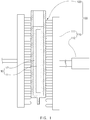
- An electrolyte injection system comprises an electrolyte injection apparatus (not shown) that injects an electrolyte through an opening of a battery in which an electrode assembly and the electrolyte are accommodated and an electrolyte impregnation apparatus 100 that presses the battery cell, into which the electrolyte is injected, to impregnate the electrolyte, which is injected into the battery cell, into the electrode assembly.
- the electrolyte impregnation apparatus 100 presses the battery cell to impregnate the electrolyte into the electrode assembly, there are problems in which the electrolyte is not impregnated up to the inside of the electrode assembly, and particularly, much time for the electrolyte impregnation is spent.
- the electrolyte impregnation apparatus may press the battery cell and simultaneously apply ultrasonic vibration to the battery cell.
- the electrolyte impregnation apparatus may induce the electrolyte so that the electrolyte is forcibly absorbed into the electrode assembly to improve impregnation ability, and particularly, reduce an electrolyte impregnation time.
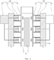
- the electrolyte impregnation apparatus 100 comprises a pressing unit 110 pressing a battery cell 10 in which an electrode assembly 11 and an electrolyte are accommodated and an ultrasonic vibration unit 120 applying ultrasonic vibration to the battery call 10 that is pressed by the pressing unit 110.
- the pressing unit 110 comprises a pressing plate 111 pressing each of both surfaces of the battery cell 10 and a cylinder 112 moving the pressing plate 111 so that the pressing plate 111 presses each of both the surfaces of the battery cell 10.
- a pressing surface of the pressing plate 111 may have a flat plate shape so that the pressing plate 111 presses the surfaces of the battery cell by using the same force.
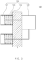
- the ultrasonic vibration unit 120 comprises an ultrasonic vibration element 121 installed on the pressing plate 111 to apply the ultrasonic vibration to the battery cell 10 and an ultrasonic generator 133 applying a voltage to the ultrasonic vibration element 121 to vibrate the ultrasonic vibration element 121.
- the ultrasonic vibration element 121 together with the pressing plate 111 may press the surface of the battery cell 10.
- the ultrasonic vibration element 121 may be vibrated to forcibly vibrate electrolyte injected into the battery cell 10.
- the electrolyte 12 may be permeated and absorbed up to the inside of the electrode assembly 11 by the vibration force to improve the impregnation ability.
- the ultrasonic generator 122 may apply the voltage to one or two or more ultrasonic vibration elements of the plurality of ultrasonic vibration elements 121 to vibrate the ultrasonic vibration elements 121. That is, the plurality of ultrasonic vibration elements 121 may be selectively vibrated to improve efficiency. For example, the ultrasonic generator 122 may apply the voltage to only the ultrasonic vibration element 121 that presses the battery cell 10 to vibrate the ultrasonic vibration element 121. Thus, unnecessary energy may be prevented from being consumed.
- the ultrasonic vibration unit 120 further comprises a fixing member 123 fixing the ultrasonic vibration element 121 to the pressing plate 111.
- the fixing member 123 may stably fix the ultrasonic vibration element 121 to the pressing surface of the pressing plate 111.
- the fixing member 123 may be provided as a spring. That is, the fixing member 123 that is the spring may provide elasticity to the ultrasonic vibration element 121 to allow the ultrasonic vibration element 121 to elastically press the surface of the battery cell 10 and prevent the battery cell 10 from being damaged by the ultrasonic vibration element 121.
- a protection cover 124 having flexibility may be disposed on an outer circumferential surface of the fixing member 123.
- the protection cover 124 protects the fixing member 123 from the outside without restricting the compression force of the fixing member 123.
- the ultrasonic vibration unit 120 may press the battery cell 10 and simultaneously vibrate the battery cell 10 to allow the electrolyte injected into the battery cell 10 to be stably absorbed up to the inside of the electrode assembly 11, thereby improving the impregnation ability.
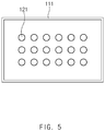
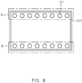
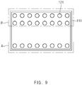
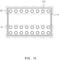
- FIGS. 5 to 11 are views illustrating an arrangement structure of ultrasonic vibration elements according to the present invention.
- an ultrasonic vibration element 121 may be installed on a portion or the whole of a pressing surface of a pressing plate 111.
- the ultrasonic vibration element 121 may be installed on a portion of the pressing surface of the pressing plate 111 according to a size and shape of a battery 10 pressed by the pressing plate 111 to optimize the installation of the ultrasonic vibration element 121.
- an ultrasonic vibration element 121 may be regularly or irregularly installed on a pressing surface of a pressing plate 111.
- the ultrasonic vibration element 121 may be regularly installed to be spaced a predetermined distance from the pressing surface of the pressing plate to uniformly vibrate the entire surface of the battery cell, thereby realizing the uniform impregnation ability on the whole of the electrode assembly.
- the ultrasonic vibration element 121 may be irregularly installed on the pressing surface of the pressing plate 111. Thus, a specific portion of the battery cell may be more strongly vibrated to improve the impregnation ability.
- the ultrasonic vibration unit may be provided with a first vibration group A constituted by a plurality of ultrasonic vibration elements 121a, each of which has a first size, and a second vibration group B constituted by a plurality of ultrasonic vibration elements 121b, each of which has a second size equal to or different from the first size, on a pressing surface of a pressing plate 110. That is, a battery cell may be pressed by the first vibration group A to impregnate an electrolyte, or the battery cell may be pressed by the second vibration group B to impregnate the electrolyte according to a size and shape of the battery cell.
- a first vibration group A may be disposed on one side of a pressing surface of the pressing plate 111, and a second vibration group B may be disposed on the other side of the pressing surface of the pressing plate 111.
- the first vibration group A may be disposed on an upper portion of the pressing plate 111
- the second vibration group B may be arranged on a lower portion of the pressing surface of the pressing plate 111. This is an arranged structure that is used when it is required for improving impregnation ability in upper and lower portions of the battery cell.
- the first vibration group A may be arranged on a left portion of the pressing surface of the pressing plate 111
- the second vibration group B may be arranged on a right portion of the pressing surface of the pressing plate 111.
- the ultrasonic vibration unit may comprise ultrasonic vibration elements 121 in which the number of second vibration group B is greater than that of first vibration group A.
- the second vibration group B and the first vibration group A are respectivley arranged on one side and the other side of a pressing surface of a pressing plate 111.
- the ultrasonic vibration elements 121 of the second vibration group B may be arranged in two rows, and the ultrasonic vibration elements 121 of the first vibration group A may be arranged in one row as illustrated in FIG. 9 .
- the ultrasonic vibration elements of the second vibration group B may be arranged in one row, and the ultrasonic vibration elements of the first vibration group A may be arranged in two rows.
- This structure may be used when it is necessary to apply different ultrasonic vibration areas on one side and the other side of the battery cell.
- ultrasonic vibration elements 121 of the second vibration group B are more densely arranged than those of the first vibration group A.
- the ultrasonic vibration elements 121b of the second vibration group B may be densely arranged so that more ultrasonic vibration elements 121b of the second vibration group B than the ultrasonic vibration elements 121a of the first vibration group A are installed.
- a voltage may be applied to a plurality of ultrasonic vibration elements 121 provided in a first vibration group A through an ultrasonic generator to vibrate the plurality of ultrasonic vibration elements 121, or a voltage may be applied to a plurality of ultrasonic vibration elements 121 provided in a second vibration group B to vibrate the plurality of ultrasonic vibration elements 121. That is, only the ultrasonic vibration elements 121 of the group, by which the battery cell is pressed, may be vibrated to reduce unnecessary energy consumption.
- a voltage may be applied to a portion of a plurality of ultrasonic vibration elements 121 provided in a first vibration group A through an ultrasonic generator to vibrate the portion of the plurality of ultrasonic vibration elements 121, or a voltage may be applied to a portion of a plurality of ultrasonic vibration elements 121 provided in a second vibration group B to vibrate the portion of the plurality of ultrasonic vibration elements 121. That is, only the ultrasonic vibration elements 121, by which a battery cell is pressed, may be vibrated regardless of the groups to reduce unnecessary energy consumption.
- a voltage may be applied to a portion of a plurality of ultrasonic vibration elements 121 provided in a first vibration group A through an ultrasonic generator to vibrate the portion of the plurality of ultrasonic vibration elements 121, and simultaneously, a voltage may be applied to a portion of a plurality of ultrasonic vibration elements 121 provided in a second vibration group B to vibrate the portion of the plurality of ultrasonic vibration elements 121. That is, the ultrasonic vibration elements 121 of the groups A and B, by which the battery cells are actually pressed, may be ultrasonic-vibrated to reduce unnecessary energy consumption.
- the ultrasonic vibration element 121 may be provided as a spring having elastic restoring force. That is, the ultrasonic vibration element 121 may be provided as the spring having the elastic restoring force to adjust a pressure applied to the battery, and particularly, it may be unnecessary to add a separate part having the elastic restoring force.
Landscapes
- Chemical & Material Sciences (AREA)
- Chemical Kinetics & Catalysis (AREA)
- Electrochemistry (AREA)
- General Chemical & Material Sciences (AREA)
- Engineering & Computer Science (AREA)
- Manufacturing & Machinery (AREA)
- Filling, Topping-Up Batteries (AREA)
- Secondary Cells (AREA)
Priority Applications (1)
| Application Number | Priority Date | Filing Date | Title |
|---|---|---|---|
| PL17782586T PL3322002T3 (pl) | 2016-04-15 | 2017-03-22 | Urządzenie do nasączania elektrolitem |
Applications Claiming Priority (2)
| Application Number | Priority Date | Filing Date | Title |
|---|---|---|---|
| KR1020160046250A KR101949973B1 (ko) | 2016-04-15 | 2016-04-15 | 전해액 함침장치 |
| PCT/KR2017/003086 WO2017179831A2 (ko) | 2016-04-15 | 2017-03-22 | 전해액 함침장치 |
Publications (3)
| Publication Number | Publication Date |
|---|---|
| EP3322002A2 true EP3322002A2 (de) | 2018-05-16 |
| EP3322002A4 EP3322002A4 (de) | 2018-07-04 |
| EP3322002B1 EP3322002B1 (de) | 2019-06-19 |
Family
ID=60042659
Family Applications (1)
| Application Number | Title | Priority Date | Filing Date |
|---|---|---|---|
| EP17782586.6A Active EP3322002B1 (de) | 2016-04-15 | 2017-03-22 | Vorrichtung zum befüllen mit elektrolyt |
Country Status (7)
| Country | Link |
|---|---|
| US (1) | US10511011B2 (de) |
| EP (1) | EP3322002B1 (de) |
| JP (1) | JP6628236B2 (de) |
| KR (1) | KR101949973B1 (de) |
| CN (1) | CN108886131B (de) |
| PL (1) | PL3322002T3 (de) |
| WO (1) | WO2017179831A2 (de) |
Cited By (2)
| Publication number | Priority date | Publication date | Assignee | Title |
|---|---|---|---|---|
| EP3699993A4 (de) * | 2018-03-26 | 2021-01-27 | Lg Chem, Ltd. | Verfahren zur herstellung einer beutelartigen sekundärbatterie |
| EP4258401A4 (de) * | 2021-11-23 | 2024-11-27 | LG Energy Solution, Ltd. | Sekundärbatterieaktivierungsvorrichtung und sekundärbatterieherstellungsverfahren damit |
Families Citing this family (4)
| Publication number | Priority date | Publication date | Assignee | Title |
|---|---|---|---|---|
| ES3030487T3 (en) * | 2018-03-26 | 2025-06-30 | Lg Energy Solution Ltd | Method of preparing pouch type secondary battery |
| KR102548344B1 (ko) * | 2019-03-18 | 2023-06-26 | 주식회사 엘지에너지솔루션 | 진동을 이용하는 전지셀 제조용 전해액 함침 장치 및 이를 이용하는 전지셀 제조방법 |
| CN110335985A (zh) * | 2019-07-08 | 2019-10-15 | 江苏烨晨智能科技有限公司 | 一种振动式ev电池注液装置 |
| KR102798481B1 (ko) * | 2020-01-10 | 2025-04-22 | 주식회사 엘지에너지솔루션 | 가스 트랩 제거를 위한 가압 지그 및 이를 이용한 이차전지의 제조방법 |
Family Cites Families (18)
| Publication number | Priority date | Publication date | Assignee | Title |
|---|---|---|---|---|
| GB1385910A (en) * | 1971-05-15 | 1975-03-05 | Lucas Industries Ltd | Metal-air cells |
| US3734805A (en) * | 1971-07-27 | 1973-05-22 | Branson Instr | Ultrasonic sewing machine |
| JPS63224158A (ja) * | 1987-03-11 | 1988-09-19 | Japan Storage Battery Co Ltd | 密閉形蓄電池の注液方法 |
| JPH08273659A (ja) * | 1995-04-03 | 1996-10-18 | Toshiba Corp | 電解液含浸方法およびその装置 |
| KR19990055239A (ko) | 1997-12-27 | 1999-07-15 | 전주범 | 전지의 에이징 방법 |
| KR20000025359A (ko) * | 1998-10-10 | 2000-05-06 | 홍건희 | 리튬이온 폴리머전지 전해질 함침장치 |
| US6465121B1 (en) * | 2000-08-30 | 2002-10-15 | Lev M. Dawson | Method for distributing electrolyte in batteries |
| KR100958649B1 (ko) | 2002-12-27 | 2010-05-20 | 삼성에스디아이 주식회사 | 전지부와, 이의 감는 방법과, 이를 채용하여 제조된 리튬이차 전지 |
| KR101300591B1 (ko) * | 2010-09-30 | 2013-08-27 | 주식회사 엘지화학 | 이차 전지의 전해액 함침 증진 장치 및 방법 |
| DE102010052397A1 (de) * | 2010-11-24 | 2012-05-24 | Li-Tec Battery Gmbh | Verfahren und Vorrichtung zum Befüllen einer elektrochemischen Zelle |
| WO2012165862A2 (ko) * | 2011-05-30 | 2012-12-06 | 주식회사 엘지화학 | 초음파 용접 장치 및 전극 구조체 강도를 개선한 이차 전지 |
| US11546787B2 (en) * | 2012-05-09 | 2023-01-03 | Samsung Electronics Co., Ltd. | CSI definitions and feedback modes for coordinated multi-point transmission |
| DE112012006588T5 (de) | 2012-06-28 | 2015-04-02 | Toyota Jidosha Kabushiki Kaisha | Verfahren zur Herstellung einer Batterie und Batterie |
| KR20140018014A (ko) * | 2012-08-03 | 2014-02-12 | 에스케이이노베이션 주식회사 | 파우치형 이차전지의 제조방법 |
| CN104584306A (zh) * | 2012-11-08 | 2015-04-29 | 株式会社Lg化学 | 二次电池的制造方法 |
| KR101416814B1 (ko) | 2012-12-31 | 2014-07-14 | 비나텍주식회사 | 전해액 함침장치, 이를 이용한 슈퍼 커패시터 제조시스템 및 제조방법 |
| JP2015032503A (ja) * | 2013-08-05 | 2015-02-16 | トヨタ自動車株式会社 | 角型リチウムイオン二次電池における電解液の注入方法 |
| KR101747909B1 (ko) * | 2014-02-13 | 2017-06-15 | 주식회사 엘지화학 | 전해액 함침 장치 |
-
2016
- 2016-04-15 KR KR1020160046250A patent/KR101949973B1/ko active Active
-
2017
- 2017-03-22 US US15/743,814 patent/US10511011B2/en active Active
- 2017-03-22 PL PL17782586T patent/PL3322002T3/pl unknown
- 2017-03-22 EP EP17782586.6A patent/EP3322002B1/de active Active
- 2017-03-22 WO PCT/KR2017/003086 patent/WO2017179831A2/ko not_active Ceased
- 2017-03-22 CN CN201780002544.3A patent/CN108886131B/zh active Active
- 2017-03-22 JP JP2018514339A patent/JP6628236B2/ja active Active
Cited By (3)
| Publication number | Priority date | Publication date | Assignee | Title |
|---|---|---|---|---|
| EP3699993A4 (de) * | 2018-03-26 | 2021-01-27 | Lg Chem, Ltd. | Verfahren zur herstellung einer beutelartigen sekundärbatterie |
| US11114698B2 (en) | 2018-03-26 | 2021-09-07 | Lg Chem, Ltd. | Method of preparing pouch type secondary battery |
| EP4258401A4 (de) * | 2021-11-23 | 2024-11-27 | LG Energy Solution, Ltd. | Sekundärbatterieaktivierungsvorrichtung und sekundärbatterieherstellungsverfahren damit |
Also Published As
| Publication number | Publication date |
|---|---|
| CN108886131B (zh) | 2021-03-16 |
| WO2017179831A2 (ko) | 2017-10-19 |
| KR20170118452A (ko) | 2017-10-25 |
| US20180198111A1 (en) | 2018-07-12 |
| KR101949973B1 (ko) | 2019-02-20 |
| WO2017179831A3 (ko) | 2018-04-05 |
| EP3322002B1 (de) | 2019-06-19 |
| US10511011B2 (en) | 2019-12-17 |
| JP6628236B2 (ja) | 2020-01-08 |
| PL3322002T3 (pl) | 2019-12-31 |
| EP3322002A4 (de) | 2018-07-04 |
| CN108886131A (zh) | 2018-11-23 |
| JP2018527722A (ja) | 2018-09-20 |
Similar Documents
| Publication | Publication Date | Title |
|---|---|---|
| US10511011B2 (en) | Electrolyte impregnation apparatus | |
| US10992000B2 (en) | Method for manufacturing battery module | |
| US9680178B2 (en) | Restraining of battery cells by way of a cambered design of the battery housing | |
| US20200343607A1 (en) | Battery Module, Battery Pack Including Battery Module, And Vehicle Including Battery Pack | |
| US10483502B2 (en) | Battery cell having anti-wrinkle member | |
| PL2122724T3 (pl) | Spoiwo do elektrody w układzie elektrochemicznym, elektroda zawierająca to spoiwo i układ elektrochemiczny zawierający tę elektrodę | |
| KR102123661B1 (ko) | 배터리 팩 및 이러한 배터리 팩을 포함하는 자동차 | |
| JP2019114477A (ja) | 電池モジュール | |
| US11870089B2 (en) | Battery cell pack | |
| WO2008142535A3 (en) | Mobile unit having fuel cell | |
| US10553839B2 (en) | Battery case, battery module, and battery module manufacturing method | |
| AU2016420289A1 (en) | Frame body, cell frame, cell stack, and redox flow battery | |
| US20180366705A1 (en) | Battery pack case and method for manufacturing the same | |
| EP3067978A1 (de) | Flexible batteriezelle | |
| CN209979684U (zh) | 圆柱电池测试装置 | |
| WO2013075843A8 (de) | Zellkontaktieranordnung für einen energiespeicher | |
| JP2020068103A (ja) | 二次電池 | |
| KR20200075688A (ko) | 배터리 모듈, 이러한 배터리 모듈을 포함하는 배터리 팩과 이러한 배터리 팩을 포함하는 자동차, 및 이러한 배터리 모듈의 제조 방법 | |
| EP4358213A1 (de) | Batteriezellenandruckspannvorrichtung | |
| KR102255495B1 (ko) | 배터리 모듈, 이를 포함하는 배터리 팩 및 자동차 | |
| CN216389485U (zh) | 一种锂离子电池模组 | |
| KR20250062316A (ko) | 전해액 주입구용 밀폐 부재, 이를 포함하는 배터리 캡 어셈블리 및 배터리 셀 | |
| KR101767671B1 (ko) | 셀 케이스의 내면에 주름 방지용 부재가 부가되어 있는 전지셀 | |
| KR20240060375A (ko) | 원통형 이차 전지 및 이의 제조 방법 | |
| CN210403917U (zh) | 一种燃料电池电堆固定装置 |
Legal Events
| Date | Code | Title | Description |
|---|---|---|---|
| STAA | Information on the status of an ep patent application or granted ep patent |
Free format text: STATUS: THE INTERNATIONAL PUBLICATION HAS BEEN MADE |
|
| PUAI | Public reference made under article 153(3) epc to a published international application that has entered the european phase |
Free format text: ORIGINAL CODE: 0009012 |
|
| STAA | Information on the status of an ep patent application or granted ep patent |
Free format text: STATUS: REQUEST FOR EXAMINATION WAS MADE |
|
| 17P | Request for examination filed |
Effective date: 20180110 |
|
| AK | Designated contracting states |
Kind code of ref document: A2 Designated state(s): AL AT BE BG CH CY CZ DE DK EE ES FI FR GB GR HR HU IE IS IT LI LT LU LV MC MK MT NL NO PL PT RO RS SE SI SK SM TR |
|
| AX | Request for extension of the european patent |
Extension state: BA ME |
|
| A4 | Supplementary search report drawn up and despatched |
Effective date: 20180605 |
|
| RIC1 | Information provided on ipc code assigned before grant |
Ipc: H01M 2/36 20060101AFI20180529BHEP |
|
| GRAP | Despatch of communication of intention to grant a patent |
Free format text: ORIGINAL CODE: EPIDOSNIGR1 |
|
| STAA | Information on the status of an ep patent application or granted ep patent |
Free format text: STATUS: GRANT OF PATENT IS INTENDED |
|
| RIC1 | Information provided on ipc code assigned before grant |
Ipc: H01M 2/36 20060101AFI20190125BHEP |
|
| INTG | Intention to grant announced |
Effective date: 20190218 |
|
| GRAS | Grant fee paid |
Free format text: ORIGINAL CODE: EPIDOSNIGR3 |
|
| GRAA | (expected) grant |
Free format text: ORIGINAL CODE: 0009210 |
|
| STAA | Information on the status of an ep patent application or granted ep patent |
Free format text: STATUS: THE PATENT HAS BEEN GRANTED |
|
| DAV | Request for validation of the european patent (deleted) | ||
| DAX | Request for extension of the european patent (deleted) | ||
| AK | Designated contracting states |
Kind code of ref document: B1 Designated state(s): AL AT BE BG CH CY CZ DE DK EE ES FI FR GB GR HR HU IE IS IT LI LT LU LV MC MK MT NL NO PL PT RO RS SE SI SK SM TR |
|
| REG | Reference to a national code |
Ref country code: GB Ref legal event code: FG4D |
|
| REG | Reference to a national code |
Ref country code: CH Ref legal event code: EP |
|
| REG | Reference to a national code |
Ref country code: IE Ref legal event code: FG4D |
|
| REG | Reference to a national code |
Ref country code: DE Ref legal event code: R096 Ref document number: 602017004709 Country of ref document: DE |
|
| REG | Reference to a national code |
Ref country code: AT Ref legal event code: REF Ref document number: 1146649 Country of ref document: AT Kind code of ref document: T Effective date: 20190715 |
|
| REG | Reference to a national code |
Ref country code: NL Ref legal event code: MP Effective date: 20190619 |
|
| PG25 | Lapsed in a contracting state [announced via postgrant information from national office to epo] |
Ref country code: FI Free format text: LAPSE BECAUSE OF FAILURE TO SUBMIT A TRANSLATION OF THE DESCRIPTION OR TO PAY THE FEE WITHIN THE PRESCRIBED TIME-LIMIT Effective date: 20190619 Ref country code: NO Free format text: LAPSE BECAUSE OF FAILURE TO SUBMIT A TRANSLATION OF THE DESCRIPTION OR TO PAY THE FEE WITHIN THE PRESCRIBED TIME-LIMIT Effective date: 20190919 Ref country code: LT Free format text: LAPSE BECAUSE OF FAILURE TO SUBMIT A TRANSLATION OF THE DESCRIPTION OR TO PAY THE FEE WITHIN THE PRESCRIBED TIME-LIMIT Effective date: 20190619 Ref country code: HR Free format text: LAPSE BECAUSE OF FAILURE TO SUBMIT A TRANSLATION OF THE DESCRIPTION OR TO PAY THE FEE WITHIN THE PRESCRIBED TIME-LIMIT Effective date: 20190619 Ref country code: SE Free format text: LAPSE BECAUSE OF FAILURE TO SUBMIT A TRANSLATION OF THE DESCRIPTION OR TO PAY THE FEE WITHIN THE PRESCRIBED TIME-LIMIT Effective date: 20190619 Ref country code: AL Free format text: LAPSE BECAUSE OF FAILURE TO SUBMIT A TRANSLATION OF THE DESCRIPTION OR TO PAY THE FEE WITHIN THE PRESCRIBED TIME-LIMIT Effective date: 20190619 |
|
| REG | Reference to a national code |
Ref country code: LT Ref legal event code: MG4D |
|
| PG25 | Lapsed in a contracting state [announced via postgrant information from national office to epo] |
Ref country code: GR Free format text: LAPSE BECAUSE OF FAILURE TO SUBMIT A TRANSLATION OF THE DESCRIPTION OR TO PAY THE FEE WITHIN THE PRESCRIBED TIME-LIMIT Effective date: 20190920 Ref country code: LV Free format text: LAPSE BECAUSE OF FAILURE TO SUBMIT A TRANSLATION OF THE DESCRIPTION OR TO PAY THE FEE WITHIN THE PRESCRIBED TIME-LIMIT Effective date: 20190619 Ref country code: RS Free format text: LAPSE BECAUSE OF FAILURE TO SUBMIT A TRANSLATION OF THE DESCRIPTION OR TO PAY THE FEE WITHIN THE PRESCRIBED TIME-LIMIT Effective date: 20190619 Ref country code: BG Free format text: LAPSE BECAUSE OF FAILURE TO SUBMIT A TRANSLATION OF THE DESCRIPTION OR TO PAY THE FEE WITHIN THE PRESCRIBED TIME-LIMIT Effective date: 20190919 |
|
| REG | Reference to a national code |
Ref country code: AT Ref legal event code: MK05 Ref document number: 1146649 Country of ref document: AT Kind code of ref document: T Effective date: 20190619 |
|
| PG25 | Lapsed in a contracting state [announced via postgrant information from national office to epo] |
Ref country code: CZ Free format text: LAPSE BECAUSE OF FAILURE TO SUBMIT A TRANSLATION OF THE DESCRIPTION OR TO PAY THE FEE WITHIN THE PRESCRIBED TIME-LIMIT Effective date: 20190619 Ref country code: SK Free format text: LAPSE BECAUSE OF FAILURE TO SUBMIT A TRANSLATION OF THE DESCRIPTION OR TO PAY THE FEE WITHIN THE PRESCRIBED TIME-LIMIT Effective date: 20190619 Ref country code: NL Free format text: LAPSE BECAUSE OF FAILURE TO SUBMIT A TRANSLATION OF THE DESCRIPTION OR TO PAY THE FEE WITHIN THE PRESCRIBED TIME-LIMIT Effective date: 20190619 Ref country code: EE Free format text: LAPSE BECAUSE OF FAILURE TO SUBMIT A TRANSLATION OF THE DESCRIPTION OR TO PAY THE FEE WITHIN THE PRESCRIBED TIME-LIMIT Effective date: 20190619 Ref country code: AT Free format text: LAPSE BECAUSE OF FAILURE TO SUBMIT A TRANSLATION OF THE DESCRIPTION OR TO PAY THE FEE WITHIN THE PRESCRIBED TIME-LIMIT Effective date: 20190619 Ref country code: PT Free format text: LAPSE BECAUSE OF FAILURE TO SUBMIT A TRANSLATION OF THE DESCRIPTION OR TO PAY THE FEE WITHIN THE PRESCRIBED TIME-LIMIT Effective date: 20191021 Ref country code: RO Free format text: LAPSE BECAUSE OF FAILURE TO SUBMIT A TRANSLATION OF THE DESCRIPTION OR TO PAY THE FEE WITHIN THE PRESCRIBED TIME-LIMIT Effective date: 20190619 |
|
| PG25 | Lapsed in a contracting state [announced via postgrant information from national office to epo] |
Ref country code: ES Free format text: LAPSE BECAUSE OF FAILURE TO SUBMIT A TRANSLATION OF THE DESCRIPTION OR TO PAY THE FEE WITHIN THE PRESCRIBED TIME-LIMIT Effective date: 20190619 Ref country code: SM Free format text: LAPSE BECAUSE OF FAILURE TO SUBMIT A TRANSLATION OF THE DESCRIPTION OR TO PAY THE FEE WITHIN THE PRESCRIBED TIME-LIMIT Effective date: 20190619 Ref country code: IT Free format text: LAPSE BECAUSE OF FAILURE TO SUBMIT A TRANSLATION OF THE DESCRIPTION OR TO PAY THE FEE WITHIN THE PRESCRIBED TIME-LIMIT Effective date: 20190619 Ref country code: IS Free format text: LAPSE BECAUSE OF FAILURE TO SUBMIT A TRANSLATION OF THE DESCRIPTION OR TO PAY THE FEE WITHIN THE PRESCRIBED TIME-LIMIT Effective date: 20191019 |
|
| PG25 | Lapsed in a contracting state [announced via postgrant information from national office to epo] |
Ref country code: TR Free format text: LAPSE BECAUSE OF FAILURE TO SUBMIT A TRANSLATION OF THE DESCRIPTION OR TO PAY THE FEE WITHIN THE PRESCRIBED TIME-LIMIT Effective date: 20190619 |
|
| PG25 | Lapsed in a contracting state [announced via postgrant information from national office to epo] |
Ref country code: DK Free format text: LAPSE BECAUSE OF FAILURE TO SUBMIT A TRANSLATION OF THE DESCRIPTION OR TO PAY THE FEE WITHIN THE PRESCRIBED TIME-LIMIT Effective date: 20190619 |
|
| PG25 | Lapsed in a contracting state [announced via postgrant information from national office to epo] |
Ref country code: IS Free format text: LAPSE BECAUSE OF FAILURE TO SUBMIT A TRANSLATION OF THE DESCRIPTION OR TO PAY THE FEE WITHIN THE PRESCRIBED TIME-LIMIT Effective date: 20200224 |
|
| REG | Reference to a national code |
Ref country code: DE Ref legal event code: R097 Ref document number: 602017004709 Country of ref document: DE |
|
| PLBE | No opposition filed within time limit |
Free format text: ORIGINAL CODE: 0009261 |
|
| STAA | Information on the status of an ep patent application or granted ep patent |
Free format text: STATUS: NO OPPOSITION FILED WITHIN TIME LIMIT |
|
| PG2D | Information on lapse in contracting state deleted |
Ref country code: IS |
|
| 26N | No opposition filed |
Effective date: 20200603 |
|
| PG25 | Lapsed in a contracting state [announced via postgrant information from national office to epo] |
Ref country code: SI Free format text: LAPSE BECAUSE OF FAILURE TO SUBMIT A TRANSLATION OF THE DESCRIPTION OR TO PAY THE FEE WITHIN THE PRESCRIBED TIME-LIMIT Effective date: 20190619 |
|
| PG25 | Lapsed in a contracting state [announced via postgrant information from national office to epo] |
Ref country code: MC Free format text: LAPSE BECAUSE OF FAILURE TO SUBMIT A TRANSLATION OF THE DESCRIPTION OR TO PAY THE FEE WITHIN THE PRESCRIBED TIME-LIMIT Effective date: 20190619 |
|
| REG | Reference to a national code |
Ref country code: CH Ref legal event code: PL |
|
| REG | Reference to a national code |
Ref country code: DE Ref legal event code: R079 Ref document number: 602017004709 Country of ref document: DE Free format text: PREVIOUS MAIN CLASS: H01M0002360000 Ipc: H01M0050600000 |
|
| REG | Reference to a national code |
Ref country code: BE Ref legal event code: MM Effective date: 20200331 |
|
| PG25 | Lapsed in a contracting state [announced via postgrant information from national office to epo] |
Ref country code: LU Free format text: LAPSE BECAUSE OF NON-PAYMENT OF DUE FEES Effective date: 20200322 |
|
| PG25 | Lapsed in a contracting state [announced via postgrant information from national office to epo] |
Ref country code: CH Free format text: LAPSE BECAUSE OF NON-PAYMENT OF DUE FEES Effective date: 20200331 Ref country code: LI Free format text: LAPSE BECAUSE OF NON-PAYMENT OF DUE FEES Effective date: 20200331 Ref country code: IE Free format text: LAPSE BECAUSE OF NON-PAYMENT OF DUE FEES Effective date: 20200322 |
|
| PG25 | Lapsed in a contracting state [announced via postgrant information from national office to epo] |
Ref country code: BE Free format text: LAPSE BECAUSE OF NON-PAYMENT OF DUE FEES Effective date: 20200331 |
|
| PG25 | Lapsed in a contracting state [announced via postgrant information from national office to epo] |
Ref country code: MT Free format text: LAPSE BECAUSE OF FAILURE TO SUBMIT A TRANSLATION OF THE DESCRIPTION OR TO PAY THE FEE WITHIN THE PRESCRIBED TIME-LIMIT Effective date: 20190619 Ref country code: CY Free format text: LAPSE BECAUSE OF FAILURE TO SUBMIT A TRANSLATION OF THE DESCRIPTION OR TO PAY THE FEE WITHIN THE PRESCRIBED TIME-LIMIT Effective date: 20190619 |
|
| PG25 | Lapsed in a contracting state [announced via postgrant information from national office to epo] |
Ref country code: MK Free format text: LAPSE BECAUSE OF FAILURE TO SUBMIT A TRANSLATION OF THE DESCRIPTION OR TO PAY THE FEE WITHIN THE PRESCRIBED TIME-LIMIT Effective date: 20190619 |
|
| P01 | Opt-out of the competence of the unified patent court (upc) registered |
Effective date: 20230512 |
|
| REG | Reference to a national code |
Ref country code: DE Ref legal event code: R081 Ref document number: 602017004709 Country of ref document: DE Owner name: LG ENERGY SOLUTION, LTD., KR Free format text: FORMER OWNER: LG CHEM, LTD., SEOUL, KR |
|
| REG | Reference to a national code |
Ref country code: GB Ref legal event code: 732E Free format text: REGISTERED BETWEEN 20230824 AND 20230831 |
|
| PGFP | Annual fee paid to national office [announced via postgrant information from national office to epo] |
Ref country code: GB Payment date: 20260224 Year of fee payment: 10 |
|
| PGFP | Annual fee paid to national office [announced via postgrant information from national office to epo] |
Ref country code: DE Payment date: 20260220 Year of fee payment: 10 |
|
| PGFP | Annual fee paid to national office [announced via postgrant information from national office to epo] |
Ref country code: FR Payment date: 20260224 Year of fee payment: 10 |
|
| PGFP | Annual fee paid to national office [announced via postgrant information from national office to epo] |
Ref country code: PL Payment date: 20260224 Year of fee payment: 10 |