EP3322060B1 - Verfahren zur dämpfung elektromechanischer schwingungen auf einem stromversorgungssystem - Google Patents
Verfahren zur dämpfung elektromechanischer schwingungen auf einem stromversorgungssystem Download PDFInfo
- Publication number
- EP3322060B1 EP3322060B1 EP16198705.2A EP16198705A EP3322060B1 EP 3322060 B1 EP3322060 B1 EP 3322060B1 EP 16198705 A EP16198705 A EP 16198705A EP 3322060 B1 EP3322060 B1 EP 3322060B1
- Authority
- EP
- European Patent Office
- Prior art keywords
- reactive power
- power
- value
- oscillation
- damping
- Prior art date
- Legal status (The legal status is an assumption and is not a legal conclusion. Google has not performed a legal analysis and makes no representation as to the accuracy of the status listed.)
- Active
Links
Images


Classifications
-
- H—ELECTRICITY
- H02—GENERATION; CONVERSION OR DISTRIBUTION OF ELECTRIC POWER
- H02J—ELECTRIC POWER NETWORKS; CIRCUIT ARRANGEMENTS OR SYSTEMS FOR SUPPLYING OR DISTRIBUTING ELECTRIC POWER; SYSTEMS FOR STORING ELECTRIC ENERGY
- H02J3/00—Circuit arrangements for AC mains or AC distribution networks
- H02J3/001—Arrangements for handling faults or abnormalities, e.g. emergencies or contingencies
- H02J3/0014—Arrangements for handling faults or abnormalities, e.g. emergencies or contingencies for preventing or reducing power oscillations in networks
-
- F—MECHANICAL ENGINEERING; LIGHTING; HEATING; WEAPONS; BLASTING
- F03—MACHINES OR ENGINES FOR LIQUIDS; WIND, SPRING, OR WEIGHT MOTORS; PRODUCING MECHANICAL POWER OR A REACTIVE PROPULSIVE THRUST, NOT OTHERWISE PROVIDED FOR
- F03D—WIND MOTORS
- F03D7/00—Controlling wind motors
- F03D7/02—Controlling wind motors the wind motors having rotation axis substantially parallel to the air flow entering the rotor
- F03D7/0296—Controlling wind motors the wind motors having rotation axis substantially parallel to the air flow entering the rotor to prevent, counteract or reduce noise emissions
-
- F—MECHANICAL ENGINEERING; LIGHTING; HEATING; WEAPONS; BLASTING
- F03—MACHINES OR ENGINES FOR LIQUIDS; WIND, SPRING, OR WEIGHT MOTORS; PRODUCING MECHANICAL POWER OR A REACTIVE PROPULSIVE THRUST, NOT OTHERWISE PROVIDED FOR
- F03D—WIND MOTORS
- F03D7/00—Controlling wind motors
- F03D7/02—Controlling wind motors the wind motors having rotation axis substantially parallel to the air flow entering the rotor
- F03D7/04—Automatic control; Regulation
- F03D7/042—Automatic control; Regulation by means of an electrical or electronic controller
- F03D7/048—Automatic control; Regulation by means of an electrical or electronic controller controlling wind farms
-
- H—ELECTRICITY
- H02—GENERATION; CONVERSION OR DISTRIBUTION OF ELECTRIC POWER
- H02J—ELECTRIC POWER NETWORKS; CIRCUIT ARRANGEMENTS OR SYSTEMS FOR SUPPLYING OR DISTRIBUTING ELECTRIC POWER; SYSTEMS FOR STORING ELECTRIC ENERGY
- H02J3/00—Circuit arrangements for AC mains or AC distribution networks
- H02J3/001—Arrangements for handling faults or abnormalities, e.g. emergencies or contingencies
- H02J3/0014—Arrangements for handling faults or abnormalities, e.g. emergencies or contingencies for preventing or reducing power oscillations in networks
- H02J3/00142—Oscillations concerning frequency
-
- H—ELECTRICITY
- H02—GENERATION; CONVERSION OR DISTRIBUTION OF ELECTRIC POWER
- H02J—ELECTRIC POWER NETWORKS; CIRCUIT ARRANGEMENTS OR SYSTEMS FOR SUPPLYING OR DISTRIBUTING ELECTRIC POWER; SYSTEMS FOR STORING ELECTRIC ENERGY
- H02J3/00—Circuit arrangements for AC mains or AC distribution networks
- H02J3/18—Arrangements for adjusting, eliminating or compensating reactive power in networks
-
- F—MECHANICAL ENGINEERING; LIGHTING; HEATING; WEAPONS; BLASTING
- F05—INDEXING SCHEMES RELATING TO ENGINES OR PUMPS IN VARIOUS SUBCLASSES OF CLASSES F01-F04
- F05B—INDEXING SCHEME RELATING TO WIND, SPRING, WEIGHT, INERTIA OR LIKE MOTORS, TO MACHINES OR ENGINES FOR LIQUIDS COVERED BY SUBCLASSES F03B, F03D AND F03G
- F05B2220/00—Application
- F05B2220/70—Application in combination with
- F05B2220/706—Application in combination with an electrical generator
-
- Y—GENERAL TAGGING OF NEW TECHNOLOGICAL DEVELOPMENTS; GENERAL TAGGING OF CROSS-SECTIONAL TECHNOLOGIES SPANNING OVER SEVERAL SECTIONS OF THE IPC; TECHNICAL SUBJECTS COVERED BY FORMER USPC CROSS-REFERENCE ART COLLECTIONS [XRACs] AND DIGESTS
- Y02—TECHNOLOGIES OR APPLICATIONS FOR MITIGATION OR ADAPTATION AGAINST CLIMATE CHANGE
- Y02E—REDUCTION OF GREENHOUSE GAS [GHG] EMISSIONS, RELATED TO ENERGY GENERATION, TRANSMISSION OR DISTRIBUTION
- Y02E10/00—Energy generation through renewable energy sources
- Y02E10/70—Wind energy
- Y02E10/72—Wind turbines with rotation axis in wind direction
-
- Y—GENERAL TAGGING OF NEW TECHNOLOGICAL DEVELOPMENTS; GENERAL TAGGING OF CROSS-SECTIONAL TECHNOLOGIES SPANNING OVER SEVERAL SECTIONS OF THE IPC; TECHNICAL SUBJECTS COVERED BY FORMER USPC CROSS-REFERENCE ART COLLECTIONS [XRACs] AND DIGESTS
- Y02—TECHNOLOGIES OR APPLICATIONS FOR MITIGATION OR ADAPTATION AGAINST CLIMATE CHANGE
- Y02E—REDUCTION OF GREENHOUSE GAS [GHG] EMISSIONS, RELATED TO ENERGY GENERATION, TRANSMISSION OR DISTRIBUTION
- Y02E10/00—Energy generation through renewable energy sources
- Y02E10/70—Wind energy
- Y02E10/76—Power conversion electric or electronic aspects
Definitions
- the present invention pertains to a method of damping electromechanical oscillations on a power system and to a wind farm adapted to provide damping of electromechanical oscillations on the power system.
- power system is used in the meaning of power grid as well as the term system voltage is used as synonym for grid voltage.
- system voltage is used as synonym for grid voltage.
- wind energy turbine and wind farm stand for wind turbine generator (WTG) and wind power plant (WP), respectively.
- WO 2013/004252 A2 relates to a method for damping system oscillations.
- the oscillations may be damped by controlling e.g. wind turbine generators to inject power to the system in anti-phase with the system oscillations.
- a plurality of wind turbine generators is controlled so that each of them only generates a part of the anti-phase power signal while all of the wind turbine generators in combination generate the entire anti-phase power signal.
- For damping of the system oscillations always at least two reference signals are determined for two different power generator units.
- EP 2 499 714 A2 discloses a wind turbine for controlling power oscillations on a system of a power system.
- the wind turbine comprises rotor blades for turning by the wind, an electric generator rotatably coupled to the rotor blades, a power converter responsive to an electricity generated by the electric generator, the power converter for converting the generated electricity to a frequency and a voltage suitable for supply to the power system, and a power converter for regulating voltage on the system supplemented by modulating real power for damping the power oscillations.
- the power converter regulates at least the system voltage based on the real power for damping.
- power oscillation damping for inter-area power oscillations is done by so-called STATCOM devices modulating the voltage at the point of interconnection. It is known that inter-area power occur on transmission systems with long lines and large physical distances between major generation sources. Typically, after a disturbance, groups of generators in a first geographic region swing against another group of generators in a second geographic region separated from the first region by a series of long transmission lines. Naturally, these oscillations are of a very low frequency (typically between 0.1 Hz and 0.7 Hz) and are poorly damped in the absence of supplemental damping.
- US 8,618,694 B2 discloses a method for damping oscillations of the electrical power on a power system.
- a controller is configured to generate a first control signal to cause an inverter of the first wind turbine to modulate the electrical power output by the first wind turbine for damping oscillations of one frequency in electrical power on the power system and to generate a second control signal to control the inverter of the second wind turbine to modulate the electrical power output by the second wind turbine for damping oscillations of a different frequency in the electrical power on the power system.
- EP 2 516 164 A2 and US 2016/0141991 A1 refer to sub synchronous resonance (SSR) oscillations in the power system.
- SSR oscillations occur when the electric power system exchanges energy with the turbine generator at one or more frequencies below the electrical system synchronous frequency. Usually two frequencies have to be considered. Taking a 60 Hz system a supersynchronous frequency may occur at roughly about 70 Hz, while the SSR frequency is at about 10 Hz. Usually the supersynchronous frequency is damped by mechanical system components while the subsynchronous frequency at about 10 Hz requires additional damping.
- EP 2 594 004 B1 refers to inter-area oscillations which typically occur in large interconnected power systems with two or more areas interconnected through relatively weak alternating current (AC) transmission lines. If a power oscillation between two areas of a power system is excited the rotor angles of synchronous machines in one area will start to oscillate in counter phase with synchronous machines in the other area and thereby force a flow of active power back and forth between the areas.
- a device controller changes the rotational speed reference of the mechanical system of the power generator in order to extract or deposit energy from the electrical output power of the converter device. Therefore, the electrical output power is modulated to damp the power oscillations.
- US 2010/0109447 A1 refers to a wide area transmission control of wind farms wherein the dynamic and voltage stability of utility transmission systems is improved by a coordinated control. Electrical measurements of the system including synchronized phasors are supplied to one or more wind farm controllers which in turn perform a regulation function improving the damping of electromechanical oscillations or voltage performance in the utility system.
- the control structure is of a decentralized nature.
- the technical problem of the invention is to provide a method as well as a wind farm for an improved damping of electromechanical oscillations on the power system.
- a method of damping electromechanical oscillations on a power system is provided.
- the damping in form of attenuation takes place by injecting reactive power generated by one or more wind energy turbines into the power system.
- One important aspect of the reactive power controller is to stabilize the system voltage by injecting reactive power.
- the method according to the invention comprises measuring oscillation data associated with the power system. The measured oscillation data is filtered to remove a steady state offset from the data.
- the method according to the invention furthermore comprises a step of determining a frequency value and an amplitude value from the filtered oscillation data and triggering damping if the frequency value of the filtered oscillation data falls within a predetermined frequency interval and/or the amplitude value of the filtered oscillation data exceeds a predetermined threshold value. If damping of the electromechanical oscillations on the power system was triggered the damping of the oscillation data is controlled to compensate a gain and a delay caused by the reactive power controller to the reference reactive power value. Therefore, triggering the damping compensates the delay of the injected reactive power control loop.
- the method of damping electromechanical oscillations uses a frequency value and/or an amplitude value to detect the electromechanical oscillations and switch the damping on.
- the damping according the invention is sometimes referred to as a switchable damping, because of its triggering step.
- the advantage of the switchable damping for electromechanical oscillations is that any interference with controller dynamics during normal operations is avoided. In particular, those parts of the controller dynamics governed by requirements of a grid code are unchanged as long as the measured oscillation data do not indicate any electromechanical oscillations.
- the terms "falls within” or “falling within” are referring to a quantity determined as being within a certain frequency interval.
- the continuous power oscillation damping comprises the steps of correcting a gain and a shift in the filtered oscillation data. These oscillation data are provided as corrected oscillation data.
- the correction of the corrected oscillation data achieves to compensate a gain and a delay of the reference reactive power value as caused by the reactive power controller.
- a reactive power setpoint is provided based on the corrected reference reactive power value and the difference between the oscillation data and the corrected oscillation data.
- the last step compensates the influence of the electromechanical oscillations in the reference reactive power value.
- the measured oscillation data correspond to the actual system voltage or to the reference reactive power value as determined by the active power controller depending on the actual system voltage.
- the desired damping of electromechanical oscillations both values are equally suited to determine an amount of reactive power to the system which achieves a suitable damping.
- the measured oscillation data is preferably band pass filtered in order to eliminate any influence on frequencies higher and/or lower than frequencies of the electromechanical oscillations on the damping.
- the frequencies higher and/or lower than the frequencies of the electromechanical oscillations do not contribute to the dynamic behavior.
- the band pass filter may also be a band-stop filter.
- the predetermined frequency interval used to detect electromechanical oscillations lies between 0.2 Hz and 1.5 Hz.
- the predetermined frequency interval may be chosen to be 0.5 Hz to 1.1 Hz and more preferably between 0.6 Hz and 1.0 Hz can be sufficient.
- a 2 nd -order lag element For processing the oscillation data preferably after filtering a 2 nd -order lag element is used.
- the 2 nd -order lag element is in the following also called PT2-element.
- the behavior of the 2 nd -order lag element has proven in particular suited to compensate the system dynamics and in particular the dynamic behavior of the reactive power controller.
- the parameters of the PT2-element are dependent on at least one of the following data: frequency, gain, phase and amplitude.
- the amplitude may be omitted, however the amplitude can be used to provide more flexibility to the 2 nd -order lag element in modelling a gain.
- Each of these values, in particular, all of these values help to define a suitable PT2-element providing the right attenuation and phase shift to the measured oscillation data.
- the inventive wind farm is connected to the power system.
- the wind farm comprises a plurality of wind energy turbines.
- the wind farm comprises a wind farm controller arranged to output setpoints for active power and for reactive power to each of the wind energy turbines.
- the wind farm further comprises a measurement device for measuring oscillation data on the power system.
- Each of the wind energy turbines comprises a power generator driven by a wind rotor and a converter adapted to provide active power and reactive power to a power system.
- a reactive power controller for providing a reference reactive power value depending on the actual system value is provided.
- the actual system value is the actual system voltage.
- a filter unit is been comprised within the farm controller.
- the filter unit can be a software part of the reactive power controller or a separate hardware element.
- the filter unit is adapted to remove a steady state offset from the oscillation data.
- a power oscillation damping device (POD-device) is additionally comprised within the farm controller.
- the POD-device is arranged for damping oscillation data in order to compensate a gain and a delay applied to the reference reactive power value by the reactive power controller.
- the delay of the reference reactive power value corresponds to a delay in the injected reactive power.
- the farm controller is adapted to output a reactive power setpoint to at least one of the plurality of the wind energy turbines based on the reference reactive power value and the compensated output of the POD-device.
- the POD-device operates on the level of the farm controller and seeks to compensate a gain and a delay in the reference reactive power value as generated by the electromechanical oscillations in the system voltage.
- the farm controller comprises a switch unit for determining a frequency value and an amplitude value from the filtered oscillation data. Furthermore, a threshold value for the amplitude value and a predetermined frequency interval for the frequency values are provided in order to detect electromechanical oscillations on the power system.
- the switch device is adapted to switch the POD-device in its on state based on the following criteria: the frequency value determined from the filtered oscillation data falling within the predetermined frequency interval and/or the amplitude value determined from the filtered oscillation data exceeding the predetermined threshold value. Switching the switch device into its on state triggers the damping of the electromechanical oscillations.
- Electromechanical oscillations limit the transmission capacity when the electrical distance from a production surplus area to the main load center is significant. Electromechanical oscillations occur when the rotor angle of a synchronous machine starts swinging after a disturbance in the power system. If damping is insufficient, the angular swinging is possible leading to a loss of stability, system separation and in the worst case a large scale blackout.
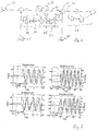
- Fig. 1 shows a simulation, in which at the point of common coupling (PCC) the voltage and the reactive power of a wind energy turbine using standard control settings leads to an amplified oscillation. Reactive power is almost in phase with system voltage, amplifying the voltage oscillations and consequently the electromechanical oscillations.
- PCC point of common coupling
- the voltage controller is primarily designed to fulfil the reactive power dynamics following voltage variations, obtaining damping for electromechanical oscillations is rather exceptionally addressed.
- the results in Fig. 1 emphasize the need to ensure that the wind energy turbine does not amplify occurring power system oscillations.
- the amplifying behavior shown in Fig. 1 is turned into a decrease of the oscillations by a proper phase shift of the reactive power to the voltage.
- the original phase shift is the result of various delays and dynamics in the overall reactive power control loop.
- These controller settings however lead to an undesirable reactive power response to voltage oscillations between 0.6 Hz and 1.0 Hz.
- For a proper damping it is necessary to combine the damping of electromechanical oscillations with the required reactive power dynamics.
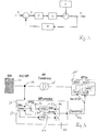
- FIG. 2 shows the control loop with X as the voltage setpoint, C the wind energy turbine, G the system, and H the measurement.
- X the voltage setpoint
- C the wind energy turbine
- G the system
- H the measurement.
- Y CG 1 + CGH X + 1 1 + CGH D .
- the second part of the equation determines to which extent the disturbances D are suppressed or amplified by the wind energy turbine. For the attenuation of electromechanical oscillations it is therefore necessary that the amplitude of 1/(1+CGH) has a negative amplitude in the frequency range of interest and simultaneously ensures a desired step response with a sufficient phase margin to avoid controller instability.
- An additional aspect for the electromechanical power oscillations is to ensure the above mentioned dynamic requirements at varying short-circuit power values at the point of coupling.
- the short-circuit power does not directly influence the set phase shift, though the controller dynamics slightly change.
- a lower short-circuit power causes higher voltage deviations in the system for the same reactive power injection, the phase margin of the controller is typically reduced, making the controller more sensitive.
- Fig. 3 shows schematically an approach for damping of electromechanical oscillations using a wind farm controller.
- Fig. 3 shows a wind farm 10 with a plurality of wind energy turbines WTG1 - WTG5.
- the wind farm 10 is controlled by a wind farm controller 12.
- the wind farm controller 12 provides a sum of reactive power setpoints (Q set,WTGs ) 42 for the wind energy turbines in the wind farm 10.
- the sum of reactive power setpoints 42 is split up into individual reactive power setpoints, for each wind energy turbine in the wind farm 10.
- the wind farm controller 12 is connected to the point of common coupling 14 of the wind farm 10.
- the wind farm 10 is connected to the power system 16 via a wind farm transformer 18.
- the reactive power controller 24 receives a constant voltage setpoint U set 26 and a measured voltage value U meas 28. If the measured voltage value U meas 28 deviates from the constant voltage setpoint U set 26 the reactive power controller 24 supplies a reference reactive power value Q ref 30. The main function of the reference reactive power value Q ref 30 is to stabilize the power system voltage.
- the POD2-device 22 is a switchable device and operates using the reference reactive power value Q ref 30 as input.
- the POD2-device 22 outputs a reactive power setpoint Q set 32.
- a measured reactive power Q meas 29 is subtracted from the reactive power set point 32 in order to provide the sum of reactive power setpoints Q set, WTGs 42for the wind energy turbines of the wind farm.
- the POD1-device 21 operates based on the measured system voltage U meas 28.
- the output of the POD1-device 21 is the sum of setpoint reactive power setpoints (Q set, WTGs ) 42 for the wind energy turbines WTG1-5 of the wind farm 10.
- Fig. 6 shows a constant voltage setpoint U set 26 and the measured system voltage U meas 28.
- the POD1-device 21 receives the measured system voltage U meas 28 as input.
- the POD1-device 21 consists of a filter 34, a gain 36 and a lead-lag compensation 38.
- the filter 34 is adapted as a high-pass filter to eliminate a steady state offset of the POD control loop on the overall response. Moreover, low frequency signals are blocked by the filter. Only signals above a defined frequency are passed to be damped. Alternatively, a band pass filter can be used to also eliminate influences of the damping on the higher frequency content in the oscillatory input.
- the gain 36 determines the amount of damping introduced.
- the gain must be high enough to provide a sufficient damping (if for instance the Q(U)-path does not provide the desired phase shift, the POD-path should be dominant) and sufficiently low to avoid unstable behavior of the overall controller. Thereto, the balance of gains between the control path without POD and the POD-path needs to be well tuned.
- the lead-lag compensation 38 serves as a compensation of the delay caused by the cycle times and dynamics in the overall control loop. This compensation element must ensure that reactive power is injected with a desired phase angle with respect to the oscillatory input.
- An output reactive power Q POD 40 of the POD 1-device 21, the measured reactive power Q meas 29 together with the reference reactive power Q ref 30 as output by the reactive power controller 24 are used to determine a control reactive power setpoint 42.
- Preferable a summation element 41 sums up the values determined as the control reactive power setpoint 42.
- the control reactive power setpoint 42 is applied to a PI-controller 44 and split up into one or more setpoints for different wind energy turbines.
- Fig. 4 shows in a schematical view the measurement device 46 which provides a measured voltage value U meas 28 and a measured reactive power value Q meas 29 by measuring the a voltage U and a current I close the point of common coupling 14.
- the dynamical behavior of the measuring device 46 can be described by using a PT1-element 48 and a dead time element 50.
- the PT1-element 48 corresponds to a 1 st -order lag element.
- the measured voltage value U meas 28 together with the voltage setpoint U set 26 are applied to the reactive power controller 24.
- the reactive power controller 24 outputs a reference reactive power Q ref 30 which is applied to a PI-controller 60 together with the measured reactive power value Q meas 29 bypassing the reactive power controller 24 and the switch unit 58.
- the switch unit can be a hardware switch or a software switch.
- a switch unit 58 provides the reference reactive power Q ref 30 to the PI-controller 60. If a frequency value and an amplitude value of the measured voltage U meas 28 indicate electromechanical oscillations on the power system, the switch unit 58 disconnects the reference reactive power Q ref 30 from the PI-controller 60 and connects the POD2-device 22 with its output value to the PI-controller 60. The switching is triggered if a detection element 76 (cp. Fig. 5 ) detects electromechanical oscillations on the power system.
- Fig. 5 explains the function of the POD2-device 22 in detail.
- the POD2-device 22 can be configured to use either the measured voltage U meas 28 at an input 64 or the reference reactive power Q ref 30 at an alternative input 66.
- the reference reactive power Q ref 30 is applied to a band pass filter 68.
- the band pass filter 68 may also be considered as a band-stop filter which blocks frequencies within its band(s).
- the difference of the output of the band pass filter 68 and the reference reactive power Q ref 30 constitutes an AC signal 72. Together with the original reference reactive power Q ref .
- the difference as provided by a subtractor 70 is applied to 2 nd order lag-element (PT2-element) 74.
- PT2-element 2 nd order lag-element
- the detection of electromechanical oscillations is carried out by the detection element 76.
- Based on an AC signal 78 which is the output of a subtractor 71 subtracting the measured system voltage U meas 28 and a band pass filtered signal 84.
- the detection element 76 determines whether the AC signal 78 of the measured voltage U meas 28 falls within a frequency interval of electromechanical oscillations. The frequency interval is usually between 0.2 Hz and 1.5 Hz.
- the detection element 76 also determines whether the amplitude of the AC signal 78 exceeds a predefined threshold value.
- the frequency value of the AC signal 78 is output as oscillation frequency f osc 80 and applied to the 2 nd order-lag element 74 (PT2-element).
- a POD-bit is set and processed in the switch 82. If the POD bit is set the switch 82 switches to its on state (1) and forwards reactive power Q set,POD 32 based on the output 83 of a summation element 85.
- the PT2-element 74 uses a PT2-gain and a PT2-phase and the detected frequency f osc 80 in order to provide a phasing to the AC signal 72 of the reference reactive power Q ref 30 for damping.
- the output 75 of the 2 nd order-lag element 74 is added to the DC signal 77 as provided by the band pass filter 68 using a summation element 85.
- the switch unit 62 If the switch unit 62 is switched to 0, the AC signal 72 applied to the PT2-element 74 is based on the reference reactive power Q ref 30. However, the AC signal 78 is still used to detect electromechanical oscillations.
- the reference reactive power Q ref 30 as applied to the input 66 is forwarded to a band pass filter 68 which works as band-stop filter to provide a DC-signal 77.
- a subtractor 70 subtracts the DC signal 77 from the original signal of the reference reactive power Q ref 30 to provide the AC signal 72, which is applied to the 2 nd order lag element 74.
- Fig. 7 shows simulation results and measurement results for the voltage and the reactive power for a POD1-device 21 and a POD2-device 22.
- the POD2-device 22 it is within the reactive power signal Q visible that the POD2-device 22 is triggered at the time of about 7.5 seconds.
- the POD2-device 22 is triggered at about 148 seconds.
- POD1-device and the POD2-device can be summarized as follows: In the continuous approach of the POD1-device the continuous activation ensures an adequate phase shift between voltage and reactive power at the point of coupling, also during power system oscillations with low amplitude. A clean control approach with immediate damping as soon as first oscillation swings occur is used. No oscillation detection is needed. This contributes to a high reliability and a low susceptibility to failure.
- the switchable approach of the POD2-device can be summarized as avoiding interference with controller dynamics during normal operation. The POD2-device is only actuated when power system oscillations are detected. The POD2-device settings can be set without influencing the step response dynamics of the system. System interactions are avoided during normal operation. Oscillation detecting makes the POD2-event possible.
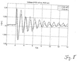
- Fig. 8 shows the voltage behavior with a power oscillation damping on versus power oscillations damping off. As can be seen clearly from Fig. 8 , the voltage oscillation with POD1 are stronger damped than without the POD.
Landscapes
- Engineering & Computer Science (AREA)
- Power Engineering (AREA)
- Life Sciences & Earth Sciences (AREA)
- Sustainable Development (AREA)
- Sustainable Energy (AREA)
- Chemical & Material Sciences (AREA)
- Combustion & Propulsion (AREA)
- Mechanical Engineering (AREA)
- General Engineering & Computer Science (AREA)
- Control Of Eletrric Generators (AREA)
Claims (10)
- Verfahren zur Dämpfung elektromechanischer Schwingungen auf einem Stromversorgungssystem (16) durch Einspeisung von Blindleistung, die von einer oder mehreren Windenergieanlagen (WTG 1-5) erzeugt wird, wobei eine Blindleistungssteuerung (24) angepasst ist, um einen Referenzblindleistungswert (Qref) (30) in Abhängigkeit von einer tatsächlichen Systemspannung (Umeas) (28) zu bestimmen, wobei das Verfahren Folgendes umfasst:- Messen (46) von Schwingungsdaten (28), die dem Stromversorgungssystem (16) zugeordnet sind,- Filtern (84, 71) der gemessenen Schwingungsdaten (28), um einen stationären Offset zu entfernen, wodurch gefilterte Schwingungsdaten erhalten werden,- Bestimmen (76) eines Frequenzwertes (80) und eines Amplitudenwertes aus den gefilterten Schwingungsdaten (78), und- Auslösen (82) einer schaltbaren Leistungsschwingungsdämpfung (74) nach mindestens einem der folgenden Kriterien:∘ der Frequenzwert (80), der aus den gefilterten Schwingungsdaten (78) bestimmt wird, fällt in ein vorgegebenes Frequenzintervall, und∘ der Amplitudenwert, der aus den gefilterten Schwingungsdaten (78) bestimmt wird, überschreitet einen vorbestimmten Schwellenwert,- wobei die schaltbare Leistungsschwingungsdämpfung (74) durch Kompensieren einer Verstärkung und einer Verzögerung, die durch die Blindleistungssteuerung (24) verursacht wird, auf den Referenzblindleistungswert (Qref) erreicht wird, wodurch ein korrigierter Referenzblindleistungswert erhalten wird- wobei zusätzlich zu der vorstehend schaltbaren (82) Leistungsschwingungsdämpfung eine kontinuierliche Leistungsschwingungsdämpfung (60) vorgesehen ist, die die Schritte des Korrigierens einer Verstärkung und einer Verschiebung entweder des korrigierten Referenzblindleistungswertes, falls die schaltbare Leistungsschwingungsdämpfung ausgelöst wird, oder des Referenzblindleistungswertes (Qref), falls die schaltbare Leistungsschwingungsdämpfung nicht ausgelöst wird, umfasst, wodurch eine Verstärkung und eine Verzögerung kompensiert wird, die durch die Blindleistungssteuerung (24) verursacht wird,- Ausgeben eines Blindleistungssollwerts (Qset, WTGs) an mindestens eine der Vielzahl von Windenergieanlagen (WTG 1-5) basierend auf mindestens einem der folgenden Werte: dem Referenzblindleistungswert (Qref) und dem korrigierten Referenzblindleistungswert.
- Verfahren nach Anspruch 1, wobei die gemessenen Schwingungsdaten der tatsächlichen Systemspannung (Umeas) entsprechen.
- Verfahren nach Anspruch 1, wobei die gemessenen Schwingungsdaten der Referenzblindleistung (Qref) entsprechen, die in Abhängigkeit von der tatsächlichen Systemspannung (Umeas) bestimmt wird.
- Verfahren nach einem der Ansprüche 1 bis 3, wobei der Schritt der Filterung der gemessenen Schwingungsdaten eine Bandpassfilterung beinhaltet, um einen Einfluss von Frequenzen zu eliminieren, die höher und niedriger als Frequenzen der elektromechanischen Schwingungen auf die Dämpfung sind.
- Verfahren nach einem der vorhergehenden Ansprüche, wobei das vorgegebene Frequenzintervall zwischen 0,2 Hz und 1,5 Hz, vorzugsweise zwischen 0,5 Hz und 1,1 Hz, und besonders bevorzugt zwischen 0,6 Hz und 1 Hz liegt.
- Verfahren gemäß einem der vorhergehenden Ansprüche, wobei die Schwingungsdaten auf ein Verzögerungselement zweiter Ordnung (PT2) angewendet werden.
- Verfahren nach Anspruch 6, wobei das Verzögerungselement zweiter Ordnung (PT2) von mindestens einem der folgenden aus den Schwingungsdaten erhaltenen Daten abhängt: Frequenz, Verstärkung, Phase und Amplitude.
- Windpark (10), der mit einem Stromversorgungssystem (16) verbunden ist, wobei der Windpark (10) eine Vielzahl von Windkraftanlagen (WTG 1-5) umfasst, umfassend eine Windparksteuerung (12), die zum Bereitstellen von Sollwerten für Wirk- und Blindleistung (Qset, WTGs) für jede der Vielzahl von Windkraftanlagen (WTG 1-5) angeordnet ist, und eine Messvorrichtung zum Messen von Schwingungsdaten (28), die dem Stromversorgungssystem (16) zugeordnet sind, wobei die Windparksteuerung umfasst:- eine Filtereinheit (34), die zum Entfernen eines stationären Offsets aus den gemessenen Schwingungsdaten (28) angepasst ist, um dadurch gefilterte Schwingungsdaten zu erhalten,- eine Blindleistungssteuerung (24), die zum Bereitstellen eines Referenzblindleistungswertes (Qref) in Abhängigkeit von einer tatsächlichen Systemspannung (Umeas) angeordnet ist,- eine schaltbare Leistungsschwingungsdämpfungsvorrichtung (POD), die zum Dämpfen elektromechanischer Schwingungen auf dem Stromversorgungssystem (16) und zum Kompensieren mindestens eines der folgenden Effekte, die durch die Blindleistungssteuerung verursacht werden, geeignet ist:o eine Verstärkung, die von der Blindleistungssteuerung (24) auf den Referenzblindleistungswert (Qref) angewendet wird, undo eine Verzögerung, die von der Blindleistungssteuerung (24) auf den Referenzblindleistungswert (Qref) angewandt wird, wodurch ein korrigierter Referenzblindleistungswert erhalten wird,- ein Erfassungselement (76), das zum Bestimmen eines Frequenzwertes (80) und eines Amplitudenwertes aus den gefilterten Schwingungsdaten (28) und zum Auslösen (82) der Dämpfung der schaltbaren Leistungsschwingungsdämpfungsvorrichtung gemäß mindestens einem der folgenden Kriterien geeignet ist:o der Frequenzwert (80), der aus den gefilterten Schwingungsdaten (78) bestimmt wird, fällt in ein vorgegebenes Frequenzintervall, undo der Amplitudenwert, der aus den gefilterten Schwingungsdaten (78) bestimmt wird, überschreitet einen vorbestimmten Schwellenwert- eine Vorrichtung (60) zum Dämpfen von kontinuierlichen Leistungsschwingungen, die zum Ausführen der Schritte des Korrigierens einer Verstärkung und einer Verschiebung entweder des korrigierten Referenzblindleistungswertes, falls die schaltbare Leistungsschwingungsdämpfung ausgelöst wird, oder des Referenzblindleistungswertes (Qref), falls die schaltbare Leistungsschwingungsdämpfung nicht ausgelöst wird, geeignet ist, wodurch eine Verstärkung und eine Verzögerung kompensiert wird, die durch die Blindleistungssteuerung verursacht wird,- wobei die Windparksteuerung (12) angepasst ist, um einen Blindleistungssollwert (Qset, WTGs) an mindestens eine der Vielzahl von Windkraftanlagen (WTG 1-5) auszugeben, basierend auf mindestens einem von: dem Referenzblindleistungswert (Qref) und dem korrigierten Referenzblindleistungswert der schaltbaren Leistungsschwingungsdämpfungsvorrichtung (POD).
- Windpark nach Anspruch 8, wobei die Windparksteuerung eine Schalteinheit umfasst, die zum Bestimmen eines Frequenzwertes und eines Amplitudenwertes aus den gefilterten Schwingungsdaten und zum Schalten der POD-Vorrichtung basierend auf mindestens einem der folgenden Kriterien angeordnet ist:o den Frequenzwert, der aus den gefilterten Schwingungsdaten bestimmt wird, fällt in ein vorgegebenes Frequenzintervall, undo der Amplitudenwert, der aus den gefilterten Schwingungsdaten bestimmt wird, überschreitet einen vorbestimmten Schwellenwert.
- Windpark nach Anspruch 8 oder 9, der zum Dämpfen elektromechanischer Schwingungen am Stromversorgungssystem nach einem der vorhergehenden Verfahren nach Anspruch 1 bis 8 ausgelegt ist.
Priority Applications (4)
| Application Number | Priority Date | Filing Date | Title |
|---|---|---|---|
| DK16198705.2T DK3322060T3 (da) | 2016-11-14 | 2016-11-14 | Fremgangsmåde til dæmpning af elektromekaniske svingninger på et energiforsyningssystem |
| ES16198705T ES2776410T3 (es) | 2016-11-14 | 2016-11-14 | Método de amortiguación de oscilaciones electromecánicas en un sistema de alimentación |
| EP16198705.2A EP3322060B1 (de) | 2016-11-14 | 2016-11-14 | Verfahren zur dämpfung elektromechanischer schwingungen auf einem stromversorgungssystem |
| US15/809,669 US20180138709A1 (en) | 2016-11-14 | 2017-11-10 | Method of damping electromechanical oscillations on a power system |
Applications Claiming Priority (1)
| Application Number | Priority Date | Filing Date | Title |
|---|---|---|---|
| EP16198705.2A EP3322060B1 (de) | 2016-11-14 | 2016-11-14 | Verfahren zur dämpfung elektromechanischer schwingungen auf einem stromversorgungssystem |
Publications (2)
| Publication Number | Publication Date |
|---|---|
| EP3322060A1 EP3322060A1 (de) | 2018-05-16 |
| EP3322060B1 true EP3322060B1 (de) | 2019-12-25 |
Family
ID=57326220
Family Applications (1)
| Application Number | Title | Priority Date | Filing Date |
|---|---|---|---|
| EP16198705.2A Active EP3322060B1 (de) | 2016-11-14 | 2016-11-14 | Verfahren zur dämpfung elektromechanischer schwingungen auf einem stromversorgungssystem |
Country Status (4)
| Country | Link |
|---|---|
| US (1) | US20180138709A1 (de) |
| EP (1) | EP3322060B1 (de) |
| DK (1) | DK3322060T3 (de) |
| ES (1) | ES2776410T3 (de) |
Families Citing this family (24)
| Publication number | Priority date | Publication date | Assignee | Title |
|---|---|---|---|---|
| EP3322061A1 (de) * | 2016-11-14 | 2018-05-16 | Nordex Energy GmbH | Verfahren zur dämpfung elektromechanischer schwingungen auf einem stromversorgungssystem |
| DE102018116445A1 (de) * | 2018-07-06 | 2020-01-09 | Wobben Properties Gmbh | Verfahren zum Erkennen niederfrequenter Schwingungen und Erfassungseinrichtung dafür |
| DE102018116444A1 (de) * | 2018-07-06 | 2020-01-09 | Wobben Properties Gmbh | Verfahren zum Steuern eines Windparks |
| DE102018116443A1 (de) | 2018-07-06 | 2020-01-09 | Wobben Properties Gmbh | Verfahren zum Steuern eines Windparks |
| DE102018116446A1 (de) * | 2018-07-06 | 2020-01-09 | Wobben Properties Gmbh | Windenergiesystem und Verfahren zum Erkennen niederfrequenter Schwingungen in einem elektrischen Versorgungsnetz |
| CN109217335B (zh) * | 2018-08-22 | 2020-07-10 | 华中科技大学 | 一种海上风电vsc-hvdc输出系统的交流电力系统低频振荡阻尼控制方法 |
| DE102018120751A1 (de) | 2018-08-24 | 2020-02-27 | Wobben Properties Gmbh | Windenergieanlage und Verfahren zum Erkennen niederfrequenter Schwingungen in einem elektrischen Versorgungsnetz |
| CN109738058A (zh) * | 2019-02-15 | 2019-05-10 | 江苏弘冉智能科技有限公司 | 一种自学习振动故障诊断方法 |
| CN110137941B (zh) * | 2019-04-10 | 2022-11-11 | 中国电力科学研究院有限公司 | 一种基于双馈风机稳定性影响的电网稳定控制方法及装置 |
| CN111106611B (zh) * | 2019-11-19 | 2022-09-02 | 中国电力科学研究院有限公司 | 基于增益守恒的静态无功补偿器协调阻尼设计方法及装置 |
| CN111262258B (zh) * | 2020-03-19 | 2024-05-24 | 国网天津市电力公司电力科学研究院 | 用于多端柔性直流系统的附加阻尼内环控制方法及控制器 |
| CN111577552B (zh) * | 2020-03-31 | 2021-06-25 | 华电电力科学研究院有限公司 | 一种高低速插值拟合的风电机组振动信号归一化方法 |
| CN112003266B (zh) * | 2020-07-09 | 2022-10-18 | 云南电网有限责任公司 | 评估不同位置并联型无功补偿装置对频率振荡影响的方法 |
| CN111817317B (zh) * | 2020-07-30 | 2022-04-29 | 四川大学 | 具有串补线路的风力发电系统次同步振荡定量分析方法 |
| US11637428B2 (en) * | 2020-09-29 | 2023-04-25 | Mitsubishi Electric Power Products, Inc. | Selective power oscillation damping control system with damping ratio dynamic gain and method for the same |
| CN113612262B (zh) * | 2021-07-15 | 2024-05-31 | 国网江苏省电力有限公司电力科学研究院 | 一种抑制直流侧低频振荡的方法及系统 |
| CN113890115B (zh) * | 2021-09-28 | 2024-06-11 | 杭州意能电力技术有限公司 | 用于抑制电网功率振荡的新能源电站控制系统 |
| EP4170848A1 (de) * | 2021-10-20 | 2023-04-26 | Wobben Properties GmbH | Verfahren zum dämpfen niederfrequenter schwingungen in einem elektrischen versorgungsnetz |
| CN114006386B (zh) * | 2021-11-10 | 2023-08-22 | 南方电网科学研究院有限责任公司 | 一种抑制全功率变流器并网宽频振荡的控制方法和系统 |
| EP4459823A1 (de) * | 2023-05-05 | 2024-11-06 | Hitachi Energy Ltd | Adaptiver leistungsschwingungsdämpfungsregler für einen netzformungswandler |
| CN116995689B (zh) * | 2023-07-04 | 2024-03-08 | 华北电力大学(保定) | 一种双馈风电场抑制次同步振荡的混合阻尼控制方法 |
| CN117335452B (zh) * | 2023-07-25 | 2025-05-30 | 长江勘测规划设计研究有限责任公司 | 一种混合储能系统阻尼控制器参数快速整定方法 |
| CN117200350B (zh) * | 2023-09-11 | 2024-03-26 | 国网江苏省电力有限公司电力科学研究院 | 一种多风机并网发电系统的阻尼贡献稳定评估方法及装置 |
| US12261439B1 (en) | 2023-12-11 | 2025-03-25 | Vestas Wind Systems A/S | Method for damping power oscillation in an electric power grid |
Family Cites Families (8)
| Publication number | Priority date | Publication date | Assignee | Title |
|---|---|---|---|---|
| US8058753B2 (en) * | 2008-10-31 | 2011-11-15 | General Electric Company | Wide area transmission control of windfarms |
| US9478987B2 (en) | 2009-11-10 | 2016-10-25 | Siemens Aktiengesellschaft | Power oscillation damping employing a full or partial conversion wind turbine |
| WO2011112571A2 (en) | 2010-03-11 | 2011-09-15 | Siemens Energy, Inc. | Method and system for damping subsynchronous resonant oscillations in a power system using a wind turbine |
| US8618694B2 (en) | 2010-06-30 | 2013-12-31 | Vestas Wind Systems A/S | System, method, and computer program product for utilizing a wind park as a variable power system stabilizer |
| CA2812627C (en) | 2010-09-28 | 2019-10-29 | Siemens Aktiengesellschaft | Power oscillation damping by a converter-based power generation device |
| CN103858301B (zh) | 2011-09-30 | 2016-09-07 | 维斯塔斯风力系统集团公司 | 用于抑制电网振荡的控制设备 |
| CA2911901A1 (en) | 2014-11-14 | 2016-05-14 | Gl Pwrsolutions, Inc. | Power system sub-synchronous oscillation damper |
| EP3322061A1 (de) * | 2016-11-14 | 2018-05-16 | Nordex Energy GmbH | Verfahren zur dämpfung elektromechanischer schwingungen auf einem stromversorgungssystem |
-
2016
- 2016-11-14 DK DK16198705.2T patent/DK3322060T3/da active
- 2016-11-14 ES ES16198705T patent/ES2776410T3/es active Active
- 2016-11-14 EP EP16198705.2A patent/EP3322060B1/de active Active
-
2017
- 2017-11-10 US US15/809,669 patent/US20180138709A1/en not_active Abandoned
Non-Patent Citations (1)
| Title |
|---|
| None * |
Also Published As
| Publication number | Publication date |
|---|---|
| ES2776410T3 (es) | 2020-07-30 |
| EP3322060A1 (de) | 2018-05-16 |
| DK3322060T3 (da) | 2020-03-23 |
| US20180138709A1 (en) | 2018-05-17 |
Similar Documents
| Publication | Publication Date | Title |
|---|---|---|
| EP3322060A1 (de) | Verfahren zur dämpfung elektromechanischer schwingungen auf einem stromversorgungssystem | |
| EP3322061A1 (de) | Verfahren zur dämpfung elektromechanischer schwingungen auf einem stromversorgungssystem | |
| CA2812708C (en) | Power oscillation damping controller | |
| US8710700B2 (en) | Power or voltage oscillation damping in a power transmission system | |
| EP2572426B1 (de) | Anordnung zur erzeugung eines steuersignals zur steuerung einer leistungsabgabe eines stromerzeugungssystem | |
| US7271571B2 (en) | Anti-islanding protection systems for synchronous machine based distributed generators | |
| EP3075054B1 (de) | Rekonfiguration der blindleistungsschleife einer windenergieanlage | |
| US11258256B2 (en) | Wind power plant with improved rise time | |
| EP3077662B1 (de) | Grundrasterüberwachung einer windenergieanlage | |
| CN102084572A (zh) | 发电机网络和本地电力系统 | |
| JP2015523048A (ja) | ウインドパークを制御する方法 | |
| US11411519B2 (en) | Method for handling sub-synchronous resonances | |
| WO2013142553A2 (en) | System and method for islanding detection and protection | |
| Surjan et al. | Power system stabilizer controller design for SMIB stability study | |
| CN109154275A (zh) | 在异常电网事件期间运行风力涡轮机发电机 | |
| Soens et al. | Equivalent transfer function for a variable speed wind turbine in power system dynamic simulations | |
| JP3302875B2 (ja) | 系統連系保護用無効電力補償装置 | |
| Fernandez et al. | Contribution of wind farms to the network stability | |
| US11411403B2 (en) | Controlling power distribution at deadband states | |
| CN108539762A (zh) | 一种基于自抗扰的风力发电机系统的频率控制系统及方法 | |
| Li | Improvement to observability measures of LFO modes in power systems with DFIGs | |
| US10727843B2 (en) | Method for operating a wind turbine | |
| Winter et al. | Islanding Dependencies and Detection in low-Voltage grids with grid forming Inverters | |
| Gupta et al. | Single area load frequency control using traditional conventional tuning method | |
| CN121055505A (zh) | 一种用于抑制不对称故障下负序电流的自适应参数调整方法及系统 |
Legal Events
| Date | Code | Title | Description |
|---|---|---|---|
| PUAI | Public reference made under article 153(3) epc to a published international application that has entered the european phase |
Free format text: ORIGINAL CODE: 0009012 |
|
| STAA | Information on the status of an ep patent application or granted ep patent |
Free format text: STATUS: THE APPLICATION HAS BEEN PUBLISHED |
|
| AK | Designated contracting states |
Kind code of ref document: A1 Designated state(s): AL AT BE BG CH CY CZ DE DK EE ES FI FR GB GR HR HU IE IS IT LI LT LU LV MC MK MT NL NO PL PT RO RS SE SI SK SM TR |
|
| AX | Request for extension of the european patent |
Extension state: BA ME |
|
| STAA | Information on the status of an ep patent application or granted ep patent |
Free format text: STATUS: REQUEST FOR EXAMINATION WAS MADE |
|
| 17P | Request for examination filed |
Effective date: 20181114 |
|
| RBV | Designated contracting states (corrected) |
Designated state(s): AL AT BE BG CH CY CZ DE DK EE ES FI FR GB GR HR HU IE IS IT LI LT LU LV MC MK MT NL NO PL PT RO RS SE SI SK SM TR |
|
| STAA | Information on the status of an ep patent application or granted ep patent |
Free format text: STATUS: EXAMINATION IS IN PROGRESS |
|
| 17Q | First examination report despatched |
Effective date: 20190208 |
|
| GRAP | Despatch of communication of intention to grant a patent |
Free format text: ORIGINAL CODE: EPIDOSNIGR1 |
|
| STAA | Information on the status of an ep patent application or granted ep patent |
Free format text: STATUS: GRANT OF PATENT IS INTENDED |
|
| INTG | Intention to grant announced |
Effective date: 20190918 |
|
| GRAS | Grant fee paid |
Free format text: ORIGINAL CODE: EPIDOSNIGR3 |
|
| RIN1 | Information on inventor provided before grant (corrected) |
Inventor name: BODE, FLORIAN Inventor name: HAMANN, NIELS Inventor name: DE RIJCKE, SIMON |
|
| GRAA | (expected) grant |
Free format text: ORIGINAL CODE: 0009210 |
|
| STAA | Information on the status of an ep patent application or granted ep patent |
Free format text: STATUS: THE PATENT HAS BEEN GRANTED |
|
| AK | Designated contracting states |
Kind code of ref document: B1 Designated state(s): AL AT BE BG CH CY CZ DE DK EE ES FI FR GB GR HR HU IE IS IT LI LT LU LV MC MK MT NL NO PL PT RO RS SE SI SK SM TR |
|
| REG | Reference to a national code |
Ref country code: GB Ref legal event code: FG4D |
|
| RIN1 | Information on inventor provided before grant (corrected) |
Inventor name: BODE, FLORIAN Inventor name: HAMANN, NIELS Inventor name: DE RIJCKE, SIMON |
|
| REG | Reference to a national code |
Ref country code: CH Ref legal event code: EP |
|
| REG | Reference to a national code |
Ref country code: DE Ref legal event code: R096 Ref document number: 602016026757 Country of ref document: DE |
|
| REG | Reference to a national code |
Ref country code: AT Ref legal event code: REF Ref document number: 1218189 Country of ref document: AT Kind code of ref document: T Effective date: 20200115 |
|
| RIN2 | Information on inventor provided after grant (corrected) |
Inventor name: DE RIJCKE, SIMON Inventor name: HAMANN, NIELS Inventor name: BODE, FLORIAN |
|
| REG | Reference to a national code |
Ref country code: IE Ref legal event code: FG4D |
|
| REG | Reference to a national code |
Ref country code: DK Ref legal event code: T3 Effective date: 20200318 |
|
| REG | Reference to a national code |
Ref country code: NL Ref legal event code: MP Effective date: 20191225 |
|
| PG25 | Lapsed in a contracting state [announced via postgrant information from national office to epo] |
Ref country code: LV Free format text: LAPSE BECAUSE OF FAILURE TO SUBMIT A TRANSLATION OF THE DESCRIPTION OR TO PAY THE FEE WITHIN THE PRESCRIBED TIME-LIMIT Effective date: 20191225 Ref country code: SE Free format text: LAPSE BECAUSE OF FAILURE TO SUBMIT A TRANSLATION OF THE DESCRIPTION OR TO PAY THE FEE WITHIN THE PRESCRIBED TIME-LIMIT Effective date: 20191225 Ref country code: FI Free format text: LAPSE BECAUSE OF FAILURE TO SUBMIT A TRANSLATION OF THE DESCRIPTION OR TO PAY THE FEE WITHIN THE PRESCRIBED TIME-LIMIT Effective date: 20191225 Ref country code: BG Free format text: LAPSE BECAUSE OF FAILURE TO SUBMIT A TRANSLATION OF THE DESCRIPTION OR TO PAY THE FEE WITHIN THE PRESCRIBED TIME-LIMIT Effective date: 20200325 Ref country code: NO Free format text: LAPSE BECAUSE OF FAILURE TO SUBMIT A TRANSLATION OF THE DESCRIPTION OR TO PAY THE FEE WITHIN THE PRESCRIBED TIME-LIMIT Effective date: 20200325 Ref country code: GR Free format text: LAPSE BECAUSE OF FAILURE TO SUBMIT A TRANSLATION OF THE DESCRIPTION OR TO PAY THE FEE WITHIN THE PRESCRIBED TIME-LIMIT Effective date: 20200326 Ref country code: LT Free format text: LAPSE BECAUSE OF FAILURE TO SUBMIT A TRANSLATION OF THE DESCRIPTION OR TO PAY THE FEE WITHIN THE PRESCRIBED TIME-LIMIT Effective date: 20191225 |
|
| REG | Reference to a national code |
Ref country code: LT Ref legal event code: MG4D |
|
| PG25 | Lapsed in a contracting state [announced via postgrant information from national office to epo] |
Ref country code: HR Free format text: LAPSE BECAUSE OF FAILURE TO SUBMIT A TRANSLATION OF THE DESCRIPTION OR TO PAY THE FEE WITHIN THE PRESCRIBED TIME-LIMIT Effective date: 20191225 Ref country code: RS Free format text: LAPSE BECAUSE OF FAILURE TO SUBMIT A TRANSLATION OF THE DESCRIPTION OR TO PAY THE FEE WITHIN THE PRESCRIBED TIME-LIMIT Effective date: 20191225 |
|
| PG25 | Lapsed in a contracting state [announced via postgrant information from national office to epo] |
Ref country code: AL Free format text: LAPSE BECAUSE OF FAILURE TO SUBMIT A TRANSLATION OF THE DESCRIPTION OR TO PAY THE FEE WITHIN THE PRESCRIBED TIME-LIMIT Effective date: 20191225 |
|
| REG | Reference to a national code |
Ref country code: ES Ref legal event code: FG2A Ref document number: 2776410 Country of ref document: ES Kind code of ref document: T3 Effective date: 20200730 |
|
| PG25 | Lapsed in a contracting state [announced via postgrant information from national office to epo] |
Ref country code: EE Free format text: LAPSE BECAUSE OF FAILURE TO SUBMIT A TRANSLATION OF THE DESCRIPTION OR TO PAY THE FEE WITHIN THE PRESCRIBED TIME-LIMIT Effective date: 20191225 Ref country code: NL Free format text: LAPSE BECAUSE OF FAILURE TO SUBMIT A TRANSLATION OF THE DESCRIPTION OR TO PAY THE FEE WITHIN THE PRESCRIBED TIME-LIMIT Effective date: 20191225 Ref country code: PT Free format text: LAPSE BECAUSE OF FAILURE TO SUBMIT A TRANSLATION OF THE DESCRIPTION OR TO PAY THE FEE WITHIN THE PRESCRIBED TIME-LIMIT Effective date: 20200520 Ref country code: RO Free format text: LAPSE BECAUSE OF FAILURE TO SUBMIT A TRANSLATION OF THE DESCRIPTION OR TO PAY THE FEE WITHIN THE PRESCRIBED TIME-LIMIT Effective date: 20191225 |
|
| PG25 | Lapsed in a contracting state [announced via postgrant information from national office to epo] |
Ref country code: SM Free format text: LAPSE BECAUSE OF FAILURE TO SUBMIT A TRANSLATION OF THE DESCRIPTION OR TO PAY THE FEE WITHIN THE PRESCRIBED TIME-LIMIT Effective date: 20191225 Ref country code: IS Free format text: LAPSE BECAUSE OF FAILURE TO SUBMIT A TRANSLATION OF THE DESCRIPTION OR TO PAY THE FEE WITHIN THE PRESCRIBED TIME-LIMIT Effective date: 20200425 Ref country code: SK Free format text: LAPSE BECAUSE OF FAILURE TO SUBMIT A TRANSLATION OF THE DESCRIPTION OR TO PAY THE FEE WITHIN THE PRESCRIBED TIME-LIMIT Effective date: 20191225 |
|
| REG | Reference to a national code |
Ref country code: DE Ref legal event code: R097 Ref document number: 602016026757 Country of ref document: DE |
|
| PG25 | Lapsed in a contracting state [announced via postgrant information from national office to epo] |
Ref country code: CZ Free format text: LAPSE BECAUSE OF FAILURE TO SUBMIT A TRANSLATION OF THE DESCRIPTION OR TO PAY THE FEE WITHIN THE PRESCRIBED TIME-LIMIT Effective date: 20191225 |
|
| PLBE | No opposition filed within time limit |
Free format text: ORIGINAL CODE: 0009261 |
|
| STAA | Information on the status of an ep patent application or granted ep patent |
Free format text: STATUS: NO OPPOSITION FILED WITHIN TIME LIMIT |
|
| REG | Reference to a national code |
Ref country code: AT Ref legal event code: MK05 Ref document number: 1218189 Country of ref document: AT Kind code of ref document: T Effective date: 20191225 |
|
| PG25 | Lapsed in a contracting state [announced via postgrant information from national office to epo] |
Ref country code: SI Free format text: LAPSE BECAUSE OF FAILURE TO SUBMIT A TRANSLATION OF THE DESCRIPTION OR TO PAY THE FEE WITHIN THE PRESCRIBED TIME-LIMIT Effective date: 20191225 |
|
| 26N | No opposition filed |
Effective date: 20200928 |
|
| PG25 | Lapsed in a contracting state [announced via postgrant information from national office to epo] |
Ref country code: IT Free format text: LAPSE BECAUSE OF FAILURE TO SUBMIT A TRANSLATION OF THE DESCRIPTION OR TO PAY THE FEE WITHIN THE PRESCRIBED TIME-LIMIT Effective date: 20191225 Ref country code: AT Free format text: LAPSE BECAUSE OF FAILURE TO SUBMIT A TRANSLATION OF THE DESCRIPTION OR TO PAY THE FEE WITHIN THE PRESCRIBED TIME-LIMIT Effective date: 20191225 |
|
| REG | Reference to a national code |
Ref country code: DE Ref legal event code: R082 Ref document number: 602016026757 Country of ref document: DE Representative=s name: HAUCK PATENT- UND RECHTSANWAELTE PARTMBB, DE Ref country code: DE Ref legal event code: R082 Ref document number: 602016026757 Country of ref document: DE Representative=s name: HAUCK PATENTANWALTSPARTNERSCHAFT MBB, DE Ref country code: DE Ref legal event code: R081 Ref document number: 602016026757 Country of ref document: DE Owner name: NORDEX ENERGY SE & CO. KG, DE Free format text: FORMER OWNER: NORDEX ENERGY GMBH, 22419 HAMBURG, DE |
|
| PG25 | Lapsed in a contracting state [announced via postgrant information from national office to epo] |
Ref country code: PL Free format text: LAPSE BECAUSE OF FAILURE TO SUBMIT A TRANSLATION OF THE DESCRIPTION OR TO PAY THE FEE WITHIN THE PRESCRIBED TIME-LIMIT Effective date: 20191225 |
|
| PG25 | Lapsed in a contracting state [announced via postgrant information from national office to epo] |
Ref country code: MC Free format text: LAPSE BECAUSE OF FAILURE TO SUBMIT A TRANSLATION OF THE DESCRIPTION OR TO PAY THE FEE WITHIN THE PRESCRIBED TIME-LIMIT Effective date: 20191225 |
|
| REG | Reference to a national code |
Ref country code: CH Ref legal event code: PL |
|
| GBPC | Gb: european patent ceased through non-payment of renewal fee |
Effective date: 20201114 |
|
| PG25 | Lapsed in a contracting state [announced via postgrant information from national office to epo] |
Ref country code: LU Free format text: LAPSE BECAUSE OF NON-PAYMENT OF DUE FEES Effective date: 20201114 |
|
| REG | Reference to a national code |
Ref country code: BE Ref legal event code: MM Effective date: 20201130 |
|
| PG25 | Lapsed in a contracting state [announced via postgrant information from national office to epo] |
Ref country code: CH Free format text: LAPSE BECAUSE OF NON-PAYMENT OF DUE FEES Effective date: 20201130 Ref country code: LI Free format text: LAPSE BECAUSE OF NON-PAYMENT OF DUE FEES Effective date: 20201130 |
|
| PG25 | Lapsed in a contracting state [announced via postgrant information from national office to epo] |
Ref country code: IE Free format text: LAPSE BECAUSE OF NON-PAYMENT OF DUE FEES Effective date: 20201114 Ref country code: FR Free format text: LAPSE BECAUSE OF NON-PAYMENT OF DUE FEES Effective date: 20201130 |
|
| PG25 | Lapsed in a contracting state [announced via postgrant information from national office to epo] |
Ref country code: GB Free format text: LAPSE BECAUSE OF NON-PAYMENT OF DUE FEES Effective date: 20201114 |
|
| PG25 | Lapsed in a contracting state [announced via postgrant information from national office to epo] |
Ref country code: TR Free format text: LAPSE BECAUSE OF FAILURE TO SUBMIT A TRANSLATION OF THE DESCRIPTION OR TO PAY THE FEE WITHIN THE PRESCRIBED TIME-LIMIT Effective date: 20191225 Ref country code: MT Free format text: LAPSE BECAUSE OF FAILURE TO SUBMIT A TRANSLATION OF THE DESCRIPTION OR TO PAY THE FEE WITHIN THE PRESCRIBED TIME-LIMIT Effective date: 20191225 Ref country code: CY Free format text: LAPSE BECAUSE OF FAILURE TO SUBMIT A TRANSLATION OF THE DESCRIPTION OR TO PAY THE FEE WITHIN THE PRESCRIBED TIME-LIMIT Effective date: 20191225 |
|
| PG25 | Lapsed in a contracting state [announced via postgrant information from national office to epo] |
Ref country code: MK Free format text: LAPSE BECAUSE OF FAILURE TO SUBMIT A TRANSLATION OF THE DESCRIPTION OR TO PAY THE FEE WITHIN THE PRESCRIBED TIME-LIMIT Effective date: 20191225 |
|
| PG25 | Lapsed in a contracting state [announced via postgrant information from national office to epo] |
Ref country code: BE Free format text: LAPSE BECAUSE OF NON-PAYMENT OF DUE FEES Effective date: 20201130 |
|
| P01 | Opt-out of the competence of the unified patent court (upc) registered |
Effective date: 20230602 |
|
| REG | Reference to a national code |
Ref country code: DE Ref legal event code: R079 Ref document number: 602016026757 Country of ref document: DE Free format text: PREVIOUS MAIN CLASS: H02J0003240000 Ipc: H02J0003001400 |
|
| PGFP | Annual fee paid to national office [announced via postgrant information from national office to epo] |
Ref country code: DE Payment date: 20251118 Year of fee payment: 10 |
|
| PGFP | Annual fee paid to national office [announced via postgrant information from national office to epo] |
Ref country code: DK Payment date: 20251119 Year of fee payment: 10 |
|
| PGFP | Annual fee paid to national office [announced via postgrant information from national office to epo] |
Ref country code: ES Payment date: 20251216 Year of fee payment: 10 |