EP3322087B1 - Motorsteuerungsvorrichtung, verdichter und klimaanlage - Google Patents
Motorsteuerungsvorrichtung, verdichter und klimaanlage Download PDFInfo
- Publication number
- EP3322087B1 EP3322087B1 EP15898223.1A EP15898223A EP3322087B1 EP 3322087 B1 EP3322087 B1 EP 3322087B1 EP 15898223 A EP15898223 A EP 15898223A EP 3322087 B1 EP3322087 B1 EP 3322087B1
- Authority
- EP
- European Patent Office
- Prior art keywords
- motor
- current
- unit
- load
- value
- Prior art date
- Legal status (The legal status is an assumption and is not a legal conclusion. Google has not performed a legal analysis and makes no representation as to the accuracy of the status listed.)
- Active
Links
Images


Classifications
-
- H—ELECTRICITY
- H02—GENERATION; CONVERSION OR DISTRIBUTION OF ELECTRIC POWER
- H02P—CONTROL OR REGULATION OF ELECTRIC MOTORS, ELECTRIC GENERATORS OR DYNAMO-ELECTRIC CONVERTERS; CONTROLLING TRANSFORMERS, REACTORS OR CHOKE COILS
- H02P6/00—Arrangements for controlling synchronous motors or other dynamo-electric motors using electronic commutation dependent on the rotor position; Electronic commutators therefor
- H02P6/14—Electronic commutators
- H02P6/15—Controlling commutation time
-
- H—ELECTRICITY
- H02—GENERATION; CONVERSION OR DISTRIBUTION OF ELECTRIC POWER
- H02P—CONTROL OR REGULATION OF ELECTRIC MOTORS, ELECTRIC GENERATORS OR DYNAMO-ELECTRIC CONVERTERS; CONTROLLING TRANSFORMERS, REACTORS OR CHOKE COILS
- H02P6/00—Arrangements for controlling synchronous motors or other dynamo-electric motors using electronic commutation dependent on the rotor position; Electronic commutators therefor
- H02P6/28—Arrangements for controlling current
-
- H—ELECTRICITY
- H02—GENERATION; CONVERSION OR DISTRIBUTION OF ELECTRIC POWER
- H02P—CONTROL OR REGULATION OF ELECTRIC MOTORS, ELECTRIC GENERATORS OR DYNAMO-ELECTRIC CONVERTERS; CONTROLLING TRANSFORMERS, REACTORS OR CHOKE COILS
- H02P23/00—Arrangements or methods for the control of AC motors characterised by a control method other than vector control
- H02P23/26—Power factor control [PFC]
-
- H—ELECTRICITY
- H02—GENERATION; CONVERSION OR DISTRIBUTION OF ELECTRIC POWER
- H02P—CONTROL OR REGULATION OF ELECTRIC MOTORS, ELECTRIC GENERATORS OR DYNAMO-ELECTRIC CONVERTERS; CONTROLLING TRANSFORMERS, REACTORS OR CHOKE COILS
- H02P29/00—Arrangements for regulating or controlling electric motors, appropriate for both AC and DC motors
-
- H—ELECTRICITY
- H02—GENERATION; CONVERSION OR DISTRIBUTION OF ELECTRIC POWER
- H02P—CONTROL OR REGULATION OF ELECTRIC MOTORS, ELECTRIC GENERATORS OR DYNAMO-ELECTRIC CONVERTERS; CONTROLLING TRANSFORMERS, REACTORS OR CHOKE COILS
- H02P29/00—Arrangements for regulating or controlling electric motors, appropriate for both AC and DC motors
- H02P29/02—Providing protection against overload without automatic interruption of supply
- H02P29/024—Detecting a fault condition, e.g. short circuit, locked rotor, open circuit or loss of load
- H02P29/0241—Detecting a fault condition, e.g. short circuit, locked rotor, open circuit or loss of load the fault being an overvoltage
Definitions
- the present invention relates to a motor control device, a compressor, and an air-conditioning apparatus that incorporate a function of controlling driving of various motors.
- a conventional air-conditioning apparatus equipped with an inverter circuit that switches on and off at certain intervals a direct-current voltage output from a rectifying circuit and converts the direct-current voltage into an alternating-current voltage to variably control a speed of a motor in a compressor installed into an air-conditioning apparatus or other apparatuses.
- a motor having a rare earth permanent magnet disposed inside a rotor hereinafter referred to as a permanent magnet synchronous motor is commonly used as a motor in a compressor.
- a magnetic-pole position of a permanent magnet in a rotor is detected with a position sensor, for example, and a rotation speed of a permanent magnet synchronous motor is controlled on the basis of the magnetic-pole phase at which a current is detected. It has also been proposed that, for example, a rotation speed of a permanent magnet synchronous motor is controlled without using a magnetic-flux sensor (hereinafter referred to as position-sensorless control), (refer to Patent Literature 1, for example).
- position-sensorless control disclosed in Patent Literature 1 is used, for example, in a situation in which the interior of a compressor in an air-conditioning apparatus is under a high-temperature and high-pressure condition that is unsuitable for installing a magnetic-flux sensor into the compressor.
- Patent Literature 2 discloses a motor protection system in conjunction with a controller monitoring the performance of redundant motor-driven prime movers having a lead prime mover and a lag prime mover.
- the controller uses motor protection measurements to determine if the lead motor-driven prime mover is in distress and activates operation of the lag motor-driven prime mover when lead prime mover is in distress.
- Patent Literature 3 a method for checking out-of-step of a synchronous motor is described in which electric degrees of the synchronous motor re detected and compared to each other to obtain a comparing result. It is determined that the synchronous motor is out of step when the comparing result satisfies a preset requirement.
- a motor that is controlled by the position-sensorless control disclosed in Patent Literature 1 is also likely to go out of synchronization because a magnetic-pole position of a rotor is not directly detected.
- Liquefied refrigerant is usually stored in an accumulator, and a compressor does not suction the liquefied refrigerant.
- the compressor may suction the liquefied refrigerant.
- the load torque may change rapidly, and the motor may go out of synchronization.
- the present invention provides a motor control device, a compressor, and an air-conditioning apparatus that enable operation to continue by avoiding an out-of-synchronization state of a motor in the case of increased load torque of the motor.
- a motor control device of an embodiment of the present invention is a motor control device controlling a motor, and the motor control device includes a load-torque detecting unit configured to detect load torque of the motor and a current correcting unit configured to control a current flowing through the motor in accordance with information detected by the load-torque detecting unit.
- the current correcting unit increases the current flowing through the motor in accordance with an increase in the load torque detected by the load-torque detecting unit.
- a compressor of an embodiment of the present invention includes the motor controlled by the motor control device of the embodiment of the present invention.
- An air-conditioning apparatus of an embodiment of the present invention includes the compressor of the embodiment of the present invention, a current detecting unit configured to detect a current of the motor, and an overcurrent protecting unit configured to stop the motor control device when the current detected by the current detecting unit is larger than or equal to a reference current.
- the current correcting unit enables the motor to continuously operate by avoiding going out of synchronization in the case of increased load torque of the motor because the current correcting unit increases the current flowing through the motor in accordance with an increase in the load torque detected by the load-torque detecting unit.
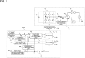
- Fig. 1 is a schematic diagram illustrating a circuit configuration and a control block diagram of an air-conditioning apparatus 100 and a motor control device 200 of an Example useful to explain the present invention.
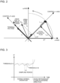
- Fig. 2 is a vector diagram of a configuration of magnetic-flux vector control by the motor control device 200 of the Example useful to explain the present invention.
- the air-conditioning apparatus 100 includes a smoothing capacitor 10, an inverter circuit 11, a current detecting unit 13, a gate driving circuit 14, an overcurrent protecting unit 15, a compressor 29 having a motor 30, a condenser 31, a pressure reducing unit 32, and an evaporator 33.
- the air-conditioning apparatus 100 obtains a direct-current voltage that is input to the inverter circuit 11 by performing AC-DC conversion on a voltage from an alternating-current power source.
- the alternating-current power is converted into direct-current power by a circuit such as a diode bridge circuit.
- the smoothing capacitor 10 smooths ripples in the voltage after rectification.
- the inverter circuit 11 converts a direct-current voltage smoothed by the smoothing capacitor 10 into an alternating-current voltage and drives the motor 30.
- the inverter circuit 11 includes six switching devices 12 and six return-current diodes, and a reverse current (return current) flows through each of the return-current diodes when a corresponding one of the switching devices 12 is turned off.
- Each of the switching devices 12 has a semiconductor device such as an IGBT (Insulated Gate Bipolar Transistor).
- the switching devices 12 of the inverter circuit 11 are each composed of a device made of silicon carbide, gallium nitride or related materials, or diamond, for example.
- An output line of the inverter 11 is connected to the motor 30 and the current detecting unit 13 is disposed on the output line of the inverter circuit 11.
- the current detecting unit 13 detects all phases of three-phase currents flowing through the motor 30 and outputs a voltage or current signal in accordance with a current flowing through the output line of the inverter circuit 11.
- the current detecting unit 13 includes, for example, a current sensor that detects the current flowing through the motor 30.
- An instantaneous current value of the motor 30 detected by the current detecting unit 13 is digitized and read into a microcomputer, for example.
- the current detecting unit 13 may detect two-phase currents flowing through the motor 30 and derive a remaining one-phase current by summing the instantaneous values of the detected two-phase currents followed by multiplying the sum by -1.
- the current detecting unit 13 may generally be any of those that detect a magnetic flux in accordance with a current flow and convert the magnetic flux into a voltage, as long as a device such as a Hall element is incorporated therein.
- the overcurrent protecting unit 15 has a function of protecting the inverter circuit 11 by causing the air-conditioning apparatus 100 to temporarily stop operating when the current detected by the current detecting unit 13 exceeds a predetermined reference current.
- a phenomenon called demagnetization which weakens a magnetic flux of a permanent magnet in a rotor, occurs.
- demagnetization which weakens a magnetic flux of a permanent magnet in a rotor
- the reference current is determined, for example, in accordance with a demagnetization level of the motor 30 from the viewpoint of reducing or eliminating the aforementioned phenomenon called demagnetization.
- the reference current is also determined, for example, from the viewpoint of preventing the loss in the IGBT in the inverter circuit 11 from increasing.
- the overcurrent protecting unit 15 causes the air-conditioning apparatus 100 to temporarily stop operating, for example, when one of the aforementioned reference currents, whichever is smaller, is exceeded.
- the overcurrent protecting unit 15 is constructed using hardware components such as an electronic circuit or configured to perform software protection in which a current detection signal is input to a microcomputer, for example, which performs a digital conversion process. If the overcurrent protecting unit 15 is configured to perform the software protection, the overcurrent protecting unit 15 allows greater design flexibility because the threshold can be changed freely and a variety of calculation processes can be performed.
- the compressor 29 is a variable capacity compressor that compresses suctioned refrigerant and converts the refrigerant into high-temperature and high-pressure refrigerant, which is discharged from the compressor 29.
- the compressor 29 includes the motor 30.
- the motor 30 is constructed using a motor having a structure that incorporates a permanent magnet into a rotor (permanent magnet synchronous motor), which has a high energy-saving capacity, for example.
- the condenser 31 is a heat exchanger that condenses and liquefies the refrigerant discharged from the compressor 29.
- the refrigerant condensed and liquefied in the condenser 31 expands under a reduced pressure in the pressure reducing unit 32.
- the evaporator 33 evaporates and gasifies the refrigerant flowing from the pressure reducing unit 32.
- the compressor 29, the condenser 31, the pressure reducing unit 32, and the evaporator 33 are connected in succession by using refrigerant pipes and constitute a refrigeration cycle apparatus.
- the motor control device 200 includes a coordinate conversion unit 20, a rotation speed command generating unit 21, an integrating unit 22, a ⁇ -axis current command table 23, a frequency compensating unit 24, a voltage command calculating unit 25, a load-torque detecting unit 26, a current correcting unit 27, and an inverse coordinate conversion unit 28.
- the motor control device 200 controls the gate driving circuit 14 so that the motor 30 is controlled to obtain a required rotation speed in response to a current detected by the current detecting unit 13.
- a voltage is applied between the gate and emitter terminals of the IGBT in response to a signal output from the gate driving circuit 14, continuity between the collector and the emitter of the IGBT is established and a voltage is applied to the motor 30.
- the motor control device 200 detects a magnetic-pole phase of the permanent magnet by using a device such as a magnetic-flux sensor and controls the current on the basis of the magnetic-pole phase.
- a device such as a magnetic-flux sensor
- installing a magnetic-flux sensor into a place that is under a high-temperature and high-pressure condition, such as the interior of the motor 30, is not easy, and thus the air-conditioning apparatus 100 usually performs position-sensorless control without using a position sensor.
- Example 2 a magnetic-flux vector control method, in which an output voltage is controlled so that a primary magnetic flux generated in the motor is maintained at a constant value on a fixed axis, will be described in the following as an example of the position-sensorless control of the permanent magnet synchronous motor.
- the coordinate conversion unit 20 converts three-phase alternating currents flowing through the motor 30 detected by the current detecting unit 13 into a direct current on the basis of a phase ⁇ that synchronizes with a rotation speed of the motor.
- the coordinate conversion unit 20 outputs, on the basis of the phase ⁇ , an excitation component current I ⁇ , which generates a magnetic flux that emerges in the motor 30, and a torque component current I ⁇ , which is orthogonal to the excitation component current I ⁇ and contributes to a torque component of the motor 30.
- the direction of the magnetic flux of the permanent magnet of the motor 30 is designated as the d-axis
- the axis orthogonal to the d-axis is designated as the q-axis.
- the ⁇ - and ⁇ -axes used for the present magnetic-flux vector control operate by generating control axes that differ from the d- and q-axes by an angle of ⁇ .
- the rotation speed command generating unit 21 performs a calculation of a command value for the rotation speed of the motor 30 so that the air-conditioning apparatus 100 obtains a required refrigeration capacity.
- the rotation speed command generating unit 21 also performs a calculation so that the rotation speed of the motor 30 increases in a situation such as requiring a larger refrigeration capacity, for example, cooling operation under a high-temperature outdoor-air condition.
- the rotation speed command generating unit 21 includes a microcomputer, for example.
- the rotation speed command generating unit 21 may control not only the rotation speed of the motor 30 but also a rotation speed of a motor of a fan and various actuators including an opening degree of an expansion valve in the pressure reducing unit 32.
- N represents the number of rotations of the motor per minute, expressed in [min -1 ].
- f represents a frequency of the voltage applied to the motor, that is, the frequency [Hz] of the three-phase alternating-current voltage generated by the inverter circuit 11 in the case of the Example.
- p represents the number of magnetic poles of the motor 30 (hereinafter referred to as the number of poles).
- the rotation speed of the motor is proportional to the frequency of the inverter output voltage and inversely proportional to the number of poles. This indicates that the rotation speed of the motor can be controlled by controlling the frequency of the inverter output voltage.
- the motor control device 200 controls the inverter circuit 11 so as to generate a voltage having a frequency proportional to the command value for the rotation speed generated by the rotation speed command generating unit 21.
- phase ⁇ which synchronizes with the rotation speed of the motor 30, is obtained by integrating with respect to time an electric angular velocity that is derived from the aforementioned command value of the rotation speed command generating unit 21. Then, in the Example, the final phase ⁇ can be obtained by using the frequency compensating unit 24 described below so that the motor 30 rotates with further stability.
- the frequency compensating unit 24 has a role of compensating the angular velocity ⁇ so that the motor 30 can follow the phase with stability with respect to the command value for the rotation speed described above even when load torque changes.
- the frequency compensating unit 24 performs negative-feedback control using a value proportional to the torque component current I ⁇ to compensate the frequency so that the phase of the ⁇ - and ⁇ - axes, which are the control axes, is delayed to match the actual magnetic-pole position. In this way, the motor 30 can be operated with stable rotation without losing track of the magnetic-pole position and going out of synchronization.
- the angular velocity ⁇ represents the final angular velocity that has been compensated by the frequency compensating unit 24.
- f is an inverter output frequency determined in accordance with the command for the compressor rotation speed.
- K is a proportional gain for the amount of frequency compensation with respect to the torque component current I ⁇ .
- the angular velocity ⁇ can follow a torque variation with an enhanced sensitivity as the frequency compensation gain K increases, too large a value for the frequency compensation gain K causes unstable control.
- the most suitable value is determined in advance. Values of the frequency compensation gain K may be maintained in a table stored in a device such as a microcomputer so that the most suitable values are obtained for various operation patterns.
- a value obtained using the coordinate conversion is used here for the torque component current l ⁇ , a filtration process may be performed, so that only a component having a certain time constant is effective.
- a new term is added to the motor voltage equation for the feedback of an error ⁇ err in the magnetic flux that is a difference between a magnetic-flux command value ⁇ * and a calculated primary magnetic flux ⁇ so that a total magnetic flux generated in the motor 30 is equal to a predetermined reference value on the ⁇ -axis. Then, voltage command values V ⁇ * and V ⁇ * that are to be generated on the ⁇ - and ⁇ - axes are obtained. The calculation is performed using the magnetic-flux command value ⁇ * for the primary magnetic flux generated in the motor 30, I ⁇ and I ⁇ obtained by the aforementioned operation, resistance and inductance components and an induced voltage constant of the motor 30, and the angular velocity ⁇ .
- the resistance and inductance components, the induced voltage constant, and other parameters of the motor 30 are intrinsic values that are measured in advance, and the measured values are maintained in a microcomputer, for example.
- the magnetic-flux vector control is performed so as to maintain the magnetic flux at a certain constant value on the ⁇ -axis.
- the magnetic-flux command values ⁇ * that provide the most efficient operating condition of the motor 30 are measured in advance and maintained in a table, which enables efficient driving of the motor 30.
- the torque component current I ⁇ is adopted as an input for tabulation, and the most suitable magnetic-flux command value ⁇ * for each torque component current I ⁇ is determined and maintained.
- the rotation speed of the motor 30 may be adopted as the input for tabulation, and the most suitable magnetic-flux command value ⁇ * for the motor 30 is determined and maintained.
- the magnetic-flux vector control may be configured by using I ⁇ as a command value to approximate the calculation based on the magnetic-flux command value ⁇ * .
- the inverse coordinate conversion unit 28 converts a direct-current value on the two axes into three-phase alternating-current values in accordance with the voltage command values on the ⁇ - and ⁇ -axes obtained by the voltage command calculating unit 25 and obtains voltage command values Vu * , Vv * , and Vw * of three-phase alternating current.
- the phase ⁇ used in the inverse coordinate conversion unit 28 is the same phase ⁇ as used in the coordinate conversion unit 20. Because the voltage command values Vu * , Vv * , and Vw * are three-phase sinusoidal voltage signals, these values become PWM (Pulse Width Modulation) signals to switch on and off the IGBT devices of the inverter circuit 11.
- the gate driving circuit 14 amplifies PWM signals generated in accordance with Vu * , Vv * , and Vw * , obtains signals of approximately ⁇ 15 V, and applies each of the voltages between the gate and the emitter of a corresponding one of the IGBT devices to drive the gate of the corresponding IGBT device of the inverter circuit 11.
- the primary magnetic flux of the motor 30 is controlled to be maintained at a predetermined constant value and on the ⁇ -axis using the aforementioned configuration, so that the compressor 29 can be driven at a rotation speed such as to obtain a required refrigeration capacity. In this way, the rotation speed of the motor 30 can be controlled without using a magnetic-pole position sensor for the permanent magnet synchronous motor.
- the load-torque detecting unit 26 As described above, with an increase in the load torque, the torque component current I ⁇ increases. This indicates that a state of the load torque can be detected by I ⁇ . In the case that I ⁇ exceeds a predetermined value, the motor 30 is controlled to avoid going out of synchronization by increasing the current from the command value determined by the ⁇ -axis current command table 23 described above, that is, by increasing I ⁇ .
- the threshold for I ⁇ is determined so that the current correcting unit 27 remains inactive in a normal operation range of the compressor 29 and is activated when load torque increases outside the operation range of the compressor 29.
- the threshold for I ⁇ thus determined does not cause the command values in the ⁇ -axis current command table 23 to be corrected while the compressor 29 remains in the normal operation range.
- the air-conditioning apparatus 100 maintains high-efficiency operation while the compressor 29 remains in the normal operation range, and avoids an out-of-synchronization state only in the case of operation under a high load-torque condition such as the case in which the refrigerant flows in the reverse direction.
- the air-conditioning apparatus 100 continues to operate in this way.
- Overload operation in which the load torque of the motor 30 reaches a maximum, for example, is included in the normal operation range of the compressor 29.
- Conditions outside the operation range of the compressor 29 include the case in which the refrigerant flows in the reverse direction and is suctioned by the compressor 29, for example.
- the threshold for I ⁇ may be variable and configured to be determined by the amount of variation in I ⁇ . In this way, early detection of a tendency toward an increase in the load torque can be performed in advance with noise or the like detected in error, and the compressor 29 can be operated in the normal operation range.
- the present control is performed by a device such as a microcomputer, for example, which determines the amount of variation in I ⁇ by calculating I ⁇ in every control cycle, storing in a memory the detected value of I ⁇ that is currently detected and the preceding value in every sampling period, and calculating a difference between the two as indicated by Expression (3).
- a device such as a microcomputer, for example, which determines the amount of variation in I ⁇ by calculating I ⁇ in every control cycle, storing in a memory the detected value of I ⁇ that is currently detected and the preceding value in every sampling period, and calculating a difference between the two as indicated by Expression (3).
- amount of variation in I ⁇ currently detected value of I ⁇ ⁇ preceding value
- Fig. 3 is a conceptual diagram illustrating an example of determination of a threshold for the load-torque detecting unit 26 in the motor control device 200 of the Example useful to explain the present invention.
- the horizontal axis of Fig. 3 represents time, and the vertical axis of Fig. 3 represents the torque component current I ⁇ .
- Threshold A is set at a value equal to or larger than a maximum value of I ⁇ in the normal operation range of the compressor 29.
- Threshold B is set at a value equal to or larger than a maximum amount of variation in the torque component current I ⁇ generated by torque ripples of the motor 30 in the normal operation range.
- the values of threshold A and threshold B are predetermined, for example, by performing test operation in advance using an actual apparatus and measuring each value.
- the amount of variation in the torque component current I ⁇ is obtained by calculating a difference between detected values per sampling period, which are detected as described above by the microcomputer, for example.
- Threshold B for the amount of variation is set to a positive value because it is commonly known that the torque component current I ⁇ increases with an increase in the load torque of the motor 30.
- the current correcting unit 27 increases the current flowing through the motor 30 with an increase in the load torque detected by the load-torque detecting unit 26.
- the current correcting unit 27 operates so as to further increase the current command value from the current command value based on the ⁇ -axis current command table 23 in the situation in which the load torque detected by the load-torque detecting unit 26 is outside the normal operation range of the compressor 29.
- An increase in the current command value is achieved, for example, by adding a predetermined constant current command value in every control cycle.
- the current correcting unit 27 controls the current command value that has been increased to decrease to the previous I ⁇ current command value obtained from the ⁇ -axis current command table 23.
- the motor control device 200 of Embodiment 1 of the present invention can increase the ⁇ -axis current command value, thereby increasing the current flowing through the motor 30, which heats the motor 30, and the liquefied refrigerant in the compressor 29 can be vaporized.
- the motor control device 200 that controls the motor 30 includes the load-torque detecting unit 26 that detects the load torque of the motor 30 and the current correcting unit 27 that controls the current flowing through the motor 30 in accordance with the information detected by the load-torque detecting unit 26, and the current correcting unit 27 increases the current flowing through the motor 30 in accordance with the increase in the load torque detected by the load-torque detecting unit 26.
- the load-torque detecting unit 26 detects the locking state at an early stage, and the current correcting unit 27 is activated and increases the current flowing through the motor 30, increasing the ⁇ -axis current and activating the overcurrent protecting unit 15.
- the air-conditioning apparatus 100 can be stopped safely before the temperature increase of the stator windings exceeds the allowable limit for the windings. Consequently, the motor 30 is capable of continuing operation by avoiding going out of synchronization in the case of the increase in the load torque of the motor 30.
- the magnetic-flux vector control has been described as an example of the position-sensorless control of the permanent magnet synchronous motor, other position-sensorless control may be adopted, and the command value for each current may be corrected when the load-torque detecting unit 26 detects the load torque outside the normal operation range of the compressor 29.
- the motor 30 is also capable of continuing operation by avoiding going out of synchronization in the case of the increase in the load torque of the motor 30.
- the increase in the ⁇ -axis current command value causes an excessive current to flow through the motor 30, and the motor 30 is heated.
- the reverse refrigerant flow can be suppressed, and the air-conditioning apparatus 100 can be stopped in the case of locking failure of the motor 30.
- a load-torque detecting unit 26 employs a root-mean-square value calculating unit 26a, an unbalancing calculating unit 26b, and a power factor calculating unit 26c in place of I ⁇ obtained using the coordinate conversion.
- a load-torque detecting unit 26 employs a root-mean-square value calculating unit 26a, an unbalancing calculating unit 26b, and a power factor calculating unit 26c in place of I ⁇ obtained using the coordinate conversion.
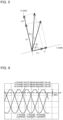
- Fig. 4 is a schematic diagram illustrating a circuit configuration and a control block diagram of an air-conditioning apparatus 100 and a motor control device 200 of the Embodiment of the present invention.
- Fig. 5 is a vector diagram of a configuration of magnetic-flux vector control by the motor control device 200 of the Embodiment of the present invention.
- the motor control device 200 includes the root-mean-square value calculating unit 26a, the unbalancing calculating unit 26b, and the power factor calculating unit 26c.
- the root-mean-square value calculating unit 26a calculates a root-mean-square (RMS) value of each phase current of the motor 30.
- RMS root-mean-square
- the formula for calculating the root-mean-square value is given by averaging the square of an alternating current over one cycle followed by calculating the square root of the averaged value.
- values sampled at every control cycle of the microcomputer can be used for approximate calculation.
- a root-mean-square value can be calculated by dividing an instantaneous peak value by ⁇ 2 for a sinusoidal-wave alternating current, and the root-mean-square value of current may be derived by using this formula from an instantaneous peak value obtained in one cycle, on which peak-hold operation is performed.
- the unbalancing calculating unit 26b calculates an unbalanced value by calculating a difference in the root-mean-square value between individual phase currents that flow through the motor 30.
- the root-mean-square values of phase currents are calculated by the root-mean-square value calculating unit 26a.
- ⁇ U - V, ⁇ V - W, and ⁇ W - U are substantially 0 A.
- the balance of inductance between the phases becomes disrupted, and the three-phase alternating currents of the motor 30 become unbalanced ( Fig. 7 ).
- the unbalanced values of the root-mean-square values of phase currents further increase during open-phase operation in which stator windings or wirings connecting the motor 30 and the inverter circuit 11, for example, are disconnected ( Fig. 8 ).
- the power factor calculating unit 26c calculates a power factor of the motor 30.
- An increase in the load torque of the motor 30 and a state of the motor 30 when locked are detected based on an instantaneous current value of the motor 30, unbalanced values of the root-mean-square values of phase currents, and a phase difference between the voltage and the current, that is, the power factor of the motor 30.
- the current correcting unit 27 determines that the motor 30 is malfunctioning with the load torque of the motor 30 increased and avoids an out-of-synchronization state of the motor 30 by controlling the motor 30 so as to increase the ⁇ -axis current command value.
- the first reference value is set to a value larger than the differences in the root-mean-square value between the individual phase currents in the normal operation range of the motor 30, which are measured in advance, for example, in test operation using the actual apparatus.
- measuring at the same time unbalanced values of the root-mean-square values of phase currents in the case that the motor 30 is actually locked enables determination of the threshold for more certain detection of malfunctioning.
- the current correcting unit 27 determines that the motor 30 is malfunctioning with the load torque of the motor 30 increased and avoids an out-of-synchronization state of the motor 30 by controlling the motor 30 so as to increase the ⁇ -axis current command value.
- the second reference value is smaller than or equal to a minimum power factor in the normal operation range of the motor 30, which is measured in advance, for example, in test operation using the actual apparatus. It is known that the power factor degrades when the motor 30 is subjected to a locking failure, for example.
- the configuration such as in the Embodiment enables more certain detection of a rapid variation in the load torque of the compressor 29 or a failure state of the motor 30.
- the power factor can be derived from a phase difference between the voltage applied to the motor 30 and the current.
- the voltage applied to the motor 30 is a vector sum of V ⁇ and V ⁇
- a device such as a microcomputer can be used to calculate a phase difference ⁇ v of the vector sum of the voltages with respect to the ⁇ - and ⁇ -axes.
- the vector sum of V ⁇ and V ⁇ can be determined in accordance with the Pythagorean theorem, and the phase difference of the voltage vector can be obtained by Expression (6) ( Fig. 5 ).
- ⁇ v Tan ⁇ 1 V ⁇ / V ⁇
- the current flowing through the motor 30 can also be derived from a vector sum of the currents I ⁇ and I ⁇ .
- the phase difference of the current vector can be obtained by Expression (7) in a manner similar to the above description of the phase difference of the voltage vector.
- the current flowing through the motor 30 may be controlled using the unbalancing calculating unit 26b that calculates unbalancing between the root-mean-square values of phase currents of the compressor 29 and the power factor calculating unit 26c that calculates the power factor of the motor 30.
- the current correcting unit 27 may determine that the motor 30 is malfunctioning and avoid an out-of-synchronization state of the motor 30 by controlling the motor 30 so as to increase the ⁇ -axis current command value.
- the motor control device 200 determines that the motor 30 has returned to normal rotation. In the case of detecting with more certainty that the motor 30 has returned to normal rotation, the motor control device 200 determines that the motor 30 has returned to normal rotation, for example, when the value calculated by the root-mean-square value calculating unit 26a becomes smaller than or equal to a predetermined value. Then, when the motor 30 returns to normal rotation, the current correcting unit 27 decreases the increased ⁇ -axis current command value to the normal current command value.
- the load-torque detecting unit 26 further includes the root-mean-square value calculating unit 26a that calculates the root-mean-square value of current of the motor 30 and the unbalancing calculating unit 26b that calculates the unbalanced value of the root-mean-square values of three-phase currents calculated by the root-mean-square value calculating unit 26a. Then, the current correcting unit 27 increases the current flowing through the motor 30, determining that the load torque has increased when the unbalanced value calculated by the unbalancing calculating unit 26b is larger than the first reference value.
- the motor 30 can avoid going out of synchronization in the case of a rapid change in the load torque of the motor 30, and even when the motor 30 is malfunctioning for some reason, increasing the ⁇ -axis current enables early activation of the overcurrent protecting unit 15 and a safe halt of the air-conditioning apparatus 100. In this way, reliability of the apparatus can be ensured.
- the load-torque detecting unit 26 further includes the power factor calculating unit 26c that calculates the power factor of the motor 30, and the current correcting unit 27 increases the current flowing through the motor 30, determining that the load torque has increased when the power factor of the motor 30 calculated by the power factor calculating unit 26c is smaller than or equal to the second reference value.
- the motor 30 can avoid going out of synchronization in the case of a rapid change in the load torque of the motor 30, and even when the motor 30 is malfunctioning for some reason, increasing the ⁇ -axis current enables early activation of the overcurrent protecting unit 15 and a safe halt of the air-conditioning apparatus 100. In this way, reliability of the apparatus can be ensured.
- the load-torque detecting unit 26 further includes the root-mean-square value calculating unit 26a that calculates the root-mean-square value of current of the motor 30, the unbalancing calculating unit 26b that calculates the unbalanced value of the root-mean-square values of three-phase currents calculated by the root-mean-square value calculating unit 26a, and the power factor calculating unit 26c that calculates the power factor of the motor 30.
- the current correcting unit 27 increases the current flowing through the motor 30, determining that the load torque has increased when the unbalanced value calculated by the unbalancing calculating unit 26b is larger than the first reference value, or when the power factor of the motor 30 calculated by the power factor calculating unit 26c is smaller than or equal to the second reference value.
- the motor 30 can avoid going out of synchronization in the case of a rapid change in the load torque of the motor 30, and even when the motor 30 is malfunctioning for some reason, increasing the ⁇ -axis current enables early activation of the overcurrent protecting unit 15 and a safe halt of the air-conditioning apparatus. In this way, reliability of the apparatus can be ensured.
Landscapes
- Engineering & Computer Science (AREA)
- Power Engineering (AREA)
- Control Of Ac Motors In General (AREA)
- Control Of Motors That Do Not Use Commutators (AREA)
Claims (9)
- Motorsteuerungsvorrichtung (200), die einen Motor (30) steuert, umfassend:eine Lastmoment-Erfassungseinheit (26), die eingerichtet ist, das Lastmoment des Motors (30) zu erfassen; undeine Stromkorrektureinheit (27), die eingerichtet ist, einen durch den Motor (30) fließenden Strom in Übereinstimmung mit einem Anstieg des von der Lastmoment-Erfassungseinheit (26) erfassten Lastmoments zu erhöhen,wobei die Last-Drehmoment-Erfassungseinheit (26) umfasst
eine Leistungsfaktor-Berechnungseinheit (26c), die eingerichtet ist, einen Leistungsfaktor des Motors (30) zu berechnen,wobei die Stromkorrektureinheit (27) den durch den Motor (30) fließenden Strom erhöht,die Motorsteuerungsvorrichtung (20) dadurch gekennzeichnet ist, dass die Stromkorrektureinheit (27) feststellt, dass das Lastmoment angestiegen ist, wenn der von der Leistungsfaktorberechnungseinheit (26c) berechnete Leistungsfaktor des Motors (30) kleiner oder gleich einem Referenzwert ist. - Motorsteuerungsvorrichtung (200), die einen Motor (30) steuert, umfassend:eine Lastmoment-Erfassungseinheit (26), die eingerichtet ist, das Lastmoment des Motors (30) zu erfassen; undeine Stromkorrektureinheit (27), die eingerichtet ist, einen durch den Motor (30) fließenden Strom in Übereinstimmung mit einem Anstieg des von der Lastmoment-Erfassungseinheit (26) erfassten Lastmoments zu erhöhen,wobei die Motorsteuerungsvorrichtung (20) dadurch gekennzeichnet ist, dass die Lastmoment-Erfassungseinheit (26) umfassteine Quadratischer-Mittelwert-Berechnungseinheit (26a), die eingerichtet ist, einen quadratischen Mittelwert von jedem der Dreiphasenströme des Motors (30) zu berechnen, undeine Unsymmetrieberechnungseinheit (26b), die eingerichtet ist, einen Unsymmetriewert zu berechnen, indem sie eine Differenz im quadratischen Mittelwert zwischen einzelnen Phasenströmen berechnet, die durch den Motor (30) fließen, der von der Quadratischer-Mittelwert-Berechnungseinheit (26a) berechnet wurde,wobei die Stromkorrektureinheit (27) den durch den Motor (30) fließenden Strom erhöht, bestimmend, dass das Lastmoment angestiegen ist, wenn der von der Unsymmetrieberechnungseinheit (26b) berechnete Unsymmetriewert größer als ein Referenzwert ist.
- Motorsteuerungsvorrichtung (200) nach Anspruch 1, wobei
die Last-Drehmoment-Erfassungseinheit (26) umfassteine Quadratischer-Mittelwert-Berechnungseinheit (26a), die eingerichtet ist, einen quadratischen Mittelwert von jedem der Dreiphasenströme des Motors (30) zu berechnen, undeine Unsymmetrieberechnungseinheit (26b), die eingerichtet ist, einen Unsymmetriewert zu berechnen, indem sie eine Differenz im quadratischen Mittelwert zwischen einzelnen Phasenströmen berechnet, die durch den Motor (30) fließen, der von der Quadratischer-Mittelwert-Berechnungseinheit (26a) berechnet wurde, unddie Stromkorrektureinheit (27) erhöhtden durch den Motor (30) fließenden Strom, bestimmend, dass sich das Lastmoment erhöht hat, wenn der von der Unsymmetrieberechnungseinheit (26b) berechnete Unsymmetriewert größer als ein Referenzwert ist. - Motorsteuerungsvorrichtung (200) nach einem der Ansprüche 1 bis 3, umfassend:
eine lagesensorlose Steuerung, die eingerichtet ist, einen Gesamtmagnetfluss im Motor (30) so zu steuern, dass er auf einem Referenzwert gehalten wird. - Kompressor (29), umfassend:
den Motor (30), der von der Motorsteuerungsvorrichtung (200) nach einem der Ansprüche 1 bis 4 gesteuert wird. - Klimaanlage (100), umfassend:den Kompressor (29) nach Anspruch 5;eine Stromerfassungseinheit (13), die eingerichtet ist, einen Strom des Motors (30) zu erfassen; undeine Überstrom-Schutzeinheit (15), die eingerichtet ist, die Motorsteuerungsvorrichtung (200) anzuhalten, wenn der von der Stromerfassungseinheit (13) erfasste Strom größer als oder gleich einem Referenzstrom ist.
- Klimaanlage (100), umfassend:den Kompressor (29) nach Anspruch 5;einen Glättungskondensator (10), der eingerichtet ist, eine gleichgerichtete Gleichspannung zu glätten, die aus einer Spannung von einer dreiphasigen Wechselstromquelle gleichgerichtet wird; undeine Wechselrichterschaltung (11), die eingerichtet ist, die durch den Glättungskondensator (10) geglättete Gleichspannung in eine Wechselspannung umzuwandeln.
- Klimaanlage (100) nach Anspruch 7, wobeieine Schaltvorrichtung der Wechselrichterschaltung (11) umfassteine Vorrichtung aus Siliziumkarbid, eine Vorrichtung aus Galliumnitrid oder verwandten Materialien oder eine Vorrichtung aus Diamant.
- Klimaanlage (100), umfassend:
einen Kältekreislauf, der den Kompressor (29) nach Anspruch 5, einen Kondensator (31), eine Druckreduziereinheit (32), einen Verdampfer (33) und eine Kältemittelleitung, die den Kompressor (29), den Kondensator (31), die Druckreduziereinheit (32) und den Verdampfer (33) miteinander verbindet, enthält.
Applications Claiming Priority (1)
| Application Number | Priority Date | Filing Date | Title |
|---|---|---|---|
| PCT/JP2015/069948 WO2017009907A1 (ja) | 2015-07-10 | 2015-07-10 | モータ制御装置、圧縮機、及び空気調和機 |
Publications (3)
| Publication Number | Publication Date |
|---|---|
| EP3322087A1 EP3322087A1 (de) | 2018-05-16 |
| EP3322087A4 EP3322087A4 (de) | 2018-07-11 |
| EP3322087B1 true EP3322087B1 (de) | 2025-05-21 |
Family
ID=57757849
Family Applications (1)
| Application Number | Title | Priority Date | Filing Date |
|---|---|---|---|
| EP15898223.1A Active EP3322087B1 (de) | 2015-07-10 | 2015-07-10 | Motorsteuerungsvorrichtung, verdichter und klimaanlage |
Country Status (3)
| Country | Link |
|---|---|
| EP (1) | EP3322087B1 (de) |
| JP (1) | JP6410939B2 (de) |
| WO (1) | WO2017009907A1 (de) |
Families Citing this family (5)
| Publication number | Priority date | Publication date | Assignee | Title |
|---|---|---|---|---|
| WO2020031526A1 (ja) * | 2018-08-07 | 2020-02-13 | 日本電産株式会社 | 駆動制御装置、駆動装置およびパワーステアリング装置 |
| CN114977904B (zh) * | 2022-04-29 | 2025-12-19 | 江苏金彭集团有限公司 | 基于负载估计和动态调速的pmsm无传感启动方法 |
| CN115095968B (zh) * | 2022-07-08 | 2024-06-18 | 北京小米移动软件有限公司 | 转矩补偿控制方法、装置和存储介质 |
| WO2024106339A1 (ja) * | 2022-11-15 | 2024-05-23 | 株式会社日立製作所 | 電力変換装置、電力変換回路の制御方法 |
| CN118920958B (zh) * | 2024-10-10 | 2025-02-14 | 中联重科股份有限公司 | 电缸控制方法、装置、电动作业机械及机器可读存储介质 |
Family Cites Families (11)
| Publication number | Priority date | Publication date | Assignee | Title |
|---|---|---|---|---|
| JP2001169597A (ja) * | 1999-12-03 | 2001-06-22 | Yaskawa Electric Corp | 同期電動機の駆動電流直流成分の補正方法および補正装置 |
| JP2005059786A (ja) * | 2003-08-18 | 2005-03-10 | Koyo Seiko Co Ltd | 電動パワーステアリング装置 |
| JP4578142B2 (ja) * | 2004-04-22 | 2010-11-10 | 日本電産シバウラ株式会社 | ブラシレスdcモータの駆動装置 |
| JP4641179B2 (ja) * | 2004-11-25 | 2011-03-02 | 川崎重工業株式会社 | 同期モータの制御方法および制御装置 |
| AU2006347701B2 (en) * | 2006-08-31 | 2010-11-18 | Mitsubishi Electric Corporation | Electric motor driving device, and compressor driving device |
| JP4930085B2 (ja) * | 2007-02-08 | 2012-05-09 | 株式会社富士通ゼネラル | 位相検出方法、位相検出装置、同期モータの制御方法、および同期モータの制御装置 |
| JP5175887B2 (ja) * | 2010-03-23 | 2013-04-03 | 株式会社東芝 | モータ制御装置及び電気機器 |
| US8487557B2 (en) * | 2011-02-15 | 2013-07-16 | General Electric Company | Use of motor protection system to protect process operation |
| JP5253593B2 (ja) * | 2012-02-14 | 2013-07-31 | 三菱電機株式会社 | 空気調和機 |
| JP5851303B2 (ja) * | 2012-03-28 | 2016-02-03 | 三菱電機株式会社 | 冷凍サイクル装置および室外熱源ユニット |
| CN103701372B (zh) * | 2012-09-27 | 2017-07-04 | 比亚迪股份有限公司 | 一种同步电机的失步检测方法 |
-
2015
- 2015-07-10 EP EP15898223.1A patent/EP3322087B1/de active Active
- 2015-07-10 JP JP2017528018A patent/JP6410939B2/ja active Active
- 2015-07-10 WO PCT/JP2015/069948 patent/WO2017009907A1/ja not_active Ceased
Also Published As
| Publication number | Publication date |
|---|---|
| JPWO2017009907A1 (ja) | 2018-02-22 |
| WO2017009907A1 (ja) | 2017-01-19 |
| JP6410939B2 (ja) | 2018-10-24 |
| EP3322087A4 (de) | 2018-07-11 |
| EP3322087A1 (de) | 2018-05-16 |
Similar Documents
| Publication | Publication Date | Title |
|---|---|---|
| EP2465195B1 (de) | Steuerung und verfahren für den übergang zwischen steuerwinkeln | |
| EP3322087B1 (de) | Motorsteuerungsvorrichtung, verdichter und klimaanlage | |
| JP6333563B2 (ja) | インバータ制御装置およびそれを用いた冷凍装置 | |
| US11601076B2 (en) | Motor driving apparatus and refrigeration cycle equipment | |
| US11424698B2 (en) | Motor control device and air-conditioning device | |
| JP2003079183A (ja) | 同期電動機の脱調検出装置及び同期電動機の脱調検出方法及び密閉形圧縮機の駆動装置及びファンモータの駆動装置 | |
| TWI488424B (zh) | 同步電動機之驅動裝置,及使用其之冷凍裝置、空氣調節機、冰箱,以及同步電動機之驅動方法 | |
| EP2448110A2 (de) | Kühlvorrichtung und Steuerung für einen Permanentmagnetsynchronmotor | |
| US20210203256A1 (en) | Motor driver and refrigeration cycle equipment | |
| US11711040B2 (en) | Motor driving apparatus and refrigeration cycle equipment | |
| JP6929434B2 (ja) | 電動機駆動装置及び冷凍サイクル適用機器 | |
| US10270380B2 (en) | Power converting apparatus and heat pump device | |
| US20260029469A1 (en) | State estimation device, drive system, refrigeration system, fan system, and state estimation method | |
| US20210281196A1 (en) | Air conditioner | |
| US20250007443A1 (en) | State determination device, motor drive system, freezing system, fan system, and state determination method | |
| US11632068B2 (en) | Motor driving device and air conditioner | |
| JP7595807B2 (ja) | モータ駆動装置及び冷凍サイクル装置 | |
| JP2003111480A (ja) | 電動機駆動装置 | |
| US11264924B2 (en) | Motor driving apparatus and refrigeration cycle equipment | |
| US20240396486A1 (en) | Power conversion apparatus, motor drive apparatus, and refrigeration cycle application apparatus | |
| CN118232769A (zh) | 电动机的驱动控制装置、电动机装置、制冷空调机、风扇装置以及驱动控制方法 | |
| JP6925527B2 (ja) | モータ駆動装置、モータ駆動装置の制御装置、モータ駆動装置の制御方法、及び空気調和機 | |
| JP2008164183A (ja) | 冷凍サイクル装置 | |
| US20260022878A1 (en) | State estimation device, drive system, refrigeration system, fan system, state estimation method, and state estimation program | |
| US20260029182A1 (en) | Control device, refrigeration system, control method, and control program |
Legal Events
| Date | Code | Title | Description |
|---|---|---|---|
| STAA | Information on the status of an ep patent application or granted ep patent |
Free format text: STATUS: THE INTERNATIONAL PUBLICATION HAS BEEN MADE |
|
| PUAI | Public reference made under article 153(3) epc to a published international application that has entered the european phase |
Free format text: ORIGINAL CODE: 0009012 |
|
| STAA | Information on the status of an ep patent application or granted ep patent |
Free format text: STATUS: REQUEST FOR EXAMINATION WAS MADE |
|
| 17P | Request for examination filed |
Effective date: 20180123 |
|
| AK | Designated contracting states |
Kind code of ref document: A1 Designated state(s): AL AT BE BG CH CY CZ DE DK EE ES FI FR GB GR HR HU IE IS IT LI LT LU LV MC MK MT NL NO PL PT RO RS SE SI SK SM TR |
|
| AX | Request for extension of the european patent |
Extension state: BA ME |
|
| A4 | Supplementary search report drawn up and despatched |
Effective date: 20180608 |
|
| RIC1 | Information provided on ipc code assigned before grant |
Ipc: H02P 29/024 20160101ALI20180604BHEP Ipc: H02P 6/15 20160101ALI20180604BHEP Ipc: H02P 29/00 20160101AFI20180604BHEP Ipc: H02P 23/26 20160101ALI20180604BHEP |
|
| DAV | Request for validation of the european patent (deleted) | ||
| DAX | Request for extension of the european patent (deleted) | ||
| STAA | Information on the status of an ep patent application or granted ep patent |
Free format text: STATUS: EXAMINATION IS IN PROGRESS |
|
| 17Q | First examination report despatched |
Effective date: 20210517 |
|
| GRAP | Despatch of communication of intention to grant a patent |
Free format text: ORIGINAL CODE: EPIDOSNIGR1 |
|
| STAA | Information on the status of an ep patent application or granted ep patent |
Free format text: STATUS: GRANT OF PATENT IS INTENDED |
|
| INTG | Intention to grant announced |
Effective date: 20250117 |
|
| GRAS | Grant fee paid |
Free format text: ORIGINAL CODE: EPIDOSNIGR3 |
|
| GRAA | (expected) grant |
Free format text: ORIGINAL CODE: 0009210 |
|
| STAA | Information on the status of an ep patent application or granted ep patent |
Free format text: STATUS: THE PATENT HAS BEEN GRANTED |
|
| AK | Designated contracting states |
Kind code of ref document: B1 Designated state(s): AL AT BE BG CH CY CZ DE DK EE ES FI FR GB GR HR HU IE IS IT LI LT LU LV MC MK MT NL NO PL PT RO RS SE SI SK SM TR |
|
| REG | Reference to a national code |
Ref country code: GB Ref legal event code: FG4D |
|
| REG | Reference to a national code |
Ref country code: CH Ref legal event code: EP |
|
| REG | Reference to a national code |
Ref country code: DE Ref legal event code: R096 Ref document number: 602015091718 Country of ref document: DE |
|
| REG | Reference to a national code |
Ref country code: IE Ref legal event code: FG4D |
|
| PGFP | Annual fee paid to national office [announced via postgrant information from national office to epo] |
Ref country code: GB Payment date: 20250626 Year of fee payment: 11 |
|
| REG | Reference to a national code |
Ref country code: NL Ref legal event code: MP Effective date: 20250521 |
|
| PG25 | Lapsed in a contracting state [announced via postgrant information from national office to epo] |
Ref country code: FI Free format text: LAPSE BECAUSE OF FAILURE TO SUBMIT A TRANSLATION OF THE DESCRIPTION OR TO PAY THE FEE WITHIN THE PRESCRIBED TIME-LIMIT Effective date: 20250521 Ref country code: ES Free format text: LAPSE BECAUSE OF FAILURE TO SUBMIT A TRANSLATION OF THE DESCRIPTION OR TO PAY THE FEE WITHIN THE PRESCRIBED TIME-LIMIT Effective date: 20250521 Ref country code: PT Free format text: LAPSE BECAUSE OF FAILURE TO SUBMIT A TRANSLATION OF THE DESCRIPTION OR TO PAY THE FEE WITHIN THE PRESCRIBED TIME-LIMIT Effective date: 20250922 |
|
| PGFP | Annual fee paid to national office [announced via postgrant information from national office to epo] |
Ref country code: DE Payment date: 20250624 Year of fee payment: 11 |
|
| REG | Reference to a national code |
Ref country code: LT Ref legal event code: MG9D |
|
| PG25 | Lapsed in a contracting state [announced via postgrant information from national office to epo] |
Ref country code: NO Free format text: LAPSE BECAUSE OF FAILURE TO SUBMIT A TRANSLATION OF THE DESCRIPTION OR TO PAY THE FEE WITHIN THE PRESCRIBED TIME-LIMIT Effective date: 20250821 Ref country code: GR Free format text: LAPSE BECAUSE OF FAILURE TO SUBMIT A TRANSLATION OF THE DESCRIPTION OR TO PAY THE FEE WITHIN THE PRESCRIBED TIME-LIMIT Effective date: 20250822 |
|
| PG25 | Lapsed in a contracting state [announced via postgrant information from national office to epo] |
Ref country code: NL Free format text: LAPSE BECAUSE OF FAILURE TO SUBMIT A TRANSLATION OF THE DESCRIPTION OR TO PAY THE FEE WITHIN THE PRESCRIBED TIME-LIMIT Effective date: 20250521 Ref country code: PL Free format text: LAPSE BECAUSE OF FAILURE TO SUBMIT A TRANSLATION OF THE DESCRIPTION OR TO PAY THE FEE WITHIN THE PRESCRIBED TIME-LIMIT Effective date: 20250521 |
|
| PG25 | Lapsed in a contracting state [announced via postgrant information from national office to epo] |
Ref country code: BG Free format text: LAPSE BECAUSE OF FAILURE TO SUBMIT A TRANSLATION OF THE DESCRIPTION OR TO PAY THE FEE WITHIN THE PRESCRIBED TIME-LIMIT Effective date: 20250521 |
|
| PG25 | Lapsed in a contracting state [announced via postgrant information from national office to epo] |
Ref country code: HR Free format text: LAPSE BECAUSE OF FAILURE TO SUBMIT A TRANSLATION OF THE DESCRIPTION OR TO PAY THE FEE WITHIN THE PRESCRIBED TIME-LIMIT Effective date: 20250521 |
|
| PG25 | Lapsed in a contracting state [announced via postgrant information from national office to epo] |
Ref country code: RS Free format text: LAPSE BECAUSE OF FAILURE TO SUBMIT A TRANSLATION OF THE DESCRIPTION OR TO PAY THE FEE WITHIN THE PRESCRIBED TIME-LIMIT Effective date: 20250821 |
|
| PG25 | Lapsed in a contracting state [announced via postgrant information from national office to epo] |
Ref country code: IS Free format text: LAPSE BECAUSE OF FAILURE TO SUBMIT A TRANSLATION OF THE DESCRIPTION OR TO PAY THE FEE WITHIN THE PRESCRIBED TIME-LIMIT Effective date: 20250921 |
|
| PG25 | Lapsed in a contracting state [announced via postgrant information from national office to epo] |
Ref country code: LV Free format text: LAPSE BECAUSE OF FAILURE TO SUBMIT A TRANSLATION OF THE DESCRIPTION OR TO PAY THE FEE WITHIN THE PRESCRIBED TIME-LIMIT Effective date: 20250521 |
|
| REG | Reference to a national code |
Ref country code: AT Ref legal event code: MK05 Ref document number: 1797686 Country of ref document: AT Kind code of ref document: T Effective date: 20250521 |
|
| PG25 | Lapsed in a contracting state [announced via postgrant information from national office to epo] |
Ref country code: AT Free format text: LAPSE BECAUSE OF FAILURE TO SUBMIT A TRANSLATION OF THE DESCRIPTION OR TO PAY THE FEE WITHIN THE PRESCRIBED TIME-LIMIT Effective date: 20250521 Ref country code: SM Free format text: LAPSE BECAUSE OF FAILURE TO SUBMIT A TRANSLATION OF THE DESCRIPTION OR TO PAY THE FEE WITHIN THE PRESCRIBED TIME-LIMIT Effective date: 20250521 Ref country code: DK Free format text: LAPSE BECAUSE OF FAILURE TO SUBMIT A TRANSLATION OF THE DESCRIPTION OR TO PAY THE FEE WITHIN THE PRESCRIBED TIME-LIMIT Effective date: 20250521 |
|
| PG25 | Lapsed in a contracting state [announced via postgrant information from national office to epo] |
Ref country code: CZ Free format text: LAPSE BECAUSE OF FAILURE TO SUBMIT A TRANSLATION OF THE DESCRIPTION OR TO PAY THE FEE WITHIN THE PRESCRIBED TIME-LIMIT Effective date: 20250521 |
|
| PG25 | Lapsed in a contracting state [announced via postgrant information from national office to epo] |
Ref country code: EE Free format text: LAPSE BECAUSE OF FAILURE TO SUBMIT A TRANSLATION OF THE DESCRIPTION OR TO PAY THE FEE WITHIN THE PRESCRIBED TIME-LIMIT Effective date: 20250521 |
|
| PG25 | Lapsed in a contracting state [announced via postgrant information from national office to epo] |
Ref country code: RO Free format text: LAPSE BECAUSE OF FAILURE TO SUBMIT A TRANSLATION OF THE DESCRIPTION OR TO PAY THE FEE WITHIN THE PRESCRIBED TIME-LIMIT Effective date: 20250521 Ref country code: SK Free format text: LAPSE BECAUSE OF FAILURE TO SUBMIT A TRANSLATION OF THE DESCRIPTION OR TO PAY THE FEE WITHIN THE PRESCRIBED TIME-LIMIT Effective date: 20250521 |
|
| PG25 | Lapsed in a contracting state [announced via postgrant information from national office to epo] |
Ref country code: IT Free format text: LAPSE BECAUSE OF FAILURE TO SUBMIT A TRANSLATION OF THE DESCRIPTION OR TO PAY THE FEE WITHIN THE PRESCRIBED TIME-LIMIT Effective date: 20250521 |
|
| REG | Reference to a national code |
Ref country code: CH Ref legal event code: H13 Free format text: ST27 STATUS EVENT CODE: U-0-0-H10-H13 (AS PROVIDED BY THE NATIONAL OFFICE) Effective date: 20260224 Ref country code: DE Ref legal event code: R097 Ref document number: 602015091718 Country of ref document: DE |
|
| PG25 | Lapsed in a contracting state [announced via postgrant information from national office to epo] |
Ref country code: LU Free format text: LAPSE BECAUSE OF NON-PAYMENT OF DUE FEES Effective date: 20250710 |
|
| REG | Reference to a national code |
Ref country code: BE Ref legal event code: MM Effective date: 20250731 |
|
| PLBE | No opposition filed within time limit |
Free format text: ORIGINAL CODE: 0009261 |
|
| STAA | Information on the status of an ep patent application or granted ep patent |
Free format text: STATUS: NO OPPOSITION FILED WITHIN TIME LIMIT |
|
| REG | Reference to a national code |
Ref country code: CH Ref legal event code: L10 Free format text: ST27 STATUS EVENT CODE: U-0-0-L10-L00 (AS PROVIDED BY THE NATIONAL OFFICE) Effective date: 20260402 |
|
| PG25 | Lapsed in a contracting state [announced via postgrant information from national office to epo] |
Ref country code: BE Free format text: LAPSE BECAUSE OF NON-PAYMENT OF DUE FEES Effective date: 20250731 |
|
| PG25 | Lapsed in a contracting state [announced via postgrant information from national office to epo] |
Ref country code: FR Free format text: LAPSE BECAUSE OF NON-PAYMENT OF DUE FEES Effective date: 20250721 |
|
| PG25 | Lapsed in a contracting state [announced via postgrant information from national office to epo] |
Ref country code: CH Free format text: LAPSE BECAUSE OF NON-PAYMENT OF DUE FEES Effective date: 20250731 |
|
| 26N | No opposition filed |
Effective date: 20260224 |