EP3322089B1 - Structure de fixation au logement pour module photovoltaïque à concentration, module photovoltaïque à concentration, panneau photovoltaïque à concentration et dispositif photovoltaïque à concentration - Google Patents
Structure de fixation au logement pour module photovoltaïque à concentration, module photovoltaïque à concentration, panneau photovoltaïque à concentration et dispositif photovoltaïque à concentration Download PDFInfo
- Publication number
- EP3322089B1 EP3322089B1 EP16821182.9A EP16821182A EP3322089B1 EP 3322089 B1 EP3322089 B1 EP 3322089B1 EP 16821182 A EP16821182 A EP 16821182A EP 3322089 B1 EP3322089 B1 EP 3322089B1
- Authority
- EP
- European Patent Office
- Prior art keywords
- bottom plate
- concentrator photovoltaic
- nut
- photovoltaic module
- bolt
- Prior art date
- Legal status (The legal status is an assumption and is not a legal conclusion. Google has not performed a legal analysis and makes no representation as to the accuracy of the status listed.)
- Not-in-force
Links
Images



Classifications
-
- H—ELECTRICITY
- H02—GENERATION; CONVERSION OR DISTRIBUTION OF ELECTRIC POWER
- H02S—GENERATION OF ELECTRIC POWER BY CONVERSION OF INFRARED RADIATION, VISIBLE LIGHT OR ULTRAVIOLET LIGHT, e.g. USING PHOTOVOLTAIC [PV] MODULES
- H02S20/00—Supporting structures for PV modules
- H02S20/10—Supporting structures directly fixed to the ground
-
- H—ELECTRICITY
- H02—GENERATION; CONVERSION OR DISTRIBUTION OF ELECTRIC POWER
- H02S—GENERATION OF ELECTRIC POWER BY CONVERSION OF INFRARED RADIATION, VISIBLE LIGHT OR ULTRAVIOLET LIGHT, e.g. USING PHOTOVOLTAIC [PV] MODULES
- H02S20/00—Supporting structures for PV modules
- H02S20/30—Supporting structures being movable or adjustable, e.g. for angle adjustment
-
- H—ELECTRICITY
- H02—GENERATION; CONVERSION OR DISTRIBUTION OF ELECTRIC POWER
- H02S—GENERATION OF ELECTRIC POWER BY CONVERSION OF INFRARED RADIATION, VISIBLE LIGHT OR ULTRAVIOLET LIGHT, e.g. USING PHOTOVOLTAIC [PV] MODULES
- H02S20/00—Supporting structures for PV modules
- H02S20/30—Supporting structures being movable or adjustable, e.g. for angle adjustment
- H02S20/32—Supporting structures being movable or adjustable, e.g. for angle adjustment specially adapted for solar tracking
-
- H—ELECTRICITY
- H02—GENERATION; CONVERSION OR DISTRIBUTION OF ELECTRIC POWER
- H02S—GENERATION OF ELECTRIC POWER BY CONVERSION OF INFRARED RADIATION, VISIBLE LIGHT OR ULTRAVIOLET LIGHT, e.g. USING PHOTOVOLTAIC [PV] MODULES
- H02S30/00—Structural details of PV modules other than those related to light conversion
- H02S30/10—Frame structures
-
- H—ELECTRICITY
- H02—GENERATION; CONVERSION OR DISTRIBUTION OF ELECTRIC POWER
- H02S—GENERATION OF ELECTRIC POWER BY CONVERSION OF INFRARED RADIATION, VISIBLE LIGHT OR ULTRAVIOLET LIGHT, e.g. USING PHOTOVOLTAIC [PV] MODULES
- H02S40/00—Components or accessories in combination with PV modules, not provided for in groups H02S10/00 - H02S30/00
- H02S40/20—Optical components
- H02S40/22—Light-reflecting or light-concentrating means
-
- H—ELECTRICITY
- H02—GENERATION; CONVERSION OR DISTRIBUTION OF ELECTRIC POWER
- H02S—GENERATION OF ELECTRIC POWER BY CONVERSION OF INFRARED RADIATION, VISIBLE LIGHT OR ULTRAVIOLET LIGHT, e.g. USING PHOTOVOLTAIC [PV] MODULES
- H02S40/00—Components or accessories in combination with PV modules, not provided for in groups H02S10/00 - H02S30/00
- H02S40/30—Electrical components
- H02S40/36—Electrical components characterised by special electrical interconnection means between two or more PV modules, e.g. electrical module-to-module connection
-
- H—ELECTRICITY
- H10—SEMICONDUCTOR DEVICES; ELECTRIC SOLID-STATE DEVICES NOT OTHERWISE PROVIDED FOR
- H10F—INORGANIC SEMICONDUCTOR DEVICES SENSITIVE TO INFRARED RADIATION, LIGHT, ELECTROMAGNETIC RADIATION OF SHORTER WAVELENGTH OR CORPUSCULAR RADIATION
- H10F19/00—Integrated devices, or assemblies of multiple devices, comprising at least one photovoltaic cell covered by group H10F10/00, e.g. photovoltaic modules
- H10F19/80—Encapsulations or containers for integrated devices, or assemblies of multiple devices, having photovoltaic cells
-
- H—ELECTRICITY
- H10—SEMICONDUCTOR DEVICES; ELECTRIC SOLID-STATE DEVICES NOT OTHERWISE PROVIDED FOR
- H10F—INORGANIC SEMICONDUCTOR DEVICES SENSITIVE TO INFRARED RADIATION, LIGHT, ELECTROMAGNETIC RADIATION OF SHORTER WAVELENGTH OR CORPUSCULAR RADIATION
- H10F77/00—Constructional details of devices covered by this subclass
- H10F77/40—Optical elements or arrangements
- H10F77/42—Optical elements or arrangements directly associated or integrated with photovoltaic cells, e.g. light-reflecting means or light-concentrating means
- H10F77/484—Refractive light-concentrating means, e.g. lenses
-
- H—ELECTRICITY
- H10—SEMICONDUCTOR DEVICES; ELECTRIC SOLID-STATE DEVICES NOT OTHERWISE PROVIDED FOR
- H10F—INORGANIC SEMICONDUCTOR DEVICES SENSITIVE TO INFRARED RADIATION, LIGHT, ELECTROMAGNETIC RADIATION OF SHORTER WAVELENGTH OR CORPUSCULAR RADIATION
- H10F77/00—Constructional details of devices covered by this subclass
- H10F77/40—Optical elements or arrangements
- H10F77/42—Optical elements or arrangements directly associated or integrated with photovoltaic cells, e.g. light-reflecting means or light-concentrating means
-
- Y—GENERAL TAGGING OF NEW TECHNOLOGICAL DEVELOPMENTS; GENERAL TAGGING OF CROSS-SECTIONAL TECHNOLOGIES SPANNING OVER SEVERAL SECTIONS OF THE IPC; TECHNICAL SUBJECTS COVERED BY FORMER USPC CROSS-REFERENCE ART COLLECTIONS [XRACs] AND DIGESTS
- Y02—TECHNOLOGIES OR APPLICATIONS FOR MITIGATION OR ADAPTATION AGAINST CLIMATE CHANGE
- Y02E—REDUCTION OF GREENHOUSE GAS [GHG] EMISSIONS, RELATED TO ENERGY GENERATION, TRANSMISSION OR DISTRIBUTION
- Y02E10/00—Energy generation through renewable energy sources
- Y02E10/50—Photovoltaic [PV] energy
- Y02E10/52—PV systems with concentrators
Definitions
- the present invention relates to a mounting structure for a concentrator photovoltaic module housing, a concentrator photovoltaic module, a concentrator photovoltaic panel, and a concentrator photovoltaic apparatus.
- Some concentrator photovoltaic apparatuses have a basic unit in which: small compound semiconductor elements each having a high power generation efficiency are used as power generating elements; and sunlight concentrated through Fresnel lenses are caused to be incident on the power generating elements.
- a concentrator photovoltaic module is obtained by arranging a large number of such basic units in a matrix shape in one housing.
- a concentrator photovoltaic panel is obtained by further arranging a plurality of the modules.
- a housing to be used in the above-mentioned concentrator photovoltaic module there is a housing that includes: a bottom plate where a plurality of power generating elements are arrayed; and a frame body standing along the outer edge of the bottom plate and holding a concentrating member such that the concentrating member faces the bottom plate.
- the frame body (excluding the bottom plate) is formed from resin in order to reduce the weight and the cost (for example, see PATENT LITERATURE 1).
- US 2014/0230883 A1 discloses a concentrator photovoltaic module.
- JP-2011/196067 discloses a solar cell array.
- PATENT LITERATURE 1 Japanese Laid-Open Patent Publication No. 2013-84670
- the present disclosure provides a mounting structure for a concentrator photovoltaic module housing in accordance with claim 1.
- a mounting structure for a concentrator photovoltaic module housing is a mounting structure for a concentrator photovoltaic module housing configured to be used in a concentrator photovoltaic module, the concentrator photovoltaic module including: a plurality of power generating elements; and a concentrating member configured to concentrate sunlight toward each of the plurality of power generating elements, the mounting structure including: a bottom plate formed from an electric conductor and having the plurality of power generating elements arrayed thereat; a side wall frame made of resin, the side wall frame standing along an outer edge of the bottom plate and configured to hold the concentrating member so as to face the bottom plate; a support member being a grounded electric conductor, the support member configured to be in contact with the bottom plate to support the concentrator photovoltaic module; and a fastening member configured to fasten the support member and the bottom plate to each other thereby to fix the concentrator photovoltaic module to the support member, the fastening member being formed from an electric conductor thereby to serve as a path for electric
- a concentrator photovoltaic module uses the mounting structure for the concentrator photovoltaic module housing.
- a concentrator photovoltaic panel is formed by arranging a plurality of the concentrator photovoltaic modules.
- a concentrator photovoltaic apparatus includes: the concentrator photovoltaic panel; and a driving device configured to drive the concentrator photovoltaic panel to track movement of the sun while the concentrator photovoltaic panel is oriented toward a direction of the sun.
- the bottom plate (metal) located immediately below electric circuitry needs to be grounded. If the entirety of the housing is made of metal, it is easy to establish grounding from any part of the housing, but if the frame body other than the bottom plate is made of resin, it is not easy to establish grounding compared with a case where the entirety of the housing is made of metal.
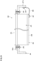
- FIG. 9 is a diagram showing one example of a structure in which a module using a housing of which frame body is formed from resin and of which bottom plate is formed from an electric conductor is mounted to a pedestal of a photovoltaic apparatus.
- a concentrator photovoltaic module 200 is fixed to a pedestal 201 of the photovoltaic apparatus.
- the concentrator photovoltaic module 200 includes: a housing 202; and a concentrating portion 203 configured to cover the opening of the housing 202.
- the housing 202 includes: a bottom plate 204 formed from an electric conductor and having power generating elements (not shown) arrayed therein; and a frame body 205 formed from resin.
- a flange portion 205a protruding from the outer face of the frame body 205 and the pedestal 201 are fastened together by means of bolts 206, whereby the concentrator photovoltaic module 200 of this example is fixed to the pedestal 201.
- a bolt 207 is attached to the outer face of the bottom plate 204.
- the bolt 207 fixes a conductor line 208 to the bottom plate 204.
- One end portion of the conductor line 208 is sandwiched by the bolt 207 and the bottom plate 204.
- the other end portion of the conductor line 208 is sandwiched by a bolt 209 mounted to a side plate portion 201a of the pedestal 201 and the side plate portion 201a.
- the conductor line 208 electrically connects the bottom plate 204 and the pedestal 201 to each other.
- the pedestal 201 is connected to another member having conductivity, and the bottom plate 204 is grounded through the conductor line 208 and the pedestal 201.
- the bottom plate is formed from an electric conductor, and the bottom plate and a conductor outside the housing are electrically connected to each other by a conductor line.
- the module 200 having the above configuration is fixed to a photovoltaic apparatus
- the work of connecting the conductor line 208 needs to be performed, and this results in complicated work.
- a large number of the modules 200 are fixed to the pedestal 201, and such complicated work is repeated many times, and consequently, a large number of man-hours are required.
- the present invention has been made in consideration of these circumstances, and an object of the present invention is to provide a mounting structure for a concentrator photovoltaic module housing, a concentrator photovoltaic module, a concentrator photovoltaic panel, and a concentrator photovoltaic apparatus which are capable of facilitating work of fixing the concentrator photovoltaic module to a power generation apparatus.
- the concentrator photovoltaic module According to the concentrator photovoltaic module, the concentrator photovoltaic panel, and the concentrator photovoltaic apparatus that have the configurations described above, work of fixing the concentrator photovoltaic module to the power generation apparatus can be facilitated.
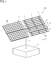
- FIG. 1 is a perspective view showing one example of a concentrator photovoltaic apparatus.
- a photovoltaic apparatus 100 includes: a photovoltaic panel 1 composed of two panels, i.e., left wing and right wing; and a pedestal 2 which supports the photovoltaic panel 1 at the rear face side thereof.
- FIG. 1 with respect to the panel 1 at the right on the drawing sheet, a part of the photovoltaic panel 1 is omitted in order to show the structure of the pedestal 2.
- the pedestal 2 includes: a base 3 and a support portion 4 standing on the base 3.
- the base 3 is fixed to the ground.
- the support portion 4 is vertically provided.
- a driving device 5 is provided at the support point for the photovoltaic panel 1, the support point being at the upper end of the support portion 4.
- the driving device 5 drives the photovoltaic panel 1 so as to rotate in the elevation direction, about a horizontally extending shaft 6.
- the driving device 5 drives the photovoltaic panel 1 so as to rotate in the azimuth direction, about the support portion 4.
- the driving device 5 is controlled by a control device (not shown).
- the control device has a drive circuit for driving built-in motors of the driving device 5. Through the operation of the motor (stepping motor) for each axis, the photovoltaic panel 1 can take an attitude at any angle for each of the azimuth and the elevation.
- the shaft 6, which is driven by the driving device 5, is provided with a plurality of beams 7 in a direction perpendicular to the shaft 6.
- the photovoltaic panel 1 is fixed to the upper side of the plurality of beams 7.
- the photovoltaic panel 1 is formed by arraying, in multiple rows, units 1U each formed by arranging 10 photovoltaic modules 1M horizontally in a row, for example.
- Each unit 1U includes: a plurality of the photovoltaic modules 1M; and a pair of frames 8 which integrally fix these photovoltaic modules 1M in a state of being aligned in a line.
- Each unit 1U is extended over the beams 7 and is fixed to the upper side of the beams 7.
- Each wing of the photovoltaic panel 1 is composed of 10 units 1U, for example. Accordingly, each wing of the photovoltaic panel 1 is formed by arranging 10 (in length) ⁇ 10 (in breadth) photovoltaic modules 1M in a matrix shape. Accordingly, 200 photovoltaic modules 1M are present in the photovoltaic panel 1 having the two wings.
- FIG. 2 is an enlarged perspective view (partially cut out) showing one example of a concentrator photovoltaic module (hereinafter, also simply referred to as module) 1M.
- the module 1M includes as major components: a housing 11 in a box shape; a flexible printed circuit 12 arranged in a plurality of rows at a bottom plate 15 of the housing 11; and a concentrating portion 13 mounted, like a cover, to a flange portion 11b of the housing 11.
- the flexible printed circuit 12 is obtained by providing a strip-film-shaped insulating base material with an electric conductor layer forming a circuit pattern. On top of this, cells 12c as power generating elements and other electronic components are mounted. As each cell 12c, a solar battery having heat resistance and a high power generation efficiency is used.
- the housing 11 includes: the bottom plate 15 where the flexible printed circuit 12 is disposed; and a side wall frame 16 standing along the outer edge of the bottom plate 15 and holding the concentrating portion 13 so as to face the bottom plate 15.
- the housing 11 will be described later in detail.
- the concentrating portion 13 is a Fresnel lens array and is formed by arranging, in a matrix shape, a plurality of (for example, 16 in length ⁇ 12 in breadth, 192 in total) Fresnel lenses 13f which each concentrates sunlight.
- the concentrating portion 13 can be obtained by, for example, forming a silicone resin film at a back surface (inside) of a glass plate as a base material. Each Fresnel lens 13f is formed at this resin film.
- the total number and arrangement of the Fresnel lenses 13f are the same as the total number and arrangement of the cells 12c, and the Fresnel lenses 13f and the cells 12c are in one-to-one correspondence with each other so that their optical axes are aligned with each other.
- FIG. 3 is a perspective view showing optical relationship between one Fresnel lens 13f and one cell 12c.
- the optical axis Ax of Fresnel lens 13f passes through the center of the cell 12c.
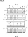
- FIG. 4 is a partial top view of the photovoltaic panel 1 shown in FIG. 1 .
- a plurality of the units 1U forming the photovoltaic panel 1 each include: a plurality of the modules 1M; and a pair of the frames 8 integrally fixing the plurality of the modules 1M in a state of being aligned in a line.
- Each of the pair of the frames 8 is a long member extending in the horizontal direction, and is formed from an electric conductor such as a structure steel, an aluminium alloy, or the like.
- the modules 1M are arranged in a line at a predetermined interval, between the pair of the frames 8, and are fixed to the pair of the frames 8.
- the length and breadth dimensions and the shape of the module 1M do not reflect those shown in FIG. 2 , and are expressed in a simplified manner as one example.
- the modules 1M are fixed to the pair of the frames 8, thereby forming a unit 1U.
- Each unit 1U is provided so as to be extended over the beams 7 such that the longitudinal direction of the unit 1U is parallel to the horizontal direction, and the unit 1U is fixed to the beams 7.
- Each unit 1U is fixed to the beams 7, by the frames 8 and the beams 7 are fixed to each other.
- each module 1M is supported and fixed by the frames 8 fixed to the beams 7, and the pair of the frames 8 form a support member which supports the modules 1M.
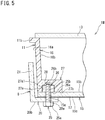
- FIG. 5 is a cross-sectional view showing a main part on a line V-V in FIG. 4 .
- the frame 8 is a member having an L-shape in cross-section.
- the frame 8 includes: a bottom portion 20 being in contact with the bottom plate 15 of the module 1M; and a side plate portion 21 standing along the outer edge of the bottom portion 20.
- the side plate portion 21 is formed so as to extend along an outer face 16a of the side wall frame 16 of the module 1M disposed between the pair of the frames 8.
- the side plate portion 21 is formed such that an appropriate gap is provided between the side plate portion 21 and the outer face 16a.
- the side plate portion 21 has a function as a guide that aligns the modules 1M in the longitudinal direction of the frames 8 when the modules 1M are fixed to the frames 8.
- each of the pair of the frames 8 is in contact with the bottom plate 15, thereby supporting the modules 1M.
- the pair of the frames 8 support the modules 1M while aligning the modules 1M in the longitudinal direction of the frame 8.
- the bottom plate 15 is formed from an aluminium alloy which is an electric conductor, and the side wall frame 16 is formed from resin, for example.
- the bottom plate 15 and the side wall frame 16 are formed as separate members, and the housing 11 is assembled by the bottom plate 15 and the side wall frame 16 being fixed to each other.
- the side wall frame 16 is formed in a rectangular frame shape by use of PBT (Poly Butylene Terephtalate) resin loaded with glass fibers, for example.
- the concentrating portion 13 is fixed to the opening at the one-side end face of the side wall frame 16.
- the bottom plate 15 is fixed to the side wall frame 16 so as to close the opening at the other-side end face of the side wall frame 16.
- the bottom plate 15 and the side wall frame 16 are bonded and fixed by use of a sealing agent having a bonding effect, whereby water and dust are prevented from entering the housing 11 through the joining portion between the bottom plate 15 and the side wall frame 16.
- a rust prevention film 17 is formed at an outer face 15c of the bottom plate 15 as a result of rust prevention treatment being performed thereon.
- the housing 11 includes a bolt 25 and a nut 26 for fastening the bottom portion 20 and the bottom plate 15.
- Each module 1M is fixed to the frames 8 as a result of the bottom portion 20 and the bottom plate 15 being fastened by the bolt 25 and the nut 26.
- the bolt 25 and the nut 26 are a general bolt and a general nut each formed from an electric conductor such as machine structure steel or stainless steel, for example.
- the bolt 25 and the nut 26 are mounted at each of four corners of the bottom plate 15.
- Each bolt 25 penetrates the bottom plate 15 and the bottom portion 20being in contact with each other, and is screwed into the corresponding nut 26 disposed inside the housing 11.
- the bolt 25 is screwed into the nut 26, and tightens the bottom plate 15 and the bottom portion 20 between the bolt 25 and the nut 26, thereby fastening the bottom plate 15 and the bottom portion 20.
- a hole portion 15a to be penetrated by the bolt 25 is formed in the bottom plate 15 of the module 1M.
- the hole portion 15a in the bottom plate 15 is formed at each of four corners of the housing 11 so as to allow communication between the inside and the outside of the housing 11.
- a hole portion 20a to be penetrated by the bolt 25 is also formed in the bottom portion 20 of each frame 8.
- the hole portion 20a in the bottom portion 20 is formed at a position that corresponds to each hole portion 15a when the module 1M is fixed to the frames 8.
- the hole portions 20a are formed at predetermined positions in the bottom portion 20 along the longitudinal direction of the frame 8.
- the bolt 25 is inserted in the hole portion 20a and the hole portion 15a from the bottom portion 20 side of the frame 8, penetrates the bottom portion 20 and the bottom plate 15, and is screwed into the nut 26.
- the nut 26 is held at an inner face 15b of the bottom plate 15 inside the housing 11, by a holding portion 27 protruding from an inner face 16b of the side wall frame 16.
- FIG. 6 is a diagram of the holding portion 27 in FIG. 5 , viewed from above. In FIG. 6 , the concentrating portion 13 is not shown.
- the holding portion 27 is formed integrally with the side wall frame 16, and is provided at each of four corners in the housing 11, so as to correspond to each hole portion 15a in the bottom plate 15.
- Each holding portion 27 is provided so as to protrude from the side wall frame 16 along the bottom plate 15.
- a holding hole 27a for accommodating the nut 26 is formed in the holding portion 27.
- the holding portion 27 holds the nut 26, with the nut 26 being accommodated in the holding hole 27a.
- the holding hole 27a is open at the bottom plate 15 side, and is formed in a hexagonal hole shape in cross-section so as to correspond to the outer shape of the nut 26.
- the dimensions in cross-section of the holding hole 27a is set to values slightly smaller than the dimensions of the outer shape of the nut 26 such that the holding hole 27a can hold the nut 26 pressed therein.
- the nut 26 is pressed (inserted) in the holding hole 27a and held therein. Since the holding hole 27a is formed in a hexagonal hole shape in cross-section, the nut 26 is held in a state where relative rotation of the nut 26 with respect to the bottom plate 15 is restricted.
- the depth dimension of the holding hole 27a is substantially the same as the thickness dimension of the nut 26.
- a clearance portion 28 which is a space for receiving a shank 25b of the bolt 25 is formed in the bottom face 27a1 of the holding hole 27a. Accordingly, even if the shank 25b of the bolt 25 screwed in the nut 26 protrudes from the nut 26, the protruding portion of the shank 25b can be received in the clearance portion 28.
- the holding portion 27 is bonded and fixed to the inner face 15b of the bottom plate 15 by means of the sealing agent bonding the bottom plate 15 and the side wall frame 16 together.
- a region R1 and a region R2 indicated by cross-hatching in FIG. 6 represent regions where the sealing agent is applied between the bottom plate 15 and the side wall frame 16 including the holding portion 27.
- a broken line H shows the edge of the bottom plate 15.
- the region R1 is a region where the sealing agent is applied, in a region where the end face of the side wall frame 16 and the bottom plate 15 are in contact with each other. By the sealing agent being applied to the region R1, the bottom plate 15 and the side wall frame 16 are bonded and fixed together.
- the region R2 is a region where the sealing agent is applied, between the lower face 27b of the holding portion 27 and the bottom plate 15.
- the region R2 has both ends thereof connected to the region R1, and surrounds the hole portion 15a having the bolt 25 inserted therein, along the periphery of the holding portion 27. In this manner, at the lower face 27b of the holding portion 27, the sealing agent is applied so as to isolate the hole portion 15a from the inside of the housing 11.
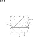
- FIG. 7 is an enlarged view of a portion where the sealing agent is applied between the holding portion 27 and the bottom plate 15 in FIG. 5 .
- a seal layer 29 formed by the applied sealing agent is present in the portion where the sealing agent is applied between the holding portion 27 and the bottom plate 15, a seal layer 29 formed by the applied sealing agent is present.
- the seal layer 29 bonds and fixes the holding portion 27 and the bottom plate 15 together, and closes the gap between the holding portion 27 and the bottom plate 15, thereby sealing the inside of the housing 11 from the outside.
- FIG. 7 the portion where the sealing agent is applied between the holding portion 27 and the bottom plate 15 is shown. However, also in the portion between the side wall frame 16 and the bottom plate 15 where the sealing agent is applied and where the side wall frame 16 and the bottom plate 15 are bonded and fixed by the sealing agent, a seal layer formed by the sealing agent is present.
- This seal layer seals the joining portion between the bottom plate 15 and the side wall frame 16, and prevents water and dust from entering the inside of the housing 11 through the joining portion.
- the bolt 25 is screwed into the nut 26 held inside the housing 11 as described above.
- the bolt 25 and the nut 26 tighten the bottom plate 15 and the bottom portion 20 between a head 25a and the nut 26, thereby fastening the bottom plate 15 and the bottom portion 20.
- the head 25a of the bolt 25 is in contact with a lower face 20b of the bottom portion 20 of the frame 8, and the nut 26 is in contact with the inner face 15b of the bottom plate 15.
- the bolt 25 and the nut 26 are each formed from an electric conductor.
- the frame 8 and the bottom plate 15 are each formed from an electric conductor.
- the frame 8 formed from an electric conductor is electrically connected to a ground line (not shown) of the photovoltaic apparatus 100.
- the bottom plate 15 is also formed from an electric conductor.
- the bolt 25 and the nut 26 electrically connect the frame 8 and the bottom plate 15 to each other. Accordingly, the bottom plate 15 is connected to the ground line of the photovoltaic apparatus 100, through the nut 26, the bolt 25, and the frame 8.
- the rust prevention film 17 is formed at the outer face 15c of the bottom plate 15, even when the bottom portion 20 of the frame 8 and the outer face 15c of the bottom plate 15 abut each other, there are cases where electric current is difficult to flow due to the presence of the rust prevention film 17.
- the bolt 25 and the nut 26 of the present embodiment are each an electric conductor, the bolt 25 and the nut 26 serve as a path for electric connection from the bottom plate 15 to the frame 8. Accordingly, grounding necessary for the concentrator photovoltaic module 1M is ensured. At this time, the resistance-to-ground of the bottom plate 15 is set to 0.1 ⁇ . or lower.
- the fixing is performed in the following procedure.
- the module 1M is disposed between a pair of the frames 8, and the hole portion 15a formed at each of four corners of the bottom plate 15 of the module 1M and the corresponding hole portion 20a formed in the bottom portion 20 of the corresponding frame 8 are aligned to each other. At this time, the bolt 25 is not yet screwed into the nut 26.
- the bolt 25 is inserted into the hole portion 20a and the hole portion 15a from the bottom portion 20 side of the frame 8, to be screwed into the nut 26 held inside the housing 11.
- the nut 26 is held by the holding portion 27, in a state where the one end face 26a is in contact with the inner face 15b of the bottom plate 15, and in a state where relative rotation of the nut 26 with respect to the bottom plate 15 is restricted at a position where a female screw portion 26b of the nut 26 is aligned with the hole portion 15a.
- the module 1M is disposed at the pair of the frames 8, and the hole portion 20a in the bottom portion 20 and the hole portion 15a in the bottom plate 15 are aligned to each other, it is possible to easily screw the bolt 25 into the nut 26, without requiring work of positioning the nut 26 or preventing the nut 26 from rotating together with the bolt 25.
- the bolt 25 is screwed into the nut 26 inside the housing 11, and the bottom plate 15 and the bottom portion 20 are tightened under a predetermined torque between the head 25a and the nut 26, whereby the bottom plate 15 and the bottom portion 20 are fastened.
- the head 25a of the bolt 25 can be made into contact with the bottom portion 20 of the frame 8, and further, the nut 26 can be made into contact with the bottom plate 15.
- the bottom plate 15 and the bottom portion 20 can be electrically connected to each other.
- a mounting structure for the housing 11 of the module 1M includes: the bottom plate 15 formed from an electric conductor and having a plurality of cells 12c (power generating elements) arrayed thereat; the side wall frame 16 made of resin, the side wall frame 16 standing along the outer edge of the bottom plate 15 and configured to hold the concentrating portion 13 so as to face the bottom plate 15; a pair of the frames 8 (support member) each being a grounded electric conductor, and each being in contact with the bottom plate 15 to support the module 1M; and the bolts 25 and the nuts 26, as a fastening member, configured to fasten the pair of the frames 8 and the bottom plate 15 to each other thereby to fix the module 1M to the pair of the frames 8, the bolts 25 and the nuts 26 each being an electric conductor thereby to serve as paths for electric connection from the bottom plate 15 to the pair of the frames 8.
- each bolt 25 and each nut 26 which fix the module 1M to the pair of the frames 8 serve as the paths for electric connection from the bottom plate 15 to the frames 8, and thus, if the module 1M is fixed to the pair of the frames 8 by means of the bolt 25 and the nut 26, grounding of the bottom plate 15 can be ensured at the same time.
- the fastening member which fastens the pair of the frames 8 and the bottom plate 15 thereby to fix the module 1M to the pair of the frames 8 the bolts 25 penetrating the bottom plate 15 and the frames 8, and the nuts 26 screwed with the bolts 25 thereby to fasten the bottom plate 15 and the frames 8 are used.
- the bottom plate 15 and the pair of the frames 8 can be easily fixed to each other.
- the bottom plate 15 of the housing 11 can be formed from a plate member made of an aluminium alloy. That is, if the hole portion 15a into which the bolt 25 is inserted is formed in a plate member made of an aluminium alloy, the plate member can be used as the bottom plate 15. Thus, the bottom plate 15 can be formed at a low cost.
- the bolt 25 can be inserted from outside of the housing 11, and the bolt 25 can be screwed into the nut 26 held inside the housing 11. Accordingly, when the bolt 25 is to be screwed into the nut 26, it is not necessary to position the nut 26 or prevent the nut 26 from rotating together with the bolt 25. Thus, the bolt 25 can be easily screwed into the nut 26. As a result, the bottom plate 15 and the pair of the frames 8 can be further easily fixed to each other.
- the holding portion 27 is formed integrally with the side wall frame 16, the holding portion 27 can be provided at a low cost and at a high accuracy.
- the nut 26 since the nut 26 is pressed to be held in the holding hole 27a of the holding portion 27, the nut 26 can be easily and reliably held in the holding portion 27.
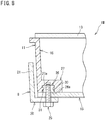
- FIG. 8 is a cross-sectional view of a main part of a module according to another embodiment.
- the housing 11 of the module 1M according to the present embodiment is different from the embodiment described above in that the holding portion 27 is formed with the nut 26 molded therein.
- the nut 26 when the side wall frame 16 of the housing 11 is to be formed, the nut 26 is set in a die for forming the side wall frame 16, and is held in the holding portion 27at the same time when the side wall frame 16 is formed.
- the nut 26 of the present embodiment has a groove portion 30 formed in the side face thereof.
- the groove portion 30 is formed, for example, by being cut by use of a highspeed cutter or the like.
- resin enters the groove portion 30 during formation of the side wall frame 16, and protrudes from the inner wall of the holding hole 27a, whereby a protrusion 31 which engages with the groove portion 30 is formed.
- the protrusion 31 serves as a stopper, the nut 26 is firmly held in the holding hole 27a.
- the nut 26 of the present embodiment is molded and held in the holding portion 27, and thus, the nut 26 can be reliably held.
- the groove portion 30 is formed in the nut 26 .
- the nut 26 is provided with a protruding portion or a recessed portion that engages with the holding portion 27 when the nut 26 is molded in the holding portion 27.
- protrusions and recesses having a wedge shape in cross-section, a large number of holes, or the like may be formed at the surface of the nut 26.
- a linear-shaped groove portion that can be formed by use of a cutter or the like is easy to form, and thus, such a groove portion is advantageous in reducing the cost.
- the groove portion 30 is formed in the nut 26 .
- the nut 26 may be molded without having the groove portion 30 or the like formed therein.
- the present invention is not limited to the embodiments described above.
- an example case has been shown in which: the nut 26 is held in the holding portion 27 inside the housing 11, and the bolt 25 is inserted from outside of the housing 11 to be screwed into the nut 26 inside the housing 11, whereby the frame 8 and the bottom plate 15 are fastened.
- a configuration may be employed in which: the head 25a of the bolt 25 is held in the holding portion 27 inside the housing 11, the shank 25b of the bolt 25 is caused to protrude through the hole portion 15a and the hole portion 20a to the outside of the housing 11, and then, the nut 26 is screwed onto the shank 25b of the bolt 25 from outside of the housing 11.
Landscapes
- Life Sciences & Earth Sciences (AREA)
- Sustainable Development (AREA)
- Photovoltaic Devices (AREA)
Claims (7)
- Structure de montage pour un logement de module photovoltaïque de concentrateur (11) configurée pour être utilisée dans un module photovoltaïque de concentrateur (1M), le module photovoltaïque de concentrateur (1M) incluant : plusieurs éléments de production d'énergie (12c) ; et un élément de concentration (13) configuré pour concentrer la lumière du soleil vers chacun des plusieurs éléments de production d'énergie (12c), la structure de montage comprenant :une plaque de fond (15) formée à partir d'un conducteur électrique et présentant les plusieurs éléments de production d'énergie (12c) alignés sur celle-ci ;un cadre de paroi latéral (16) constitué de résine, le cadre de paroi latérale (16) se trouvant le long d'un bord externe de la plaque de fond (15) et configuré pour supporter l'élément de concentration (13) afin de faire face à la plaque de fond (15) ;un élément de support (8) étant un conducteur électrique mis à la terre, l'élément de support (8) configuré pour être en contact avec la plaque de fond (15) pour supporter le module photovoltaïque de concentrateur (1M) ; etun élément de fixation (25, 26) configuré pour fixer l'élément de support (8) et la plaque de fond (15) l'un à l'autre pour fixer par-là le module photovoltaïque de concentrateur (1M) à l'élément de support (8), l'élément de fixation (25, 26) étant formé d'un conducteur électrique pour servir par-là comme une trajectoire pour une connexion électrique à partir de la plaque de fond (15) jusqu'à l'élément de support (8), dans laquellel'élément de fixation (25, 26) inclut :un boulon (25) configuré pour pénétrer dans la plaque de fond (25) et l'élément de support (8) ; etun écrou (26) configuré pour être vissé avec le boulon (25) pour fixer la plaque de fond (15) et l'élément de support (8), dans laquelleune portion de support (27) supportant l'écrou (26) ou une tête du boulon (25a) à l'intérieur du logement (11) et sur une face interne de la plaque de fond (15b) est formée de manière intégrale avec une face interne du cadre de paroi latéral (16b).
- Structure de montage pour le logement de module photovoltaïque de concentrateur (11) selon la revendication 1, dans laquelle
l'écrou (26) ou la tête du boulon (25a) est moulé et supporté dans la portion de support (27). - Structure de montage pour le logement de module photovoltaïque de concentrateur (11) selon la revendication 1, dans laquelle
l'écrou (26) ou la tête du boulon (25a) est inséré et maintenu dans la portion de support (27). - Structure de montage pour le logement de module photovoltaïque de concentrateur (11) selon l'une quelconque des revendications 1 à 3, dans laquelle
une couche de scellement (29) pour un scellement à l'intérieur du module photovoltaïque de concentrateur (1M) est formée entre la portion de maintien (27) et la face interne de la plaque de fond (15b). - Module photovoltaïque de concentrateur (1M) utilisant la structure de montage pour le logement de module photovoltaïque de concentrateur (11) selon la revendication 1.
- Panneau photovoltaïque de concentrateur (1) formé en disposant plusieurs des modules photovoltaïques de concentrateur (1M) selon la revendication 5.
- Appareil photovoltaïque de concentrateur (100) comprenant :le panneau photovoltaïque de concentrateur (1) selon la revendication 6 ; etun dispositif de commande (5) configuré pour commander au panneau photovoltaïque de concentrateur (1) un mouvement de suivi du soleil alors que le panneau photovoltaïque de concentrateur (1) est orienté vers une direction du soleil.
Applications Claiming Priority (2)
| Application Number | Priority Date | Filing Date | Title |
|---|---|---|---|
| JP2015137406A JP6569340B2 (ja) | 2015-07-09 | 2015-07-09 | 集光型太陽光発電モジュール用筐体取付構造、集光型太陽光発電モジュール、集光型太陽光発電パネル、及び集光型太陽光発電装置 |
| PCT/JP2016/067610 WO2017006712A1 (fr) | 2015-07-09 | 2016-06-14 | Structure de fixation au logement pour module photovoltaïque à concentration, module photovoltaïque à concentration, panneau photovoltaïque à concentration et dispositif photovoltaïque à concentration |
Publications (3)
| Publication Number | Publication Date |
|---|---|
| EP3322089A1 EP3322089A1 (fr) | 2018-05-16 |
| EP3322089A4 EP3322089A4 (fr) | 2019-02-20 |
| EP3322089B1 true EP3322089B1 (fr) | 2020-10-28 |
Family
ID=57685189
Family Applications (1)
| Application Number | Title | Priority Date | Filing Date |
|---|---|---|---|
| EP16821182.9A Not-in-force EP3322089B1 (fr) | 2015-07-09 | 2016-06-14 | Structure de fixation au logement pour module photovoltaïque à concentration, module photovoltaïque à concentration, panneau photovoltaïque à concentration et dispositif photovoltaïque à concentration |
Country Status (8)
| Country | Link |
|---|---|
| US (1) | US10312852B2 (fr) |
| EP (1) | EP3322089B1 (fr) |
| JP (1) | JP6569340B2 (fr) |
| CN (1) | CN107852129B (fr) |
| AU (1) | AU2016288958B2 (fr) |
| ES (1) | ES2829257T3 (fr) |
| MA (1) | MA42905B1 (fr) |
| WO (1) | WO2017006712A1 (fr) |
Families Citing this family (12)
| Publication number | Priority date | Publication date | Assignee | Title |
|---|---|---|---|---|
| USD783521S1 (en) * | 2014-12-19 | 2017-04-11 | Jln Solar, Inc. | Solar panel mount |
| US11326742B2 (en) | 2017-07-31 | 2022-05-10 | Fujikin Incorporated | Valve |
| JP7021671B2 (ja) * | 2017-08-07 | 2022-02-17 | 住友電気工業株式会社 | 集光型太陽光発電モジュール、集光型太陽光発電パネル、集光型太陽光発電装置、及び集光型太陽光発電モジュールの製造方法 |
| MA51183A (fr) | 2017-12-14 | 2020-10-21 | Sumitomo Electric Industries | Procédé de détection de mauvais état de montage de module, et réseau |
| AU2019230301A1 (en) | 2018-03-05 | 2020-09-24 | Sumitomo Electric Industries, Ltd. | Method for Manufacturing Concentrator Photovoltaic Module, and Transport Jig |
| WO2019216167A1 (fr) | 2018-05-08 | 2019-11-14 | 住友電気工業株式会社 | Système d'évaluation et procédé d'évaluation |
| JPWO2019220992A1 (ja) | 2018-05-15 | 2021-07-08 | 住友電気工業株式会社 | 太陽光発電装置の製造方法、太陽光発電装置の製造治具および太陽光発電装置の製造装置 |
| CN109738003A (zh) * | 2019-01-29 | 2019-05-10 | 阜阳师范学院 | 一种便于安装的农业物联网环境测控装置 |
| CN114362657A (zh) * | 2021-12-30 | 2022-04-15 | 江苏舜大新能源科技有限公司 | 一种光伏组件固定结构及其安装拆卸方法 |
| CN118413184A (zh) * | 2022-11-18 | 2024-07-30 | 浙江凯阳电力工程有限公司 | 一种光伏组件聚光装置 |
| CN116131730A (zh) | 2023-01-30 | 2023-05-16 | 上海晨科太阳能科技有限公司 | 一种光伏面板的安装结构 |
| PL74074Y1 (pl) * | 2023-04-24 | 2025-09-08 | Blachotrapez Spolka Z Ograniczona Odpowiedzialnoscia | Konstrukcja montażowa dla paneli fotowoltaicznych |
Family Cites Families (14)
| Publication number | Priority date | Publication date | Assignee | Title |
|---|---|---|---|---|
| CN201112389Y (zh) * | 2007-10-22 | 2008-09-10 | 商勇杰 | 太阳能聚光光伏电池箱框架结构 |
| BRPI0906077A2 (pt) * | 2008-03-06 | 2015-07-07 | Dae-Ho Seo | "conjunto de cécula fotovoltaica" |
| TWM378483U (en) * | 2009-09-23 | 2010-04-11 | Everphoton Energy Corp | Solar power module |
| JP5386414B2 (ja) * | 2010-03-18 | 2014-01-15 | 東芝プラントシステム株式会社 | 太陽電池アレイ及び太陽電池アレイの施工方法 |
| CN102237413B (zh) * | 2010-04-26 | 2014-07-09 | 杜邦公司 | 太阳能电池的边框组件、模块、系统及安装方法 |
| US20120152309A1 (en) * | 2010-12-17 | 2012-06-21 | Greenvolts, Inc | Alignment of photovoltaic cells with respect to each other during manufacturing and then maintaining this alignment in the field |
| US9482449B2 (en) * | 2011-01-14 | 2016-11-01 | Sunpower Corporation | Support for solar energy collectors |
| JP2013012605A (ja) * | 2011-06-29 | 2013-01-17 | Sharp Corp | 集光型太陽光発電装置、および集光型太陽光発電装置の製造方法 |
| JP5814725B2 (ja) | 2011-10-03 | 2015-11-17 | 住友電気工業株式会社 | 集光型太陽光発電モジュール及び集光型太陽光発電パネル |
| JP2013084670A (ja) * | 2011-10-06 | 2013-05-09 | Sharp Corp | 太陽電池モジュール、太陽光発電ユニット、および太陽電池モジュールの製造方法 |
| US20140251413A1 (en) | 2011-12-27 | 2014-09-11 | Teknia Manufacturing Group, S. L | Photovoltaic solar concentration module |
| WO2014065451A1 (fr) * | 2012-10-25 | 2014-05-01 | 주식회사 애니캐스팅 | Module photovoltaïque concentré, comprenant un caloduc |
| US9281778B2 (en) * | 2013-10-02 | 2016-03-08 | Array Technologies, Inc. | Mounting bracket assemblies and methods |
| US11368005B2 (en) * | 2014-11-19 | 2022-06-21 | Ironridge, Inc. | Wire management structure for a rail-less solar panel assembly |
-
2015
- 2015-07-09 JP JP2015137406A patent/JP6569340B2/ja not_active Expired - Fee Related
-
2016
- 2016-06-14 CN CN201680040201.1A patent/CN107852129B/zh not_active Expired - Fee Related
- 2016-06-14 EP EP16821182.9A patent/EP3322089B1/fr not_active Not-in-force
- 2016-06-14 US US15/742,277 patent/US10312852B2/en active Active
- 2016-06-14 AU AU2016288958A patent/AU2016288958B2/en not_active Ceased
- 2016-06-14 MA MA42905A patent/MA42905B1/fr unknown
- 2016-06-14 ES ES16821182T patent/ES2829257T3/es active Active
- 2016-06-14 WO PCT/JP2016/067610 patent/WO2017006712A1/fr not_active Ceased
Non-Patent Citations (1)
| Title |
|---|
| None * |
Also Published As
| Publication number | Publication date |
|---|---|
| ES2829257T3 (es) | 2021-05-31 |
| MA42905A (fr) | 2018-05-16 |
| EP3322089A4 (fr) | 2019-02-20 |
| JP6569340B2 (ja) | 2019-09-04 |
| AU2016288958B2 (en) | 2020-11-19 |
| AU2016288958A1 (en) | 2017-12-14 |
| MA42905B1 (fr) | 2021-02-26 |
| EP3322089A1 (fr) | 2018-05-16 |
| US20180234046A1 (en) | 2018-08-16 |
| WO2017006712A1 (fr) | 2017-01-12 |
| CN107852129B (zh) | 2019-11-22 |
| JP2017022838A (ja) | 2017-01-26 |
| CN107852129A (zh) | 2018-03-27 |
| US10312852B2 (en) | 2019-06-04 |
Similar Documents
| Publication | Publication Date | Title |
|---|---|---|
| US10312852B2 (en) | Mounting structure for concentrated photovoltaic module housing, concentrated photovoltaic module, concentrated photovoltaic panel, and concentrated photovoltaic device | |
| US10812010B2 (en) | Mounting structure for photovoltaic power generation module, photovoltaic power generation module, photovoltaic power generation panel, and photovoltaic power generation device | |
| EP3306676A1 (fr) | Module photovoltaïque à concentrateur, panneau photovoltaïque à concentrateur et dispositif photovoltaïque à concentrateur | |
| EP2278626A1 (fr) | Dispositif de génération de puissance photovoltaïque de type à suivi | |
| JPH10159284A (ja) | 太陽電池モジュールの取付構造 | |
| US20150243821A1 (en) | Concentrator photovoltaic unit, concentrator photovoltaic module, concentrator photovoltaic panel, and concentrator photovoltaic apparatus | |
| KR101349445B1 (ko) | 태양광 발전장치 | |
| US10825943B2 (en) | Concentrating solar power generation module, concentrating solar power generation panel, and concentrating solar power generation device | |
| KR20130028430A (ko) | 태양광 발전 장치 | |
| KR20150041932A (ko) | 태양전지 모듈 | |
| JP4256527B2 (ja) | 太陽電池の据え付け構造および据え付け方法 | |
| US11742454B2 (en) | Method for manufacturing concentrator photovoltaic module, and transport jig | |
| KR20130069268A (ko) | 건물 일체형 태양광 외장재 구조 | |
| CN110998868B (zh) | 聚光型光伏模块、聚光型光伏面板、聚光型光伏设备、以及用于制造聚光型光伏模块的方法 | |
| JP3177483U (ja) | 太陽電池モジュール及び太陽電池モジュールの取付構造 | |
| EP3667741A1 (fr) | Module photovoltaïque à concentrateur, panneau photovoltaïque à concentrateur et dispositif photovoltaïque à concentrateur | |
| WO2020004148A1 (fr) | Module de génération d'énergie solaire à concentration et panneau de génération d'énergie solaire à concentration | |
| JPH10270738A (ja) | 太陽電池モジュールおよびその設置方法 | |
| JP2017022802A (ja) | 太陽電池モジュール用の固定具、太陽電池モジュールアレイ |
Legal Events
| Date | Code | Title | Description |
|---|---|---|---|
| STAA | Information on the status of an ep patent application or granted ep patent |
Free format text: STATUS: THE INTERNATIONAL PUBLICATION HAS BEEN MADE |
|
| PUAI | Public reference made under article 153(3) epc to a published international application that has entered the european phase |
Free format text: ORIGINAL CODE: 0009012 |
|
| STAA | Information on the status of an ep patent application or granted ep patent |
Free format text: STATUS: REQUEST FOR EXAMINATION WAS MADE |
|
| 17P | Request for examination filed |
Effective date: 20171121 |
|
| AK | Designated contracting states |
Kind code of ref document: A1 Designated state(s): AL AT BE BG CH CY CZ DE DK EE ES FI FR GB GR HR HU IE IS IT LI LT LU LV MC MK MT NL NO PL PT RO RS SE SI SK SM TR |
|
| AX | Request for extension of the european patent |
Extension state: BA ME |
|
| DAX | Request for extension of the european patent (deleted) | ||
| RAV | Requested validation state of the european patent: fee paid |
Extension state: MA Effective date: 20171121 |
|
| A4 | Supplementary search report drawn up and despatched |
Effective date: 20190117 |
|
| RIC1 | Information provided on ipc code assigned before grant |
Ipc: H02S 20/30 20140101ALI20190111BHEP Ipc: H01L 31/054 20140101ALI20190111BHEP Ipc: H02S 30/10 20140101AFI20190111BHEP Ipc: H02S 20/32 20140101ALI20190111BHEP Ipc: H02S 20/10 20140101ALI20190111BHEP |
|
| GRAP | Despatch of communication of intention to grant a patent |
Free format text: ORIGINAL CODE: EPIDOSNIGR1 |
|
| STAA | Information on the status of an ep patent application or granted ep patent |
Free format text: STATUS: GRANT OF PATENT IS INTENDED |
|
| RIC1 | Information provided on ipc code assigned before grant |
Ipc: H02S 20/32 20140101ALI20200428BHEP Ipc: H02S 20/10 20140101ALI20200428BHEP Ipc: H02S 20/30 20140101ALI20200428BHEP Ipc: H02S 30/10 20140101AFI20200428BHEP |
|
| INTG | Intention to grant announced |
Effective date: 20200525 |
|
| GRAS | Grant fee paid |
Free format text: ORIGINAL CODE: EPIDOSNIGR3 |
|
| GRAA | (expected) grant |
Free format text: ORIGINAL CODE: 0009210 |
|
| STAA | Information on the status of an ep patent application or granted ep patent |
Free format text: STATUS: THE PATENT HAS BEEN GRANTED |
|
| AK | Designated contracting states |
Kind code of ref document: B1 Designated state(s): AL AT BE BG CH CY CZ DE DK EE ES FI FR GB GR HR HU IE IS IT LI LT LU LV MC MK MT NL NO PL PT RO RS SE SI SK SM TR |
|
| REG | Reference to a national code |
Ref country code: GB Ref legal event code: FG4D |
|
| REG | Reference to a national code |
Ref country code: CH Ref legal event code: EP |
|
| REG | Reference to a national code |
Ref country code: AT Ref legal event code: REF Ref document number: 1329252 Country of ref document: AT Kind code of ref document: T Effective date: 20201115 |
|
| REG | Reference to a national code |
Ref country code: DE Ref legal event code: R096 Ref document number: 602016046832 Country of ref document: DE |
|
| REG | Reference to a national code |
Ref country code: IE Ref legal event code: FG4D |
|
| REG | Reference to a national code |
Ref country code: MA Ref legal event code: VAGR Ref document number: 42905 Country of ref document: MA Kind code of ref document: B1 |
|
| REG | Reference to a national code |
Ref country code: AT Ref legal event code: MK05 Ref document number: 1329252 Country of ref document: AT Kind code of ref document: T Effective date: 20201028 |
|
| REG | Reference to a national code |
Ref country code: NL Ref legal event code: MP Effective date: 20201028 |
|
| PG25 | Lapsed in a contracting state [announced via postgrant information from national office to epo] |
Ref country code: FI Free format text: LAPSE BECAUSE OF FAILURE TO SUBMIT A TRANSLATION OF THE DESCRIPTION OR TO PAY THE FEE WITHIN THE PRESCRIBED TIME-LIMIT Effective date: 20201028 Ref country code: GR Free format text: LAPSE BECAUSE OF FAILURE TO SUBMIT A TRANSLATION OF THE DESCRIPTION OR TO PAY THE FEE WITHIN THE PRESCRIBED TIME-LIMIT Effective date: 20210129 Ref country code: PT Free format text: LAPSE BECAUSE OF FAILURE TO SUBMIT A TRANSLATION OF THE DESCRIPTION OR TO PAY THE FEE WITHIN THE PRESCRIBED TIME-LIMIT Effective date: 20210301 Ref country code: RS Free format text: LAPSE BECAUSE OF FAILURE TO SUBMIT A TRANSLATION OF THE DESCRIPTION OR TO PAY THE FEE WITHIN THE PRESCRIBED TIME-LIMIT Effective date: 20201028 Ref country code: NO Free format text: LAPSE BECAUSE OF FAILURE TO SUBMIT A TRANSLATION OF THE DESCRIPTION OR TO PAY THE FEE WITHIN THE PRESCRIBED TIME-LIMIT Effective date: 20210128 |
|
| REG | Reference to a national code |
Ref country code: LT Ref legal event code: MG4D |
|
| PG25 | Lapsed in a contracting state [announced via postgrant information from national office to epo] |
Ref country code: AT Free format text: LAPSE BECAUSE OF FAILURE TO SUBMIT A TRANSLATION OF THE DESCRIPTION OR TO PAY THE FEE WITHIN THE PRESCRIBED TIME-LIMIT Effective date: 20201028 Ref country code: IS Free format text: LAPSE BECAUSE OF FAILURE TO SUBMIT A TRANSLATION OF THE DESCRIPTION OR TO PAY THE FEE WITHIN THE PRESCRIBED TIME-LIMIT Effective date: 20210228 Ref country code: LV Free format text: LAPSE BECAUSE OF FAILURE TO SUBMIT A TRANSLATION OF THE DESCRIPTION OR TO PAY THE FEE WITHIN THE PRESCRIBED TIME-LIMIT Effective date: 20201028 Ref country code: PL Free format text: LAPSE BECAUSE OF FAILURE TO SUBMIT A TRANSLATION OF THE DESCRIPTION OR TO PAY THE FEE WITHIN THE PRESCRIBED TIME-LIMIT Effective date: 20201028 Ref country code: BG Free format text: LAPSE BECAUSE OF FAILURE TO SUBMIT A TRANSLATION OF THE DESCRIPTION OR TO PAY THE FEE WITHIN THE PRESCRIBED TIME-LIMIT Effective date: 20210128 Ref country code: SE Free format text: LAPSE BECAUSE OF FAILURE TO SUBMIT A TRANSLATION OF THE DESCRIPTION OR TO PAY THE FEE WITHIN THE PRESCRIBED TIME-LIMIT Effective date: 20201028 |
|
| REG | Reference to a national code |
Ref country code: ES Ref legal event code: FG2A Ref document number: 2829257 Country of ref document: ES Kind code of ref document: T3 Effective date: 20210531 |
|
| PG25 | Lapsed in a contracting state [announced via postgrant information from national office to epo] |
Ref country code: NL Free format text: LAPSE BECAUSE OF FAILURE TO SUBMIT A TRANSLATION OF THE DESCRIPTION OR TO PAY THE FEE WITHIN THE PRESCRIBED TIME-LIMIT Effective date: 20201028 Ref country code: HR Free format text: LAPSE BECAUSE OF FAILURE TO SUBMIT A TRANSLATION OF THE DESCRIPTION OR TO PAY THE FEE WITHIN THE PRESCRIBED TIME-LIMIT Effective date: 20201028 |
|
| REG | Reference to a national code |
Ref country code: DE Ref legal event code: R097 Ref document number: 602016046832 Country of ref document: DE |
|
| PG25 | Lapsed in a contracting state [announced via postgrant information from national office to epo] |
Ref country code: EE Free format text: LAPSE BECAUSE OF FAILURE TO SUBMIT A TRANSLATION OF THE DESCRIPTION OR TO PAY THE FEE WITHIN THE PRESCRIBED TIME-LIMIT Effective date: 20201028 Ref country code: CZ Free format text: LAPSE BECAUSE OF FAILURE TO SUBMIT A TRANSLATION OF THE DESCRIPTION OR TO PAY THE FEE WITHIN THE PRESCRIBED TIME-LIMIT Effective date: 20201028 Ref country code: LT Free format text: LAPSE BECAUSE OF FAILURE TO SUBMIT A TRANSLATION OF THE DESCRIPTION OR TO PAY THE FEE WITHIN THE PRESCRIBED TIME-LIMIT Effective date: 20201028 Ref country code: SM Free format text: LAPSE BECAUSE OF FAILURE TO SUBMIT A TRANSLATION OF THE DESCRIPTION OR TO PAY THE FEE WITHIN THE PRESCRIBED TIME-LIMIT Effective date: 20201028 Ref country code: SK Free format text: LAPSE BECAUSE OF FAILURE TO SUBMIT A TRANSLATION OF THE DESCRIPTION OR TO PAY THE FEE WITHIN THE PRESCRIBED TIME-LIMIT Effective date: 20201028 Ref country code: RO Free format text: LAPSE BECAUSE OF FAILURE TO SUBMIT A TRANSLATION OF THE DESCRIPTION OR TO PAY THE FEE WITHIN THE PRESCRIBED TIME-LIMIT Effective date: 20201028 |
|
| PG25 | Lapsed in a contracting state [announced via postgrant information from national office to epo] |
Ref country code: DK Free format text: LAPSE BECAUSE OF FAILURE TO SUBMIT A TRANSLATION OF THE DESCRIPTION OR TO PAY THE FEE WITHIN THE PRESCRIBED TIME-LIMIT Effective date: 20201028 |
|
| PLBE | No opposition filed within time limit |
Free format text: ORIGINAL CODE: 0009261 |
|
| STAA | Information on the status of an ep patent application or granted ep patent |
Free format text: STATUS: NO OPPOSITION FILED WITHIN TIME LIMIT |
|
| 26N | No opposition filed |
Effective date: 20210729 |
|
| PG25 | Lapsed in a contracting state [announced via postgrant information from national office to epo] |
Ref country code: AL Free format text: LAPSE BECAUSE OF FAILURE TO SUBMIT A TRANSLATION OF THE DESCRIPTION OR TO PAY THE FEE WITHIN THE PRESCRIBED TIME-LIMIT Effective date: 20201028 Ref country code: IT Free format text: LAPSE BECAUSE OF FAILURE TO SUBMIT A TRANSLATION OF THE DESCRIPTION OR TO PAY THE FEE WITHIN THE PRESCRIBED TIME-LIMIT Effective date: 20201028 |
|
| PG25 | Lapsed in a contracting state [announced via postgrant information from national office to epo] |
Ref country code: SI Free format text: LAPSE BECAUSE OF FAILURE TO SUBMIT A TRANSLATION OF THE DESCRIPTION OR TO PAY THE FEE WITHIN THE PRESCRIBED TIME-LIMIT Effective date: 20201028 |
|
| REG | Reference to a national code |
Ref country code: DE Ref legal event code: R119 Ref document number: 602016046832 Country of ref document: DE |
|
| PG25 | Lapsed in a contracting state [announced via postgrant information from national office to epo] |
Ref country code: MC Free format text: LAPSE BECAUSE OF FAILURE TO SUBMIT A TRANSLATION OF THE DESCRIPTION OR TO PAY THE FEE WITHIN THE PRESCRIBED TIME-LIMIT Effective date: 20201028 |
|
| REG | Reference to a national code |
Ref country code: CH Ref legal event code: PL |
|
| GBPC | Gb: european patent ceased through non-payment of renewal fee |
Effective date: 20210614 |
|
| REG | Reference to a national code |
Ref country code: BE Ref legal event code: MM Effective date: 20210630 |
|
| PG25 | Lapsed in a contracting state [announced via postgrant information from national office to epo] |
Ref country code: LU Free format text: LAPSE BECAUSE OF NON-PAYMENT OF DUE FEES Effective date: 20210614 |
|
| PG25 | Lapsed in a contracting state [announced via postgrant information from national office to epo] |
Ref country code: LI Free format text: LAPSE BECAUSE OF NON-PAYMENT OF DUE FEES Effective date: 20210630 Ref country code: IE Free format text: LAPSE BECAUSE OF NON-PAYMENT OF DUE FEES Effective date: 20210614 Ref country code: GB Free format text: LAPSE BECAUSE OF NON-PAYMENT OF DUE FEES Effective date: 20210614 Ref country code: DE Free format text: LAPSE BECAUSE OF NON-PAYMENT OF DUE FEES Effective date: 20220101 Ref country code: CH Free format text: LAPSE BECAUSE OF NON-PAYMENT OF DUE FEES Effective date: 20210630 |
|
| PG25 | Lapsed in a contracting state [announced via postgrant information from national office to epo] |
Ref country code: IS Free format text: LAPSE BECAUSE OF FAILURE TO SUBMIT A TRANSLATION OF THE DESCRIPTION OR TO PAY THE FEE WITHIN THE PRESCRIBED TIME-LIMIT Effective date: 20210228 Ref country code: FR Free format text: LAPSE BECAUSE OF NON-PAYMENT OF DUE FEES Effective date: 20210630 |
|
| PG25 | Lapsed in a contracting state [announced via postgrant information from national office to epo] |
Ref country code: BE Free format text: LAPSE BECAUSE OF NON-PAYMENT OF DUE FEES Effective date: 20210630 |
|
| PG25 | Lapsed in a contracting state [announced via postgrant information from national office to epo] |
Ref country code: CY Free format text: LAPSE BECAUSE OF FAILURE TO SUBMIT A TRANSLATION OF THE DESCRIPTION OR TO PAY THE FEE WITHIN THE PRESCRIBED TIME-LIMIT Effective date: 20201028 |
|
| PG25 | Lapsed in a contracting state [announced via postgrant information from national office to epo] |
Ref country code: HU Free format text: LAPSE BECAUSE OF FAILURE TO SUBMIT A TRANSLATION OF THE DESCRIPTION OR TO PAY THE FEE WITHIN THE PRESCRIBED TIME-LIMIT; INVALID AB INITIO Effective date: 20160614 |
|
| PGFP | Annual fee paid to national office [announced via postgrant information from national office to epo] |
Ref country code: ES Payment date: 20230706 Year of fee payment: 8 |
|
| PG25 | Lapsed in a contracting state [announced via postgrant information from national office to epo] |
Ref country code: MK Free format text: LAPSE BECAUSE OF FAILURE TO SUBMIT A TRANSLATION OF THE DESCRIPTION OR TO PAY THE FEE WITHIN THE PRESCRIBED TIME-LIMIT Effective date: 20201028 |
|
| PG25 | Lapsed in a contracting state [announced via postgrant information from national office to epo] |
Ref country code: TR Free format text: LAPSE BECAUSE OF FAILURE TO SUBMIT A TRANSLATION OF THE DESCRIPTION OR TO PAY THE FEE WITHIN THE PRESCRIBED TIME-LIMIT Effective date: 20201028 |
|
| PG25 | Lapsed in a contracting state [announced via postgrant information from national office to epo] |
Ref country code: MT Free format text: LAPSE BECAUSE OF FAILURE TO SUBMIT A TRANSLATION OF THE DESCRIPTION OR TO PAY THE FEE WITHIN THE PRESCRIBED TIME-LIMIT Effective date: 20201028 |
|
| REG | Reference to a national code |
Ref country code: ES Ref legal event code: FD2A Effective date: 20250801 |
|
| PG25 | Lapsed in a contracting state [announced via postgrant information from national office to epo] |
Ref country code: ES Free format text: LAPSE BECAUSE OF NON-PAYMENT OF DUE FEES Effective date: 20240615 |
|
| VS25 | Lapsed in a validation state [announced via postgrant information from nat. office to epo] |
Ref country code: MA Free format text: LAPSE BECAUSE OF NON-PAYMENT OF DUE FEES Effective date: 20240615 |
|
| VSFP | Annual fee paid to validation state [announced via postgrant information from national office to epo] |
Ref country code: MA Payment date: 20230516 Year of fee payment: 8 |
|
| VSFP | Annual fee paid to validation state [announced via postgrant information from national office to epo] |
Ref country code: MA Payment date: 20220520 Year of fee payment: 7 Ref country code: MA Payment date: 20210506 Year of fee payment: 6 |