EP3322221A1 - Procédé, dispositif et système de transmission de données de dispositif à dispositif (d2d) - Google Patents
Procédé, dispositif et système de transmission de données de dispositif à dispositif (d2d) Download PDFInfo
- Publication number
- EP3322221A1 EP3322221A1 EP15903399.2A EP15903399A EP3322221A1 EP 3322221 A1 EP3322221 A1 EP 3322221A1 EP 15903399 A EP15903399 A EP 15903399A EP 3322221 A1 EP3322221 A1 EP 3322221A1
- Authority
- EP
- European Patent Office
- Prior art keywords
- candidate
- message
- source
- base station
- ues
- Prior art date
- Legal status (The legal status is an assumption and is not a legal conclusion. Google has not performed a legal analysis and makes no representation as to the accuracy of the status listed.)
- Granted
Links
Images




Classifications
-
- H—ELECTRICITY
- H04—ELECTRIC COMMUNICATION TECHNIQUE
- H04W—WIRELESS COMMUNICATION NETWORKS
- H04W76/00—Connection management
- H04W76/10—Connection setup
- H04W76/14—Direct-mode setup
-
- H—ELECTRICITY
- H04—ELECTRIC COMMUNICATION TECHNIQUE
- H04W—WIRELESS COMMUNICATION NETWORKS
- H04W40/00—Communication routing or communication path finding
- H04W40/02—Communication route or path selection, e.g. power-based or shortest path routing
- H04W40/22—Communication route or path selection, e.g. power-based or shortest path routing using selective relaying for reaching a BTS [Base Transceiver Station] or an access point
-
- H—ELECTRICITY
- H04—ELECTRIC COMMUNICATION TECHNIQUE
- H04W—WIRELESS COMMUNICATION NETWORKS
- H04W48/00—Access restriction; Network selection; Access point selection
- H04W48/20—Selecting an access point
-
- H—ELECTRICITY
- H04—ELECTRIC COMMUNICATION TECHNIQUE
- H04W—WIRELESS COMMUNICATION NETWORKS
- H04W72/00—Local resource management
- H04W72/20—Control channels or signalling for resource management
- H04W72/23—Control channels or signalling for resource management in the downlink direction of a wireless link, i.e. towards a terminal
-
- H—ELECTRICITY
- H04—ELECTRIC COMMUNICATION TECHNIQUE
- H04W—WIRELESS COMMUNICATION NETWORKS
- H04W8/00—Network data management
- H04W8/005—Discovery of network devices, e.g. terminals
-
- H—ELECTRICITY
- H04—ELECTRIC COMMUNICATION TECHNIQUE
- H04W—WIRELESS COMMUNICATION NETWORKS
- H04W88/00—Devices specially adapted for wireless communication networks, e.g. terminals, base stations or access point devices
- H04W88/02—Terminal devices
- H04W88/04—Terminal devices adapted for relaying to or from another terminal or user
-
- H—ELECTRICITY
- H04—ELECTRIC COMMUNICATION TECHNIQUE
- H04W—WIRELESS COMMUNICATION NETWORKS
- H04W92/00—Interfaces specially adapted for wireless communication networks
- H04W92/16—Interfaces between hierarchically similar devices
- H04W92/18—Interfaces between hierarchically similar devices between terminal devices
-
- Y—GENERAL TAGGING OF NEW TECHNOLOGICAL DEVELOPMENTS; GENERAL TAGGING OF CROSS-SECTIONAL TECHNOLOGIES SPANNING OVER SEVERAL SECTIONS OF THE IPC; TECHNICAL SUBJECTS COVERED BY FORMER USPC CROSS-REFERENCE ART COLLECTIONS [XRACs] AND DIGESTS
- Y02—TECHNOLOGIES OR APPLICATIONS FOR MITIGATION OR ADAPTATION AGAINST CLIMATE CHANGE
- Y02D—CLIMATE CHANGE MITIGATION TECHNOLOGIES IN INFORMATION AND COMMUNICATION TECHNOLOGIES [ICT], I.E. INFORMATION AND COMMUNICATION TECHNOLOGIES AIMING AT THE REDUCTION OF THEIR OWN ENERGY USE
- Y02D30/00—Reducing energy consumption in communication networks
- Y02D30/70—Reducing energy consumption in communication networks in wireless communication networks
Definitions
- the present invention relates to the field of wireless communications, and in particular, to a device-to-device (English: Device to Device, D2D for short) data transmission method and system, and a device.
- a device-to-device English: Device to Device, D2D for short
- a D2D communication mode may be further used in addition to a conventional cellular communication mode.
- user equipment English: User Equipment, UE for short
- UE User Equipment
- UE directly communicates with another UE, so that not only a radio spectrum resource is saved, but also pressure on a core network is reduced. Therefore, a D2D technology becomes an important technology that is currently being standardized in the 3rd Generation Partnership Project (English: 3rd Generation Partnership Project, 3GPP for short) standard and that can be compatible with the 5th Generation (English: 5rd Generation, 5G for short).
- enhanced D2D (English: Enhanced D2D, eD2D for short) is a topic being studied in the 3GPP Long Term Evolution (English: Long Term Evolution, LTE for short) system release.13 (English: Release.13, Rel.13 for short).
- UE-to-network relays (English: UE-to-Network Relays) are an important research orientation.
- the UE-to-network relays are classified into two scenarios: communication (English: communication) and discovery (English: discovery). For the two scenarios, a specific communication process, resource allocation, data transmission, and the like need to be designed and studied correspondingly.
- Embodiments of the present invention provide a D2D data transmission method and system, and a device, so as to resolve a prior-art problem about how to find UE in network coverage that can be used as relay UE, to transmit information from UE out of network coverage to a base station.
- a device-to-device D2D data transmission method includes:
- the sending, by source UE, a first message to n candidate UEs includes:
- the resource pool includes a first resource and a second resource
- the first resource is allocated to and used by the source UE to send the first message and receive the second message
- the second resource is allocated to and used by the n candidate UEs to send the second message and receive the first message.
- the status information includes at least one or any combination of the following information: current memory usage, current power supply usage or remaining power, a processing capability of a central processing unit CPU, a link status between the UE and the base station, or interference.
- the first message includes an indication that the n candidate UEs need to feed back information.
- the first message includes a preset threshold that the status information of the n candidate UEs needs to meet.
- source user equipment UE includes a sending unit, a receiving unit, and a processing unit, where
- the sending unit is specifically configured to:
- the resource pool includes a first resource and a second resource
- the first resource is allocated to and used by the source UE to send the first message and receive the second message
- the second resource is allocated to and used by the n candidate UEs to send the second message and receive the first message.
- the status information includes at least one or any combination of the following information: current memory usage, current power supply usage or remaining power, a processing capability of a central processing unit CPU, a link status between the UE and the base station, or interference.
- the first message includes an indication that the n candidate UEs need to feed back information.
- the first message includes a preset threshold that the status information of the n candidate UEs needs to meet.
- source user equipment UE includes a processor, a first interface circuit, a second interface circuit, a memory, and a bus, and the processor, the first interface circuit, the second interface circuit, and the memory are connected and complete mutual communication by using the bus;
- the first interface circuit is specifically configured to:
- the resource pool includes a first resource and a second resource
- the first resource is allocated to and used by the source UE to send the first message and receive the second message
- the second resource is allocated to and used by the n candidate UEs to send the second message and receive the first message.
- the status information includes at least one or any combination of the following information: current memory usage, current power supply usage or remaining power, a processing capability of a central processing unit CPU, a link status between the UE and the base station, or interference.
- the first message includes an indication that the n candidate UEs need to feed back information.
- the first message includes a preset threshold that the status information of the n candidate UEs needs to meet.
- the source UE After the source UE sends the first message to the n candidate UEs in the network coverage area of the base station, the source UE receives the n second messages from the n candidate UEs. Each of the n candidate UEs sends one second message to the source UE, and the second message includes the user identity of each candidate UE and/or the status information of each candidate UE.
- the source UE may determine the relay UE from the n candidate UEs according to the user identity of each candidate UE and/or the status information of each candidate UE, and further transmit the data to the base station by using the relay UE, where n is an integer not less than 2. That is, according to the D2D data transmission method and the source UE provided in the embodiments of the present invention, when there are a plurality of candidate UEs in network coverage, one suitable UE may be found from the plurality of candidate UEs and used as relay UE, to transmit information from UE out of network coverage to a base station. Therefore, this resolves a problem about how to find UE in network coverage that can be used as relay UE to transmit information from UE out of network coverage to a base station.
- a device-to-device D2D data transmission method includes:
- the receiving, by candidate UE, a first message sent by source UE includes:
- the resource pool includes a first resource and a second resource
- the first resource is allocated to and used by the source UE to send the first message and receive the second message
- the second resource is allocated to and used by the n candidate UEs to send the second message and receive the first message.
- the status information includes at least one or any combination of the following information: current memory usage, current power supply usage or remaining power, a processing capability of a central processing unit CPU, a link status between the UE and the base station, or interference.
- the first message includes an indication that the n candidate UEs need to feed back information.
- the first message includes a preset threshold that status information of the n candidate UEs needs to meet.
- candidate user equipment UE includes a receiving unit and a sending unit, where
- the receiving unit is specifically configured to:
- the resource pool includes a first resource and a second resource
- the first resource is allocated to and used by the source UE to send the first message and receive the second message
- the second resource is allocated to and used by the n candidate UEs to send the second message and receive the first message.
- the status information includes at least one or any combination of the following information: current memory usage, current power supply usage or remaining power, a processing capability of a central processing unit CPU, a link status between the UE and the base station, or interference.
- the first message includes an indication that the n candidate UEs need to feed back information.
- the first message includes a preset threshold that status information of the n candidate UEs needs to meet.
- candidate user equipment UE includes a first interface circuit, a second interface circuit, a memory, and a bus, and the first interface circuit, the second interface circuit, and the memory are connected and complete mutual communication by using the bus;
- the first interface circuit is specifically configured to:
- the resource pool includes a first resource and a second resource
- the first resource is allocated to and used by the source UE to send the first message and receive the second message
- the second resource is allocated to and used by the n candidate UEs to send the second message and receive the first message.
- the status information includes at least one or any combination of the following information: current memory usage, current power supply usage or remaining power, a processing capability of a central processing unit CPU, a link status between the UE and the base station, or interference.
- the first message includes an indication that the n candidate UEs need to feed back information.
- the first message includes a preset threshold that status information of the n candidate UEs needs to meet.
- the candidate UE after receiving the first message sent by the source UE out of the network coverage area of the base station, the candidate UE sends the second message to the source UE, and the second message includes the user identity of the candidate UE and/or the status information of the candidate UE.
- the source UE may determine the relay UE from the n candidate UEs according to the user identity of each candidate UE and/or the status information of each candidate UE, and further transmit the data to the base station by using the relay UE, where n is an integer not less than 2.
- the D2D data transmission method and the candidate UE provided in the embodiments of the present invention when there are a plurality of candidate UEs in network coverage, one suitable UE may be found from the plurality of candidate UEs and used as relay UE, to transmit information from UE out of network coverage to a base station. Therefore, this resolves a problem about how to find UE in network coverage that can be used as relay UE to transmit information from UE out of network coverage to a base station.
- a device-to-device D2D data transmission system includes a base station, the source user equipment UE according to any one of the second aspect, and at least two candidate UEs according to any one of the third aspect; or a base station, the source UE according to any one of the fifth aspect, and at least two candidate UEs according to any one of the sixth aspect.
- the D2D data transmission system provided in the embodiments of the present invention includes the source user equipment UE according to any one of the second aspect, and at least two candidate UEs according to any one of the third aspect; or the source UE according to any one of the fifth aspect, and at least two candidate UEs according to any one of the sixth aspect. Therefore, for technical effects that can be obtained by the D2D data transmission system, refer to the foregoing embodiments. Details are not described herein in the embodiments of the present invention.
- words such as “first” and “second” are used in the embodiments of the present invention to distinguish between same items or similar items that provide basically same functions or purposes. Persons skilled in the art may understand that the words such as “first” and “second” do not limit a quantity and an execution order.
- Embodiments of the present invention are mainly applied to a D2D data transmission system.
- the D2D data transmission system may be a Long Term Evolution (English: Long Term Evolution, LTE for short) or Long Term Evolution Advanced (English: LTE Advanced, LTE-A for short) system, or may be an LTE system of future another release. This is not specifically limited in the embodiments of the present invention. As shown in FIG.
- the D2D data transmission system includes a base station, n candidate UEs (it is assumed that the n candidate UEs are denoted as n UEs 1, including UE 1-1, UE 1-2, ..., and UE 1-n) in a network coverage area of the base station, and source UE (it is assumed that the source UE is denoted as UE 2) out of the network coverage area of the base station, where n is an integer not less than 2.
- the UE 2 may separately communicate with each of the n UEs 1, and UE 1-m (it is assumed that the UE 1-m is relay UE) may communicate with the base station, where 1 ⁇ m ⁇ n and m is an integer.
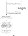
- an embodiment of the present invention provides a D2D data transmission method. As shown in FIG. 2 , the method includes the following steps.
- UE 2 sends a first message to n UEs 1, where the first message is used to indicate that the UE 2 needs to transmit data to a base station.
- Each of the n UEs 1 separately receives the first message.
- Each of the n UEs 1 separately sends a second message to the UE 2, where the second message includes a user identity of the UE 1 and/or status information of the UE 1.
- the status information of the UE 1 is specifically information used to reflect a status of the UE 1.
- the status information includes at least one or any combination of the following information: current memory usage, current power supply usage or remaining power, a processing capability of a central processing unit (English: Central Processing Unit, CPU for short), a link status between the UE and the base station, or interference.
- the status information may be any information or may be a combination of any information in the information such as the current memory usage, the current power supply usage or remaining power, the processing capability of the central processing unit CPU, the link status between the UE and the base station, or the interference.
- first information is the current memory usage, and the current power supply usage or remaining power; or first information is the link status between the UE and the base station, and the interference. This is not specifically limited in this embodiment of the present invention.
- the current memory usage generally refers to a current memory usage ratio or a current memory remaining ratio.
- the current memory usage is the current memory usage ratio 60%.
- the current power supply usage generally refers to a current power supply used ratio.
- the current power supply usage is a current power supply used ratio 20%.
- the current power supply remaining power generally refers to a current power supply remaining power ratio. For example, the current power supply remaining power is 20%.
- the processing capability of the CPU means that in a unit of time, a capability of processing information by the CPU may be reflected by a speed of running a program by the CPU.
- the link status between the UE and the base station includes a link stability status between the UE and the base station, interference between the UE and the base station, and the like.
- a specific link status may be reflected by a value of a downlink reference signal received power (English: Reference Signal Receiving Power, RSRP for short) or a downlink signal to interference plus noise ratio (English: Signal to Interference plus Noise Ratio, SINR for short).
- RSRP Reference Signal Receiving Power
- SINR Signal to Interference plus Noise Ratio
- the interference includes an interference or noise status of a link between the UE 2 and the UE 1.
- the UE 2 receives n second messages from the n UEs 1, where each UE 1 sends one second message to the UE 2.
- the UE 2 determines relay UE from the n UEs 1 according to the user identity of each UE 1 and/or the status information of each UE 1, where the relay UE is UE that transmits the data to the base station.
- that the UE 2 determines relay UE from the n UEs 1 according to the user identity of each UE 1 and/or the status information of each UE 1 may specifically include: The UE 2 determines the relay UE from the n UEs 1 according to the user identity of each UE 1 and/or the status information of each UE 1 and with reference to a preset policy.
- the preset policy may include: UE 1 that has a smallest current memory usage ratio is the relay UE; or
- the preset policy may be other content, and the foregoing provides merely examples for description. This is not specifically limited in this embodiment of the present invention.
- the UE 2 transmits the data to the base station by using the relay UE.
- the UE 2 After determining the relay UE, the UE 2 transmits the data to the base station by using the relay UE.
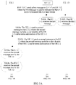
- the method includes the following steps.
- UE 2 sends a first message to UE 1-1 and UE 1-2, where the first message is used to indicate that the UE 2 needs to transmit data to a base station.
- the UE 1-1 receives the first message.
- the UE 1-1 sends a second message to the UE 2, where the second message includes a user identity of the UE 1-1 and/or status information of the UE 1-1.
- the UE 2 receives the second message sent by the UE 1-1.
- the UE 1-2 receives the first message.
- the UE 1-2 sends a second message to the UE 2, where the second message includes a user identity of the UE 1-2 and/or status information of the UE 1-2.
- the UE 2 receives the second message sent by the UE 1-2.
- steps S302a to 304a and steps S302b to 304b are not necessarily performed in a specific order. Steps S302a to 304a may be performed before steps S302b to 304b, or steps S302b to 304b may be performed before steps S302a to 304a, or steps S302a to 304a and steps S302b to 304b may be simultaneously performed. This is not specifically limited in this embodiment of the present invention.
- step S303a and step S303b refer to related description in step S203 in the embodiment shown in FIG. 2 . Details are not described herein.
- the UE 2 determines relay UE from the UE 1-1 and the UE 1-2 according to the user identity of the UE 1-1 and/or the status information of the UE 1- and the user identity of the UE 1-2 and/or the status information of the UE 2-, where the relay UE is UE that transmits the data to the base station.
- the UE 2 determines the relay UE from the UE 1-1 and the UE 1-2 according to the user identity of the UE 1-1 and/or the status information of the UE 1- and the user identity of the UE 1-2 and/or the status information of the UE 2-, refer to related description in step S205 in the embodiment shown in FIG. 2 . Details are not described herein.
- the UE 2 transmits the data to the base station by using the relay UE.
- n 2
- n 2
- n 2
- n 2
- n 2
- n 2
- a similar implementation may be obtained by analogy according to the example shown in FIG. 3A and FIG. 3B . Details are not described in this embodiment of the present invention.
- each of the n UEs 1 separately sends the second message to the UE 2.
- the second message includes the user identity of the UE 1 and/or the status information of the UE 1.
- the UE 2 may determine the relay UE from the n UEs 1 according to the user identity of each of the n UEs 1 and/or the status information of each of the n UEs 1, and further transmit the data to the base station by using the relay UE, where n is an integer not less than 2. That is, a solution below is provided: When there are usually a plurality of candidate UEs in network coverage, one suitable UE is found from the plurality of candidate UEs and used as relay UE, to transmit information from UE out of network coverage to a base station. Therefore, this resolves a problem about how to find UE in network coverage that can be used as relay UE to transmit information from UE out of network coverage to a base station.
- the base station may configure one resource pool for the UE 2 and each of the n UEs 1.
- the UE 2 may receive and send a message in the resource pool, and each of the n UEs 1 may receive and send a message in the resource pool. That is, in the embodiment shown in FIG. 2 , that UE 2 sends a first message to n UEs 1 (step S201) may specifically include:
- the UE 2 sends, in the resource pool preconfigured by the base station, the first message to the n UEs 1.
- each of the n UEs 1 separately receives the first message may specifically include: Each of the n UEs 1 separately receives the first message in the resource pool.
- each of the n UEs 1 separately sends a second message to the UE 2 may specifically include: Each of the n UEs 1 separately sends, in the resource pool, the second message to the UE 2.
- That the UE 2 receives n second messages from the n UEs 1 may specifically include: The UE 2 receives, in the resource pool, the n second messages from the n UEs 1.
- different resources in the resource pool preconfigured by the base station may be separately allocated to the UE 2 and the n UEs 1.
- the resource pool includes a first resource and a second resource
- the first resource is allocated to and used by the UE 2 to send the first message and receive the second message
- the second resource is allocated to and used by the n UEs 1 to send the second message and receive the first message.
- the first message may further include an indication that the n UEs 1 need to feed back information.
- each of the n UEs 1 separately sends a second message to the UE 2 may specifically include: Each of the n UEs 1 separately sends the second message to the UE 2 according to the indication that the n UEs 1 need to feed back information.
- the indication for feeding back information may be specifically that information that needs to be fed back by each of the n UEs 1 includes the status information. This is not specifically limited in this embodiment of the present invention.
- the first message further includes a preset threshold that the status information of the n UEs 1 needs to meet.
- the method may further include: Each of the n UEs 1 determines, according to the preset threshold that the status information of the n UEs 1 needs to meet, whether the status information of the UE 1 accords with the preset threshold.
- That each of the n UEs 1 separately sends a second message to the UE 2 may specifically include: If the status information of the UE 1 accords with the preset threshold, the UE 1 sends the second message to the UE 2.
- the UE 1 does not send the second message to the UE 2. This is not specifically limited in this embodiment of the present invention.
- the preset threshold may include: A current memory usage ratio is less than the preset threshold; or
- the preset threshold may be other content, and the foregoing merely provides several possible preset thresholds. This is not specifically limited in this embodiment of the present invention.
- the status information needs to meet the preset threshold herein specifically means that each piece of information in the status information needs to meet a respective preset threshold.
- the status information includes the current power supply remaining power and the current memory usage
- a preset threshold of the current power supply remaining power is greater than or equal to 50%
- a preset threshold of the current memory usage is less than or equal to 40%. If the current power supply remaining power of UE 1-1 is 70%, and the current memory usage is 50%, in this case, the current memory usage in the status information of the UE 1-1 does not meet the preset threshold, and the second message is not to be sent to the UE 2. If the current power supply remaining power of UE 1-3 is 70%, and the current memory usage is 20%, in this case, the status information of the UE 1-3 accords with the preset threshold, and the second message is sent to the UE 2. Therefore, workload of selecting one suitable UE from a plurality of candidate UEs as relay UE by the UE 2 can be greatly reduced, so that power consumption of the UE 2 is reduced, and signaling overheads are reduced.
- an embodiment of the present invention further provides a D2D data transmission method.
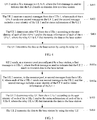
- UE 2 is used as an execution body for description. As shown in FIG. 4 , the method includes the following steps.
- the UE 2 sends a first message to n UEs 1, where the first message is used to indicate that the UE 2 needs to transmit data to a base station.
- the UE 2 receives n second messages from the n UEs 1, where each of the n UEs 1 sends one second message to the UE 2, and the second message includes a user identity of the UE 1 and/or status information of the UE 1.
- step S203 in the embodiment shown in FIG. 2 . Details are not described in this embodiment of the present invention.
- the UE 2 determines relay UE from the n UEs 1 according to the user identity of each of the n UEs 1 and/or the status information of each of the n UEs 1, where the relay UE is UE that transmits the data to the base station.
- step S403 refers to related description in step S205 in the embodiment shown in FIG. 2 . Details are not described in this embodiment of the present invention.
- the UE 2 transmits the data to the base station by using the relay UE.
- the base station may pre-configure a resource pool, and the UE 2 may receive and send a message in the resource pool. That is, as shown in FIG. 5 , that the UE 2 sends a first message to n UEs 1 (step S401) may specifically include: S401a. The UE 2 sends, in the resource pool preconfigured by the base station, the first message to the n UEs 1.
- That the UE 2 receives n second messages from the n UEs 1 may specifically include: S402a.
- the UE 2 receives, in the resource pool, the n second messages from the n UEs 1.
- different resources in the resource pool preconfigured by the base station may be separately allocated to the UE 2 and the n UEs 1.
- the resource pool preconfigured by the base station includes a first resource and a second resource
- the first resource is allocated to and used by the UE 2 to send the first message and receive the second message
- the second resource is allocated to and used by the n UEs 1 to send the second message and receive the first message.
- the first message may further include an indication that the n UEs 1 need to feed back information.
- the indication for feeding back information may be specifically that information that needs to be fed back by each of the n UEs 1 includes the status information.
- the indication for feeding back information may be specifically that information that needs to be fed back by each of the n UEs 1 includes the status information.
- the first message further includes a preset threshold that the status information of the n UEs 1 needs to meet.
- the UE 2 receives the n second messages from the n UEs 1.
- Each of the n UEs 1 sends one second message to the UE 2, and the second message includes the user identity of the UE 1 and/or the status information of the UE 1.
- the UE 2 may determine the relay UE from the n UEs 1 according to the user identity of each of the n UEs 1 and/or the status information of each of the n UEs 1, and further transmit the data to the base station by using the relay UE, where n is an integer not less than 2. That is, a solution below is provided: When there are usually a plurality of candidate UEs in network coverage, one suitable UE is found from the plurality of candidate UEs and used as relay UE, to transmit information from UE out of network coverage to a base station. Therefore, this resolves a problem about how to find UE in network coverage that can be used as relay UE to transmit information from UE out of network coverage to a base station.
- an embodiment of the present invention further provides a D2D data transmission method.
- UE 1-x (it is assumed that the UE 1-x is any UE in n UEs 1) is used as an execution body for description. As shown in FIG. 6 , the method includes the following steps.
- the UE 1-x receives a first message sent by UE 2, where the first message is used to indicate that the UE 2 needs to transmit data to a base station.
- the UE 1-x sends a second message to the UE 2, where the second message includes a user identity of the UE 1-x and/or status information of the UE 1-x.
- step S203 in the embodiment shown in FIG. 2 . Details are not described in this embodiment of the present invention.
- the UE 1-x When the UE 1-x is determined as relay UE by the UE 2 according to the user identity of the UE 1-x and/or the status information of the UE 1-x, the UE 1-x receives the data sent by the UE 2 and transmits the data to the base station, where the relay UE is UE that transmits the data to the base station.
- the UE 2 determines the UE 1-x as the relay UE according to the user identity of the UE 1-x and/or the status information of the UE 1-x, refer to description in the foregoing interaction embodiments. Details are not described herein.
- the base station may pre-configure a resource pool, and the UE 1-x may receive and send a message in the resource pool. That is, as shown in FIG. 7 , that the UE 1-x receives a first message sent by UE 2 (step S601) may specifically include: S601a.
- the UE 1-x receives, in the resource pool preconfigured by the base station, the first message sent by the UE 2.
- That the UE 1-x sends a second message to the UE 2 may specifically include: S602a.
- the UE 1-x sends, in the resource pool, the second message to the UE 2.
- different resources in the resource pool preconfigured by the base station may be separately allocated to the UE 2 and the UE 1-x.
- the resource pool preconfigured by the base station includes a first resource and a second resource
- the first resource is allocated to and used by the UE 2 to send the first message and receive the second message separately sent by each of the n UEs 1
- the second resource is allocated to and used by the n UEs 1 (including the UE 1-x) to send the second message and receive the first message.
- the first message may further include an indication that the n UEs 1 need to feed back information.
- the UE 1-x sends a second message to the UE 2 may specifically include: The UE 1-x sends the second message to the UE 2 according to the indication that the n UEs 1 need to feed back information.
- the indication for feeding back information may be specifically that information that needs to be fed back by each of the n UEs 1 includes the status information. This is not specifically limited in this embodiment of the present invention.
- the first message further includes a preset threshold that the status information of the n UEs 1 needs to meet.
- the method may further include: The UE 1-x determines, according to the preset threshold that the status information of the n UEs 1 needs to meet, whether the status information of the UE 1-x accords with the preset threshold.
- That the UE 1-x sends a second message to the UE 2 may specifically include: If the status information of the UE 1-x accords with the preset threshold, the UE 1-x sends the second message to the UE 2.
- the UE 1-x does not send the second message to the UE 2. This is not specifically limited in this embodiment of the present invention.
- the UE 1-x (any UE in n candidate UEs in the network coverage area of the base station) receives the first message sent by the UE 2 (UE out of the network coverage area of the base station)
- the UE 1-x sends the second message to the UE 2.
- the second message includes the user identity of the UE 1-x and/or the status information of the UE 1-x.
- the UE 2 may determine the relay UE from the n UEs 1 according to the user identity of each of the n UEs 1 and/or the status information of each of the n UEs 1, and further transmit the data to the base station by using the relay UE, where n is an integer not less than 2. That is, a solution below is provided: When there are usually a plurality of candidate UEs in network coverage, one suitable UE is found from the plurality of candidate UEs and used as relay UE, to transmit information from UE out of network coverage to a base station.
- An embodiment of the present invention further provides source UE 80.
- the source UE 80 includes a sending unit 801, a receiving unit 802, and a processing unit 803.
- the sending unit 801 is configured to send a first message to n candidate UEs, where the first message is used to indicate that the source UE 80 needs to transmit data to a base station, the source UE 80 is UE out of a network coverage area of the base station, the n candidate UEs are UEs in the network coverage area of the base station, and n is an integer not less than 2.
- the receiving unit 802 is configured to receive n second messages from the n candidate UEs, where each of the n candidate UEs sends one second message to the source UE 80, and the second message includes a user identity of each candidate UE and/or status information of each candidate UE.
- the processing unit 803 is configured to determine relay UE from the n candidate UEs according to the user identity of each candidate UE and/or the status information of each candidate UE, where the relay UE is UE that transmits the data to the base station.
- the sending unit 801 is further configured to transmit the data to the base station by using the relay UE.
- the sending unit 801 is specifically configured to: send, in a resource pool preconfigured by the base station, the first message to the n candidate UEs.
- the receiving unit 802 is specifically configured to: receive, in the resource pool, the n second messages from the n candidate UEs.
- the resource pool includes a first resource and a second resource
- the first resource is allocated to and used by the source UE 80 to send the first message and receive the second message
- the second resource is allocated to and used by the n candidate UEs to send the second message and receive the first message.
- the status information includes at least one or any combination of the following information: current memory usage, current power supply usage or remaining power, a processing capability of a central processing unit CPU, a link status between the UE and the base station, or interference.
- the first message includes an indication that the n candidate UEs need to feed back information.
- the first message includes a preset threshold that the status information of the n candidate UEs needs to meet.
- the sending unit 801 in this embodiment may be an interface circuit that has a transmit function and that is on the source UE 80, for example, a transmitter.
- the receiving unit 802 may be an interface circuit that has a reception function and that is on the source UE 80, for example, a receiver.
- the processing unit 803 may be a processor disposed independently, or may be integrated into a processor of the source UE 80.
- the processing unit 803 may be stored in a memory of the source UE 80 in a form of program code, and a processor of the source UE 80 calls and performs a function of the processing unit 803.
- the processor herein may be a central processing unit (English: Central Processing Unit, CPU for short) or an application-specific integrated circuit (English: Application Specific Integrated Circuit, ASIC for short), or one or more integrated circuits configured to implement this embodiment of the present invention.
- This embodiment of the present invention provides the source UE, and the source UE is UE out of the network coverage area of the base station. After the source UE sends the first message to the n candidate UEs in the network coverage area of the base station, the source UE receives the n second messages from the n candidate UEs. Each of the n candidate UEs sends one second message to the source UE, and the second message includes the user identity of each candidate UE and/or the status information of each candidate UE.
- the source UE may determine the relay UE from the n candidate UEs according to the user identity of each candidate UE and/or the status information of each candidate UE, and further transmit the data to the base station by using the relay UE, where n is an integer not less than 2. That is, according to the source UE provided in this embodiment of the present invention, when there are a plurality of candidate UEs in network coverage, one suitable UE may be found from the plurality of candidate UEs and used as relay UE, to transmit information from UE out of network coverage to a base station. Therefore, this resolves a problem about how to find UE in network coverage that can be used as relay UE to transmit information from UE out of network coverage to a base station.
- An embodiment of the present invention provides candidate UE 90.
- the candidate UE 90 includes a receiving unit 901 and a sending unit 902.
- the receiving unit 901 is configured to receive a first message sent by source UE, where the first message is used to indicate that the source UE needs to transmit data to a base station, the source UE is UE out of a network coverage area of the base station, the candidate UE 90 is UE in n candidate UEs 90 in the network coverage area of the base station, and n is an integer not less than 2.
- the sending unit 902 is configured to send a second message to the source UE, where the second message includes a user identity of the candidate UE 90 and/or status information of the candidate UE 90.
- the receiving unit 901 is further configured to: when the candidate UE 90 is determined as relay UE by the source UE according to the user identity of the candidate UE 90 and/or the status information of the candidate UE 90, receive the data sent by the source UE, where the relay UE is UE that transmits the data to the base station.
- the sending unit 902 is further configured to transmit the data to the base station. Further, the receiving unit 901 is specifically configured to: receive, in a resource pool preconfigured by the base station, the first message sent by the source UE.
- the sending unit 902 is specifically configured to: send, in the resource pool, the second message to the source UE.
- the resource pool includes a first resource and a second resource
- the first resource is allocated to and used by the source UE to send the first message and receive the second message
- the second resource is allocated to and used by the n candidate UEs 90 to send the second message and receive the first message.
- the status information includes at least one or any combination of the following information: current memory usage, current power supply usage or remaining power, a processing capability of a central processing unit CPU, a link status between the UE and the base station, or interference.
- the first message includes an indication that the n candidate UEs 90 need to feed back information.
- the first message includes a preset threshold that status information of the n candidate UEs 90 needs to meet.
- the sending unit 902 in this embodiment may be an interface circuit that has a transmit function and that is on the candidate UE 90, for example, a transmitter.
- the receiving unit 901 may be an interface circuit that has a reception function and that is on the candidate UE 90, for example, a receiver.
- This embodiment of the present invention provides the candidate UE, and the candidate UE is UE in the n candidate UEs in the network coverage area of the base station.
- the candidate UE After receiving the first message sent by the source UE, the candidate UE sends the second message to the source UE.
- the second message includes the user identity of the candidate UE and/or the status information of the candidate UE.
- the source UE may determine the relay UE from the n candidate UEs according to the user identity of each candidate UE and/or the status information of each candidate UE, and further transmit the data to the base station by using the relay UE, where n is an integer not less than 2.
- the candidate UE when there are a plurality of candidate UEs in network coverage, one suitable UE may be found from the plurality of candidate UEs and used as relay UE, to transmit information from UE out of network coverage to a base station. Therefore, this resolves a problem about how to find UE in network coverage that can be used as relay UE to transmit information from UE out of network coverage to a base station.
- An embodiment of the present invention further provides source UE 100.
- the source UE 100 includes a processor 1001, a first interface circuit 1002a, a second interface circuit 1002b, a memory 1003, and a bus 1004, and the processor 1001, the first interface circuit 1002a, the second interface circuit 1002b, and the memory 1003 are connected and complete mutual communication by using the bus 1004.
- the processor 1001 herein may be one processor 1001, or may be a general term of a plurality of processing elements.
- the processor 1001 may be a CPU, or may be an ASIC, or one or more integrated circuits configured to implement this embodiment of the present invention, such as one or more microprocessors 1001 (English: digital singnal processor, DSP for short), or one or more field programmable gate arrays (English: Field Programmable Gate Array, FPGA for short).
- the memory 1003 may be one storage apparatus or may be a general term of a plurality of storage elements, and is configured to store executable program code or a parameter, data, and the like that are required for running an access network management device.
- the memory 1003 may include a random access memory (English: Random-Access Memory, RAM for short), or may include a non-volatile memory (English: non-volatile memory, NVRAM for short), such as a magnetic disk memory or a flash memory (Flash).
- the bus 1004 may be an industry standard architecture (English: Industry Standard Architecture, ISA for short) bus, a Peripheral Component Interconnect (English: Peripheral Component, PCI for short) bus, an extended industry standard architecture (English: Extended Industry Standard Architecture, EISA for short) bus, or the like.
- the bus 1004 may be classified into an address bus, a data bus, a control bus, and the like. For ease of denotation, the bus 1004 is indicated by using only one bold line in FIG. 10 ; however, it does not indicate that there is only one bus or only one type of bus.
- the first interface circuit 1002a is configured to send a first message to n candidate UEs, where the first message is used to indicate that the source UE 100 needs to transmit data to a base station, the source UE 100 is UE out of a network coverage area of the base station, the n candidate UEs are UEs in the network coverage area of the base station, and n is an integer not less than 2.
- the second interface circuit 1002b is configured to receive n second messages from the n candidate UEs, where each of the n candidate UEs sends one second message to the source UE 100, and the second message includes a user identity of each candidate UE and/or status information of each candidate UE.
- the processor 1001 is configured to determine relay UE from the n candidate UEs according to the user identity of each candidate UE and/or the status information of each candidate UE, where the relay UE is UE that transmits the data to the base station.
- the first interface circuit 1002a is further configured to transmit the data to the base station by using the relay UE.
- the first interface circuit 1002a is specifically configured to: send, in a resource pool preconfigured by the base station, the first message to the n candidate UEs.
- the second interface circuit 1002b is specifically configured to: receive, in the resource pool, the n second messages from the n candidate UEs.
- the resource pool includes a first resource and a second resource
- the first resource is allocated to and used by the source UE 100 to send the first message and receive the second message
- the second resource is allocated to and used by the n candidate UEs to send the second message and receive the first message.
- the status information includes at least one or any combination of the following information: current memory usage, current power supply usage or remaining power, a processing capability of a central processing unit CPU 1001, a link status between the UE and the base station, or interference.
- the first message includes an indication that the n candidate UEs need to feed back information.
- the first message includes a preset threshold that the status information of the n candidate UEs needs to meet.
- This embodiment of the present invention provides the source UE, and the source UE is UE out of the network coverage area of the base station. After the source UE sends the first message to the n candidate UEs in the network coverage area of the base station, the source UE receives the n second messages from the n candidate UEs. Each of the n candidate UEs sends one second message to the source UE, and the second message includes the user identity of each candidate UE and/or the status information of each candidate UE.
- the source UE may determine the relay UE from the n candidate UEs according to the user identity of each candidate UE and/or the status information of each candidate UE, and further transmit the data to the base station by using the relay UE, where n is an integer not less than 2. That is, according to the source UE provided in this embodiment of the present invention, when there are a plurality of candidate UEs in network coverage, one suitable UE may be found from the plurality of candidate UEs and used as relay UE, to transmit information from UE out of network coverage to a base station. Therefore, this resolves a problem about how to find UE in network coverage that can be used as relay UE to transmit information from UE out of network coverage to a base station.
- An embodiment of the present invention further provides candidate UE 110.
- the candidate UE 110 includes a first interface circuit 1101a, a second interface circuit 1101b, a memory 1102, and a bus 1103, and the first interface circuit 1101a, the second interface circuit 1101b, and the memory 1102 are connected and complete mutual communication by using the bus 1103.
- the memory 1102 herein may be one storage apparatus, or may be a general term of a plurality of storage elements, and is configured to store executable program code or a parameter, data, and the like that are required for running an access network management device.
- the memory 1102 may include a RAM or an NVRAM, for example, a magnetic disk memory or a flash memory (Flash).
- the bus 1103 may be an ISA bus, a PCI bus, an EISA bus, or the like.
- the bus 1103 may be classified into an address bus, a data bus, a control bus, and the like.
- the bus 1103 is indicated by using only one bold line in FIG. 11 ; however, it does not indicate that there is only one bus or only one type of bus.
- the first interface circuit 1101a is configured to receive a first message sent by source UE, where the first message is used to indicate that the source UE needs to transmit data to a base station, the source UE is UE out of a network coverage area of the base station, the candidate UE 110 is UE in n candidate UEs 110 in the network coverage area of the base station, and n is an integer not less than 2.
- the second interface circuit 1101b is configured to send a second message to the source UE, where the second message includes a user identity of the candidate UE 110 and/or status information of the candidate UE 110.
- the first interface circuit 1101a is further configured to: when the candidate UE 110 is determined as relay UE by the source UE according to the user identity of the candidate UE 110 and/or the status information of the candidate UE 110, receive the data sent by the source UE, where the relay UE is UE that transmits the data to the base station.
- the second interface circuit 1101b is further configured to transmit the data to the base station.
- the first interface circuit 1101a is specifically configured to: receive, in a resource pool preconfigured by the base station, the first message sent by the source UE.
- the second interface circuit 1101b is specifically configured to: send, in the resource pool, the second message to the source UE.
- the resource pool includes a first resource and a second resource
- the first resource is allocated to and used by the source UE to send the first message and receive the second message
- the second resource is allocated to and used by the n candidate UEs 110 to send the second message and receive the first message.
- the status information includes at least one or any combination of the following information: current memory usage, current power supply usage or remaining power, a processing capability of a central processing unit CPU, a link status between the UE and the base station, or interference.
- the first message includes an indication that the n candidate UEs 110 need to feed back information.
- the first message includes a preset threshold that status information of the n candidate UEs 110 needs to meet.
- This embodiment of the present invention provides the candidate UE, and the candidate UE is UE in the n candidate UEs in the network coverage area of the base station.
- the candidate UE After receiving the first message sent by the source UE, the candidate UE sends the second message to the source UE.
- the second message includes the user identity of the candidate UE and/or the status information of the candidate UE.
- the source UE may determine the relay UE from the n candidate UEs according to the user identity of each candidate UE and/or the status information of each candidate UE, and further transmit the data to the base station by using the relay UE, where n is an integer not less than 2.
- the candidate UE when there are a plurality of candidate UEs in network coverage, one suitable UE may be found from the plurality of candidate UEs and used as relay UE, to transmit information from UE out of network coverage to a base station. Therefore, this resolves a problem about how to find UE in network coverage that can be used as relay UE to transmit information from UE out of network coverage to a base station.
- a computer readable medium (or media) is further provided, including a computer readable instruction that performs the following operation when the instruction is executed: performing the operations in the method embodiments shown in FIG. 2 to FIG. 7 in the foregoing embodiments.
- a computer program product including the foregoing computer readable medium.
- sequence numbers of the foregoing processes do not mean execution sequences in various embodiments of the present invention.
- the execution sequences of the processes should be determined according to functions and internal logic of the processes, and should not be construed as any limitation on the implementation processes of the embodiments of the present invention.
- the disclosed system, apparatus, and method may be implemented in other manners.
- the described apparatus embodiment is merely an example.
- the module or unit division is merely logical function division and may be other division in actual implementation.
- a plurality of units or components may be combined or integrated into another system, or some features may be ignored or not performed.
- the displayed or discussed mutual couplings or direct couplings or communication connections may be implemented by using some interfaces.
- the indirect couplings or communication connections between the apparatuses or units may be implemented in electronic, mechanical, or other forms.
- the units described as separate parts may or may not be physically separate, and parts displayed as units may or may not be physical units, may be located in one position, or may be distributed on a plurality of network units. Some or all of the units may be selected according to actual requirements to achieve the objectives of the solutions of the embodiments.
- functional units in the embodiments of the present invention may be integrated into one processing unit, or each of the units may exist alone physically, or two or more units are integrated into one unit.
- the integrated unit may be implemented in a form of hardware, or may be implemented in a form of a software functional unit.
- the integrated unit When the integrated unit is implemented in the form of a software functional unit and sold or used as an independent product, the integrated unit may be stored in a computer-readable storage medium. Based on such an understanding, the technical solutions of the present invention essentially, or the part contributing to the prior art, or all or a part of the technical solutions may be implemented in the form of a software product.
- the software product is stored in a storage medium and includes several instructions for instructing a computer device (which may be a personal computer, a server, or a network device) or a processor to perform all or a part of the steps of the methods described in the embodiments of the present invention.
- the foregoing storage medium includes: any medium that can store program code, such as a USB flash drive, a removable hard disk, a read-only memory (ROM, Read-Only Memory), a random access memory (RAM, Random Access Memory), a magnetic disk, or an optical disc.
- program code such as a USB flash drive, a removable hard disk, a read-only memory (ROM, Read-Only Memory), a random access memory (RAM, Random Access Memory), a magnetic disk, or an optical disc.
Landscapes
- Engineering & Computer Science (AREA)
- Computer Networks & Wireless Communication (AREA)
- Signal Processing (AREA)
- Databases & Information Systems (AREA)
- Computer Security & Cryptography (AREA)
- Mobile Radio Communication Systems (AREA)
Applications Claiming Priority (1)
| Application Number | Priority Date | Filing Date | Title |
|---|---|---|---|
| PCT/CN2015/089439 WO2017041293A1 (fr) | 2015-09-11 | 2015-09-11 | Procédé, dispositif et système de transmission de données de dispositif à dispositif (d2d) |
Publications (3)
| Publication Number | Publication Date |
|---|---|
| EP3322221A1 true EP3322221A1 (fr) | 2018-05-16 |
| EP3322221A4 EP3322221A4 (fr) | 2018-08-15 |
| EP3322221B1 EP3322221B1 (fr) | 2021-04-07 |
Family
ID=58240511
Family Applications (1)
| Application Number | Title | Priority Date | Filing Date |
|---|---|---|---|
| EP15903399.2A Active EP3322221B1 (fr) | 2015-09-11 | 2015-09-11 | Procédé, dispositif et système de transmission de données de dispositif à dispositif (d2d) |
Country Status (4)
| Country | Link |
|---|---|
| US (1) | US10609743B2 (fr) |
| EP (1) | EP3322221B1 (fr) |
| CN (1) | CN107836125A (fr) |
| WO (1) | WO2017041293A1 (fr) |
Families Citing this family (3)
| Publication number | Priority date | Publication date | Assignee | Title |
|---|---|---|---|---|
| US10667314B2 (en) * | 2017-03-30 | 2020-05-26 | Lg Electronics Inc. | Method and apparatus for transmitting and receiving a signal in a wireless communication system supporting a relay UE |
| CN111491287A (zh) * | 2019-01-25 | 2020-08-04 | 电信科学技术研究院有限公司 | 一种调度终端确定方法、终端和网络侧设备 |
| WO2022147695A1 (fr) * | 2021-01-06 | 2022-07-14 | 北京小米移动软件有限公司 | Procédé et appareil de sélection d'ue relais, procédé et appareil de traitement d'informations, dispositif et support |
Family Cites Families (24)
| Publication number | Priority date | Publication date | Assignee | Title |
|---|---|---|---|---|
| US7853204B2 (en) * | 2004-10-21 | 2010-12-14 | Panasonic Corporation | Method and system for identifying a relay mobile station in a wireless communication network |
| US8826348B2 (en) * | 2006-12-04 | 2014-09-02 | Samsung Electronics Co., Ltd. | System and method for wireless communication of uncompressed video having a relay device for power saving |
| US7995507B2 (en) * | 2006-12-04 | 2011-08-09 | Samsung Electronics Co., Ltd. | System and method for wireless communication of uncompressed video having power saving capability |
| US9014062B2 (en) * | 2010-12-27 | 2015-04-21 | Electronics And Telecommunications Research Institute | Method for HARQ and link adaptation of device to device link in direct communication between user equipments and relaying by user equipment |
| US20130294331A1 (en) * | 2012-05-03 | 2013-11-07 | Mediatek Singapore Pte. Ltd. | Method for Distributed Relay Discovery and Data Forwarding |
| KR101924838B1 (ko) * | 2012-08-10 | 2018-12-05 | 삼성전자주식회사 | 무선 통신 네트워크에서 2 홉 링크 전송을 위한 방법 및 장치 |
| US9072000B2 (en) * | 2012-10-19 | 2015-06-30 | Qualcomm Incorporated | Power efficient relay discovery protocol |
| CN104105155B (zh) | 2013-04-01 | 2019-07-16 | 中兴通讯股份有限公司 | 接收设备发现信息、发送设备发现信息的方法和用户设备 |
| EP2790456B1 (fr) | 2013-04-10 | 2015-10-21 | Fujitsu Limited | Communication D2D dans des réseaux sans fil |
| EP2833694A3 (fr) * | 2013-07-29 | 2015-04-01 | HTC Corporation | Procédé de découverte de relais et communication dans un système de communication sans fil |
| US9445352B2 (en) * | 2013-07-30 | 2016-09-13 | Qualcomm Incorporated | Power efficient discovery of LTE-direct relay for out-of-coverage devices |
| US9532361B2 (en) * | 2013-08-09 | 2016-12-27 | Futurewei Technologies, Inc. | System and method for resource allocation device-to-device for open discovery |
| CN103607750A (zh) | 2013-11-25 | 2014-02-26 | 南京邮电大学 | 下一代蜂窝系统中基于终端直通通信的中继选择方法 |
| US9906888B2 (en) * | 2013-12-16 | 2018-02-27 | Qualcomm Incorporated | Hybrid relay scheme |
| EP3103306B1 (fr) * | 2014-02-04 | 2019-10-23 | Telefonaktiebolaget LM Ericsson (publ) | Procédés, dispositif sans fil, station de base et station relais candidate pour supporter la communication d2d sur relais |
| KR20150094325A (ko) * | 2014-02-11 | 2015-08-19 | 삼성전자주식회사 | UE-relay 동작에 있어 power saving을 위한 통신 방법 |
| US10660146B2 (en) * | 2014-03-21 | 2020-05-19 | Samsung Electronics Co., Ltd. | Methods and apparatus for device to device synchronization priority |
| CN103974288B (zh) | 2014-05-23 | 2017-06-06 | 电子科技大学 | 蜂窝网中d2d资源分配方法 |
| CN104540236B (zh) * | 2015-01-30 | 2017-04-05 | 深圳酷派技术有限公司 | 用于终端直连通信的资源配置方法、系统、终端和基站 |
| US10057352B2 (en) * | 2015-03-13 | 2018-08-21 | Qualcomm Incorporated | Internet of everything device relay discovery and selection |
| US10530461B2 (en) | 2015-03-25 | 2020-01-07 | Qualcomm Incorporated | Relay discovery and association messages |
| CN106465225A (zh) * | 2015-04-03 | 2017-02-22 | 华为技术有限公司 | 数据传输的方法、用户设备和基站 |
| CN104703224B (zh) | 2015-04-09 | 2018-05-15 | 宇龙计算机通信科技(深圳)有限公司 | 用于d2d通信的资源配置方法、装置和终端 |
| EP3338492A4 (fr) * | 2015-08-21 | 2019-03-20 | Nokia Technologies Oy | Appareil, procédé et produit-programme d'ordinateur destinés à la commande d'accès au support dans un réseau de capteurs sans fil |
-
2015
- 2015-09-11 EP EP15903399.2A patent/EP3322221B1/fr active Active
- 2015-09-11 CN CN201580081487.3A patent/CN107836125A/zh active Pending
- 2015-09-11 US US15/758,613 patent/US10609743B2/en active Active
- 2015-09-11 WO PCT/CN2015/089439 patent/WO2017041293A1/fr not_active Ceased
Also Published As
| Publication number | Publication date |
|---|---|
| WO2017041293A1 (fr) | 2017-03-16 |
| US10609743B2 (en) | 2020-03-31 |
| EP3322221B1 (fr) | 2021-04-07 |
| CN107836125A (zh) | 2018-03-23 |
| US20180249520A1 (en) | 2018-08-30 |
| EP3322221A4 (fr) | 2018-08-15 |
Similar Documents
| Publication | Publication Date | Title |
|---|---|---|
| US9432818B2 (en) | Controlling communication devices | |
| KR102061436B1 (ko) | 자원 할당 방법과 기기 | |
| US12219655B2 (en) | Transmission method and apparatus of discovery signal and communication system | |
| US20180199312A1 (en) | Sidelink Information Transmission Device and Method and Communications System | |
| US10624115B2 (en) | Radio resource scheduling method, device and system | |
| US10548125B2 (en) | D2D resource allocation method, device, and system | |
| EP3751786A1 (fr) | Procédé destiné à acquérir des informations de tranche, et dispositif de relais | |
| KR102535608B1 (ko) | 전력 제어 방법 및 장치 | |
| WO2021134477A1 (fr) | Procédé d'apprentissage de faisceau et dispositif associé | |
| US11019629B2 (en) | Device-to-device communication method and apparatus | |
| EP3815442B1 (fr) | Indication de préemption multi-niveau de communications ultra-fiable et à faible latence | |
| WO2021083815A1 (fr) | Procédé et appareil de commutation de transmission de données entre des technologies d'accès radio pour une transmission de données précoce | |
| EP4199551A1 (fr) | Procédé de commande d'informations, appareil, et station de base | |
| EP4278833A1 (fr) | Dispositif terminal et procédé associé pour la réservation de ressources | |
| KR20230088910A (ko) | 정보 전송 처리 방법, 장치 및 단말 | |
| EP3322221A1 (fr) | Procédé, dispositif et système de transmission de données de dispositif à dispositif (d2d) | |
| EP3833146A1 (fr) | Procédé et appareil de transmission d'informations de commande de liaison descendante | |
| EP4515941B1 (fr) | Procédés pour un rapport de mesure l1 apériodique initié par un ue pour des cellules détectées sur la base de mesures l3 | |
| EP2999285B1 (fr) | Procédé de transmission de signal dans un service de proximité de dispositif à dispositif, station de base et équipement utilisateur | |
| US20220053524A1 (en) | Resource scheduling method and apparatus | |
| JP6997200B2 (ja) | 端末、端末の通信方法、及び基地局装置 | |
| JP7392844B2 (ja) | 車両通信サービスの通信方法、装置及び通信システム | |
| WO2020052763A1 (fr) | Transmission sans autorisation de liaison montante dans un réseau de communication | |
| KR102014758B1 (ko) | 탐색 정보 송신 방법, 디바이스, 및 통신 시스템 | |
| CN103841588A (zh) | 无线通信方法、设备及系统 |
Legal Events
| Date | Code | Title | Description |
|---|---|---|---|
| STAA | Information on the status of an ep patent application or granted ep patent |
Free format text: STATUS: THE INTERNATIONAL PUBLICATION HAS BEEN MADE |
|
| PUAI | Public reference made under article 153(3) epc to a published international application that has entered the european phase |
Free format text: ORIGINAL CODE: 0009012 |
|
| STAA | Information on the status of an ep patent application or granted ep patent |
Free format text: STATUS: REQUEST FOR EXAMINATION WAS MADE |
|
| 17P | Request for examination filed |
Effective date: 20180206 |
|
| AK | Designated contracting states |
Kind code of ref document: A1 Designated state(s): AL AT BE BG CH CY CZ DE DK EE ES FI FR GB GR HR HU IE IS IT LI LT LU LV MC MK MT NL NO PL PT RO RS SE SI SK SM TR |
|
| AX | Request for extension of the european patent |
Extension state: BA ME |
|
| A4 | Supplementary search report drawn up and despatched |
Effective date: 20180717 |
|
| RIC1 | Information provided on ipc code assigned before grant |
Ipc: H04W 40/22 20090101AFI20180711BHEP Ipc: H04W 8/00 20090101ALI20180711BHEP Ipc: H04W 40/00 20090101ALI20180711BHEP |
|
| DAV | Request for validation of the european patent (deleted) | ||
| DAX | Request for extension of the european patent (deleted) | ||
| STAA | Information on the status of an ep patent application or granted ep patent |
Free format text: STATUS: EXAMINATION IS IN PROGRESS |
|
| 17Q | First examination report despatched |
Effective date: 20190417 |
|
| REG | Reference to a national code |
Ref country code: DE Ref legal event code: R079 Ref document number: 602015067970 Country of ref document: DE Free format text: PREVIOUS MAIN CLASS: H04W0040220000 Ipc: H04W0088040000 |
|
| RIC1 | Information provided on ipc code assigned before grant |
Ipc: H04W 76/14 20180101ALI20200928BHEP Ipc: H04W 48/20 20090101ALI20200928BHEP Ipc: H04W 88/04 20090101AFI20200928BHEP |
|
| GRAP | Despatch of communication of intention to grant a patent |
Free format text: ORIGINAL CODE: EPIDOSNIGR1 |
|
| STAA | Information on the status of an ep patent application or granted ep patent |
Free format text: STATUS: GRANT OF PATENT IS INTENDED |
|
| INTG | Intention to grant announced |
Effective date: 20201106 |
|
| GRAS | Grant fee paid |
Free format text: ORIGINAL CODE: EPIDOSNIGR3 |
|
| GRAA | (expected) grant |
Free format text: ORIGINAL CODE: 0009210 |
|
| STAA | Information on the status of an ep patent application or granted ep patent |
Free format text: STATUS: THE PATENT HAS BEEN GRANTED |
|
| AK | Designated contracting states |
Kind code of ref document: B1 Designated state(s): AL AT BE BG CH CY CZ DE DK EE ES FI FR GB GR HR HU IE IS IT LI LT LU LV MC MK MT NL NO PL PT RO RS SE SI SK SM TR |
|
| REG | Reference to a national code |
Ref country code: GB Ref legal event code: FG4D |
|
| REG | Reference to a national code |
Ref country code: AT Ref legal event code: REF Ref document number: 1381360 Country of ref document: AT Kind code of ref document: T Effective date: 20210415 Ref country code: CH Ref legal event code: EP |
|
| REG | Reference to a national code |
Ref country code: DE Ref legal event code: R096 Ref document number: 602015067970 Country of ref document: DE |
|
| REG | Reference to a national code |
Ref country code: IE Ref legal event code: FG4D |
|
| REG | Reference to a national code |
Ref country code: LT Ref legal event code: MG9D |
|
| REG | Reference to a national code |
Ref country code: NL Ref legal event code: MP Effective date: 20210407 Ref country code: AT Ref legal event code: MK05 Ref document number: 1381360 Country of ref document: AT Kind code of ref document: T Effective date: 20210407 |
|
| PG25 | Lapsed in a contracting state [announced via postgrant information from national office to epo] |
Ref country code: HR Free format text: LAPSE BECAUSE OF FAILURE TO SUBMIT A TRANSLATION OF THE DESCRIPTION OR TO PAY THE FEE WITHIN THE PRESCRIBED TIME-LIMIT Effective date: 20210407 Ref country code: BG Free format text: LAPSE BECAUSE OF FAILURE TO SUBMIT A TRANSLATION OF THE DESCRIPTION OR TO PAY THE FEE WITHIN THE PRESCRIBED TIME-LIMIT Effective date: 20210707 Ref country code: AT Free format text: LAPSE BECAUSE OF FAILURE TO SUBMIT A TRANSLATION OF THE DESCRIPTION OR TO PAY THE FEE WITHIN THE PRESCRIBED TIME-LIMIT Effective date: 20210407 Ref country code: NL Free format text: LAPSE BECAUSE OF FAILURE TO SUBMIT A TRANSLATION OF THE DESCRIPTION OR TO PAY THE FEE WITHIN THE PRESCRIBED TIME-LIMIT Effective date: 20210407 Ref country code: LT Free format text: LAPSE BECAUSE OF FAILURE TO SUBMIT A TRANSLATION OF THE DESCRIPTION OR TO PAY THE FEE WITHIN THE PRESCRIBED TIME-LIMIT Effective date: 20210407 Ref country code: FI Free format text: LAPSE BECAUSE OF FAILURE TO SUBMIT A TRANSLATION OF THE DESCRIPTION OR TO PAY THE FEE WITHIN THE PRESCRIBED TIME-LIMIT Effective date: 20210407 |
|
| PG25 | Lapsed in a contracting state [announced via postgrant information from national office to epo] |
Ref country code: RS Free format text: LAPSE BECAUSE OF FAILURE TO SUBMIT A TRANSLATION OF THE DESCRIPTION OR TO PAY THE FEE WITHIN THE PRESCRIBED TIME-LIMIT Effective date: 20210407 Ref country code: SE Free format text: LAPSE BECAUSE OF FAILURE TO SUBMIT A TRANSLATION OF THE DESCRIPTION OR TO PAY THE FEE WITHIN THE PRESCRIBED TIME-LIMIT Effective date: 20210407 Ref country code: PT Free format text: LAPSE BECAUSE OF FAILURE TO SUBMIT A TRANSLATION OF THE DESCRIPTION OR TO PAY THE FEE WITHIN THE PRESCRIBED TIME-LIMIT Effective date: 20210809 Ref country code: PL Free format text: LAPSE BECAUSE OF FAILURE TO SUBMIT A TRANSLATION OF THE DESCRIPTION OR TO PAY THE FEE WITHIN THE PRESCRIBED TIME-LIMIT Effective date: 20210407 Ref country code: NO Free format text: LAPSE BECAUSE OF FAILURE TO SUBMIT A TRANSLATION OF THE DESCRIPTION OR TO PAY THE FEE WITHIN THE PRESCRIBED TIME-LIMIT Effective date: 20210707 Ref country code: IS Free format text: LAPSE BECAUSE OF FAILURE TO SUBMIT A TRANSLATION OF THE DESCRIPTION OR TO PAY THE FEE WITHIN THE PRESCRIBED TIME-LIMIT Effective date: 20210807 Ref country code: LV Free format text: LAPSE BECAUSE OF FAILURE TO SUBMIT A TRANSLATION OF THE DESCRIPTION OR TO PAY THE FEE WITHIN THE PRESCRIBED TIME-LIMIT Effective date: 20210407 Ref country code: GR Free format text: LAPSE BECAUSE OF FAILURE TO SUBMIT A TRANSLATION OF THE DESCRIPTION OR TO PAY THE FEE WITHIN THE PRESCRIBED TIME-LIMIT Effective date: 20210708 |
|
| REG | Reference to a national code |
Ref country code: DE Ref legal event code: R097 Ref document number: 602015067970 Country of ref document: DE |
|
| PG25 | Lapsed in a contracting state [announced via postgrant information from national office to epo] |
Ref country code: RO Free format text: LAPSE BECAUSE OF FAILURE TO SUBMIT A TRANSLATION OF THE DESCRIPTION OR TO PAY THE FEE WITHIN THE PRESCRIBED TIME-LIMIT Effective date: 20210407 Ref country code: ES Free format text: LAPSE BECAUSE OF FAILURE TO SUBMIT A TRANSLATION OF THE DESCRIPTION OR TO PAY THE FEE WITHIN THE PRESCRIBED TIME-LIMIT Effective date: 20210407 Ref country code: SM Free format text: LAPSE BECAUSE OF FAILURE TO SUBMIT A TRANSLATION OF THE DESCRIPTION OR TO PAY THE FEE WITHIN THE PRESCRIBED TIME-LIMIT Effective date: 20210407 Ref country code: SK Free format text: LAPSE BECAUSE OF FAILURE TO SUBMIT A TRANSLATION OF THE DESCRIPTION OR TO PAY THE FEE WITHIN THE PRESCRIBED TIME-LIMIT Effective date: 20210407 Ref country code: CZ Free format text: LAPSE BECAUSE OF FAILURE TO SUBMIT A TRANSLATION OF THE DESCRIPTION OR TO PAY THE FEE WITHIN THE PRESCRIBED TIME-LIMIT Effective date: 20210407 Ref country code: DK Free format text: LAPSE BECAUSE OF FAILURE TO SUBMIT A TRANSLATION OF THE DESCRIPTION OR TO PAY THE FEE WITHIN THE PRESCRIBED TIME-LIMIT Effective date: 20210407 Ref country code: EE Free format text: LAPSE BECAUSE OF FAILURE TO SUBMIT A TRANSLATION OF THE DESCRIPTION OR TO PAY THE FEE WITHIN THE PRESCRIBED TIME-LIMIT Effective date: 20210407 |
|
| PLBE | No opposition filed within time limit |
Free format text: ORIGINAL CODE: 0009261 |
|
| STAA | Information on the status of an ep patent application or granted ep patent |
Free format text: STATUS: NO OPPOSITION FILED WITHIN TIME LIMIT |
|
| 26N | No opposition filed |
Effective date: 20220110 |
|
| REG | Reference to a national code |
Ref country code: CH Ref legal event code: PL |
|
| REG | Reference to a national code |
Ref country code: BE Ref legal event code: MM Effective date: 20210930 |
|
| PG25 | Lapsed in a contracting state [announced via postgrant information from national office to epo] |
Ref country code: IS Free format text: LAPSE BECAUSE OF FAILURE TO SUBMIT A TRANSLATION OF THE DESCRIPTION OR TO PAY THE FEE WITHIN THE PRESCRIBED TIME-LIMIT Effective date: 20210807 Ref country code: MC Free format text: LAPSE BECAUSE OF FAILURE TO SUBMIT A TRANSLATION OF THE DESCRIPTION OR TO PAY THE FEE WITHIN THE PRESCRIBED TIME-LIMIT Effective date: 20210407 Ref country code: AL Free format text: LAPSE BECAUSE OF FAILURE TO SUBMIT A TRANSLATION OF THE DESCRIPTION OR TO PAY THE FEE WITHIN THE PRESCRIBED TIME-LIMIT Effective date: 20210407 |
|
| PG25 | Lapsed in a contracting state [announced via postgrant information from national office to epo] |
Ref country code: LU Free format text: LAPSE BECAUSE OF NON-PAYMENT OF DUE FEES Effective date: 20210911 Ref country code: IT Free format text: LAPSE BECAUSE OF FAILURE TO SUBMIT A TRANSLATION OF THE DESCRIPTION OR TO PAY THE FEE WITHIN THE PRESCRIBED TIME-LIMIT Effective date: 20210407 Ref country code: IE Free format text: LAPSE BECAUSE OF NON-PAYMENT OF DUE FEES Effective date: 20210911 Ref country code: FR Free format text: LAPSE BECAUSE OF NON-PAYMENT OF DUE FEES Effective date: 20210930 Ref country code: BE Free format text: LAPSE BECAUSE OF NON-PAYMENT OF DUE FEES Effective date: 20210930 |
|
| PG25 | Lapsed in a contracting state [announced via postgrant information from national office to epo] |
Ref country code: LI Free format text: LAPSE BECAUSE OF NON-PAYMENT OF DUE FEES Effective date: 20210930 Ref country code: CH Free format text: LAPSE BECAUSE OF NON-PAYMENT OF DUE FEES Effective date: 20210930 |
|
| PG25 | Lapsed in a contracting state [announced via postgrant information from national office to epo] |
Ref country code: HU Free format text: LAPSE BECAUSE OF FAILURE TO SUBMIT A TRANSLATION OF THE DESCRIPTION OR TO PAY THE FEE WITHIN THE PRESCRIBED TIME-LIMIT; INVALID AB INITIO Effective date: 20150911 |
|
| PG25 | Lapsed in a contracting state [announced via postgrant information from national office to epo] |
Ref country code: CY Free format text: LAPSE BECAUSE OF FAILURE TO SUBMIT A TRANSLATION OF THE DESCRIPTION OR TO PAY THE FEE WITHIN THE PRESCRIBED TIME-LIMIT Effective date: 20210407 |
|
| PG25 | Lapsed in a contracting state [announced via postgrant information from national office to epo] |
Ref country code: MK Free format text: LAPSE BECAUSE OF FAILURE TO SUBMIT A TRANSLATION OF THE DESCRIPTION OR TO PAY THE FEE WITHIN THE PRESCRIBED TIME-LIMIT Effective date: 20210407 |
|
| PG25 | Lapsed in a contracting state [announced via postgrant information from national office to epo] |
Ref country code: TR Free format text: LAPSE BECAUSE OF FAILURE TO SUBMIT A TRANSLATION OF THE DESCRIPTION OR TO PAY THE FEE WITHIN THE PRESCRIBED TIME-LIMIT Effective date: 20210407 |
|
| PG25 | Lapsed in a contracting state [announced via postgrant information from national office to epo] |
Ref country code: MT Free format text: LAPSE BECAUSE OF FAILURE TO SUBMIT A TRANSLATION OF THE DESCRIPTION OR TO PAY THE FEE WITHIN THE PRESCRIBED TIME-LIMIT Effective date: 20210407 |
|
| PGFP | Annual fee paid to national office [announced via postgrant information from national office to epo] |
Ref country code: DE Payment date: 20250730 Year of fee payment: 11 |
|
| PGFP | Annual fee paid to national office [announced via postgrant information from national office to epo] |
Ref country code: GB Payment date: 20250731 Year of fee payment: 11 |