EP3322281B1 - Mäher mit schneckenförderer - Google Patents
Mäher mit schneckenförderer Download PDFInfo
- Publication number
- EP3322281B1 EP3322281B1 EP16823937.4A EP16823937A EP3322281B1 EP 3322281 B1 EP3322281 B1 EP 3322281B1 EP 16823937 A EP16823937 A EP 16823937A EP 3322281 B1 EP3322281 B1 EP 3322281B1
- Authority
- EP
- European Patent Office
- Prior art keywords
- hatch
- mower
- auger
- transport
- grass
- Prior art date
- Legal status (The legal status is an assumption and is not a legal conclusion. Google has not performed a legal analysis and makes no representation as to the accuracy of the status listed.)
- Active
Links
Images


Classifications
-
- A—HUMAN NECESSITIES
- A01—AGRICULTURE; FORESTRY; ANIMAL HUSBANDRY; HUNTING; TRAPPING; FISHING
- A01D—HARVESTING; MOWING
- A01D75/00—Accessories for harvesters or mowers
- A01D75/18—Safety devices for parts of the machines
- A01D75/182—Avoiding overload
-
- B—PERFORMING OPERATIONS; TRANSPORTING
- B65—CONVEYING; PACKING; STORING; HANDLING THIN OR FILAMENTARY MATERIAL
- B65G—TRANSPORT OR STORAGE DEVICES, e.g. CONVEYORS FOR LOADING OR TIPPING, SHOP CONVEYOR SYSTEMS OR PNEUMATIC TUBE CONVEYORS
- B65G33/00—Screw or rotary spiral conveyors
- B65G33/24—Details
-
- A—HUMAN NECESSITIES
- A01—AGRICULTURE; FORESTRY; ANIMAL HUSBANDRY; HUNTING; TRAPPING; FISHING
- A01D—HARVESTING; MOWING
- A01D57/00—Delivering mechanisms for harvesters or mowers
-
- A—HUMAN NECESSITIES
- A01—AGRICULTURE; FORESTRY; ANIMAL HUSBANDRY; HUNTING; TRAPPING; FISHING
- A01D—HARVESTING; MOWING
- A01D57/00—Delivering mechanisms for harvesters or mowers
- A01D57/30—Rotating attachments for forming windrows
-
- A—HUMAN NECESSITIES
- A01—AGRICULTURE; FORESTRY; ANIMAL HUSBANDRY; HUNTING; TRAPPING; FISHING
- A01D—HARVESTING; MOWING
- A01D75/00—Accessories for harvesters or mowers
- A01D75/18—Safety devices for parts of the machines
-
- B—PERFORMING OPERATIONS; TRANSPORTING
- B65—CONVEYING; PACKING; STORING; HANDLING THIN OR FILAMENTARY MATERIAL
- B65G—TRANSPORT OR STORAGE DEVICES, e.g. CONVEYORS FOR LOADING OR TIPPING, SHOP CONVEYOR SYSTEMS OR PNEUMATIC TUBE CONVEYORS
- B65G33/00—Screw or rotary spiral conveyors
- B65G33/08—Screw or rotary spiral conveyors for fluent solid materials
- B65G33/14—Screw or rotary spiral conveyors for fluent solid materials comprising a screw or screws enclosed in a tubular housing
-
- B—PERFORMING OPERATIONS; TRANSPORTING
- B65—CONVEYING; PACKING; STORING; HANDLING THIN OR FILAMENTARY MATERIAL
- B65G—TRANSPORT OR STORAGE DEVICES, e.g. CONVEYORS FOR LOADING OR TIPPING, SHOP CONVEYOR SYSTEMS OR PNEUMATIC TUBE CONVEYORS
- B65G41/00—Supporting frames or bases for conveyors as a whole, e.g. transportable conveyor frames
- B65G41/007—Means for moving conveyor frames and control arrangements therefor
-
- B—PERFORMING OPERATIONS; TRANSPORTING
- B65—CONVEYING; PACKING; STORING; HANDLING THIN OR FILAMENTARY MATERIAL
- B65G—TRANSPORT OR STORAGE DEVICES, e.g. CONVEYORS FOR LOADING OR TIPPING, SHOP CONVEYOR SYSTEMS OR PNEUMATIC TUBE CONVEYORS
- B65G43/00—Control devices, e.g. for safety, warning or fault-correcting
- B65G43/08—Control devices operated by article or material being fed, conveyed or discharged
-
- B—PERFORMING OPERATIONS; TRANSPORTING
- B65—CONVEYING; PACKING; STORING; HANDLING THIN OR FILAMENTARY MATERIAL
- B65G—TRANSPORT OR STORAGE DEVICES, e.g. CONVEYORS FOR LOADING OR TIPPING, SHOP CONVEYOR SYSTEMS OR PNEUMATIC TUBE CONVEYORS
- B65G47/00—Article or material-handling devices associated with conveyors; Methods employing such devices
- B65G47/34—Devices for discharging articles or materials from conveyor
- B65G47/42—Devices for discharging articles or materials from conveyor operated by article or material being conveyed and discharged
Definitions
- the present innovation relates to a mower for being used in agriculture, the mower comprising an auger conveyor to sideways transport cut grass or correspondent straw- like material from said mower, the auger conveyor comprising a transport auger being partially enclosed in a housing, comprising a bottom tray and a hatch.
- Auger conveyors are very common as well in the industry as in the agriculture. Mainly they are used stationary to transport semi-liquid or granular material, grain, pellets, chopped wood and correspondent, but also a lot of mobile applications are known.
- auger conveyors are used for example on the combine headers to transport the cut material from the wide knife section to the central threshing rotor feed. These augers are open to their construction and are covered by housing for hardly half of their periphery. When this type of auger conveyors do reach their capacity limit, they simply do not take in more, but the material starts to gather on the header directly within the vision of the driver and he will then reduce the speed.
- mower conditioners of today mainly use belt conveyors.
- the benefit of this type of conveyors is that they are relative non-sensitive for overload. If such occur, the belt can slip under the grass without creating damage to the machine itself.
- US 5 443 421 A discloses a prior art mower according to the preamble of claim 1.
- This auger conveyor has a conical shaped input opening (3) for the powdered material in its outermost end. In addition it is equipped with a likewise conical discharge opening (4) between drive unit (9) and the input opening. To register an incipient surging of the conveyor the cylindrical housing is in the drive end equipped with a small flap (7) who affects a switch (8). The opening angle of this flap is aware as small as possible to make it quickly to react on increased pressure in the drive end side of the auger conveyor.
- auger conveyors at least mainly have a closed housing and are therefore less sensitive for how the material to be transported is thrown in to the conveyor. They are thus less sensitive for variations in the crop and at least theoretically, it is therefore possible to reach reduction of waste with this type of conveyors.
- the main benefit of the innovation is in the ability of the mower to keep the grass within the auger also in varying crop and at different driving speeds without need of readjustments related to the working conditions. If overload occur, the conveyor will be emptied automatically.
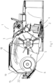
- the cutting unit in fig 1 shows a cutter bar 2 mainly perpendicular to the drive direction with associated cutting discs with knives 4, a rotating treatment unit 3, a transport auger 6 in a bottom tray 5, a hatch 15 and schematically grass 18.
- the direction of rotation for the transport auger is given with the arrow 19.
- the transport auger is further equipped with a scraper edge 22.
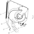
- Fig 2 shows a part of a transport auger unit seen from the outlet opening obliquely from behind.
- the bearing 7 supports the transport auger 6, who in its outer end shows clear finger 9.
- the bearing 7 for the transport auger is carried by a support arm 8, which in its lower part shows a cutting edge 17.
- Beneath the transport auger is also the bottom tray 5 of the auger conveyor seen, to which a number of trigger units 16 are mounted.
- the trigger unit has in turn locking mechanism 13 loaded by the lock spring 12 and pivoted around the swivel point 20.
- the trigger units are interconnected to each other with the torsion bar 14.
- Fig 3 shows a side view of the conveyor seen from the outlet with grass 18 who press against the hatch 15.
- the centreline of the lock spring 12 is shown by a broken line 21.
- Fig 4 shows the same side view but with the lock mechanism 13 and the hatch 15 in open position.
- Fig 5 shows the same side view with the clear finger 9 in two different positions.
- the transport auger operates in the following manner. During work the knives on the cutting disks 4 are cutting the grass, who after is caught by the rotating treatment unit 3 and is thrown backwards against the hatch 15 and is caught by the transport auger 6, who quickly transports the grass in the direction of the outlet opening. As long as the capacity of the transport auger is bigger than the from the treatment unit 3 thrown amount of grass, the pressure against the hatch 15 remain fairly small and the force from the lock springs 12 keeps the lock mechanism 13 and so also the hatch 15 closed.
- the support arm in its external end is equipped with a clear finger 9.
- This clear finger is preferably equipped with an inclined arcuate front edge, which collects the rest material towards the bottom tray 5 to finally cut off the grass against the cutting edge 17 of the support arm 8. In this manner it is prohibited that a long rope of together twisted grass starts to hang on the support arm and disturb the flow of material.
Landscapes
- Engineering & Computer Science (AREA)
- Mechanical Engineering (AREA)
- Life Sciences & Earth Sciences (AREA)
- Environmental Sciences (AREA)
- Harvester Elements (AREA)
- Control Of Conveyors (AREA)
- Safety Devices And Accessories For Harvesting Machines (AREA)
- Filling Or Emptying Of Bunkers, Hoppers, And Tanks (AREA)
- Screw Conveyors (AREA)
Claims (9)
- Mäher (1) zur Verwendung in der Landwirtschaft, wobei der Mäher einen Schneckenförderer zum seitlichen Transport von geschnittenem Gras oder entsprechendem strohartigem Material (18) vom Mäher umfasst, wobei der Schneckenförderer eine Transportschnecke (6) umfasst, die teilweise von einem Gehäuse umschlossen ist, das eine Bodenwanne (5) und eine Luke (15) umfasst,
dadurch gekennzeichnet, dassdie Luke (15) eine Scharnierluke ist, die eine axiale Erstreckung im Haupttransportbereich (19) der Transportschnecke (6) aufweist, unddie Luke (15) Teil eines Überlastungsschutzes ist, der mit mindestens einem Verriegelungsmechanismus (13) zusammenwirkt, der mit einem elastischen Element (12) vorgespannt ist, wobei der Verriegelungsmechanismus angeordnet ist, bei einem einsetzenden Stau von Material (18) gegen die Luke (15), der die Verriegelungskraft des Verriegelungsmechanismus (13) überschreitet, die Luke (15) freizugeben, um das geschnittene Material (18) nach hinten zu leiten. - Mäher (1) nach Anspruch 1, dadurch gekennzeichnet, dass das elastische Element (12) eine Verriegelungsfeder ist.
- Mäher (1) nach Anspruch 2, dadurch gekennzeichnet, dass eine Wirklinie (21) für das elastische Element (12) des Verriegelungsmechanismus (13) bei einem einsetzenden Stau an der Transportschnecke (6) einen Schwenkpunkt (20) des Verriegelungsmechanismus passiert.
- Mäher (1) nach einem oder mehreren der vorhergehenden Ansprüche 1 bis 3, dadurch gekennzeichnet, dass mehrere Verriegelungsmechanismen (13) an einen Torsionsstab (14) gekoppelt sind, derart, dass alle von ihnen bei einem einsetzenden Stau an der Transportschnecke (6) praktisch gleichzeitig öffnen.
- Mäher (1) nach einem oder mehreren der vorhergehenden Ansprüche, dadurch gekennzeichnet, dass sich zwischen der Bodenwanne (5) der Transportschnecke (6) und der Luke (15) parallele Flächen befinden, die angeordnet sind, es zu verhindern, dass das Material (18) austritt, wenn sich die Luke nach außen biegt, bevor der Verriegelungsmechanismus (13) ausgelöst ist.
- Mäher (1) nach einem oder mehreren der vorhergehenden Ansprüche, dadurch gekennzeichnet, dass eine oder mehrere Federn (11) derart mit der Luke (15) verbunden sind, dass nach Freigeben des Verriegelungsmechanismus (13) die Abladeelemente angeordnet sind, die Luke (15) zu öffnen, um eine freie Ausgabe des Materials (18) zu erlauben.
- Mäher (1) nach einem oder mehreren der vorhergehenden Ansprüche, dadurch gekennzeichnet, dass die Luke (15) in einer offenen Position anwendbar ist, um ohne eine Seitenbewegung des geschnittenen Materials (18) zu schneiden.
- Mäher (1) nach einem oder mehreren der vorhergehenden Ansprüche, dadurch gekennzeichnet, dass die Luke (15) angeordnet ist, mit Auslöseeinheiten (16) zusammenzuwirken, wobei die Auslöseeinheiten an der Bodenwanne (5) montiert sind und jede einen der Verriegelungsmechanismen (13) umfasst, die von der entsprechenden elastischen Komponente geladen sind, wobei die elastische Komponente eine Verriegelungsfeder (12) ist, wobei die Auslöseeinheiten um einen Schwenkpunkt (20) schwenkbar sind, wodurch die Auslöseeinheiten mit einem Torsionsstab (14) aneinandergekoppelt sind.
- Mäher (1) nach Anspruch 8, dadurch gekennzeichnet, dass die Auslöseeinheiten (16) aneinandergekoppelt sind, um die Luke (15) vollständig freizugeben, wodurch es dem Gras ermöglicht wird, frei aus der Maschine geworfen zu werden, und die Transportschnecke (6) angeordnet ist, sich selbst zu entleeren, da die vollständig offene Luke angeordnet ist, es der sich drehenden Behandlungseinheit (3) zu ermöglichen, das Gras direkt hinten aus dem Mäher zu werfen.
Applications Claiming Priority (2)
| Application Number | Priority Date | Filing Date | Title |
|---|---|---|---|
| FI20150214A FI20150214A7 (fi) | 2015-07-13 | 2015-07-13 | Kuljetin |
| PCT/FI2016/000019 WO2017009522A1 (en) | 2015-07-13 | 2016-07-06 | Auger conveyor |
Publications (4)
| Publication Number | Publication Date |
|---|---|
| EP3322281A1 EP3322281A1 (de) | 2018-05-23 |
| EP3322281A4 EP3322281A4 (de) | 2019-02-20 |
| EP3322281B1 true EP3322281B1 (de) | 2024-04-17 |
| EP3322281C0 EP3322281C0 (de) | 2024-04-17 |
Family
ID=57756879
Family Applications (1)
| Application Number | Title | Priority Date | Filing Date |
|---|---|---|---|
| EP16823937.4A Active EP3322281B1 (de) | 2015-07-13 | 2016-07-06 | Mäher mit schneckenförderer |
Country Status (5)
| Country | Link |
|---|---|
| EP (1) | EP3322281B1 (de) |
| JP (1) | JP6781755B2 (de) |
| FI (1) | FI20150214A7 (de) |
| PL (1) | PL3322281T3 (de) |
| WO (1) | WO2017009522A1 (de) |
Families Citing this family (4)
| Publication number | Priority date | Publication date | Assignee | Title |
|---|---|---|---|---|
| DE102017010367A1 (de) * | 2017-11-09 | 2019-05-09 | Maschinenfabrik Bernard Krone GmbH & Co. KG | Mähmaschine |
| RU179713U1 (ru) * | 2018-02-20 | 2018-05-23 | Андрей Валентинович Никоноров | Зерноподъемник |
| DE102019123623A1 (de) * | 2019-09-04 | 2021-03-04 | Claas Selbstfahrende Erntemaschinen Gmbh | Entleervorrichtung für ein Erntegutaufnahmebehältnis eines landwirtschaftlichen Fahrzeugs |
| US11591163B1 (en) * | 2021-09-01 | 2023-02-28 | Larry Parsell | Sweep auger shield assembly |
Family Cites Families (15)
| Publication number | Priority date | Publication date | Assignee | Title |
|---|---|---|---|---|
| US622364A (en) | 1899-04-04 | Steam-generator for thawing frozen ground | ||
| JPS4311303Y1 (de) | 1964-02-26 | 1968-05-16 | ||
| NL7907731A (nl) * | 1979-10-19 | 1981-04-22 | Multinorm Bv | Gewas behandelend landbouwwerktuig. |
| FR2494547A1 (fr) | 1980-11-26 | 1982-05-28 | Hesston Sa | Groupeur d'andains pour machine du type faucheuse andaineuse ou faucheuse conditionneuse andaineuse |
| JPS6332612Y2 (de) * | 1981-01-17 | 1988-08-31 | ||
| US4720962A (en) * | 1982-07-29 | 1988-01-26 | National Research Development Corporation | Apparatus for picking up and conveying crop or other material |
| JPS59161939U (ja) * | 1983-04-14 | 1984-10-30 | ヤンマー農機株式会社 | グレンタンクにおける籾移送装置 |
| DE3604691A1 (de) | 1986-02-14 | 1987-08-20 | Claas Saulgau Gmbh | Maehwerk mit querfoerderband |
| JPH04110427U (ja) * | 1991-03-11 | 1992-09-25 | 株式会社大橋 | 自走式草刈機 |
| US5443421A (en) * | 1993-07-20 | 1995-08-22 | Heintzman; Rick | Rock discharge assembly for hay crusher |
| DE19931684C1 (de) | 1999-07-08 | 2000-09-07 | Krone Bernhard Gmbh Maschf | Gerätekombination zum Ernten von landwirtschaftlichem Halmgut |
| FI121695B (sv) | 2009-05-19 | 2011-03-15 | El Ho Ab Oy | Slåttermaskin |
| CA2842973C (en) * | 2013-02-15 | 2017-05-16 | Mark E. Koenig | Pressure relief tube for auger |
| US8967357B2 (en) * | 2013-06-13 | 2015-03-03 | Meridian Manufacturing Inc. | Grain auger blow-out door |
| CN204280599U (zh) * | 2014-11-21 | 2015-04-22 | 河南华裕黑色作物科技开发有限公司 | 一种防溢绞龙 |
-
2015
- 2015-07-13 FI FI20150214A patent/FI20150214A7/fi unknown
-
2016
- 2016-07-06 EP EP16823937.4A patent/EP3322281B1/de active Active
- 2016-07-06 JP JP2018521717A patent/JP6781755B2/ja active Active
- 2016-07-06 WO PCT/FI2016/000019 patent/WO2017009522A1/en not_active Ceased
- 2016-07-06 PL PL16823937.4T patent/PL3322281T3/pl unknown
Also Published As
| Publication number | Publication date |
|---|---|
| JP6781755B2 (ja) | 2020-11-04 |
| WO2017009522A1 (en) | 2017-01-19 |
| FI20150214A (fi) | 2017-01-14 |
| EP3322281A1 (de) | 2018-05-23 |
| JP2018529373A (ja) | 2018-10-11 |
| EP3322281A4 (de) | 2019-02-20 |
| EP3322281C0 (de) | 2024-04-17 |
| FI20150214A7 (fi) | 2017-01-14 |
| PL3322281T3 (pl) | 2024-09-02 |
Similar Documents
| Publication | Publication Date | Title |
|---|---|---|
| EP3417695B1 (de) | System zur vernichtung von samen in ernterückständen vor der entladung aus einer landwirtschaftlichen erntemaschine | |
| US6032444A (en) | Non-row-sensitive forage harvester | |
| EP3322281B1 (de) | Mäher mit schneckenförderer | |
| US7648413B2 (en) | Combine harvester power management control | |
| EP2702861B1 (de) | Schneckenantrieb-Kupplungsanordnung für einen Mähdrescher | |
| US8307620B1 (en) | Rotary disk crop harvesting header with an auger member | |
| US5272861A (en) | Rotary agricultural tool | |
| US7461498B1 (en) | Crop harvesting header with rotary disks and converging system for forming a swath | |
| US9930832B2 (en) | Mower with reconfigurable crop material ejection | |
| US9320198B2 (en) | System and method for controlling a draper header during and after a deslugging or clean out operation | |
| US8147303B2 (en) | Harvested crop chopper remains and distribution arrangement for a combine | |
| EP3016497B1 (de) | Antriebsmechanismussteuerung für eine landwirtschaftliche erntemaschine | |
| US6651412B1 (en) | Forward clutch drive for windrow header with positive reverse drive | |
| US20100071333A1 (en) | Loading auger deflector | |
| US12262660B2 (en) | Agricultural implement for field-collection, pulverization and field-dispersement of flax or hemp straw | |
| EP3280244B1 (de) | Mäher und verfahren zur konfiguration eines mähers zum selektiven entladen von mähgut in respektiven seitwärts- oder rückwärtsrichtungen vom mäher | |
| US9015966B2 (en) | Harvesting device for picking up plants |
Legal Events
| Date | Code | Title | Description |
|---|---|---|---|
| STAA | Information on the status of an ep patent application or granted ep patent |
Free format text: STATUS: THE INTERNATIONAL PUBLICATION HAS BEEN MADE |
|
| PUAI | Public reference made under article 153(3) epc to a published international application that has entered the european phase |
Free format text: ORIGINAL CODE: 0009012 |
|
| STAA | Information on the status of an ep patent application or granted ep patent |
Free format text: STATUS: REQUEST FOR EXAMINATION WAS MADE |
|
| 17P | Request for examination filed |
Effective date: 20180208 |
|
| AK | Designated contracting states |
Kind code of ref document: A1 Designated state(s): AL AT BE BG CH CY CZ DE DK EE ES FI FR GB GR HR HU IE IS IT LI LT LU LV MC MK MT NL NO PL PT RO RS SE SI SK SM TR |
|
| AX | Request for extension of the european patent |
Extension state: BA ME |
|
| DAV | Request for validation of the european patent (deleted) | ||
| DAX | Request for extension of the european patent (deleted) | ||
| A4 | Supplementary search report drawn up and despatched |
Effective date: 20190122 |
|
| RIC1 | Information provided on ipc code assigned before grant |
Ipc: B65G 47/42 20060101ALI20190117BHEP Ipc: B65G 43/08 20060101ALI20190117BHEP Ipc: B65G 33/24 20060101ALI20190117BHEP Ipc: A01D 57/30 20060101ALI20190117BHEP Ipc: B65G 41/00 20060101ALI20190117BHEP Ipc: B65G 33/14 20060101ALI20190117BHEP Ipc: A01D 75/18 20060101AFI20190117BHEP |
|
| STAA | Information on the status of an ep patent application or granted ep patent |
Free format text: STATUS: EXAMINATION IS IN PROGRESS |
|
| 17Q | First examination report despatched |
Effective date: 20200326 |
|
| GRAP | Despatch of communication of intention to grant a patent |
Free format text: ORIGINAL CODE: EPIDOSNIGR1 |
|
| STAA | Information on the status of an ep patent application or granted ep patent |
Free format text: STATUS: GRANT OF PATENT IS INTENDED |
|
| INTG | Intention to grant announced |
Effective date: 20231201 |
|
| RIC1 | Information provided on ipc code assigned before grant |
Ipc: A01D 57/30 20060101ALI20231120BHEP Ipc: B65G 33/14 20060101ALI20231120BHEP Ipc: B65G 33/24 20060101ALI20231120BHEP Ipc: A01D 75/18 20060101AFI20231120BHEP |
|
| GRAS | Grant fee paid |
Free format text: ORIGINAL CODE: EPIDOSNIGR3 |
|
| GRAA | (expected) grant |
Free format text: ORIGINAL CODE: 0009210 |
|
| STAA | Information on the status of an ep patent application or granted ep patent |
Free format text: STATUS: THE PATENT HAS BEEN GRANTED |
|
| AK | Designated contracting states |
Kind code of ref document: B1 Designated state(s): AL AT BE BG CH CY CZ DE DK EE ES FI FR GB GR HR HU IE IS IT LI LT LU LV MC MK MT NL NO PL PT RO RS SE SI SK SM TR |
|
| REG | Reference to a national code |
Ref country code: GB Ref legal event code: FG4D |
|
| REG | Reference to a national code |
Ref country code: CH Ref legal event code: EP |
|
| REG | Reference to a national code |
Ref country code: IE Ref legal event code: FG4D Ref country code: DE Ref legal event code: R096 Ref document number: 602016087011 Country of ref document: DE |
|
| U01 | Request for unitary effect filed |
Effective date: 20240507 |
|
| U07 | Unitary effect registered |
Designated state(s): AT BE BG DE DK EE FI FR IT LT LU LV MT NL PT SE SI Effective date: 20240521 |
|
| U20 | Renewal fee for the european patent with unitary effect paid |
Year of fee payment: 9 Effective date: 20240717 |
|
| PG25 | Lapsed in a contracting state [announced via postgrant information from national office to epo] |
Ref country code: IS Free format text: LAPSE BECAUSE OF FAILURE TO SUBMIT A TRANSLATION OF THE DESCRIPTION OR TO PAY THE FEE WITHIN THE PRESCRIBED TIME-LIMIT Effective date: 20240817 |
|
| PG25 | Lapsed in a contracting state [announced via postgrant information from national office to epo] |
Ref country code: HR Free format text: LAPSE BECAUSE OF FAILURE TO SUBMIT A TRANSLATION OF THE DESCRIPTION OR TO PAY THE FEE WITHIN THE PRESCRIBED TIME-LIMIT Effective date: 20240417 |
|
| PG25 | Lapsed in a contracting state [announced via postgrant information from national office to epo] |
Ref country code: GR Free format text: LAPSE BECAUSE OF FAILURE TO SUBMIT A TRANSLATION OF THE DESCRIPTION OR TO PAY THE FEE WITHIN THE PRESCRIBED TIME-LIMIT Effective date: 20240718 |
|
| PG25 | Lapsed in a contracting state [announced via postgrant information from national office to epo] |
Ref country code: ES Free format text: LAPSE BECAUSE OF FAILURE TO SUBMIT A TRANSLATION OF THE DESCRIPTION OR TO PAY THE FEE WITHIN THE PRESCRIBED TIME-LIMIT Effective date: 20240417 |
|
| PG25 | Lapsed in a contracting state [announced via postgrant information from national office to epo] |
Ref country code: NO Free format text: LAPSE BECAUSE OF FAILURE TO SUBMIT A TRANSLATION OF THE DESCRIPTION OR TO PAY THE FEE WITHIN THE PRESCRIBED TIME-LIMIT Effective date: 20240717 Ref country code: IS Free format text: LAPSE BECAUSE OF FAILURE TO SUBMIT A TRANSLATION OF THE DESCRIPTION OR TO PAY THE FEE WITHIN THE PRESCRIBED TIME-LIMIT Effective date: 20240817 Ref country code: HR Free format text: LAPSE BECAUSE OF FAILURE TO SUBMIT A TRANSLATION OF THE DESCRIPTION OR TO PAY THE FEE WITHIN THE PRESCRIBED TIME-LIMIT Effective date: 20240417 Ref country code: GR Free format text: LAPSE BECAUSE OF FAILURE TO SUBMIT A TRANSLATION OF THE DESCRIPTION OR TO PAY THE FEE WITHIN THE PRESCRIBED TIME-LIMIT Effective date: 20240718 Ref country code: ES Free format text: LAPSE BECAUSE OF FAILURE TO SUBMIT A TRANSLATION OF THE DESCRIPTION OR TO PAY THE FEE WITHIN THE PRESCRIBED TIME-LIMIT Effective date: 20240417 Ref country code: RS Free format text: LAPSE BECAUSE OF FAILURE TO SUBMIT A TRANSLATION OF THE DESCRIPTION OR TO PAY THE FEE WITHIN THE PRESCRIBED TIME-LIMIT Effective date: 20240717 |
|
| REG | Reference to a national code |
Ref country code: DE Ref legal event code: R097 Ref document number: 602016087011 Country of ref document: DE |
|
| PG25 | Lapsed in a contracting state [announced via postgrant information from national office to epo] |
Ref country code: CZ Free format text: LAPSE BECAUSE OF FAILURE TO SUBMIT A TRANSLATION OF THE DESCRIPTION OR TO PAY THE FEE WITHIN THE PRESCRIBED TIME-LIMIT Effective date: 20240417 |
|
| PG25 | Lapsed in a contracting state [announced via postgrant information from national office to epo] |
Ref country code: RO Free format text: LAPSE BECAUSE OF FAILURE TO SUBMIT A TRANSLATION OF THE DESCRIPTION OR TO PAY THE FEE WITHIN THE PRESCRIBED TIME-LIMIT Effective date: 20240417 Ref country code: SK Free format text: LAPSE BECAUSE OF FAILURE TO SUBMIT A TRANSLATION OF THE DESCRIPTION OR TO PAY THE FEE WITHIN THE PRESCRIBED TIME-LIMIT Effective date: 20240417 |
|
| PG25 | Lapsed in a contracting state [announced via postgrant information from national office to epo] |
Ref country code: SM Free format text: LAPSE BECAUSE OF FAILURE TO SUBMIT A TRANSLATION OF THE DESCRIPTION OR TO PAY THE FEE WITHIN THE PRESCRIBED TIME-LIMIT Effective date: 20240417 |
|
| PG25 | Lapsed in a contracting state [announced via postgrant information from national office to epo] |
Ref country code: SM Free format text: LAPSE BECAUSE OF FAILURE TO SUBMIT A TRANSLATION OF THE DESCRIPTION OR TO PAY THE FEE WITHIN THE PRESCRIBED TIME-LIMIT Effective date: 20240417 Ref country code: SK Free format text: LAPSE BECAUSE OF FAILURE TO SUBMIT A TRANSLATION OF THE DESCRIPTION OR TO PAY THE FEE WITHIN THE PRESCRIBED TIME-LIMIT Effective date: 20240417 Ref country code: RO Free format text: LAPSE BECAUSE OF FAILURE TO SUBMIT A TRANSLATION OF THE DESCRIPTION OR TO PAY THE FEE WITHIN THE PRESCRIBED TIME-LIMIT Effective date: 20240417 Ref country code: CZ Free format text: LAPSE BECAUSE OF FAILURE TO SUBMIT A TRANSLATION OF THE DESCRIPTION OR TO PAY THE FEE WITHIN THE PRESCRIBED TIME-LIMIT Effective date: 20240417 |
|
| PG25 | Lapsed in a contracting state [announced via postgrant information from national office to epo] |
Ref country code: MC Free format text: LAPSE BECAUSE OF FAILURE TO SUBMIT A TRANSLATION OF THE DESCRIPTION OR TO PAY THE FEE WITHIN THE PRESCRIBED TIME-LIMIT Effective date: 20240417 |
|
| PLBE | No opposition filed within time limit |
Free format text: ORIGINAL CODE: 0009261 |
|
| STAA | Information on the status of an ep patent application or granted ep patent |
Free format text: STATUS: NO OPPOSITION FILED WITHIN TIME LIMIT |
|
| REG | Reference to a national code |
Ref country code: CH Ref legal event code: PL |
|
| 26N | No opposition filed |
Effective date: 20250120 |
|
| GBPC | Gb: european patent ceased through non-payment of renewal fee |
Effective date: 20240717 |
|
| PG25 | Lapsed in a contracting state [announced via postgrant information from national office to epo] |
Ref country code: CH Free format text: LAPSE BECAUSE OF NON-PAYMENT OF DUE FEES Effective date: 20240731 |
|
| PG25 | Lapsed in a contracting state [announced via postgrant information from national office to epo] |
Ref country code: GB Free format text: LAPSE BECAUSE OF NON-PAYMENT OF DUE FEES Effective date: 20240717 |
|
| PGFP | Annual fee paid to national office [announced via postgrant information from national office to epo] |
Ref country code: PL Payment date: 20250613 Year of fee payment: 10 |
|
| U20 | Renewal fee for the european patent with unitary effect paid |
Year of fee payment: 10 Effective date: 20250715 |
|
| PGFP | Annual fee paid to national office [announced via postgrant information from national office to epo] |
Ref country code: IE Payment date: 20250718 Year of fee payment: 10 |
|
| PG25 | Lapsed in a contracting state [announced via postgrant information from national office to epo] |
Ref country code: CY Free format text: LAPSE BECAUSE OF FAILURE TO SUBMIT A TRANSLATION OF THE DESCRIPTION OR TO PAY THE FEE WITHIN THE PRESCRIBED TIME-LIMIT; INVALID AB INITIO Effective date: 20160706 |
|
| PG25 | Lapsed in a contracting state [announced via postgrant information from national office to epo] |
Ref country code: HU Free format text: LAPSE BECAUSE OF FAILURE TO SUBMIT A TRANSLATION OF THE DESCRIPTION OR TO PAY THE FEE WITHIN THE PRESCRIBED TIME-LIMIT; INVALID AB INITIO Effective date: 20160706 |