EP3322355B1 - Appareil de traitement de plaie ultrasonore - Google Patents
Appareil de traitement de plaie ultrasonore Download PDFInfo
- Publication number
- EP3322355B1 EP3322355B1 EP16824918.3A EP16824918A EP3322355B1 EP 3322355 B1 EP3322355 B1 EP 3322355B1 EP 16824918 A EP16824918 A EP 16824918A EP 3322355 B1 EP3322355 B1 EP 3322355B1
- Authority
- EP
- European Patent Office
- Prior art keywords
- rim
- probe
- distal
- recess
- probe head
- Prior art date
- Legal status (The legal status is an assumption and is not a legal conclusion. Google has not performed a legal analysis and makes no representation as to the accuracy of the status listed.)
- Active
Links
Images
Classifications
-
- A—HUMAN NECESSITIES
- A61—MEDICAL OR VETERINARY SCIENCE; HYGIENE
- A61B—DIAGNOSIS; SURGERY; IDENTIFICATION
- A61B17/00—Surgical instruments, devices or methods
- A61B17/32—Surgical cutting instruments
- A61B17/320068—Surgical cutting instruments using mechanical vibrations, e.g. ultrasonic
-
- A—HUMAN NECESSITIES
- A61—MEDICAL OR VETERINARY SCIENCE; HYGIENE
- A61N—ELECTROTHERAPY; MAGNETOTHERAPY; RADIATION THERAPY; ULTRASOUND THERAPY
- A61N7/00—Ultrasound therapy
-
- A—HUMAN NECESSITIES
- A61—MEDICAL OR VETERINARY SCIENCE; HYGIENE
- A61B—DIAGNOSIS; SURGERY; IDENTIFICATION
- A61B17/00—Surgical instruments, devices or methods
- A61B2017/00743—Type of operation; Specification of treatment sites
- A61B2017/00747—Dermatology
- A61B2017/00761—Removing layer of skin tissue, e.g. wrinkles, scars or cancerous tissue
-
- A—HUMAN NECESSITIES
- A61—MEDICAL OR VETERINARY SCIENCE; HYGIENE
- A61B—DIAGNOSIS; SURGERY; IDENTIFICATION
- A61B17/00—Surgical instruments, devices or methods
- A61B17/32—Surgical cutting instruments
- A61B2017/320004—Surgical cutting instruments abrasive
- A61B2017/320008—Scrapers
-
- A—HUMAN NECESSITIES
- A61—MEDICAL OR VETERINARY SCIENCE; HYGIENE
- A61B—DIAGNOSIS; SURGERY; IDENTIFICATION
- A61B17/00—Surgical instruments, devices or methods
- A61B17/32—Surgical cutting instruments
- A61B17/320068—Surgical cutting instruments using mechanical vibrations, e.g. ultrasonic
- A61B2017/320072—Working tips with special features, e.g. extending parts
-
- A—HUMAN NECESSITIES
- A61—MEDICAL OR VETERINARY SCIENCE; HYGIENE
- A61B—DIAGNOSIS; SURGERY; IDENTIFICATION
- A61B2217/00—General characteristics of surgical instruments
- A61B2217/002—Auxiliary appliance
- A61B2217/007—Auxiliary appliance with irrigation system
-
- A—HUMAN NECESSITIES
- A61—MEDICAL OR VETERINARY SCIENCE; HYGIENE
- A61N—ELECTROTHERAPY; MAGNETOTHERAPY; RADIATION THERAPY; ULTRASOUND THERAPY
- A61N7/00—Ultrasound therapy
- A61N2007/0004—Applications of ultrasound therapy
- A61N2007/0017—Wound healing
-
- A—HUMAN NECESSITIES
- A61—MEDICAL OR VETERINARY SCIENCE; HYGIENE
- A61N—ELECTROTHERAPY; MAGNETOTHERAPY; RADIATION THERAPY; ULTRASOUND THERAPY
- A61N7/00—Ultrasound therapy
- A61N2007/0004—Applications of ultrasound therapy
- A61N2007/0034—Skin treatment
Definitions
- This invention relates to ultrasonic surgical instruments. More particularly, this invention relates to the treatment of wounds with ultrasound energy.
- the treatment contemplated by this disclosure includes fragmentation and emulsification of hard and soft tissue in a clinical environment while reducing unwanted heat and collateral tissue damage.
- European Patent No. 2,066,255 discloses a ultrasonic handpiece for making holes in bone tissue comprising a surgical tool provided with a head adapted to make a hole in the bone.
- the head comprises a plurality of cutting elements defining the profile of the hole to be made in the bone.
- a main channel which ends in an outlet hole opening into the tool head is provided in the body of the tool for the passage of a cooling fluid, so as to cool the working area affected by the tool head.
- U.S. Patent No. 8,118,823 discloses a ultrasonic horn comprising: an elongated member having a proximal end, a distal end and a longitudinal axis, the proximal end being adapted to receive ultrasonic waves from a ultrasonic handpiece; a first land member disposed at an annulus at the distal end of the elongated member, the first land member having a first angle with respect to the longitudinal axis; and a second land member disposed at the annulus, the second land member having a second angle, different from the first angle, with respect to said longitudinal axis.
- Ultrasonic devices which can be used to ablate or cut tissue in surgery are also disclosed by Wuchinich et al. in U.S. Patent No. 4,223,676 and Idemoto et al in U.S. Patent No. 5,188,102 .
- these surgical devices include a blunt tip hollow probe that vibrates at frequencies between 20 kHz and 100 kHz, with amplitudes up to 300 microns or more.
- Such devices ablate tissue by either producing cavitation bubbles which implode and disrupt cells, by generating tissue compression and relaxation stresses (sometimes called the jackhammer effect) or by other mechanisms such as micro streaming of bubbles in the tissue matrix.
- the effect is that the tissue becomes liquefied and separated.
- the fragmented tissue becomes emulsified with an irrigant solution.
- the resulting emulsion or slurry of tissue debris is then aspirated from the site.
- Bulk excision of tissue is possible by applying the energy around and under an unwanted tissue mass to separate it from the surrounding structure. The surgeon can then lift the separated tissue mass out using common tools such as forceps.
- the tubular probe is excited by a transducer of either the piezoelectric or magnetostrictive type that transforms an alternating electrical signal within the frequencies indicated above into a longitudinal or transverse vibration.
- a transducer of either the piezoelectric or magnetostrictive type that transforms an alternating electrical signal within the frequencies indicated above into a longitudinal or transverse vibration.
- the two become a single element with series and parallel resonances.
- the designer will try to tailor the mechanical and electrical characteristics of these elements to provide the proper frequency of operation.
- the elements will have a long axis that is straight and has the tip truncated in a plane perpendicular to the long axis. This is done for simplicity and economic considerations. In almost all applications, whether medical or industrial, such an embodiment is practical and useful.
- the blunt straight probe has been shown to be less effective in removing the hard eschar buildup that occurs when the wound is healing. This eschar buildup must be removed so that the healthy tissue is exposed and allowed to close the wound to provide complete healing with minimal scar tissue formation.
- the small diameter tip since it is cannulated, has a small annular area with limits energy transmission into the wound. This extends the length of the procedure and causes operator fatigue and patient discomfort.
- High temperature burns produce a tough, leathery type of eschar. While the eschar can slough off naturally, its removal through surgical debridement is often necessary in order to prevent infection. This is even more important for immuno-compromised patients.
- a frequently used eschar removal option involves the use of a manual dermatome such as a Week knife. The surgeon cuts thin slices of eschar until the healthy tissue is exposed. Bleeding is the key visual indicator when the Week knife has reached healthy tissue. Ideally, the eschar should be removed without any insult to the healthy tissue below. As this is not possible, the thinner the layer of healthy tissue removed during debridement, the more successful the eschar removal procedure.
- ultrasonic debridement of wounds has already been proven as an extremely precise, necrotic tissue removal method with the added benefit of minimum impact to the healthy tissue.
- Ultrasound wound debridement probes are used for debriding complex tissue topographies with minimal loss of healthy tissue. This is not possible to duplicate with sharps, such as scalpels or Week knives .
- the present invention aims to provide an improved ultrasonic surgical instrument for use in wound treatment. More particularly, the present invention aims to provide such an instrument that will improve wound healing times. Preferably, such an instrument may be easily used in the debridement of wounds that evince a tough, leathery type of eschar.
- An ultrasonic medical treatment probe in accordance with the present invention comprises a shaft or shank, a connector and a probe head.
- the connector disposed at one end of the shaft or shank, is configured for coupling to a source of ultrasonic vibratory energy.
- the probe head is located at an end of the shaft or shank opposite the connector and includes a recess opening onto a distal end plane of the instrument.
- the probe head has a distal-most rim extending along an endless perimeter around the recess and is formed with a series of serrations or teeth.
- the distal-most rim is disposed in a plane, exemplarily, but not necessarily, oriented at a 90° angle relative to an axis of the shaft.
- the rim is circular.
- the probe head has a cup-shaped configuration, and the rim constitutes an edge of the probe head.
- the rim is thin in comparison to the width of the recess. While the rim is no thicker than a few millimeters, the recess is typically 5-15 millimeters in diameter. Thus, the diameter of the recess is roughly an order of magnitude larger than the width of the rim.
- the probe head is provided along the rim with a plurality of notches or openings communicating with the recess.
- the probe head is provided along the rim with exactly four notches or openings communicating with the recess.
- the serrations or teeth extend continuously along an entire circumference of the rim, subject to the spaces formed by the notches or openings. The resulting symmetry facilitates use of the device to debride a wound surface.
- the entire geometry of the probe head is particularly conducive to effective removal of eschar from tissue surfaces having high-temperature burns.
- An exemplary debridement method utilizes an ultrasonic probe having a shaft or shank, a connector at one end of the shaft or shaft configured for coupling to a source of ultrasonic vibratory energy, and a probe head at an end of the shaft or shank opposite the connector, the probe head including a recess opening onto a distal end plane, the probe head having a distal-most rim extending along an endless uninterrupted perimeter around the recess, the rim being formed with a series of serrations or teeth.
- the method comprises placing the rim including the serrations or teeth in contact with a target surface of a patient, moving the probe so that the rim moves in a predetermined pattern parallel to and along the target surface while the rim including the serrations or teeth is in contact with the surface, and, during the moving of the probe, generating an ultrasonic standing wave in the probe to vibrate the rim and thereby debride the target surface.
- liquid is conducted through a channel or bore in the probe shaft to the recess in the probe head during the moving of the probe in contact with the target surface.
- the predetermined pattern of probe motion may be a series of parallel passes adjacent to and preferably overlapping slightly to ensure removal of a continuous layer of eschar at a burn site.
- the same result may be achieved by moving the probe in a series of overlapping loops.
- the loops may be roughly circular and the overlapping circles may be disposed in a linear arrangement to generate a rectangular swath of debrided tissue surface.
- several passes of looping probe movements may be undertaken to debride a wide area.
- the moving of the probe is such that the serrated rim is moved laterally within a plane constituting at least a portion of the target surface.
- the serrated rim of the probe head is vibrated at velocities of 10 to 18 m/s RMS.
- a combination of frequency-amplitude operational parameters may be selected to ensure such velocities. For example, for 22.5 KHz the output amplitude range that produces the desired speed interval of 10-18m/s RMS is 200-360 um.
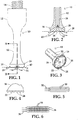
- an ultrasonic medical treatment probe 10 comprises a shaft or shank 12, a connector 14, and a probe head 16.
- Connector 14, disposed at one end of shaft or shank 12, is configured for coupling to a source of ultrasonic vibratory energy.
- Probe head 16 is located at an end of shaft or shank 12 opposite the connector 14 and is transversely enlarged so as to define a large recess 18 opening onto a distal end plane 20 of the instrument.
- Probe head 16 has a distal-most rim 22 extending along an endless or continuous perimeter (a closed loop) around recess 18 and is formed with a series of serrations or teeth 24 pointed or tapering in a distal direction.
- Distal-most rim 22 is disposed in plane 20 that is, exemplarily, but not necessarily, oriented at a 90° angle relative to an axis of shaft 12, i.e. perpendicular thereto.
- rim 12 is circular
- probe head 16 has a cup-shaped configuration
- rim 22 constitutes an edge of the probe head.
- the cup shape is typically cylindrical but may be a right rectangular prism that is longer in one transverse dimension than the other.
- rim 22 is thin in comparison to the width of recess 18. While the rim 22 is no thicker than a few millimeters, the recess is typically at least 5-15 millimeters in diameter. Thus, the diameter of recess 18 is roughly an order of magnitude larger than the width of rim 22.
- Serrations or teeth 24 extend continuously along an entire circumference of rim 22.
- the resulting symmetry facilitates use of the device 10 to debride a wound surface.
- the entire geometry of probe head 16 is particularly conducive to effective removal of eschar from tissue surfaces having high-temperature burns.
- Probe head 16 is provided along rim 22 with a plurality of mutually spaced notches or openings 26 communicating with recess 18. As illustrated, probe head 16 is provided along rim 22 with exactly four notches or openings 26 communicating with recess 18. Thus, while rim 22 of probe head 16 extends along an endless or continuous perimeter around recess 18, the rim is interrupted along that perimeter by notches or openings 26. Serrations or teeth 24 extend continuously along an entire circumference of rim 22 except for the spaces formed by notches or openings 26.
- Shaft or shank 12 is formed with a central channel or bore 28 that communicates at a distal end with recess 18 and penetrates at a proximal end through connector 14 for communicating via a handpiece (not shown) with a pressurized source of irrigation liquid.
- the irrigation liquid is typically a saline solution that may have antibiotic and/or anesthetic constituents.
- An exemplary wound debridement method which does not belong to the invention, utilizing probe 10 entails manipulating the probe to place rim 22 including serrations or teeth 24 in contact with a target surface of a patient, and moving the probe so that the rim moves in a predetermined pattern parallel to and along the target tissue surface while the rim including the serrations or teeth is in contact with the tissue surface.
- one generates an ultrasonic standing wave in the probe to vibrate rim 22 and the serrations or teeth 24 thereof, thereby debriding the target surface.
- Irrigation liquid is conducted through channel or bore 28 in probe shaft 12 to recess 18 in probe head 16 and out through notches 26 (as indicated by arrows 40) during the moving of the probe 10 in contact with the target surface.
- One pattern of probe motion is a series of parallel passes 30 adjacent to each other and preferably overlapping slightly to thereby ensure removal of a continuous or uninterrupted layer of eschar at a burn site.
- the parallel passes 30 may be separate, that is, temporally spaced owing to a lifting of the probe 10 away from the target skin surface and a repositioning of the probe prior to motion in the same direction as indicated by arrows 32.
- alternate passes 30 may be in an opposite direction, with the probe remaining on the target skin surface during the changes in direction of probe motion.
- FIG. 6 Another pattern of probe motion, shown in FIG. 6 , is a series of overlapping loops 34.
- the loops 34 are roughly circular and the overlapping circles may be distributed in arrays 36 to generate linear passes each clearing a rectangular swath or path of debrided tissue surface.
- several debridement passes 36 of looping probe movement may be undertaken to debride a wide area.
- the parallel passes 36 may be separate, that is, temporally spaced owing to a lifting of the probe 10 away from the target skin surface and a repositioning of the probe prior to motion in the same direction as indicated by arrows 38.
- alternate looping passes 36 may be in an opposite direction, with the probe remaining on the target skin surface during the changes in direction of probe motion.
- the moving of probe 10 is such that the serrated rim is moved laterally within a plane constituting at least a portion of the target surface.
- the serrated rim of the probe head is vibrated at velocities of 10 to 18 m/s RMS.
- a combination of frequency-amplitude operational parameters may be selected to ensure such velocities. For example, for 22.5 KHz the output amplitude range that produces the desired speed interval of 10-18m/s RMS is 200-360 um.
- Probe 10 and the use thereof in wound debridement combines the following parameters at the probe-tissue interface: (1) high contact pressure, (2) high velocities of rim 22 and teeth 24, and (3) irrigation via channel 28 and recess 18.
- Probe 10 has proven highly efficient in the precise and efficient removal of tough, leathery type of eschar produced by high temperature burns.
- Key elements of probe 10 include an annular contact area fitted with serrated edge 22 to ensure a high contact pressure, needed for tissue penetration and disruption, at the probe-tissue interface.
- an optimal operation of probe 10 contemplates a combination of frequency-amplitude operational parameters that ensure high velocities exemplarily between 10 and 18m/s RMS.
- rim 22 has a shape other than circular, for instance, oval or elliptical or oblong with rounded or truncated corners. Accordingly, it is to be understood that the drawings and descriptions herein are proffered by way of example to facilitate comprehension of the invention and should not be construed to limit the scope thereof.
Landscapes
- Health & Medical Sciences (AREA)
- Life Sciences & Earth Sciences (AREA)
- Engineering & Computer Science (AREA)
- Surgery (AREA)
- Public Health (AREA)
- Animal Behavior & Ethology (AREA)
- General Health & Medical Sciences (AREA)
- Nuclear Medicine, Radiotherapy & Molecular Imaging (AREA)
- Veterinary Medicine (AREA)
- Biomedical Technology (AREA)
- Dentistry (AREA)
- Mechanical Engineering (AREA)
- Heart & Thoracic Surgery (AREA)
- Medical Informatics (AREA)
- Molecular Biology (AREA)
- Radiology & Medical Imaging (AREA)
- Surgical Instruments (AREA)
Claims (4)
- Une sonde à ultrasons de traitement médical comprenant:un arbre ou queue (12) ;un connecteur (14) au niveau d'une extrémité dudit arbre ou queue (12) configuré pour s'accoupler avec une source d'énergie vibratoire ultrasonique ; etune tête de sonde (16) au niveau d'une extrémité dudit arbre ou queue (12) opposée audit connecteur (14),ladite tête de sonde (16) comprenant un renfoncement (18) s'ouvrant sur un plan distal d'extrémité, ladite tête de sonde (16) ayant une bordure la plus distale (22) s'étendant le long d'un périmètre sans fin ou continu autour dudit renfoncement (18), ladite bordure la plus distale (22) étant formée d'une série de dentelures ou dents (24),ladite tête de sonde (16) étant dotée le long de ladite bordure la plus distale (22) d'une pluralité d'encoches ou ouvertures mutuellement espacées (26) communiquant avec ledit renfoncement (18) et interrompant ledit périmètre sans fin ou continu autour dudit renfoncement (18), lesdites dentelures ou dents (24) s'étendent de façon continue le long de toute la circonférence de ladite bordure la plus distale (22) à l'exception des espaces formés par lesdites encoches ou ouvertures (26),caractérisée en ce que ladite bordure la plus distale (22) constitue un bord de ladite tête de sonde (16) qui a une configuration en forme de coupe avec une surface concave définissant ledit renfoncement (18) et avec ladite bordure la plus distale (22) qui est mince par rapport à la largeur dudit renfoncement (18), de sorte que le diamètre dudit renfoncement (18) est à peu près d'un ordre de grandeur supérieur à la largeur de ladite bordure la plus distale (22).
- La sonde selon la revendication 1, dans laquelle ladite bordure la plus distale (22) est disposée dans ledit plan distal d'extrémité perpendiculaire à un axe longitudinal dudit arbre ou queue (12).
- La sonde selon la revendication 1 ou 2, dans laquelle ladite bordure la plus distale (22) est circulaire.
- La sonde selon l'une quelconque des revendications précédentes, dans laquelle ladite tête de sonde (16) est dotée le long de ladite bordure la plus distale (22) exactement de quatre encoches ou ouvertures (26) communiquant avec ledit renfoncement (18).
Applications Claiming Priority (2)
| Application Number | Priority Date | Filing Date | Title |
|---|---|---|---|
| US14/797,660 US9872697B2 (en) | 2015-07-13 | 2015-07-13 | Ultrasonic wound treatment apparatus and associated method |
| PCT/US2016/041310 WO2017011263A1 (fr) | 2015-07-13 | 2016-07-07 | Appareil de traitement de plaie ultrasonore et procédé associé |
Publications (3)
| Publication Number | Publication Date |
|---|---|
| EP3322355A1 EP3322355A1 (fr) | 2018-05-23 |
| EP3322355A4 EP3322355A4 (fr) | 2019-02-20 |
| EP3322355B1 true EP3322355B1 (fr) | 2021-11-03 |
Family
ID=57757421
Family Applications (1)
| Application Number | Title | Priority Date | Filing Date |
|---|---|---|---|
| EP16824918.3A Active EP3322355B1 (fr) | 2015-07-13 | 2016-07-07 | Appareil de traitement de plaie ultrasonore |
Country Status (7)
| Country | Link |
|---|---|
| US (2) | US9872697B2 (fr) |
| EP (1) | EP3322355B1 (fr) |
| JP (1) | JP2018520787A (fr) |
| CN (1) | CN107847240B (fr) |
| CA (1) | CA2992121C (fr) |
| ES (1) | ES2905217T3 (fr) |
| WO (1) | WO2017011263A1 (fr) |
Families Citing this family (12)
| Publication number | Priority date | Publication date | Assignee | Title |
|---|---|---|---|---|
| US10405875B2 (en) | 2016-05-05 | 2019-09-10 | Misonix, Incorporated | Ultrasonic surgical instrument and method for manufacturing same |
| USD882790S1 (en) * | 2018-01-31 | 2020-04-28 | Beijing Smtp Technology Co., Ltd. | Ultrasonic cutter head |
| USD882793S1 (en) * | 2018-01-31 | 2020-04-28 | Beijing Smtp Technology Co., Ltd. | Ultrasonic cutter head |
| USD882084S1 (en) * | 2018-01-31 | 2020-04-21 | Beijing Smtp Technology Co., Ltd. | Ultrasonic cutter head |
| USD882788S1 (en) * | 2018-01-31 | 2020-04-28 | Beijing Smtp Technology Co., Ltd. | Ultrasonic cutter head |
| USD882787S1 (en) * | 2018-01-31 | 2020-04-28 | Beijing Smtp Technology Co., Ltd. | Ultrasonic cutter head |
| GB2578089B (en) | 2018-09-25 | 2022-10-05 | Radley Scient Limited | Orthopaedic cement removal tools and method |
| US12544089B1 (en) | 2019-12-24 | 2026-02-10 | Farrow Medtech Llc | Wound-care apparatus and method for cleansing, desloughing, and debriding wounds |
| US11980383B2 (en) | 2019-12-24 | 2024-05-14 | Farrow Medtech Llc | Wound-care apparatus and method for cleansing, desloughing, and debriding wounds |
| US12279787B2 (en) | 2020-02-27 | 2025-04-22 | Misonix, Llc | Spinal surgery method |
| US12402905B2 (en) | 2021-08-13 | 2025-09-02 | Misonix, Llc | Serrated ultrasonic cutting blade with varied tooth pitch |
| US12594091B2 (en) | 2022-01-03 | 2026-04-07 | Misonix, Llc | Ultrasonic surgical instrument with probe at angle to handpiece |
Family Cites Families (18)
| Publication number | Priority date | Publication date | Assignee | Title |
|---|---|---|---|---|
| US4223676A (en) | 1977-12-19 | 1980-09-23 | Cavitron Corporation | Ultrasonic aspirator |
| JPH0529696Y2 (fr) * | 1988-11-28 | 1993-07-29 | ||
| JP3011730B2 (ja) * | 1990-02-13 | 2000-02-21 | 住友ベークライト株式会社 | 超音波手術器用ホーン |
| CA2042006C (fr) | 1990-05-11 | 1995-08-29 | Morito Idemoto | Corne a ultrasons pour interventions chirurgicales |
| US20040181185A1 (en) * | 2003-03-14 | 2004-09-16 | Yi-Chang Lee | Device for removing diseased surface tissues |
| US8512340B2 (en) * | 2004-07-02 | 2013-08-20 | Stryker Corporation | Torsional pineapple dissection tip |
| US7931611B2 (en) | 2005-03-23 | 2011-04-26 | Misonix, Incorporated | Ultrasonic wound debrider probe and method of use |
| US20070149881A1 (en) * | 2005-12-22 | 2007-06-28 | Rabin Barry H | Ultrasonically Powered Medical Devices and Systems, and Methods and Uses Thereof |
| US7431704B2 (en) * | 2006-06-07 | 2008-10-07 | Bacoustics, Llc | Apparatus and method for the treatment of tissue with ultrasound energy by direct contact |
| US20080058775A1 (en) | 2006-08-29 | 2008-03-06 | Darian Alexander L | Ultrasonic debrider probe and method of use |
| DE602006015109D1 (de) | 2006-09-25 | 2010-08-05 | Piezosurgery S R L | Handstück mit operationswerkzeug zur anbringung von löchern in knochengeweben |
| JP2008119250A (ja) * | 2006-11-13 | 2008-05-29 | Miwatec:Kk | 超音波手術器用ハンドピースおよびホーン |
| US7682360B2 (en) | 2006-12-07 | 2010-03-23 | Tyco Healthcare Group Lp | Bipolar tissue debrider and method |
| US8118823B2 (en) * | 2008-06-12 | 2012-02-21 | Integra Lifesciences (Ireland) Ltd. | Shear stress ultrasonic horn for ultrasonic surgical aspiration |
| US9259234B2 (en) * | 2010-02-11 | 2016-02-16 | Ethicon Endo-Surgery, Llc | Ultrasonic surgical instruments with rotatable blade and hollow sheath arrangements |
| WO2012054882A1 (fr) | 2010-10-21 | 2012-04-26 | Kci Licensing, Inc. | Outil à main de débridement |
| CN104338246A (zh) * | 2013-07-25 | 2015-02-11 | 厚凯(北京)医疗科技有限公司 | 一种提高急性伤口清创效率的超声波装置 |
| CN104368246A (zh) | 2014-11-10 | 2015-02-25 | 苏州蔻美新材料有限公司 | 一种聚丙烯腈/醋酸纤维复合血液透析膜及其制备方法 |
-
2015
- 2015-07-13 US US14/797,660 patent/US9872697B2/en active Active
-
2016
- 2016-07-07 CN CN201680041420.1A patent/CN107847240B/zh active Active
- 2016-07-07 ES ES16824918T patent/ES2905217T3/es active Active
- 2016-07-07 JP JP2018501284A patent/JP2018520787A/ja active Pending
- 2016-07-07 CA CA2992121A patent/CA2992121C/fr active Active
- 2016-07-07 WO PCT/US2016/041310 patent/WO2017011263A1/fr not_active Ceased
- 2016-07-07 EP EP16824918.3A patent/EP3322355B1/fr active Active
-
2018
- 2018-01-17 US US15/873,607 patent/US10675052B2/en active Active
Non-Patent Citations (1)
| Title |
|---|
| None * |
Also Published As
| Publication number | Publication date |
|---|---|
| US10675052B2 (en) | 2020-06-09 |
| WO2017011263A1 (fr) | 2017-01-19 |
| US20180214174A1 (en) | 2018-08-02 |
| HK1250000A1 (zh) | 2018-11-23 |
| US9872697B2 (en) | 2018-01-23 |
| CA2992121A1 (fr) | 2017-01-19 |
| ES2905217T3 (es) | 2022-04-07 |
| EP3322355A1 (fr) | 2018-05-23 |
| JP2018520787A (ja) | 2018-08-02 |
| CN107847240B (zh) | 2021-06-01 |
| EP3322355A4 (fr) | 2019-02-20 |
| CN107847240A (zh) | 2018-03-27 |
| CA2992121C (fr) | 2023-11-07 |
| US20170014151A1 (en) | 2017-01-19 |
Similar Documents
| Publication | Publication Date | Title |
|---|---|---|
| EP3322355B1 (fr) | Appareil de traitement de plaie ultrasonore | |
| US8430897B2 (en) | Ultrasonic wound debrider probe and method of use | |
| CA2602485C (fr) | Sonde a ultrasons de debridement de plaies et procede d'utilisation de celle-ci | |
| US10980564B2 (en) | Ultrasonic debrider probe | |
| WO2008048386A2 (fr) | Sonde ultrasonique de débridement de plaies et procédé d'utilisation | |
| JP2018143809A (ja) | 超音波器具アセンブリ及びその製造方法 | |
| US20130231528A1 (en) | Protective sleeve and associated surgical method | |
| WO2009088390A1 (fr) | Sonde à débridement par ultrasons | |
| CA2711770C (fr) | Sonde a ultrasons de debridement de plaies et procede d'utilisation | |
| HK1250000B (zh) | 超声波伤口处理装置及相关方法 | |
| HK1231352B (zh) | 超声清创探头 | |
| WO2008027222A2 (fr) | sonde de débridement ultrasonique |
Legal Events
| Date | Code | Title | Description |
|---|---|---|---|
| STAA | Information on the status of an ep patent application or granted ep patent |
Free format text: STATUS: THE INTERNATIONAL PUBLICATION HAS BEEN MADE |
|
| PUAI | Public reference made under article 153(3) epc to a published international application that has entered the european phase |
Free format text: ORIGINAL CODE: 0009012 |
|
| STAA | Information on the status of an ep patent application or granted ep patent |
Free format text: STATUS: REQUEST FOR EXAMINATION WAS MADE |
|
| 17P | Request for examination filed |
Effective date: 20180209 |
|
| AK | Designated contracting states |
Kind code of ref document: A1 Designated state(s): AL AT BE BG CH CY CZ DE DK EE ES FI FR GB GR HR HU IE IS IT LI LT LU LV MC MK MT NL NO PL PT RO RS SE SI SK SM TR |
|
| AX | Request for extension of the european patent |
Extension state: BA ME |
|
| DAV | Request for validation of the european patent (deleted) | ||
| DAX | Request for extension of the european patent (deleted) | ||
| A4 | Supplementary search report drawn up and despatched |
Effective date: 20190123 |
|
| RIC1 | Information provided on ipc code assigned before grant |
Ipc: A61B 17/00 20060101ALN20190117BHEP Ipc: A61B 17/32 20060101AFI20190117BHEP |
|
| STAA | Information on the status of an ep patent application or granted ep patent |
Free format text: STATUS: EXAMINATION IS IN PROGRESS |
|
| 17Q | First examination report despatched |
Effective date: 20191120 |
|
| REG | Reference to a national code |
Ref country code: DE Ref legal event code: R079 Ref document number: 602016065807 Country of ref document: DE Free format text: PREVIOUS MAIN CLASS: A61B0017220000 Ipc: A61B0017320000 |
|
| RIC1 | Information provided on ipc code assigned before grant |
Ipc: A61B 17/00 20060101ALN20210413BHEP Ipc: A61B 17/32 20060101AFI20210413BHEP |
|
| GRAP | Despatch of communication of intention to grant a patent |
Free format text: ORIGINAL CODE: EPIDOSNIGR1 |
|
| STAA | Information on the status of an ep patent application or granted ep patent |
Free format text: STATUS: GRANT OF PATENT IS INTENDED |
|
| INTG | Intention to grant announced |
Effective date: 20210527 |
|
| GRAS | Grant fee paid |
Free format text: ORIGINAL CODE: EPIDOSNIGR3 |
|
| GRAA | (expected) grant |
Free format text: ORIGINAL CODE: 0009210 |
|
| STAA | Information on the status of an ep patent application or granted ep patent |
Free format text: STATUS: THE PATENT HAS BEEN GRANTED |
|
| AK | Designated contracting states |
Kind code of ref document: B1 Designated state(s): AL AT BE BG CH CY CZ DE DK EE ES FI FR GB GR HR HU IE IS IT LI LT LU LV MC MK MT NL NO PL PT RO RS SE SI SK SM TR |
|
| REG | Reference to a national code |
Ref country code: GB Ref legal event code: FG4D |
|
| REG | Reference to a national code |
Ref country code: AT Ref legal event code: REF Ref document number: 1443282 Country of ref document: AT Kind code of ref document: T Effective date: 20211115 Ref country code: CH Ref legal event code: EP |
|
| REG | Reference to a national code |
Ref country code: DE Ref legal event code: R096 Ref document number: 602016065807 Country of ref document: DE |
|
| REG | Reference to a national code |
Ref country code: IE Ref legal event code: FG4D |
|
| REG | Reference to a national code |
Ref country code: LT Ref legal event code: MG9D |
|
| REG | Reference to a national code |
Ref country code: NL Ref legal event code: MP Effective date: 20211103 |
|
| REG | Reference to a national code |
Ref country code: AT Ref legal event code: MK05 Ref document number: 1443282 Country of ref document: AT Kind code of ref document: T Effective date: 20211103 |
|
| REG | Reference to a national code |
Ref country code: ES Ref legal event code: FG2A Ref document number: 2905217 Country of ref document: ES Kind code of ref document: T3 Effective date: 20220407 |
|
| PG25 | Lapsed in a contracting state [announced via postgrant information from national office to epo] |
Ref country code: RS Free format text: LAPSE BECAUSE OF FAILURE TO SUBMIT A TRANSLATION OF THE DESCRIPTION OR TO PAY THE FEE WITHIN THE PRESCRIBED TIME-LIMIT Effective date: 20211103 Ref country code: LT Free format text: LAPSE BECAUSE OF FAILURE TO SUBMIT A TRANSLATION OF THE DESCRIPTION OR TO PAY THE FEE WITHIN THE PRESCRIBED TIME-LIMIT Effective date: 20211103 Ref country code: FI Free format text: LAPSE BECAUSE OF FAILURE TO SUBMIT A TRANSLATION OF THE DESCRIPTION OR TO PAY THE FEE WITHIN THE PRESCRIBED TIME-LIMIT Effective date: 20211103 Ref country code: BG Free format text: LAPSE BECAUSE OF FAILURE TO SUBMIT A TRANSLATION OF THE DESCRIPTION OR TO PAY THE FEE WITHIN THE PRESCRIBED TIME-LIMIT Effective date: 20220203 Ref country code: AT Free format text: LAPSE BECAUSE OF FAILURE TO SUBMIT A TRANSLATION OF THE DESCRIPTION OR TO PAY THE FEE WITHIN THE PRESCRIBED TIME-LIMIT Effective date: 20211103 |
|
| PG25 | Lapsed in a contracting state [announced via postgrant information from national office to epo] |
Ref country code: IS Free format text: LAPSE BECAUSE OF FAILURE TO SUBMIT A TRANSLATION OF THE DESCRIPTION OR TO PAY THE FEE WITHIN THE PRESCRIBED TIME-LIMIT Effective date: 20220303 Ref country code: SE Free format text: LAPSE BECAUSE OF FAILURE TO SUBMIT A TRANSLATION OF THE DESCRIPTION OR TO PAY THE FEE WITHIN THE PRESCRIBED TIME-LIMIT Effective date: 20211103 Ref country code: PT Free format text: LAPSE BECAUSE OF FAILURE TO SUBMIT A TRANSLATION OF THE DESCRIPTION OR TO PAY THE FEE WITHIN THE PRESCRIBED TIME-LIMIT Effective date: 20220303 Ref country code: PL Free format text: LAPSE BECAUSE OF FAILURE TO SUBMIT A TRANSLATION OF THE DESCRIPTION OR TO PAY THE FEE WITHIN THE PRESCRIBED TIME-LIMIT Effective date: 20211103 Ref country code: NO Free format text: LAPSE BECAUSE OF FAILURE TO SUBMIT A TRANSLATION OF THE DESCRIPTION OR TO PAY THE FEE WITHIN THE PRESCRIBED TIME-LIMIT Effective date: 20220203 Ref country code: NL Free format text: LAPSE BECAUSE OF FAILURE TO SUBMIT A TRANSLATION OF THE DESCRIPTION OR TO PAY THE FEE WITHIN THE PRESCRIBED TIME-LIMIT Effective date: 20211103 Ref country code: LV Free format text: LAPSE BECAUSE OF FAILURE TO SUBMIT A TRANSLATION OF THE DESCRIPTION OR TO PAY THE FEE WITHIN THE PRESCRIBED TIME-LIMIT Effective date: 20211103 Ref country code: HR Free format text: LAPSE BECAUSE OF FAILURE TO SUBMIT A TRANSLATION OF THE DESCRIPTION OR TO PAY THE FEE WITHIN THE PRESCRIBED TIME-LIMIT Effective date: 20211103 Ref country code: GR Free format text: LAPSE BECAUSE OF FAILURE TO SUBMIT A TRANSLATION OF THE DESCRIPTION OR TO PAY THE FEE WITHIN THE PRESCRIBED TIME-LIMIT Effective date: 20220204 |
|
| PG25 | Lapsed in a contracting state [announced via postgrant information from national office to epo] |
Ref country code: SM Free format text: LAPSE BECAUSE OF FAILURE TO SUBMIT A TRANSLATION OF THE DESCRIPTION OR TO PAY THE FEE WITHIN THE PRESCRIBED TIME-LIMIT Effective date: 20211103 Ref country code: SK Free format text: LAPSE BECAUSE OF FAILURE TO SUBMIT A TRANSLATION OF THE DESCRIPTION OR TO PAY THE FEE WITHIN THE PRESCRIBED TIME-LIMIT Effective date: 20211103 Ref country code: RO Free format text: LAPSE BECAUSE OF FAILURE TO SUBMIT A TRANSLATION OF THE DESCRIPTION OR TO PAY THE FEE WITHIN THE PRESCRIBED TIME-LIMIT Effective date: 20211103 Ref country code: EE Free format text: LAPSE BECAUSE OF FAILURE TO SUBMIT A TRANSLATION OF THE DESCRIPTION OR TO PAY THE FEE WITHIN THE PRESCRIBED TIME-LIMIT Effective date: 20211103 Ref country code: DK Free format text: LAPSE BECAUSE OF FAILURE TO SUBMIT A TRANSLATION OF THE DESCRIPTION OR TO PAY THE FEE WITHIN THE PRESCRIBED TIME-LIMIT Effective date: 20211103 Ref country code: CZ Free format text: LAPSE BECAUSE OF FAILURE TO SUBMIT A TRANSLATION OF THE DESCRIPTION OR TO PAY THE FEE WITHIN THE PRESCRIBED TIME-LIMIT Effective date: 20211103 |
|
| REG | Reference to a national code |
Ref country code: DE Ref legal event code: R097 Ref document number: 602016065807 Country of ref document: DE |
|
| PLBE | No opposition filed within time limit |
Free format text: ORIGINAL CODE: 0009261 |
|
| STAA | Information on the status of an ep patent application or granted ep patent |
Free format text: STATUS: NO OPPOSITION FILED WITHIN TIME LIMIT |
|
| 26N | No opposition filed |
Effective date: 20220804 |
|
| PG25 | Lapsed in a contracting state [announced via postgrant information from national office to epo] |
Ref country code: AL Free format text: LAPSE BECAUSE OF FAILURE TO SUBMIT A TRANSLATION OF THE DESCRIPTION OR TO PAY THE FEE WITHIN THE PRESCRIBED TIME-LIMIT Effective date: 20211103 |
|
| PG25 | Lapsed in a contracting state [announced via postgrant information from national office to epo] |
Ref country code: SI Free format text: LAPSE BECAUSE OF FAILURE TO SUBMIT A TRANSLATION OF THE DESCRIPTION OR TO PAY THE FEE WITHIN THE PRESCRIBED TIME-LIMIT Effective date: 20211103 |
|
| PG25 | Lapsed in a contracting state [announced via postgrant information from national office to epo] |
Ref country code: MC Free format text: LAPSE BECAUSE OF FAILURE TO SUBMIT A TRANSLATION OF THE DESCRIPTION OR TO PAY THE FEE WITHIN THE PRESCRIBED TIME-LIMIT Effective date: 20211103 |
|
| REG | Reference to a national code |
Ref country code: CH Ref legal event code: PL |
|
| REG | Reference to a national code |
Ref country code: BE Ref legal event code: MM Effective date: 20220731 |
|
| PG25 | Lapsed in a contracting state [announced via postgrant information from national office to epo] |
Ref country code: LU Free format text: LAPSE BECAUSE OF NON-PAYMENT OF DUE FEES Effective date: 20220707 Ref country code: LI Free format text: LAPSE BECAUSE OF NON-PAYMENT OF DUE FEES Effective date: 20220731 Ref country code: CH Free format text: LAPSE BECAUSE OF NON-PAYMENT OF DUE FEES Effective date: 20220731 |
|
| PG25 | Lapsed in a contracting state [announced via postgrant information from national office to epo] |
Ref country code: BE Free format text: LAPSE BECAUSE OF NON-PAYMENT OF DUE FEES Effective date: 20220731 |
|
| PG25 | Lapsed in a contracting state [announced via postgrant information from national office to epo] |
Ref country code: IE Free format text: LAPSE BECAUSE OF NON-PAYMENT OF DUE FEES Effective date: 20220707 |
|
| PG25 | Lapsed in a contracting state [announced via postgrant information from national office to epo] |
Ref country code: HU Free format text: LAPSE BECAUSE OF FAILURE TO SUBMIT A TRANSLATION OF THE DESCRIPTION OR TO PAY THE FEE WITHIN THE PRESCRIBED TIME-LIMIT; INVALID AB INITIO Effective date: 20160707 |
|
| PG25 | Lapsed in a contracting state [announced via postgrant information from national office to epo] |
Ref country code: MK Free format text: LAPSE BECAUSE OF FAILURE TO SUBMIT A TRANSLATION OF THE DESCRIPTION OR TO PAY THE FEE WITHIN THE PRESCRIBED TIME-LIMIT Effective date: 20211103 Ref country code: CY Free format text: LAPSE BECAUSE OF FAILURE TO SUBMIT A TRANSLATION OF THE DESCRIPTION OR TO PAY THE FEE WITHIN THE PRESCRIBED TIME-LIMIT Effective date: 20211103 |
|
| PG25 | Lapsed in a contracting state [announced via postgrant information from national office to epo] |
Ref country code: MT Free format text: LAPSE BECAUSE OF FAILURE TO SUBMIT A TRANSLATION OF THE DESCRIPTION OR TO PAY THE FEE WITHIN THE PRESCRIBED TIME-LIMIT Effective date: 20211103 |
|
| P01 | Opt-out of the competence of the unified patent court (upc) registered |
Free format text: CASE NUMBER: APP_54252/2024 Effective date: 20241001 |
|
| PGFP | Annual fee paid to national office [announced via postgrant information from national office to epo] |
Ref country code: ES Payment date: 20250801 Year of fee payment: 10 |
|
| PGFP | Annual fee paid to national office [announced via postgrant information from national office to epo] |
Ref country code: DE Payment date: 20250729 Year of fee payment: 10 |
|
| PGFP | Annual fee paid to national office [announced via postgrant information from national office to epo] |
Ref country code: IT Payment date: 20250721 Year of fee payment: 10 |
|
| PGFP | Annual fee paid to national office [announced via postgrant information from national office to epo] |
Ref country code: GB Payment date: 20250728 Year of fee payment: 10 |
|
| PGFP | Annual fee paid to national office [announced via postgrant information from national office to epo] |
Ref country code: FR Payment date: 20250725 Year of fee payment: 10 |
|
| PG25 | Lapsed in a contracting state [announced via postgrant information from national office to epo] |
Ref country code: TR Free format text: LAPSE BECAUSE OF FAILURE TO SUBMIT A TRANSLATION OF THE DESCRIPTION OR TO PAY THE FEE WITHIN THE PRESCRIBED TIME-LIMIT Effective date: 20211103 |