EP3322540B1 - Dispositif de changement et système de revêtement pour le revêtement d'objets - Google Patents
Dispositif de changement et système de revêtement pour le revêtement d'objets Download PDFInfo
- Publication number
- EP3322540B1 EP3322540B1 EP16730331.2A EP16730331A EP3322540B1 EP 3322540 B1 EP3322540 B1 EP 3322540B1 EP 16730331 A EP16730331 A EP 16730331A EP 3322540 B1 EP3322540 B1 EP 3322540B1
- Authority
- EP
- European Patent Office
- Prior art keywords
- line
- supply line
- supply
- pressure
- medium
- Prior art date
- Legal status (The legal status is an assumption and is not a legal conclusion. Google has not performed a legal analysis and makes no representation as to the accuracy of the status listed.)
- Active
Links
Images

Classifications
-
- B—PERFORMING OPERATIONS; TRANSPORTING
- B05—SPRAYING OR ATOMISING IN GENERAL; APPLYING FLUENT MATERIALS TO SURFACES, IN GENERAL
- B05B—SPRAYING APPARATUS; ATOMISING APPARATUS; NOZZLES
- B05B12/00—Arrangements for controlling delivery; Arrangements for controlling the spray area
- B05B12/14—Arrangements for controlling delivery; Arrangements for controlling the spray area for supplying a selected one of a plurality of liquids or other fluent materials or several in selected proportions to a spray apparatus, e.g. to a single spray outlet
- B05B12/1481—Arrangements for controlling delivery; Arrangements for controlling the spray area for supplying a selected one of a plurality of liquids or other fluent materials or several in selected proportions to a spray apparatus, e.g. to a single spray outlet comprising pigs, i.e. movable elements sealingly received in supply pipes, for separating different fluids, e.g. liquid coating materials from solvent or air
-
- B—PERFORMING OPERATIONS; TRANSPORTING
- B05—SPRAYING OR ATOMISING IN GENERAL; APPLYING FLUENT MATERIALS TO SURFACES, IN GENERAL
- B05B—SPRAYING APPARATUS; ATOMISING APPARATUS; NOZZLES
- B05B12/00—Arrangements for controlling delivery; Arrangements for controlling the spray area
- B05B12/14—Arrangements for controlling delivery; Arrangements for controlling the spray area for supplying a selected one of a plurality of liquids or other fluent materials or several in selected proportions to a spray apparatus, e.g. to a single spray outlet
-
- B—PERFORMING OPERATIONS; TRANSPORTING
- B05—SPRAYING OR ATOMISING IN GENERAL; APPLYING FLUENT MATERIALS TO SURFACES, IN GENERAL
- B05B—SPRAYING APPARATUS; ATOMISING APPARATUS; NOZZLES
- B05B12/00—Arrangements for controlling delivery; Arrangements for controlling the spray area
- B05B12/14—Arrangements for controlling delivery; Arrangements for controlling the spray area for supplying a selected one of a plurality of liquids or other fluent materials or several in selected proportions to a spray apparatus, e.g. to a single spray outlet
- B05B12/149—Arrangements for controlling delivery; Arrangements for controlling the spray area for supplying a selected one of a plurality of liquids or other fluent materials or several in selected proportions to a spray apparatus, e.g. to a single spray outlet characterised by colour change manifolds or valves therefor
Definitions
- Such a changing device is from WO 2015/022061 A1 known.
- lines are to be understood as meaning all flow paths for fluid media.
- these also include channels, flow spaces or just through openings incorporated into the body.
- a reservoir for a medium is to be understood as meaning any material source for a medium.
- This can be a container, such as a paint tank or the like, but also media-carrying lines, such as are present in ring line systems in a manner known per se.
- Such coating systems are used, for example, in the automobile industry to coat objects such as vehicle bodies or body parts with the aid of electrostatically operating application devices.
- the coating material e.g. a paint
- the coating material is released from the application device and exposed to an electric field in which the coating material is ionized and transported to the object due to electrostatic forces, which is at ground potential for this purpose.
- Such an application device can be, for example, a high-speed rotation atomizer with a rotating bell cup, from which the smallest droplets of paint are thrown off, so that a paint mist is formed.
- Pig technology in which a sliding body, a so-called pig, pushes a volume of material in front of it, has become established for conveying paint and other liquid materials through lines.
- the pig is acted upon on the side remote from the delivery volume with a pressurized fluid, which can be, for example, compressed air or a cleaning fluid, which cleans the line behind the pig.
- a pressurized fluid which can be, for example, compressed air or a cleaning fluid, which cleans the line behind the pig.
- So-called ring lines are generally available as material sources or reservoirs for the coating material, with a fluid connection between a material-carrying ring line and the piggable supply line being able to be established by means of the supply unit.
- the material is first pushed into the system by its own pressure, which prevails in the material sources, ie the ring lines.
- the line section to the application device is quite long and can have a relatively small diameter, at least in sections, which can be around 1 mm, for example. Due to this relatively small diameter, there is a pressure loss along the line, which makes it difficult to convey the material solely through the inherent pressure of the connected material source. In addition, the inherent pressure in the material sources is usually not constant, but is subject to technical, irregular fluctuations, which also makes it difficult to reproduce the volume conveyed.
- the coupling connection can be connected directly to the feed line by means of a valve arrangement in such a way that the medium can be routed past the delivery pressure device.
- the existing delivery pressure device allows the medium to be fed into the feed line with a specified and reproducible delivery pressure, so that pressure fluctuations in the material sources only represent a negligible irregularity.
- a sufficiently high delivery pressure can be built up on the medium, so that possible pressure losses along the delivery route to the application device can also be compensated.
- the delivery pressure device can cause or support close to the connection of the changing device that a medium is delivered back into the reservoir, whereby a relatively high delivery pressure is built up and thus the inherent pressure of the associated reservoir effectively can be counteracted.
- the conveying pressure device is preferably carried along by the movable docking unit. In this way, it is not necessary to construct larger line sections between the coupling connection of the movable docking unit and the delivery pressure device.
- the conveying pressure device is particularly advantageously a pressure cylinder with a pressure chamber which can be connected to the coupling connection of the docking station or to the feed line by means of a valve arrangement.
- the delivery pressure device can also bring about or support the removal of medium from a reservoir if the inherent pressure of the reservoir is not sufficient to deliver the desired medium into the line system.
- the pressure cylinder it can draw the medium out of the reservoir like a syringe and then press it into the feed line.
- This valve arrangement can be set up accordingly in order to connect the coupling connection directly to the feed line.
- the application device can be supplied from two supply lines.
- a separate changing device can be provided for each supply line.
- the space required for such a changing device with two docking units is smaller than for two changing units, each with its own docking unit.
- the above object becomes solved by that c) the supply system comprises at least one changing device for media with some or all of the features explained above.
- At least one section of the feed line is preferably pigged for effective conveyance of the media and cleaning of the lines.
- the feed line is connected to a storage container at the end remote from the changing device, from which the application device can be fed.
- a particularly uniform and reproducible delivery of medium to the application device can be achieved if the storage container is a piston metering device.
- An effective change of material can take place if the supply system includes a distributor, via which the application device can be fed from a first supply line or a second supply line, each supply line including a separate feed line and all other aforementioned components in the first supply line and the second supply line separately available.
- the figures show schematically a coating system 10 for coating Objects, such as vehicle bodies or their parts or attachments.
- the coating system 10 includes an application device 12, which is shown only schematically in the present embodiment.
- the application device 12 is an electrostatically operating high-speed rotary atomizer 14 with a rotating bell cup 16.
- the application device 12 includes a dispensing line 18, via which coating material can be dispensed onto an object that is not specifically shown.
- the discharge line 18 leads to the bell cup 16 of the high-speed rotary atomizer 14. The bell cup 16 and the discharge line 18 thus form a discharge device.
- the application device 12 can be fed with a liquid medium either from a first storage container 20.1 in the form of a first piston dispenser 22.1 via a first feed line 24.1 of a first supply line 26.1 or from a second storage container 20.2 in the form of a piston dispenser 22.2 via a second feed line 24.2 of a second supply line 26.2 will.
- the first piston dispenser 22.1 and the second piston dispenser 22.2 each illustrate only one example of a first storage container 20.1 or a second storage container 20.2 for coating material.
- the two supply lines 26.1, 26.2 together form a supply system 26 and have the same structure, which is why only the first supply line 26.1 is explained further below for the sake of simplicity.
- Reference symbols for the same parts and components have the index “.1” in the first supply line 26.1 and the index “.2” in the second supply line 26.2.
- the two feed lines 24.1 and 24.2 open into a distributor 28 at the ends remote from the piston dispensers 22.1, 22.2, which is connected to the delivery line 18, so that the application device 12 can be connected either to the feed line 24.1 or to the feed line 24.2.
- the distributor 28 is also with a cleaning line 30 one no closer cleaning system 32 shown connected and configured so that this cleaning line 30 can be connected to either the feed line 24.1, the feed line 24.2 or the discharge line 18.
- a cleaning medium for example a solvent, or a pressurized fluid, for example compressed air, can be supplied to the distributor 28 in a manner known per se via the cleaning line 30 from associated material sources, with separate cleaning lines 30 also being available for different media be able.
- the piston metering device 22.1 comprises a cylinder 34.1 in which a piston 36.1 can be moved with the aid of a piston drive which is not specifically shown.
- the piston 36.1 delimits with the cylinder 34.1 a working chamber 38.1 with variable volume, which is connected to the first feed line 24.1 via a valve unit 40.1.
- the working chamber 38.1 is connected via the valve unit 40.1 to a supply line 42.1 and an outlet line 44.1, which leads to the outlet line 54e of the ring lines 52.
- the feed line 42.1 is connected to a supply device 46.1 of the supply system 26, by means of which media can be conveyed into the feed line 42.1.
- the supply device 46.1 comprises a color change device 48.1 as a supply unit, which is connected in a manner known per se via a connection block 50.1 to a valve arrangement (not shown) with a ring line system 52 with a large number of lines 54 carrying media, each of which defines a material source .
- a color change device 48.1 as a supply unit, which is connected in a manner known per se via a connection block 50.1 to a valve arrangement (not shown) with a ring line system 52 with a large number of lines 54 carrying media, each of which defines a material source .
- a color change device 48.1 as a supply unit, which is connected in a manner known per se via a connection block 50.1 to a valve arrangement (not shown) with a ring line system 52 with a large number of lines 54 carrying media, each of which defines a material source .
- a medium such as solvent or paint that can no longer be used
- connection block 50.1 includes a connection 56.1 for each ring line 52, each port 56.1 bearing the same letter index as the associated loop.
- the color changing device 48.1 also includes a movable docking unit 58.1, which can be moved on the connection block 50.1 and can thus be fluidically connected to one connection 56.1a to 56.1e each.
- the docking unit 58.1 includes a coupling connection 60.1, which is complementary to the connections 56.1 on the connection block 50.1 and can be coupled to one of the connections 56.1 in each case.
- the docking unit 58.1 is guided by a guide device 62.1, illustrated only with dashed lines, on the connection block 50.1 and can be moved along the connection block 50.1 by means of a coupling device 64.1, which also includes a drive that is not specifically shown, and is coupled to one of the connections 56.1 and from these be resolved.
- the coupling device 64.1 comprises coupling means that are known per se and are therefore not specifically shown, which ensure a fluid-tight and detachable connection between the selected connection 56.1 on the connection block 50.1 and the coupling connection 60.1 of the docking unit 58.1.
- the guide device 62.1 and the coupling device 64.1 together form a positioning device for the docking unit 58.1.
- the displacement movement of the docking unit 58.1 takes place linearly along the connection block 50.1, as specified by the arrangement of the connections 56.1.
- the connections 56.1 of the connection block 50.1 can, however, also be distributed in one plane and/or offset from one another in a direction parallel to the axis of the connections 56.1.
- the guide device 62.1 and the coupling device 64.1 are designed in such a way that the docking unit 58.1 can carry out all the necessary movements in order to reach all the required connections 56.1 and to be coupled to them in a fluid-tight manner.
- the color change device 48.1 includes a feed pressure device 66.1, by means of which the inlet pressure with which a medium is fed into the feed line 42.1 to the piston metering device 22.1 can be set and/or supported.
- the return pressure can also be set and/or supported, with which a medium is conveyed back into the associated ring line 54 during a return process.
- this conveying pressure device 66.1 is carried along by the docking unit 58.1; in a modification that is not specifically shown, the conveying pressure device 66.1 can also be arranged in a stationary manner and connected to the docking unit 58.1 via a connecting line.
- the connecting line is always short in relation to the line section between the changing device 48.1 and the piston metering device 22.1 or the application device 12.
- the conveying pressure device 66.1 is designed as a pressure cylinder 68.1, which includes a cylinder 70.1, in which a piston 72.1 can be moved with the aid of a piston drive, which is not specifically shown.
- the piston 72.1 together with the cylinder 70.1, delimits a pressure chamber 74.1 with a variable volume. Since the pressure cylinder 68.1 has to withstand high pressures in practice, for example up to 16 bar and above, the cylinder 70.1 is in practice made of metal, in particular stainless steel.
- the pressure chamber 74.1 is connected to the coupling connection 60.1 of the docking unit 58.1 and the feed line 42.1 via a valve arrangement 76.1.
- the valve arrangement 76.1 can be set so that either the pressure chamber 74.1 can be fluidly connected to the coupling connection 60.1 or the pressure chamber 74.1 to the supply line 42.1 or the coupling connection 60.1 to the supply line 42.1.
- the coupling connection 60.1 is connected directly to the feed line 42.1, so that a medium can be guided past the pressure cylinder 68.1, so that a corresponding bypass line is formed.
- the coupling connection 60.1 can be optionally connected directly to the feed line 42.1 by means of a valve arrangement 76.1.
- the feed line 42.1 can be partially or completely designed as a pig line be.
- a first pig station 78.1 is arranged in the feed line 42.1 downstream of the color changing device 48.1, so that the feed line 42.1 is divided into two feed sections 80.1 and 82.1.
- the first feed section 80.1 extends between the docking unit 58.1 and the first pig station 78.1
- the second feed section 82.1 extends between the first pig station 78.1 and a second pig station 84.1 on the piston dispenser 22.1. If the entire feed line 42.1 or the feed section 80.1 is designed as a pig line, there is a pig station on the color changing device 48.1.
- the first pig station 78.1 is also connected in a known manner to a working line 86.1, which can be closed or opened by means of a valve (not shown) and via which a working medium can be fed to the first pig station 78.1 and in this way to the piggable section 82.1 of the feed line 41.1 or which can serve as an outlet line to drain medium from the line system.
- a working line is available through the cleaning line 30 at the second pig station 84.1.
- the first feed section 80.1 of the feed line 42.1 can be pigged as an alternative or in addition.
- a pig that is not specifically shown can be moved in both directions between the pig stations 78.1 and 84.1.
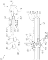
- figure 2 1 shows a coating system 10 as a second exemplary embodiment, in which there is a single color changing device, designated 48 there, with a connection block 50, which includes both docking units 58.1 and 58.2. Accordingly, the connection block 50 provides the connections 56.1 and 56.2 connected to the ring lines 54, the guide devices 62.1 and 62.2 and the coupling devices 64.1 and 64.2 for both docking units 58.1, 58.2.
- the connection block 50 provides the connections 56.1 and 56.2 connected to the ring lines 54, the guide devices 62.1 and 62.2 and the coupling devices 64.1 and 64.2 for both docking units 58.1, 58.2.
- not all components are provided with a reference number for the sake of simplicity.
- both docking units 58.1, 58.2 are arranged on the same side of the connection block 50.
- the docking units 58.1 and 58.2 can also be guided on different sides of the connection block 50, in particular on opposite sides.
- the coating system 10 now functions as follows, with only the processes of interest here being explained below without going into detail about supplementary and known processes which are necessary, for example, for cleaning line sections.
- a working configuration of the coating system 10 is assumed as the initial situation, in which the application device 12 is supplied with paint from the second piston metering device 22.2, in that its piston 36.2 is moved in the direction of the valve unit 40.2.
- the valve unit 40.2 blocks the supply line 42.2 and the outlet line 44.2 and opens the flow path to the distributor 28. This in turn connects the feed line 24.2 to the delivery line 18 of the application device 12, which applies the material from the second piston dispenser 22.2 to an object.
- the feed line 24.1 between the distributor 28 and the first piston dispenser 22.1 is cleaned and dry, so that an electrical insulation gap is formed there.
- the docking unit 58.1 of the first color change device 48.1 is now moved to the connection 56 of that ring line 52 that carries the paint material that is to be applied next. For example, this is the paint line 52a.
- the coupling connection 60.1 of the docking unit 58.1 is correspondingly coupled to the connection 56a of the first color changing device 48.1.
- valve assembly 76.1 is placed in a loading configuration in which the coupling port 60.1 is connected to the pressure chamber 74.1, wherein the Piston 72.1 is first moved forward, so that the pressure chamber 74.1 has the smallest possible volume.
- the piston 72.1 is now moved back, as a result of which the pressure chamber 74.1 is filled with material from the paint line 54a.
- valve arrangement 76.1 of the docking unit 58.1 is placed in a pressure-generating configuration, so that the pressure chamber 74.1 is connected to the feed line 42.1 and specifically to its first feed section 80.1.
- the piston 36.1 of the first piston dispenser 22.1 is pushed forward so that the working space 38.1 has the smallest possible volume.
- the piston 72.1 is now moved forward, as a result of which the paint is pressed into the feed line 42.1 and thereby into the first and the second feed section 80.1 and 82.1 with a feed pressure.
- the delivery pressure can be adjusted via the piston advance.
- the paint can be conveyed to the piston metering device 22.1 with a reproducible and, in particular, uniform pressure, without pressure fluctuations occurring, as can occur when the intrinsic pressure in the ring line system 52 is used to transfer a paint material to one of the piston metering devices 22.1 , 22.2 to promote.
- the pressure loss along the conveying path caused by the smaller cross section in the feed lines 42.1, 42.2 can also be effectively counteracted in this way.
- the paint is conveyed further to the piston metering device 22.1 by means of pig technology, as is known per se.
- the piston metering device 22.1 When the paint reaches the first piston dispenser 22.1, its piston 36.1 moves back so that the paint can flow through the valve unit 40.1 into its working space 38.1.
- the delivery pressure device 66.1 serves to set the inlet pressure for feeding the media into the feed line 42.1
- the volume of the pressure chamber 74.1 can be smaller than the volume of paint required for the application, which must be taken up by the piston dispenser 22.1.
- the filling of the piston metering device 22.1 takes place in a corresponding manner in two or more steps in batches, during which time the application with material from the second piston metering device 22.2 can continue.
- the application device 12 Before the next electrostatic application process can be initiated and the application device 12 can be set to high voltage potential, the application device 12 must first be freed from the material from the second piston dispenser 22.2 and cleaned, and at the same time the feed line 42.1 must be freed from conductive material and dried so that in the Supply line 42.1 an electrical insulation gap is established.
- the paint material is pressed back into the ring line 52a through the feed line 42.1.
- the paint material is first conveyed into the pressure cylinder 68.1, for which purpose the valve arrangement 76.1 connects the feed line 42.1 to its pressure chamber 74.1.
- the valve assembly 76.1 is set so that the pressure chamber 74.1 is connected to the port 56.1a.
- the paint material is then pressed with the aid of the piston 72.1 from the pressure chamber 74.1 against its own pressure into the ring line 54a.
- the docking unit 58.1 is decoupled from the connection 56a, moved to the connection 56e of the discharge line 54a and coupled to it, so that the rest of the material can be discharged from the line system.
- valve arrangement 76.1 can be connected to its own cleaning agent line and/or its own drain line, so that a cleaning process can be carried out for the pressure cylinder 68.1 that is independent of the color change device 48.1.
- the first supply line 26.1 is now ready for the application of the paint material from the piston dispenser 22.1, for which purpose the valve unit 40.1 blocks the supply line 42.1 and connects the piston dispenser 22.1 to the distributor 28, which opens the flow path to the discharge line 18.
- the piston 36.1 is moved in the direction of the valve unit 40.1 and the paint is applied.
- the second piston dispenser 22.2 of the second supply line 26.2 can now be filled with material in the manner explained above.
Landscapes
- Spray Control Apparatus (AREA)
- Coating Apparatus (AREA)
Claims (10)
- Dispositif de changement pour des milieux, en particulier pour des laques, comprenanta) plusieurs raccords (56.1, 56.2), dont chacun peut être relié à un réservoir (54) pour un milieu ;b) au moins une unité d'amarrage (58.1, 58.2), qui comprend un raccord d'accouplement (60.1, 60.2), complémentaire aux raccords (56.1, 56.2), qui peut être relié à une conduite d'alimentation (42.1, 42.2) pour un moyen d'application (12) d'un système de revêtement (10) ;c) un dispositif de positionnement (62.1, 64.1; 62.2, 64.2) par l'intermédiaire duquel l'unité d'amarrage (58.1, 58.2) peut se déplacer par rapport aux raccords (56.1, 56.2) ;d) un dispositif (66,1, 66.2) à pression de refoulement, par l'intermédiaire duquel la pression d'entrée, avec lequel un milieu est injecté dans la conduite d'alimentation (42.1, 42.2), peut être réglée et / ou soutenue, et / ou par l'intermédiaire duquel la pression de retour, avec laquelle un milieu est réinjecté depuis la conduite d'alimentation (42.1, 42.2) dans son réservoir (54), peut être réglée et/ou soutenue,
caractérisé en ce quee) par l'intermédiaire d'un ensemble de soupape (76.1, 76.2) le raccord d'accouplement (60.1, 60.2) peut être relié directement à la conduite d'alimentation (42.1, 42.2), de telle sorte que le milieu peut être passé devant le dispositif (66,1, 66.2) à pression de refoulement. - Dispositif de changement selon la revendication 1, caractérisé en ce que le dispositif (66,1, 66.2) à pression de refoulement est emporté par l'unité d'amarrage (58.1, 58.2).
- Dispositif de changement selon la revendication 1 ou 2, caractérisé en ce que le dispositif (66,1, 66.2) à pression de refoulement est un cylindre de pression (68.1, 68.2) avec une chambre de pression (74.1, 74.2), qui peut être reliée par l'intermédiaire d'un ensemble de soupape (76.1, 76.2) facultativement au raccord d'accouplement (60.1, 60.2) de la station d'amarrage (58.1, 58.2) ou à la conduite d'alimentation (42.1, 42.2).
- Dispositif de changement selon l'une quelconque des revendications 1 à 3, caractérisé en ce qu'au moins deux unités d'amarrage (58.1, 58.2) existent.
- Dispositif de changement selon la revendication 4, caractérisé en ce que deux raccords (56.1, 56.2) et deux unités d'amarrage (58.1, 58.2) existent pour chaque réservoir (54), dont la première unité d'amarrage (58.1) coopère avec un des raccords (56.1) pour chaque réservoir (54), et la seconde unité d'amarrage (58.2) coopère avec l'autre des raccords (56.2, 56.1) pour chaque réservoir (54).
- Système de revêtement pour le revêtement des objets, comprenanta) un dispositif d'application (12);b) un système d'alimentation (26) avec au moins une conduite d'alimentation (42.1, 42.2), par laquelle un milieu liquide peut être alimenté au dispositif d'application (12),
caractérisé en ce quec) le système d'alimentation (26) comporte au moins un dispositif de changement (48.1, 48.2) pour des milieux selon l'une quelconque des revendications 1 à 5. - Système de revêtement selon la revendication 6, caractérisé en ce qu'au moins une section (80.1, 82.1; 80.2, 82.2) de la conduite d'alimentation (42.1, 42.2) est raclée.
- Système de revêtement selon la revendication 6 ou 7, caractérisé en ce que la conduite d'alimentation (42.1, 42.2), à l'extrémité éloignée du dispositif de changement (48.1, 48.2), est reliée à un récipient de stockage (20.1, 20.2), à partir duquel le dispositif d'application (12) peut être alimenté.
- Système de revêtement selon la revendication 8, caractérisé en ce que le récipient de stockage (20.1, 20.2) est un doseur à piston (22.1, 22.2).
- Système de revêtement selon l'une quelconque des revendications 6 à 9, caractérisé en ce que le système d'alimentation (26) comporte un distributeur (28), par lequel le dispositif d'application (12) peut être alimenté à partir d'une première ligne d'alimentation (26.1) ou à partir d'une seconde ligne d'alimentation (26.2), dans lequel chaque ligne d'alimentation (26.1, 26.2) comporte une conduite d'alimentation (42.1, 42.2) séparée, et tous les autres composants selon les revendications 7 à 10 existent séparément sur la première ligne d'alimentation (26.1) et la seconde ligne d'alimentation (26.2).
Applications Claiming Priority (2)
| Application Number | Priority Date | Filing Date | Title |
|---|---|---|---|
| DE102015008845.9A DE102015008845A1 (de) | 2015-07-13 | 2015-07-13 | Wechseleinrichtung und Beschichtungssystem zum Beschichten von Gegenständen |
| PCT/EP2016/063584 WO2017008977A1 (fr) | 2015-07-13 | 2016-06-14 | Dispositif de changement et système de revêtement pour le revêtement d'objets |
Publications (2)
| Publication Number | Publication Date |
|---|---|
| EP3322540A1 EP3322540A1 (fr) | 2018-05-23 |
| EP3322540B1 true EP3322540B1 (fr) | 2022-08-31 |
Family
ID=56137307
Family Applications (1)
| Application Number | Title | Priority Date | Filing Date |
|---|---|---|---|
| EP16730331.2A Active EP3322540B1 (fr) | 2015-07-13 | 2016-06-14 | Dispositif de changement et système de revêtement pour le revêtement d'objets |
Country Status (5)
| Country | Link |
|---|---|
| US (1) | US20180193865A1 (fr) |
| EP (1) | EP3322540B1 (fr) |
| CN (1) | CN107847959A (fr) |
| DE (1) | DE102015008845A1 (fr) |
| WO (1) | WO2017008977A1 (fr) |
Family Cites Families (17)
| Publication number | Priority date | Publication date | Assignee | Title |
|---|---|---|---|---|
| DE2064238C3 (de) * | 1970-02-02 | 1979-07-12 | Champion Spark Plug Co., Toledo, Ohio (V.St.A.) | Mehrfarbenspruheinrichtung |
| JPH06129563A (ja) * | 1992-10-16 | 1994-05-10 | Toyota Motor Corp | 切替バルブ |
| DE19962220C2 (de) * | 1999-12-22 | 2002-01-24 | Fraunhofer Ges Forschung | Beschichtungsstoff-Wechselsystem und Beschichtungssystem für die automatisierte Beschichtungstechnik sowie Verfahren zum automatisierten Beschichten |
| DE10064065B4 (de) * | 1999-12-22 | 2006-07-27 | Dürr Systems GmbH | Beschichtungssystem für die automatisierte Beschichtungstechnik |
| FR2803776B1 (fr) * | 2000-01-14 | 2002-06-07 | Sames Sa | Installation de projection de produit de revetement |
| DE10059041C2 (de) * | 2000-11-28 | 2002-11-14 | Lactec Ges Fuer Moderne Lackte | Verfahren und Vorrichtung zum Fördern von elektrisch leitfähigen Lacken zwischen unterschiedlichen Spannungspotenzialen |
| DE20122759U1 (de) * | 2001-03-29 | 2007-08-23 | Dürr Systems GmbH | Farbwechselsystem für eine Beschichtungsanlage |
| DE10120077B4 (de) * | 2001-04-24 | 2006-07-27 | Dürr Systems GmbH | Beschichtungssystem für die automatisierte Beschichtungstechnik |
| AU2003302604A1 (en) * | 2002-11-27 | 2004-06-23 | Nordson Corporation | Manifold mounting arrangement for supplying coating material to an application device |
| EP1773507B1 (fr) * | 2004-06-03 | 2012-08-15 | Nordson Corporation | Changement de couleur pour un systeme d'application de revetement en poudre |
| DE102006022570A1 (de) * | 2006-05-15 | 2007-11-29 | Dürr Systems GmbH | Beschichtungseinrichtung und zugehöriges Betriebsverfahren |
| ES2399882T3 (es) * | 2007-12-28 | 2013-04-04 | Industra Industrieanlagen - Maschinen Und Teile Gmbh | Sistema cambiador de color de pintura y procedimiento para cambiar un color de pintura |
| US8567341B1 (en) * | 2008-03-31 | 2013-10-29 | Gema Switzerland Gmbh | Supply changing apparatus for powder coating systems |
| CN105377445B (zh) * | 2013-07-19 | 2018-03-27 | 固瑞克明尼苏达有限公司 | 多点密封件润滑系统 |
| DE102013013549A1 (de) * | 2013-08-13 | 2015-02-19 | Eisenmann Ag | Wechseleinrichtung für Beschichtungsmedien und Beschichtungssystem zum Beschichten von Gegenständen |
| DE102013018636A1 (de) * | 2013-11-06 | 2015-05-07 | Eisenmann Ag | Wechseleinrichtung für Beschichtungsmedien und Beschichtungssystem zum Beschichten von Gegenständen |
| CN203643193U (zh) * | 2013-12-13 | 2014-06-11 | 上海烟草集团有限责任公司 | 静电捕集管喷淋装置 |
-
2015
- 2015-07-13 DE DE102015008845.9A patent/DE102015008845A1/de not_active Ceased
-
2016
- 2016-06-14 WO PCT/EP2016/063584 patent/WO2017008977A1/fr not_active Ceased
- 2016-06-14 US US15/742,227 patent/US20180193865A1/en not_active Abandoned
- 2016-06-14 CN CN201680041207.0A patent/CN107847959A/zh active Pending
- 2016-06-14 EP EP16730331.2A patent/EP3322540B1/fr active Active
Also Published As
| Publication number | Publication date |
|---|---|
| DE102015008845A1 (de) | 2017-01-19 |
| WO2017008977A1 (fr) | 2017-01-19 |
| US20180193865A1 (en) | 2018-07-12 |
| CN107847959A (zh) | 2018-03-27 |
| EP3322540A1 (fr) | 2018-05-23 |
Similar Documents
| Publication | Publication Date | Title |
|---|---|---|
| EP1142649B1 (fr) | Procédé et appareil de revêtement | |
| EP2432695A1 (fr) | Station de remplissage mixte | |
| DE10157966A1 (de) | Verfahren und Versorgungssystem zur dosierten Materialversorgung einer Beschichtungsvorrichtung | |
| EP3171983B1 (fr) | Système de revêtement servant au revêtement d'objets | |
| DE10064065B4 (de) | Beschichtungssystem für die automatisierte Beschichtungstechnik | |
| DE10131562A1 (de) | Verfahren und System zur Versorgung einer Beschichtungsvorrichtung | |
| EP3313584B1 (fr) | Bloc changeur de poudre et système de distribution de poudre pourvu dudit bloc changeur de poudre | |
| EP1369183A2 (fr) | Méthode et système d'alimentation de peinture pour une installation de revêtement électrostatique | |
| DE10342643A1 (de) | Verfahren zum Betrieb einer Medien-Förderanlage | |
| EP4572893A1 (fr) | Dispositif d'alimentation en agent de revêtement et procédé de fonctionnement associé | |
| DE102015008845A1 (de) | Wechseleinrichtung und Beschichtungssystem zum Beschichten von Gegenständen | |
| EP3015174A1 (fr) | Systeme de revetement d'objets | |
| WO2019145339A1 (fr) | Centre d'alimentation en poudre à plusieurs couleurs pour l'alimentation en cas de besoin d'au moins un dispositif de pulvérisation de poudre avec une poudre de revêtement de différent types | |
| WO2019145355A1 (fr) | Centre d'alimentation en poudres multicolores conçu pour alimenter à la demande au moins un dispositif de pulvérisation de poudres en poudres de revêtement de différents types | |
| EP3899278B1 (fr) | Système de pompe | |
| EP3188844B1 (fr) | Système de revêtement permettant de revêtir des objets | |
| EP3012028B1 (fr) | Dispositif de dosage à piston pour milieux liquides pour l'enduction d'objets | |
| EP1584376B1 (fr) | Procédé de transport d'un materiau de revêtement et machine de revêtement | |
| EP3017873B1 (fr) | Systeme de revetement d'objets | |
| EP1502656B1 (fr) | Méthode et système d'alimentation de peinture pour une installation de revêtement électrostatique et système de liaison pour cela | |
| EP2581136A1 (fr) | Dispositif de transport pour liquides et installation de laquage | |
| WO2025119802A1 (fr) | Alimentation en agent de revêtement et procédé de fonctionnement associé | |
| EP4599816A1 (fr) | Dispositif de fabrication de pièces sérigraphiées tridimensionnelles | |
| WO2012113514A1 (fr) | Doseur à piston pour milieux fluides | |
| WO2019145365A1 (fr) | Centre d'alimentation en poudre multicolore destiné à alimenter selon les besoins au moins un équipement d'aspersion de poudre en poudre de revêtement de types différents |
Legal Events
| Date | Code | Title | Description |
|---|---|---|---|
| STAA | Information on the status of an ep patent application or granted ep patent |
Free format text: STATUS: THE INTERNATIONAL PUBLICATION HAS BEEN MADE |
|
| PUAI | Public reference made under article 153(3) epc to a published international application that has entered the european phase |
Free format text: ORIGINAL CODE: 0009012 |
|
| STAA | Information on the status of an ep patent application or granted ep patent |
Free format text: STATUS: REQUEST FOR EXAMINATION WAS MADE |
|
| 17P | Request for examination filed |
Effective date: 20171103 |
|
| AK | Designated contracting states |
Kind code of ref document: A1 Designated state(s): AL AT BE BG CH CY CZ DE DK EE ES FI FR GB GR HR HU IE IS IT LI LT LU LV MC MK MT NL NO PL PT RO RS SE SI SK SM TR |
|
| AX | Request for extension of the european patent |
Extension state: BA ME |
|
| DAV | Request for validation of the european patent (deleted) | ||
| DAX | Request for extension of the european patent (deleted) | ||
| 19U | Interruption of proceedings before grant |
Effective date: 20190731 |
|
| 19W | Proceedings resumed before grant after interruption of proceedings |
Effective date: 20200803 |
|
| STAA | Information on the status of an ep patent application or granted ep patent |
Free format text: STATUS: EXAMINATION IS IN PROGRESS |
|
| 17Q | First examination report despatched |
Effective date: 20200831 |
|
| GRAP | Despatch of communication of intention to grant a patent |
Free format text: ORIGINAL CODE: EPIDOSNIGR1 |
|
| STAA | Information on the status of an ep patent application or granted ep patent |
Free format text: STATUS: GRANT OF PATENT IS INTENDED |
|
| INTG | Intention to grant announced |
Effective date: 20220325 |
|
| GRAS | Grant fee paid |
Free format text: ORIGINAL CODE: EPIDOSNIGR3 |
|
| GRAA | (expected) grant |
Free format text: ORIGINAL CODE: 0009210 |
|
| STAA | Information on the status of an ep patent application or granted ep patent |
Free format text: STATUS: THE PATENT HAS BEEN GRANTED |
|
| AK | Designated contracting states |
Kind code of ref document: B1 Designated state(s): AL AT BE BG CH CY CZ DE DK EE ES FI FR GB GR HR HU IE IS IT LI LT LU LV MC MK MT NL NO PL PT RO RS SE SI SK SM TR |
|
| REG | Reference to a national code |
Ref country code: CH Ref legal event code: EP Ref country code: GB Ref legal event code: FG4D Free format text: NOT ENGLISH |
|
| REG | Reference to a national code |
Ref country code: AT Ref legal event code: REF Ref document number: 1514907 Country of ref document: AT Kind code of ref document: T Effective date: 20220915 Ref country code: DE Ref legal event code: R096 Ref document number: 502016015224 Country of ref document: DE |
|
| REG | Reference to a national code |
Ref country code: DE Ref legal event code: R081 Ref document number: 502016015224 Country of ref document: DE Owner name: B+M SURFACE SYSTEMS GMBH, DE Free format text: FORMER OWNER: EISENMANN ANLAGENBAU GMBH & CO. KG, 71032 BOEBLINGEN, DE |
|
| REG | Reference to a national code |
Ref country code: IE Ref legal event code: FG4D Free format text: LANGUAGE OF EP DOCUMENT: GERMAN |
|
| REG | Reference to a national code |
Ref country code: LT Ref legal event code: MG9D |
|
| REG | Reference to a national code |
Ref country code: NL Ref legal event code: MP Effective date: 20220831 |
|
| RAP2 | Party data changed (patent owner data changed or rights of a patent transferred) |
Owner name: B+M SURFACE SYSTEMS GMBH |
|
| PG25 | Lapsed in a contracting state [announced via postgrant information from national office to epo] |
Ref country code: SE Free format text: LAPSE BECAUSE OF FAILURE TO SUBMIT A TRANSLATION OF THE DESCRIPTION OR TO PAY THE FEE WITHIN THE PRESCRIBED TIME-LIMIT Effective date: 20220831 Ref country code: RS Free format text: LAPSE BECAUSE OF FAILURE TO SUBMIT A TRANSLATION OF THE DESCRIPTION OR TO PAY THE FEE WITHIN THE PRESCRIBED TIME-LIMIT Effective date: 20220831 Ref country code: NO Free format text: LAPSE BECAUSE OF FAILURE TO SUBMIT A TRANSLATION OF THE DESCRIPTION OR TO PAY THE FEE WITHIN THE PRESCRIBED TIME-LIMIT Effective date: 20221130 Ref country code: LV Free format text: LAPSE BECAUSE OF FAILURE TO SUBMIT A TRANSLATION OF THE DESCRIPTION OR TO PAY THE FEE WITHIN THE PRESCRIBED TIME-LIMIT Effective date: 20220831 Ref country code: LT Free format text: LAPSE BECAUSE OF FAILURE TO SUBMIT A TRANSLATION OF THE DESCRIPTION OR TO PAY THE FEE WITHIN THE PRESCRIBED TIME-LIMIT Effective date: 20220831 Ref country code: FI Free format text: LAPSE BECAUSE OF FAILURE TO SUBMIT A TRANSLATION OF THE DESCRIPTION OR TO PAY THE FEE WITHIN THE PRESCRIBED TIME-LIMIT Effective date: 20220831 |
|
| PG25 | Lapsed in a contracting state [announced via postgrant information from national office to epo] |
Ref country code: PL Free format text: LAPSE BECAUSE OF FAILURE TO SUBMIT A TRANSLATION OF THE DESCRIPTION OR TO PAY THE FEE WITHIN THE PRESCRIBED TIME-LIMIT Effective date: 20220831 Ref country code: IS Free format text: LAPSE BECAUSE OF FAILURE TO SUBMIT A TRANSLATION OF THE DESCRIPTION OR TO PAY THE FEE WITHIN THE PRESCRIBED TIME-LIMIT Effective date: 20221231 Ref country code: HR Free format text: LAPSE BECAUSE OF FAILURE TO SUBMIT A TRANSLATION OF THE DESCRIPTION OR TO PAY THE FEE WITHIN THE PRESCRIBED TIME-LIMIT Effective date: 20220831 Ref country code: GR Free format text: LAPSE BECAUSE OF FAILURE TO SUBMIT A TRANSLATION OF THE DESCRIPTION OR TO PAY THE FEE WITHIN THE PRESCRIBED TIME-LIMIT Effective date: 20221201 |
|
| REG | Reference to a national code |
Ref country code: DE Ref legal event code: R081 Ref document number: 502016015224 Country of ref document: DE Owner name: B+M SURFACE SYSTEMS GMBH, DE Free format text: FORMER OWNER: EISENMANN SE, 71032 BOEBLINGEN, DE |
|
| PG25 | Lapsed in a contracting state [announced via postgrant information from national office to epo] |
Ref country code: SM Free format text: LAPSE BECAUSE OF FAILURE TO SUBMIT A TRANSLATION OF THE DESCRIPTION OR TO PAY THE FEE WITHIN THE PRESCRIBED TIME-LIMIT Effective date: 20220831 Ref country code: RO Free format text: LAPSE BECAUSE OF FAILURE TO SUBMIT A TRANSLATION OF THE DESCRIPTION OR TO PAY THE FEE WITHIN THE PRESCRIBED TIME-LIMIT Effective date: 20220831 Ref country code: PT Free format text: LAPSE BECAUSE OF FAILURE TO SUBMIT A TRANSLATION OF THE DESCRIPTION OR TO PAY THE FEE WITHIN THE PRESCRIBED TIME-LIMIT Effective date: 20230102 Ref country code: ES Free format text: LAPSE BECAUSE OF FAILURE TO SUBMIT A TRANSLATION OF THE DESCRIPTION OR TO PAY THE FEE WITHIN THE PRESCRIBED TIME-LIMIT Effective date: 20220831 Ref country code: DK Free format text: LAPSE BECAUSE OF FAILURE TO SUBMIT A TRANSLATION OF THE DESCRIPTION OR TO PAY THE FEE WITHIN THE PRESCRIBED TIME-LIMIT Effective date: 20220831 Ref country code: CZ Free format text: LAPSE BECAUSE OF FAILURE TO SUBMIT A TRANSLATION OF THE DESCRIPTION OR TO PAY THE FEE WITHIN THE PRESCRIBED TIME-LIMIT Effective date: 20220831 |
|
| PG25 | Lapsed in a contracting state [announced via postgrant information from national office to epo] |
Ref country code: SK Free format text: LAPSE BECAUSE OF FAILURE TO SUBMIT A TRANSLATION OF THE DESCRIPTION OR TO PAY THE FEE WITHIN THE PRESCRIBED TIME-LIMIT Effective date: 20220831 Ref country code: EE Free format text: LAPSE BECAUSE OF FAILURE TO SUBMIT A TRANSLATION OF THE DESCRIPTION OR TO PAY THE FEE WITHIN THE PRESCRIBED TIME-LIMIT Effective date: 20220831 |
|
| REG | Reference to a national code |
Ref country code: DE Ref legal event code: R097 Ref document number: 502016015224 Country of ref document: DE |
|
| PG25 | Lapsed in a contracting state [announced via postgrant information from national office to epo] |
Ref country code: NL Free format text: LAPSE BECAUSE OF FAILURE TO SUBMIT A TRANSLATION OF THE DESCRIPTION OR TO PAY THE FEE WITHIN THE PRESCRIBED TIME-LIMIT Effective date: 20220831 Ref country code: AL Free format text: LAPSE BECAUSE OF FAILURE TO SUBMIT A TRANSLATION OF THE DESCRIPTION OR TO PAY THE FEE WITHIN THE PRESCRIBED TIME-LIMIT Effective date: 20220831 |
|
| PLBE | No opposition filed within time limit |
Free format text: ORIGINAL CODE: 0009261 |
|
| STAA | Information on the status of an ep patent application or granted ep patent |
Free format text: STATUS: NO OPPOSITION FILED WITHIN TIME LIMIT |
|
| 26N | No opposition filed |
Effective date: 20230601 |
|
| PG25 | Lapsed in a contracting state [announced via postgrant information from national office to epo] |
Ref country code: SI Free format text: LAPSE BECAUSE OF FAILURE TO SUBMIT A TRANSLATION OF THE DESCRIPTION OR TO PAY THE FEE WITHIN THE PRESCRIBED TIME-LIMIT Effective date: 20220831 |
|
| PG25 | Lapsed in a contracting state [announced via postgrant information from national office to epo] |
Ref country code: MC Free format text: LAPSE BECAUSE OF FAILURE TO SUBMIT A TRANSLATION OF THE DESCRIPTION OR TO PAY THE FEE WITHIN THE PRESCRIBED TIME-LIMIT Effective date: 20220831 |
|
| PG25 | Lapsed in a contracting state [announced via postgrant information from national office to epo] |
Ref country code: MC Free format text: LAPSE BECAUSE OF FAILURE TO SUBMIT A TRANSLATION OF THE DESCRIPTION OR TO PAY THE FEE WITHIN THE PRESCRIBED TIME-LIMIT Effective date: 20220831 |
|
| REG | Reference to a national code |
Ref country code: CH Ref legal event code: PL |
|
| REG | Reference to a national code |
Ref country code: BE Ref legal event code: MM Effective date: 20230630 |
|
| GBPC | Gb: european patent ceased through non-payment of renewal fee |
Effective date: 20230614 |
|
| PG25 | Lapsed in a contracting state [announced via postgrant information from national office to epo] |
Ref country code: LU Free format text: LAPSE BECAUSE OF NON-PAYMENT OF DUE FEES Effective date: 20230614 |
|
| REG | Reference to a national code |
Ref country code: IE Ref legal event code: MM4A |
|
| PG25 | Lapsed in a contracting state [announced via postgrant information from national office to epo] |
Ref country code: LU Free format text: LAPSE BECAUSE OF NON-PAYMENT OF DUE FEES Effective date: 20230614 |
|
| PG25 | Lapsed in a contracting state [announced via postgrant information from national office to epo] |
Ref country code: IE Free format text: LAPSE BECAUSE OF NON-PAYMENT OF DUE FEES Effective date: 20230614 |
|
| PG25 | Lapsed in a contracting state [announced via postgrant information from national office to epo] |
Ref country code: IE Free format text: LAPSE BECAUSE OF NON-PAYMENT OF DUE FEES Effective date: 20230614 Ref country code: GB Free format text: LAPSE BECAUSE OF NON-PAYMENT OF DUE FEES Effective date: 20230614 Ref country code: CH Free format text: LAPSE BECAUSE OF NON-PAYMENT OF DUE FEES Effective date: 20230630 |
|
| PG25 | Lapsed in a contracting state [announced via postgrant information from national office to epo] |
Ref country code: IT Free format text: LAPSE BECAUSE OF FAILURE TO SUBMIT A TRANSLATION OF THE DESCRIPTION OR TO PAY THE FEE WITHIN THE PRESCRIBED TIME-LIMIT Effective date: 20220831 Ref country code: FR Free format text: LAPSE BECAUSE OF NON-PAYMENT OF DUE FEES Effective date: 20230630 Ref country code: BE Free format text: LAPSE BECAUSE OF NON-PAYMENT OF DUE FEES Effective date: 20230630 |
|
| PGFP | Annual fee paid to national office [announced via postgrant information from national office to epo] |
Ref country code: DE Payment date: 20240621 Year of fee payment: 9 |
|
| REG | Reference to a national code |
Ref country code: AT Ref legal event code: MM01 Ref document number: 1514907 Country of ref document: AT Kind code of ref document: T Effective date: 20230614 |
|
| PG25 | Lapsed in a contracting state [announced via postgrant information from national office to epo] |
Ref country code: AT Free format text: LAPSE BECAUSE OF NON-PAYMENT OF DUE FEES Effective date: 20230614 |
|
| PG25 | Lapsed in a contracting state [announced via postgrant information from national office to epo] |
Ref country code: AT Free format text: LAPSE BECAUSE OF NON-PAYMENT OF DUE FEES Effective date: 20230614 |
|
| PG25 | Lapsed in a contracting state [announced via postgrant information from national office to epo] |
Ref country code: BG Free format text: LAPSE BECAUSE OF FAILURE TO SUBMIT A TRANSLATION OF THE DESCRIPTION OR TO PAY THE FEE WITHIN THE PRESCRIBED TIME-LIMIT Effective date: 20220831 |
|
| PG25 | Lapsed in a contracting state [announced via postgrant information from national office to epo] |
Ref country code: BG Free format text: LAPSE BECAUSE OF FAILURE TO SUBMIT A TRANSLATION OF THE DESCRIPTION OR TO PAY THE FEE WITHIN THE PRESCRIBED TIME-LIMIT Effective date: 20220831 |
|
| PG25 | Lapsed in a contracting state [announced via postgrant information from national office to epo] |
Ref country code: CY Free format text: LAPSE BECAUSE OF FAILURE TO SUBMIT A TRANSLATION OF THE DESCRIPTION OR TO PAY THE FEE WITHIN THE PRESCRIBED TIME-LIMIT; INVALID AB INITIO Effective date: 20160614 |
|
| PG25 | Lapsed in a contracting state [announced via postgrant information from national office to epo] |
Ref country code: HU Free format text: LAPSE BECAUSE OF FAILURE TO SUBMIT A TRANSLATION OF THE DESCRIPTION OR TO PAY THE FEE WITHIN THE PRESCRIBED TIME-LIMIT; INVALID AB INITIO Effective date: 20160614 |
|
| PG25 | Lapsed in a contracting state [announced via postgrant information from national office to epo] |
Ref country code: TR Free format text: LAPSE BECAUSE OF FAILURE TO SUBMIT A TRANSLATION OF THE DESCRIPTION OR TO PAY THE FEE WITHIN THE PRESCRIBED TIME-LIMIT Effective date: 20220831 |
|
| REG | Reference to a national code |
Ref country code: DE Ref legal event code: R119 Ref document number: 502016015224 Country of ref document: DE |
|
| PG25 | Lapsed in a contracting state [announced via postgrant information from national office to epo] |
Ref country code: DE Free format text: LAPSE BECAUSE OF NON-PAYMENT OF DUE FEES Effective date: 20260101 |