EP3322554B1 - Procédé pour la fabrication additive de pièces métalliques - Google Patents
Procédé pour la fabrication additive de pièces métalliques Download PDFInfo
- Publication number
- EP3322554B1 EP3322554B1 EP16735857.1A EP16735857A EP3322554B1 EP 3322554 B1 EP3322554 B1 EP 3322554B1 EP 16735857 A EP16735857 A EP 16735857A EP 3322554 B1 EP3322554 B1 EP 3322554B1
- Authority
- EP
- European Patent Office
- Prior art keywords
- wire
- workpiece
- vacuum chamber
- component
- metallic material
- Prior art date
- Legal status (The legal status is an assumption and is not a legal conclusion. Google has not performed a legal analysis and makes no representation as to the accuracy of the status listed.)
- Active
Links
Images
Classifications
-
- B—PERFORMING OPERATIONS; TRANSPORTING
- B23—MACHINE TOOLS; METAL-WORKING NOT OTHERWISE PROVIDED FOR
- B23K—SOLDERING OR UNSOLDERING; WELDING; CLADDING OR PLATING BY SOLDERING OR WELDING; CUTTING BY APPLYING HEAT LOCALLY, e.g. FLAME CUTTING; WORKING BY LASER BEAM
- B23K15/00—Electron-beam welding or cutting
- B23K15/002—Devices involving relative movement between electron beam and workpiece
-
- B—PERFORMING OPERATIONS; TRANSPORTING
- B22—CASTING; POWDER METALLURGY
- B22F—WORKING METALLIC POWDER; MANUFACTURE OF ARTICLES FROM METALLIC POWDER; MAKING METALLIC POWDER; APPARATUS OR DEVICES SPECIALLY ADAPTED FOR METALLIC POWDER
- B22F10/00—Additive manufacturing of workpieces or articles from metallic powder
- B22F10/20—Direct sintering or melting
- B22F10/25—Direct deposition of metal particles, e.g. direct metal deposition [DMD] or laser engineered net shaping [LENS]
-
- B—PERFORMING OPERATIONS; TRANSPORTING
- B22—CASTING; POWDER METALLURGY
- B22F—WORKING METALLIC POWDER; MANUFACTURE OF ARTICLES FROM METALLIC POWDER; MAKING METALLIC POWDER; APPARATUS OR DEVICES SPECIALLY ADAPTED FOR METALLIC POWDER
- B22F12/00—Apparatus or devices specially adapted for additive manufacturing; Auxiliary means for additive manufacturing; Combinations of additive manufacturing apparatus or devices with other processing apparatus or devices
- B22F12/10—Auxiliary heating means
- B22F12/13—Auxiliary heating means to preheat the material
-
- B—PERFORMING OPERATIONS; TRANSPORTING
- B23—MACHINE TOOLS; METAL-WORKING NOT OTHERWISE PROVIDED FOR
- B23K—SOLDERING OR UNSOLDERING; WELDING; CLADDING OR PLATING BY SOLDERING OR WELDING; CUTTING BY APPLYING HEAT LOCALLY, e.g. FLAME CUTTING; WORKING BY LASER BEAM
- B23K15/00—Electron-beam welding or cutting
- B23K15/0046—Welding
- B23K15/0086—Welding welding for purposes other than joining, e.g. build-up welding
-
- B—PERFORMING OPERATIONS; TRANSPORTING
- B23—MACHINE TOOLS; METAL-WORKING NOT OTHERWISE PROVIDED FOR
- B23K—SOLDERING OR UNSOLDERING; WELDING; CLADDING OR PLATING BY SOLDERING OR WELDING; CUTTING BY APPLYING HEAT LOCALLY, e.g. FLAME CUTTING; WORKING BY LASER BEAM
- B23K15/00—Electron-beam welding or cutting
- B23K15/06—Electron-beam welding or cutting within a vacuum chamber
-
- B—PERFORMING OPERATIONS; TRANSPORTING
- B23—MACHINE TOOLS; METAL-WORKING NOT OTHERWISE PROVIDED FOR
- B23K—SOLDERING OR UNSOLDERING; WELDING; CLADDING OR PLATING BY SOLDERING OR WELDING; CUTTING BY APPLYING HEAT LOCALLY, e.g. FLAME CUTTING; WORKING BY LASER BEAM
- B23K26/00—Working by laser beam, e.g. welding, cutting or boring
- B23K26/08—Devices involving relative movement between laser beam and workpiece
- B23K26/083—Devices involving movement of the workpiece in at least one axial direction
- B23K26/0853—Devices involving movement of the workpiece in at least two axial directions, e.g. in a plane
- B23K26/0861—Devices involving movement of the workpiece in at least two axial directions, e.g. in a plane in at least three axial directions
-
- B—PERFORMING OPERATIONS; TRANSPORTING
- B23—MACHINE TOOLS; METAL-WORKING NOT OTHERWISE PROVIDED FOR
- B23K—SOLDERING OR UNSOLDERING; WELDING; CLADDING OR PLATING BY SOLDERING OR WELDING; CUTTING BY APPLYING HEAT LOCALLY, e.g. FLAME CUTTING; WORKING BY LASER BEAM
- B23K26/00—Working by laser beam, e.g. welding, cutting or boring
- B23K26/12—Working by laser beam, e.g. welding, cutting or boring in a special environment or atmosphere, e.g. in an enclosure
- B23K26/1224—Working by laser beam, e.g. welding, cutting or boring in a special environment or atmosphere, e.g. in an enclosure in vacuum
-
- B—PERFORMING OPERATIONS; TRANSPORTING
- B23—MACHINE TOOLS; METAL-WORKING NOT OTHERWISE PROVIDED FOR
- B23K—SOLDERING OR UNSOLDERING; WELDING; CLADDING OR PLATING BY SOLDERING OR WELDING; CUTTING BY APPLYING HEAT LOCALLY, e.g. FLAME CUTTING; WORKING BY LASER BEAM
- B23K26/00—Working by laser beam, e.g. welding, cutting or boring
- B23K26/12—Working by laser beam, e.g. welding, cutting or boring in a special environment or atmosphere, e.g. in an enclosure
- B23K26/127—Working by laser beam, e.g. welding, cutting or boring in a special environment or atmosphere, e.g. in an enclosure in an enclosure
-
- B—PERFORMING OPERATIONS; TRANSPORTING
- B23—MACHINE TOOLS; METAL-WORKING NOT OTHERWISE PROVIDED FOR
- B23K—SOLDERING OR UNSOLDERING; WELDING; CLADDING OR PLATING BY SOLDERING OR WELDING; CUTTING BY APPLYING HEAT LOCALLY, e.g. FLAME CUTTING; WORKING BY LASER BEAM
- B23K26/00—Working by laser beam, e.g. welding, cutting or boring
- B23K26/34—Laser welding for purposes other than joining
-
- B—PERFORMING OPERATIONS; TRANSPORTING
- B23—MACHINE TOOLS; METAL-WORKING NOT OTHERWISE PROVIDED FOR
- B23K—SOLDERING OR UNSOLDERING; WELDING; CLADDING OR PLATING BY SOLDERING OR WELDING; CUTTING BY APPLYING HEAT LOCALLY, e.g. FLAME CUTTING; WORKING BY LASER BEAM
- B23K26/00—Working by laser beam, e.g. welding, cutting or boring
- B23K26/34—Laser welding for purposes other than joining
- B23K26/342—Build-up welding
-
- B—PERFORMING OPERATIONS; TRANSPORTING
- B23—MACHINE TOOLS; METAL-WORKING NOT OTHERWISE PROVIDED FOR
- B23K—SOLDERING OR UNSOLDERING; WELDING; CLADDING OR PLATING BY SOLDERING OR WELDING; CUTTING BY APPLYING HEAT LOCALLY, e.g. FLAME CUTTING; WORKING BY LASER BEAM
- B23K26/00—Working by laser beam, e.g. welding, cutting or boring
- B23K26/352—Working by laser beam, e.g. welding, cutting or boring for surface treatment
- B23K26/354—Working by laser beam, e.g. welding, cutting or boring for surface treatment by melting
-
- B—PERFORMING OPERATIONS; TRANSPORTING
- B33—ADDITIVE MANUFACTURING TECHNOLOGY
- B33Y—ADDITIVE MANUFACTURING, i.e. MANUFACTURING OF THREE-DIMENSIONAL [3D] OBJECTS BY ADDITIVE DEPOSITION, ADDITIVE AGGLOMERATION OR ADDITIVE LAYERING, e.g. BY 3D PRINTING, STEREOLITHOGRAPHY OR SELECTIVE LASER SINTERING
- B33Y10/00—Processes of additive manufacturing
-
- B—PERFORMING OPERATIONS; TRANSPORTING
- B33—ADDITIVE MANUFACTURING TECHNOLOGY
- B33Y—ADDITIVE MANUFACTURING, i.e. MANUFACTURING OF THREE-DIMENSIONAL [3D] OBJECTS BY ADDITIVE DEPOSITION, ADDITIVE AGGLOMERATION OR ADDITIVE LAYERING, e.g. BY 3D PRINTING, STEREOLITHOGRAPHY OR SELECTIVE LASER SINTERING
- B33Y40/00—Auxiliary operations or equipment, e.g. for material handling
-
- B—PERFORMING OPERATIONS; TRANSPORTING
- B33—ADDITIVE MANUFACTURING TECHNOLOGY
- B33Y—ADDITIVE MANUFACTURING, i.e. MANUFACTURING OF THREE-DIMENSIONAL [3D] OBJECTS BY ADDITIVE DEPOSITION, ADDITIVE AGGLOMERATION OR ADDITIVE LAYERING, e.g. BY 3D PRINTING, STEREOLITHOGRAPHY OR SELECTIVE LASER SINTERING
- B33Y40/00—Auxiliary operations or equipment, e.g. for material handling
- B33Y40/10—Pre-treatment
-
- B—PERFORMING OPERATIONS; TRANSPORTING
- B22—CASTING; POWDER METALLURGY
- B22F—WORKING METALLIC POWDER; MANUFACTURE OF ARTICLES FROM METALLIC POWDER; MAKING METALLIC POWDER; APPARATUS OR DEVICES SPECIALLY ADAPTED FOR METALLIC POWDER
- B22F10/00—Additive manufacturing of workpieces or articles from metallic powder
- B22F10/30—Process control
- B22F10/32—Process control of the atmosphere, e.g. composition or pressure in a building chamber
-
- B—PERFORMING OPERATIONS; TRANSPORTING
- B22—CASTING; POWDER METALLURGY
- B22F—WORKING METALLIC POWDER; MANUFACTURE OF ARTICLES FROM METALLIC POWDER; MAKING METALLIC POWDER; APPARATUS OR DEVICES SPECIALLY ADAPTED FOR METALLIC POWDER
- B22F2999/00—Aspects linked to processes or compositions used in powder metallurgy
-
- Y—GENERAL TAGGING OF NEW TECHNOLOGICAL DEVELOPMENTS; GENERAL TAGGING OF CROSS-SECTIONAL TECHNOLOGIES SPANNING OVER SEVERAL SECTIONS OF THE IPC; TECHNICAL SUBJECTS COVERED BY FORMER USPC CROSS-REFERENCE ART COLLECTIONS [XRACs] AND DIGESTS
- Y02—TECHNOLOGIES OR APPLICATIONS FOR MITIGATION OR ADAPTATION AGAINST CLIMATE CHANGE
- Y02P—CLIMATE CHANGE MITIGATION TECHNOLOGIES IN THE PRODUCTION OR PROCESSING OF GOODS
- Y02P10/00—Technologies related to metal processing
- Y02P10/25—Process efficiency
Definitions
- the present invention relates to a method for the additive production of three-dimensional, metallic components, the components being built up in layers or sections under vacuum conditions by fusing a metallic material with the component at a processing point using a radiation source with high energy density, the metallic material is fed as wire, the wire being preheated under vacuum conditions prior to reaching the processing site.
- Such methods are, for example, from EP 1 296 788 B1 or the DE 10 2013 108 111 A1 known.
- a powder layer is first applied to the sections of the workpiece that have already been produced, with the powder layer then with the help of a suitable radiation source, such as. B. a laser or an electron beam gun is fused with the substrate at the points at which a material application is desired. This process is repeated until the desired component is produced, with complex three-dimensional structures being possible due to the layered construction, which cannot be produced with conventional production methods or can only be produced with great effort.
- US2005/0173380 A1 describes a process for the additive manufacturing of components made of wire. Another additive manufacturing process is US 6,751,516 B1 known.
- Another problem can be that to apply the respective layer, a relatively high amount of energy has to be supplied by the laser or electron beam, which occasionally leads to an undesirably deep melting of the material layers already produced, which can impair the quality of the component to be produced .
- Feeding in wire is already known from the field of welding technology. However, it has been shown that the problem discussed above of the high heat input occurs precisely when wire is fed. Such a non-additive method is from U.S. 2002/0117485 A1 and the US 2011/0297658 A1 known.
- a method of the type mentioned is from US 2010/270274 A known, which serves as a basis for the preamble of claim 1. There, an electron beam is used for the energy input, which is also used to preheat the wire.
- the object of the present invention is to create a method of the type mentioned at the beginning that can be carried out with a relatively low energy input due to the radiation at the processing point.
- the object is achieved by a method of the type described above, in which the melting energy is applied by a laser beam, the wire being directly electrically preheated by means of resistance heating or inductively.
- the thermal energy is introduced into the wire within the vacuum conditions by preheating the wire inductively or electrically.
- inductive preheating an alternating magnetic field is built up by means of a coil that surrounds the fed wire, which produces eddy currents in the wire, which lead to heating of the wire.
- the alternatively possible direct electrical preheating is preferably technically implemented in that the current for heating the wire is conducted via the wire on the one hand and the workpiece on the other hand from which the component is made. This is made possible by the contact of the wire with the weld pool.
- the wire is heated with direct current with a negative polarity applied to the wire and a positive polarity applied to the workpiece.
- the method can be carried out more precisely overall and with a lower heat input into the workpiece material, in particular below the machining point. Because the wire is already preheated to provide a significant amount of energy in the form of heat until the melting point is reached, the radiant energy of the laser beam can be smaller, so that a melt pool generated at the processing point penetrates less deeply into the already applied layers of the component.
- the radiation source can also be made smaller if necessary.
- the wire feed also makes it possible to feed the metallic material exactly in the required quantity, so that less residual material that has to be disposed of occurs within the vacuum conditions that are usually generated within a closed vacuum chamber.
- a further advantage of the method according to the invention is that it can be carried out continuously at least in certain areas, for example by traversing the surface of the workpiece line by line with the processing point.
- the machining point moves relative to the workpiece by moving the workpiece relative to the machining point, which is stationary.
- the wire is fed through a vacuum feedthrough into the vacuum chamber already mentioned, in which the component is produced step by step through the construction of the workpiece.
- the wire is fed into the chamber preheated.
- This measure can be desirable if the heat output of the inductive or direct electrical heating device arranged in the chamber is to be kept as small as possible.
- the temperature of the wire cannot be chosen to be arbitrarily large before it is fed into the vacuum chamber, so that this measure can only be used as a supplement.
- the laser beam is preferably introduced into the vacuum chamber through a window, so that the essential components of the laser can be arranged outside the vacuum chamber.
- the window is preferably provided with a gas purge in order to prevent metal vapors from condensing on the usually relatively cool inner surface of the window and from being able to clog the window over time.
- the gas flushing is usually carried out with an inert gas and is adjusted in such a way that the vacuum conditions are not disturbed.
- the wire is heated as much as possible by means of the preheating, without the quality of the material application on the workpiece for the production of the component being impaired by excessive heating.
- This means that the temperature of the wire can be increased to near or even above the solidus temperature of the metallic material without losing control of the material deposition. Rather, the energy of the laser beam can be reduced to such an extent that a particularly precise application on the workpiece is made possible.
- the feed rate of the wire depends of course on the desired amount of material at the point being processed and can also be completely interrupted, for example, if no material is to be deposited at certain points on the workpiece.
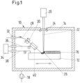
- In 1 1 shows a device 10 with which a method for additively manufacturing a metal component 12 in a vacuum chamber 14 can be carried out.
- the component 12, which is 1 is still shown as a workpiece in an intermediate stage, is mounted on a table, not shown in detail, which allows the component to be moved in the X, Y and Z directions.
- the component 12 is produced in layers in the sense of additive manufacturing, ie in the 1 In the exemplary embodiment shown, a number of layers have already been applied, with the current material layer 16 applied not being shown exaggerated to scale for the sake of illustration.
- the first layer can be built up on a substrate previously placed in the chamber 14 .
- a vacuum pump 18 evacuates the interior of the vacuum chamber 14 to the pressure values customary in the field of thermal vacuum machining processes.
- the energy input required to fuse supplied metallic material in the applied material layer 16 is provided by a laser 20 which is arranged outside of the vacuum chamber 14 .
- the laser beam 22 is guided through an entry window 24 in the wall of the vacuum chamber 14 to a processing point on the component 12, at which point a melt pool 26 is formed due to the high light output of the laser 20. Ventilation of the inside of the entry window 24 (not shown in detail) prevents metal vapors from condensing there as condensate.
- the metallic material is fed as wire 28 to the processing point on the molten bath 26 by means of a wire feed 30 shown in very simplified form.
- the wire 28 is fed through a vacuum passage 32 in the wall of the vacuum chamber 14 into the interior of the vacuum chamber and, for example, fed by driven friction rollers.
- the wire 28, which can possibly already be preheated outside of the vacuum chamber 14, is further heated by resistance heating so that it reaches a temperature in the region of the solidus point of the metallic material before it reaches the processing point.
- a power source 34 is provided outside the vacuum chamber to form a resistance heater, which is connected via electrical connection lines 36, 38, which are routed through the wall of the vacuum chamber 14 in a pressure-tight manner, to the workpiece 12 on the one hand and to the wire via an electrical contactor 40 on the other 28 connected.
- a direct current is used for heating, the negative polarity being connected to the electrical contactor 40 and the positive polarity being connected to the workpiece 12 .
- the electrical connections are dimensioned such that the resistance of the supplied wire 28 occurs between the electrical contactor 40 and the molten pool 26 on the workpiece surface for heating the wire to the desired temperature.
- the light output of the laser 20 can be set considerably lower than would be necessary without electrical preheating of the wire 28.
- This has the advantage that the molten bath 26 extends less deeply into the workpiece, so that previously applied layers on the workpiece 12 are less severely affected by the application of the further layer.
- the laser can also 20 are made smaller, which has a positive effect on the overall cost of the device 10.
- the wire While the wire is being fed in under the action of the electrical heating and the laser beam, the wire is melted in the molten bath 26 and applied to the workpiece 12 as a material layer 16 . Meanwhile, the component 12 is moved in a processing direction, resulting in a line-by-line structure. In principle, it is also possible to move in several coordinate directions at the same time, but usually a line-by-line structure of the material is desired. If a continuous formation of the material layer is not desired at a certain point because there should be no material on the finished component due to the design, the wire feed is interrupted, the laser beam is switched off and/or the traversing speed of the component 12 in these areas is increased significantly for a short time.
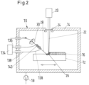
- a further device 10 is shown which, in most of the constructional details of FIG 1 corresponds to the device 10 shown and has therefore been provided with essentially the same reference numerals.
- induction heating is provided, in which a power source 134 arranged outside the vacuum chamber is connected via electrical supply lines 136, 138 via vacuum-tight bushings to an induction coil 140, which surrounds the wire between the wire feed 30 and the molten bath 26.
Landscapes
- Engineering & Computer Science (AREA)
- Mechanical Engineering (AREA)
- Physics & Mathematics (AREA)
- Optics & Photonics (AREA)
- Plasma & Fusion (AREA)
- Chemical & Material Sciences (AREA)
- Manufacturing & Machinery (AREA)
- Materials Engineering (AREA)
- Laser Beam Processing (AREA)
Claims (9)
- Procédé de fabrication additive de composants métalliques tridimensionnels (12), dans lequel les composants (12) sont réalisés sous forme de couches ou de segments, sous vide, par fusion d'une matière métallique avec le composant (12) en un point d'usinage au moyen d'une source de rayonnement présentant une densité d'énergie élevée, dans lequel le matériau métallique est acheminé sous la forme d'un fil (28), dans lequel le fil est préchauffé dans des conditions de vide avant d'atteindre le point d'usinage, caractérisé en ce que l'énergie de fusion est appliquée par un faisceau laser (2), dans lequel le fil est directement préchauffé électriquement au moyen d'un chauffage par résistance ou par induction.
- Procédé selon la revendication 1, caractérisé en ce que le courant pour chauffer le fil (28) passe par le fil (28) et la pièce à usiner.
- Procédé selon la revendication 2, caractérisé en ce que le fil est chauffé avec un courant continu, dans lequel une polarité négative est appliquée au fil (28) et une polarité positive est appliquée à la pièce à usiner.
- Procédé selon l'une quelconque des revendications précédentes, caractérisé en ce que le fil (28) est acheminé à travers un passage sous vide (32) dans une chambre sous vide (14) dans laquelle le composant (12) est fabriqué de manière additive.
- Procédé selon la revendication 4, caractérisé en ce que le fil (28) est acheminé dans la chambre sous vide (14) préchauffé.
- Procédé selon l'une quelconque des revendications précédentes, caractérisé en ce que le faisceau laser (22) est introduit dans la chambre sous vide (14) à travers une fenêtre (24).
- Procédé selon la revendication 6, caractérisé en ce que la fenêtre est rincée avec un gaz.
- Procédé selon l'une quelconque des revendications précédentes, caractérisé en ce que la pièce à usiner est déplacée par rapport au point d'usinage, qui est conçu pour être fixe.
- Procédé selon l'une quelconque des revendications précédentes, caractérisé en ce que le fil (28) est porté à une température qui est comprise entre une température légèrement inférieure ou légèrement supérieure à la température de solidus du matériau métallique.
Applications Claiming Priority (2)
| Application Number | Priority Date | Filing Date | Title |
|---|---|---|---|
| DE102015008919.6A DE102015008919A1 (de) | 2015-07-15 | 2015-07-15 | Verfahren zur additiven Herstellung von metallischen Bauteilen |
| PCT/EP2016/065757 WO2017009094A1 (fr) | 2015-07-15 | 2016-07-05 | Procédé pour la fabrication additive de pièces métalliques |
Publications (3)
| Publication Number | Publication Date |
|---|---|
| EP3322554A1 EP3322554A1 (fr) | 2018-05-23 |
| EP3322554B1 true EP3322554B1 (fr) | 2023-06-07 |
| EP3322554C0 EP3322554C0 (fr) | 2023-06-07 |
Family
ID=56363837
Family Applications (1)
| Application Number | Title | Priority Date | Filing Date |
|---|---|---|---|
| EP16735857.1A Active EP3322554B1 (fr) | 2015-07-15 | 2016-07-05 | Procédé pour la fabrication additive de pièces métalliques |
Country Status (4)
| Country | Link |
|---|---|
| US (1) | US10882139B2 (fr) |
| EP (1) | EP3322554B1 (fr) |
| DE (1) | DE102015008919A1 (fr) |
| WO (1) | WO2017009094A1 (fr) |
Families Citing this family (13)
| Publication number | Priority date | Publication date | Assignee | Title |
|---|---|---|---|---|
| DE102015008921A1 (de) * | 2015-07-15 | 2017-01-19 | Evobeam GmbH | Verfahren zur additiven Herstellung von Bauteilen |
| WO2019074827A1 (fr) * | 2017-10-09 | 2019-04-18 | Sciaky, Inc. | Système de fabrication additive par faisceau d'électrons et composants de commande |
| CN111386186A (zh) * | 2017-11-26 | 2020-07-07 | D.施华洛世奇两合公司 | 改善层的透明度、平滑度和粘合性的3d打印部件的热处理 |
| HU231144B1 (hu) | 2018-06-12 | 2021-03-01 | Al Bohacen Kft | Eljárás és berendezés 3-dimenziós fémtárgy, különösen 3-dimenziós tömör fémtárgy elõállítására |
| CA3101061A1 (fr) | 2018-06-20 | 2019-12-26 | Digital Alloys Incorporated | Devidoir multi-diametre |
| US11426818B2 (en) | 2018-08-10 | 2022-08-30 | The Research Foundation for the State University | Additive manufacturing processes and additively manufactured products |
| CN109514068B (zh) * | 2018-10-31 | 2022-01-14 | 南京理工大学 | 基于电子束热丝熔丝增材制造的装置 |
| CN109434286A (zh) * | 2018-12-21 | 2019-03-08 | 陕西天元智能再制造股份有限公司 | 一种高效率的丝材激光熔覆方法 |
| DE102019107887A1 (de) * | 2019-03-27 | 2020-10-01 | Fachhochschule Aachen | Verfahren zum Laser-Verschweißen mit einer mobilen Unterdruckkammer und Unterdruckkammer dafür |
| FR3095973B1 (fr) * | 2019-05-16 | 2021-05-07 | Safran Aircraft Engines | Procédé de de fabrication additive pour une pièce métallique |
| CN111730172A (zh) * | 2020-06-19 | 2020-10-02 | 南京理工大学 | 面向电弧增材制造的基板-丝材协同预热装置及方法 |
| CN112620656A (zh) * | 2021-01-12 | 2021-04-09 | 无锡科技职业学院 | 一种新型金属丝熔融沉积的加工机构与工艺 |
| CN119609328A (zh) * | 2024-12-16 | 2025-03-14 | 哈尔滨工业大学 | 一种焊接散热工装及焊接方法 |
Citations (1)
| Publication number | Priority date | Publication date | Assignee | Title |
|---|---|---|---|---|
| US20100270274A1 (en) * | 2009-04-28 | 2010-10-28 | Usa As Represented By The Administrator Of The National Aeronautics And Space Administration | Use of Beam Deflection to Control an Electron Beam Wire Deposition Process |
Family Cites Families (10)
| Publication number | Priority date | Publication date | Assignee | Title |
|---|---|---|---|---|
| BE784250A (fr) * | 1972-05-31 | 1972-09-18 | Cockerill | Dispositif de chauffage d'un produit metallique de grande longueur et de faible epaisseur. |
| US6521861B2 (en) * | 2000-02-07 | 2003-02-18 | General Electric Company | Method and apparatus for increasing welding rate for high aspect ratio welds |
| SE521124C2 (sv) | 2000-04-27 | 2003-09-30 | Arcam Ab | Anordning samt metod för framställande av en tredimensionell produkt |
| US6751516B1 (en) * | 2000-08-10 | 2004-06-15 | Richardson Technologies, Inc. | Method and system for direct writing, editing and transmitting a three dimensional part and imaging systems therefor |
| US7168935B1 (en) * | 2002-08-02 | 2007-01-30 | The United States Of America As Represented By The Administrator Of The National Aeronautics And Space Administration | Solid freeform fabrication apparatus and methods |
| US20050173380A1 (en) * | 2004-02-09 | 2005-08-11 | Carbone Frank L. | Directed energy net shape method and apparatus |
| US20050181228A1 (en) * | 2004-02-13 | 2005-08-18 | 3M Innovative Properties Company | Metal-cladded metal matrix composite wire |
| US20080105659A1 (en) * | 2006-11-02 | 2008-05-08 | General Electric Company | High temperature electron beam welding |
| US10086461B2 (en) * | 2009-01-13 | 2018-10-02 | Lincoln Global, Inc. | Method and system to start and use combination filler wire feed and high intensity energy source for welding |
| GB201213940D0 (en) | 2012-08-06 | 2012-09-19 | Materials Solutions | Additive manufacturing |
-
2015
- 2015-07-15 DE DE102015008919.6A patent/DE102015008919A1/de not_active Withdrawn
-
2016
- 2016-07-05 US US15/736,795 patent/US10882139B2/en active Active
- 2016-07-05 WO PCT/EP2016/065757 patent/WO2017009094A1/fr not_active Ceased
- 2016-07-05 EP EP16735857.1A patent/EP3322554B1/fr active Active
Patent Citations (1)
| Publication number | Priority date | Publication date | Assignee | Title |
|---|---|---|---|---|
| US20100270274A1 (en) * | 2009-04-28 | 2010-10-28 | Usa As Represented By The Administrator Of The National Aeronautics And Space Administration | Use of Beam Deflection to Control an Electron Beam Wire Deposition Process |
Also Published As
| Publication number | Publication date |
|---|---|
| EP3322554A1 (fr) | 2018-05-23 |
| US10882139B2 (en) | 2021-01-05 |
| EP3322554C0 (fr) | 2023-06-07 |
| DE102015008919A1 (de) | 2017-01-19 |
| WO2017009094A1 (fr) | 2017-01-19 |
| US20180178325A1 (en) | 2018-06-28 |
Similar Documents
| Publication | Publication Date | Title |
|---|---|---|
| EP3322554B1 (fr) | Procédé pour la fabrication additive de pièces métalliques | |
| EP3013502B1 (fr) | Procédé et machine de traitement de fabrication additive d'un élément tridimensionnel par fusion sélective par laser | |
| EP2613899B1 (fr) | Procédé et dispositif de production générative d'au moins une zone d'un composant | |
| EP2857139B1 (fr) | Dispositif de traitement laser de matériau avec une tête laser déplaçable dans l'espace | |
| DE102016111047B3 (de) | Verfahren und Anlage zur kombiniert additiven und umformenden Fertigung | |
| EP3235580B1 (fr) | Procédé et dispositif de fabrication d'au moins une zone d'un composant | |
| EP3383568B1 (fr) | Procede de fabrication generative de composants a l'aide d'une plateforme de construction pouvant etre chauffee et installation pour ledit procede | |
| EP1230055B1 (fr) | Procede de production de corps de forme ou d'application de revetements sur des pieces | |
| DE102017130282A1 (de) | Verfahren und Vorrichtung zum additiven Herstellen eines Bauteil sowie Bauteil | |
| DE102015008918B4 (de) | Verfahren zur additiven Herstellung von dreidimensionalen Bauteilen | |
| WO2021245134A1 (fr) | Procédé et dispositif de fabrication additive sous gaz protecteur | |
| EP3147067A1 (fr) | Dispositif et procede de production et/ou de reparation de composants, en particulier a rotation symetrique | |
| EP4101574B1 (fr) | Dispositif d'application de fusion par résistance électrique, en particulier de soudage par résistance ou de brassage par résistance, procédé d'application assistée par faisceau laser respectif d'une matière supplémentaire, ainsi qu'utilisation d'un dispositif | |
| DE102016207112A1 (de) | Verfahren zum Herstellen zumindest eines Bauteilbereichs eines Bauteils und Induktionshilfsstruktur | |
| WO2021180766A1 (fr) | Système de mise en température de l'espace d'installations de fabrication additive à base de lit de poudre | |
| WO2017009093A1 (fr) | Procédé sls sous vide pour la fabrication additive de pièces métalliques | |
| DE102018209037A1 (de) | Verfahren und Vorrichtung zur additiven Herstellung eines Bauteils | |
| DE102016205782A1 (de) | Verfahren und Vorrichtung zum Herstellen zumindest eines Bauteilbereichs eines Bauteils | |
| DE102017124064B4 (de) | Verfahren zur lokalen beeinflussung von eigenschaften eines bauteils und bauteil umfassend einen porösen grundwerk-stoff und einen zusatzwerkstoff | |
| EP4168204A1 (fr) | Procédé de réalisation d'une liaison par adhérence et sans interstice | |
| EP0083091A2 (fr) | Procédé et dispositif pour le revêtement d'objets avec du métal fondu | |
| CH400403A (de) | Verfahren zum Verbinden von Werkstücken mit Hilfe eines Ladungsträgerstrahles | |
| DE102020215531A1 (de) | Metalldruckvorrichtung und -Verfahren zur Erzeugung eines schichtweisen aufgebauten metallischen Werkstücks | |
| DE102016223242B4 (de) | Verfahren, Vorrichtung und Steuereinheit zum metallischen Beschichten einer Oberfläche eines Bauteils aus einem Dielektrikum | |
| DE102016125298A1 (de) | Kontinuierliches Widerstandsschweißverfahren und zugehöriges Bauteil |
Legal Events
| Date | Code | Title | Description |
|---|---|---|---|
| STAA | Information on the status of an ep patent application or granted ep patent |
Free format text: STATUS: THE INTERNATIONAL PUBLICATION HAS BEEN MADE |
|
| PUAI | Public reference made under article 153(3) epc to a published international application that has entered the european phase |
Free format text: ORIGINAL CODE: 0009012 |
|
| STAA | Information on the status of an ep patent application or granted ep patent |
Free format text: STATUS: REQUEST FOR EXAMINATION WAS MADE |
|
| 17P | Request for examination filed |
Effective date: 20171221 |
|
| AK | Designated contracting states |
Kind code of ref document: A1 Designated state(s): AL AT BE BG CH CY CZ DE DK EE ES FI FR GB GR HR HU IE IS IT LI LT LU LV MC MK MT NL NO PL PT RO RS SE SI SK SM TR |
|
| AX | Request for extension of the european patent |
Extension state: BA ME |
|
| DAV | Request for validation of the european patent (deleted) | ||
| DAX | Request for extension of the european patent (deleted) | ||
| STAA | Information on the status of an ep patent application or granted ep patent |
Free format text: STATUS: EXAMINATION IS IN PROGRESS |
|
| 17Q | First examination report despatched |
Effective date: 20210528 |
|
| GRAP | Despatch of communication of intention to grant a patent |
Free format text: ORIGINAL CODE: EPIDOSNIGR1 |
|
| STAA | Information on the status of an ep patent application or granted ep patent |
Free format text: STATUS: GRANT OF PATENT IS INTENDED |
|
| RIC1 | Information provided on ipc code assigned before grant |
Ipc: B22F 12/13 20210101ALI20220919BHEP Ipc: B22F 10/25 20210101ALI20220919BHEP Ipc: B33Y 10/00 20150101ALI20220919BHEP Ipc: B23K 15/06 20060101ALI20220919BHEP Ipc: B23K 15/00 20060101ALI20220919BHEP Ipc: B23K 26/12 20140101ALI20220919BHEP Ipc: B23K 26/08 20140101ALI20220919BHEP Ipc: B23K 26/342 20140101AFI20220919BHEP |
|
| INTG | Intention to grant announced |
Effective date: 20221018 |
|
| GRAS | Grant fee paid |
Free format text: ORIGINAL CODE: EPIDOSNIGR3 |
|
| GRAA | (expected) grant |
Free format text: ORIGINAL CODE: 0009210 |
|
| STAA | Information on the status of an ep patent application or granted ep patent |
Free format text: STATUS: THE PATENT HAS BEEN GRANTED |
|
| AK | Designated contracting states |
Kind code of ref document: B1 Designated state(s): AL AT BE BG CH CY CZ DE DK EE ES FI FR GB GR HR HU IE IS IT LI LT LU LV MC MK MT NL NO PL PT RO RS SE SI SK SM TR |
|
| REG | Reference to a national code |
Ref country code: GB Ref legal event code: FG4D Free format text: NOT ENGLISH |
|
| REG | Reference to a national code |
Ref country code: CH Ref legal event code: EP Ref country code: AT Ref legal event code: REF Ref document number: 1573524 Country of ref document: AT Kind code of ref document: T Effective date: 20230615 Ref country code: DE Ref legal event code: R096 Ref document number: 502016015830 Country of ref document: DE |
|
| U01 | Request for unitary effect filed |
Effective date: 20230706 |
|
| U07 | Unitary effect registered |
Designated state(s): AT BE BG DE DK EE FI FR IT LT LU LV MT NL PT SE SI Effective date: 20230719 |
|
| REG | Reference to a national code |
Ref country code: LT Ref legal event code: MG9D |
|
| PG25 | Lapsed in a contracting state [announced via postgrant information from national office to epo] |
Ref country code: NO Free format text: LAPSE BECAUSE OF FAILURE TO SUBMIT A TRANSLATION OF THE DESCRIPTION OR TO PAY THE FEE WITHIN THE PRESCRIBED TIME-LIMIT Effective date: 20230907 Ref country code: ES Free format text: LAPSE BECAUSE OF FAILURE TO SUBMIT A TRANSLATION OF THE DESCRIPTION OR TO PAY THE FEE WITHIN THE PRESCRIBED TIME-LIMIT Effective date: 20230607 |
|
| U20 | Renewal fee for the european patent with unitary effect paid |
Year of fee payment: 8 Effective date: 20231006 |
|
| PG25 | Lapsed in a contracting state [announced via postgrant information from national office to epo] |
Ref country code: RS Free format text: LAPSE BECAUSE OF FAILURE TO SUBMIT A TRANSLATION OF THE DESCRIPTION OR TO PAY THE FEE WITHIN THE PRESCRIBED TIME-LIMIT Effective date: 20230607 Ref country code: HR Free format text: LAPSE BECAUSE OF FAILURE TO SUBMIT A TRANSLATION OF THE DESCRIPTION OR TO PAY THE FEE WITHIN THE PRESCRIBED TIME-LIMIT Effective date: 20230607 Ref country code: GR Free format text: LAPSE BECAUSE OF FAILURE TO SUBMIT A TRANSLATION OF THE DESCRIPTION OR TO PAY THE FEE WITHIN THE PRESCRIBED TIME-LIMIT Effective date: 20230908 |
|
| PG25 | Lapsed in a contracting state [announced via postgrant information from national office to epo] |
Ref country code: SK Free format text: LAPSE BECAUSE OF FAILURE TO SUBMIT A TRANSLATION OF THE DESCRIPTION OR TO PAY THE FEE WITHIN THE PRESCRIBED TIME-LIMIT Effective date: 20230607 |
|
| PG25 | Lapsed in a contracting state [announced via postgrant information from national office to epo] |
Ref country code: IS Free format text: LAPSE BECAUSE OF FAILURE TO SUBMIT A TRANSLATION OF THE DESCRIPTION OR TO PAY THE FEE WITHIN THE PRESCRIBED TIME-LIMIT Effective date: 20231007 |
|
| PG25 | Lapsed in a contracting state [announced via postgrant information from national office to epo] |
Ref country code: SM Free format text: LAPSE BECAUSE OF FAILURE TO SUBMIT A TRANSLATION OF THE DESCRIPTION OR TO PAY THE FEE WITHIN THE PRESCRIBED TIME-LIMIT Effective date: 20230607 Ref country code: SK Free format text: LAPSE BECAUSE OF FAILURE TO SUBMIT A TRANSLATION OF THE DESCRIPTION OR TO PAY THE FEE WITHIN THE PRESCRIBED TIME-LIMIT Effective date: 20230607 Ref country code: RO Free format text: LAPSE BECAUSE OF FAILURE TO SUBMIT A TRANSLATION OF THE DESCRIPTION OR TO PAY THE FEE WITHIN THE PRESCRIBED TIME-LIMIT Effective date: 20230607 Ref country code: IS Free format text: LAPSE BECAUSE OF FAILURE TO SUBMIT A TRANSLATION OF THE DESCRIPTION OR TO PAY THE FEE WITHIN THE PRESCRIBED TIME-LIMIT Effective date: 20231007 Ref country code: CZ Free format text: LAPSE BECAUSE OF FAILURE TO SUBMIT A TRANSLATION OF THE DESCRIPTION OR TO PAY THE FEE WITHIN THE PRESCRIBED TIME-LIMIT Effective date: 20230607 |
|
| PG25 | Lapsed in a contracting state [announced via postgrant information from national office to epo] |
Ref country code: PL Free format text: LAPSE BECAUSE OF FAILURE TO SUBMIT A TRANSLATION OF THE DESCRIPTION OR TO PAY THE FEE WITHIN THE PRESCRIBED TIME-LIMIT Effective date: 20230607 |
|
| REG | Reference to a national code |
Ref country code: CH Ref legal event code: PL |
|
| REG | Reference to a national code |
Ref country code: DE Ref legal event code: R097 Ref document number: 502016015830 Country of ref document: DE |
|
| PG25 | Lapsed in a contracting state [announced via postgrant information from national office to epo] |
Ref country code: MC Free format text: LAPSE BECAUSE OF FAILURE TO SUBMIT A TRANSLATION OF THE DESCRIPTION OR TO PAY THE FEE WITHIN THE PRESCRIBED TIME-LIMIT Effective date: 20230607 |
|
| PG25 | Lapsed in a contracting state [announced via postgrant information from national office to epo] |
Ref country code: MC Free format text: LAPSE BECAUSE OF FAILURE TO SUBMIT A TRANSLATION OF THE DESCRIPTION OR TO PAY THE FEE WITHIN THE PRESCRIBED TIME-LIMIT Effective date: 20230607 |
|
| PLBE | No opposition filed within time limit |
Free format text: ORIGINAL CODE: 0009261 |
|
| STAA | Information on the status of an ep patent application or granted ep patent |
Free format text: STATUS: NO OPPOSITION FILED WITHIN TIME LIMIT |
|
| REG | Reference to a national code |
Ref country code: IE Ref legal event code: MM4A |
|
| PG25 | Lapsed in a contracting state [announced via postgrant information from national office to epo] |
Ref country code: CH Free format text: LAPSE BECAUSE OF NON-PAYMENT OF DUE FEES Effective date: 20230731 |
|
| 26N | No opposition filed |
Effective date: 20240308 |
|
| PG25 | Lapsed in a contracting state [announced via postgrant information from national office to epo] |
Ref country code: IE Free format text: LAPSE BECAUSE OF NON-PAYMENT OF DUE FEES Effective date: 20230705 |
|
| PG25 | Lapsed in a contracting state [announced via postgrant information from national office to epo] |
Ref country code: CH Free format text: LAPSE BECAUSE OF NON-PAYMENT OF DUE FEES Effective date: 20230731 |
|
| PGRI | Patent reinstated in contracting state [announced from national office to epo] |
Ref country code: CH Effective date: 20240423 |
|
| PG25 | Lapsed in a contracting state [announced via postgrant information from national office to epo] |
Ref country code: IE Free format text: LAPSE BECAUSE OF NON-PAYMENT OF DUE FEES Effective date: 20230705 Ref country code: CH Free format text: LAPSE BECAUSE OF NON-PAYMENT OF DUE FEES Effective date: 20230731 |
|
| PGRI | Patent reinstated in contracting state [announced from national office to epo] |
Ref country code: CH Effective date: 20240423 |
|
| U20 | Renewal fee for the european patent with unitary effect paid |
Year of fee payment: 9 Effective date: 20240718 |
|
| PG25 | Lapsed in a contracting state [announced via postgrant information from national office to epo] |
Ref country code: CY Free format text: LAPSE BECAUSE OF FAILURE TO SUBMIT A TRANSLATION OF THE DESCRIPTION OR TO PAY THE FEE WITHIN THE PRESCRIBED TIME-LIMIT; INVALID AB INITIO Effective date: 20160705 |
|
| PG25 | Lapsed in a contracting state [announced via postgrant information from national office to epo] |
Ref country code: HU Free format text: LAPSE BECAUSE OF FAILURE TO SUBMIT A TRANSLATION OF THE DESCRIPTION OR TO PAY THE FEE WITHIN THE PRESCRIBED TIME-LIMIT; INVALID AB INITIO Effective date: 20160705 |
|
| U20 | Renewal fee for the european patent with unitary effect paid |
Year of fee payment: 10 Effective date: 20250718 |
|
| PGFP | Annual fee paid to national office [announced via postgrant information from national office to epo] |
Ref country code: GB Payment date: 20250718 Year of fee payment: 10 |
|
| PGFP | Annual fee paid to national office [announced via postgrant information from national office to epo] |
Ref country code: CH Payment date: 20250801 Year of fee payment: 10 |
|
| PG25 | Lapsed in a contracting state [announced via postgrant information from national office to epo] |
Ref country code: TR Free format text: LAPSE BECAUSE OF FAILURE TO SUBMIT A TRANSLATION OF THE DESCRIPTION OR TO PAY THE FEE WITHIN THE PRESCRIBED TIME-LIMIT Effective date: 20230607 |