EP3322933B1 - Chromatische reflektierende einheit - Google Patents
Chromatische reflektierende einheit Download PDFInfo
- Publication number
- EP3322933B1 EP3322933B1 EP15816660.3A EP15816660A EP3322933B1 EP 3322933 B1 EP3322933 B1 EP 3322933B1 EP 15816660 A EP15816660 A EP 15816660A EP 3322933 B1 EP3322933 B1 EP 3322933B1
- Authority
- EP
- European Patent Office
- Prior art keywords
- chromatic
- reflective
- layer
- reflective unit
- light
- Prior art date
- Legal status (The legal status is an assumption and is not a legal conclusion. Google has not performed a legal analysis and makes no representation as to the accuracy of the status listed.)
- Active
Links
Images


Classifications
-
- B—PERFORMING OPERATIONS; TRANSPORTING
- B32—LAYERED PRODUCTS
- B32B—LAYERED PRODUCTS, i.e. PRODUCTS BUILT-UP OF STRATA OF FLAT OR NON-FLAT, e.g. CELLULAR OR HONEYCOMB, FORM
- B32B17/00—Layered products essentially comprising sheet glass, or glass, slag, or like fibres
- B32B17/06—Layered products essentially comprising sheet glass, or glass, slag, or like fibres comprising glass as the main or only constituent of a layer, next to another layer of a specific material
- B32B17/10—Layered products essentially comprising sheet glass, or glass, slag, or like fibres comprising glass as the main or only constituent of a layer, next to another layer of a specific material of synthetic resin
- B32B17/10005—Layered products essentially comprising sheet glass, or glass, slag, or like fibres comprising glass as the main or only constituent of a layer, next to another layer of a specific material of synthetic resin laminated safety glass or glazing
- B32B17/10165—Functional features of the laminated safety glass or glazing
- B32B17/10174—Coatings of a metallic or dielectric material on a constituent layer of glass or polymer
- B32B17/1022—Metallic coatings
-
- C—CHEMISTRY; METALLURGY
- C03—GLASS; MINERAL OR SLAG WOOL
- C03C—CHEMICAL COMPOSITION OF GLASSES, GLAZES OR VITREOUS ENAMELS; SURFACE TREATMENT OF GLASS; SURFACE TREATMENT OF FIBRES OR FILAMENTS MADE FROM GLASS, MINERALS OR SLAGS; JOINING GLASS TO GLASS OR OTHER MATERIALS
- C03C17/00—Surface treatment of glass, not in the form of fibres or filaments, by coating
- C03C17/06—Surface treatment of glass, not in the form of fibres or filaments, by coating with metals
-
- C—CHEMISTRY; METALLURGY
- C03—GLASS; MINERAL OR SLAG WOOL
- C03C—CHEMICAL COMPOSITION OF GLASSES, GLAZES OR VITREOUS ENAMELS; SURFACE TREATMENT OF GLASS; SURFACE TREATMENT OF FIBRES OR FILAMENTS MADE FROM GLASS, MINERALS OR SLAGS; JOINING GLASS TO GLASS OR OTHER MATERIALS
- C03C17/00—Surface treatment of glass, not in the form of fibres or filaments, by coating
- C03C17/34—Surface treatment of glass, not in the form of fibres or filaments, by coating with at least two coatings having different compositions
- C03C17/36—Surface treatment of glass, not in the form of fibres or filaments, by coating with at least two coatings having different compositions at least one coating being a metal
- C03C17/3602—Surface treatment of glass, not in the form of fibres or filaments, by coating with at least two coatings having different compositions at least one coating being a metal the metal being present as a layer
- C03C17/3657—Surface treatment of glass, not in the form of fibres or filaments, by coating with at least two coatings having different compositions at least one coating being a metal the metal being present as a layer the multilayer coating having optical properties
-
- E—FIXED CONSTRUCTIONS
- E04—BUILDING
- E04F—FINISHING WORK ON BUILDINGS, e.g. STAIRS, FLOORS
- E04F13/00—Coverings or linings, e.g. for walls or ceilings
- E04F13/07—Coverings or linings, e.g. for walls or ceilings composed of covering or lining elements; Sub-structures therefor; Fastening means therefor
- E04F13/072—Coverings or linings, e.g. for walls or ceilings composed of covering or lining elements; Sub-structures therefor; Fastening means therefor composed of specially adapted, structured or shaped covering or lining elements
- E04F13/077—Coverings or linings, e.g. for walls or ceilings composed of covering or lining elements; Sub-structures therefor; Fastening means therefor composed of specially adapted, structured or shaped covering or lining elements composed of several layers, e.g. sandwich panels
-
- F—MECHANICAL ENGINEERING; LIGHTING; HEATING; WEAPONS; BLASTING
- F21—LIGHTING
- F21V—FUNCTIONAL FEATURES OR DETAILS OF LIGHTING DEVICES OR SYSTEMS THEREOF; STRUCTURAL COMBINATIONS OF LIGHTING DEVICES WITH OTHER ARTICLES, NOT OTHERWISE PROVIDED FOR
- F21V7/00—Reflectors for light sources
- F21V7/0008—Reflectors for light sources providing for indirect lighting
-
- F—MECHANICAL ENGINEERING; LIGHTING; HEATING; WEAPONS; BLASTING
- F21—LIGHTING
- F21V—FUNCTIONAL FEATURES OR DETAILS OF LIGHTING DEVICES OR SYSTEMS THEREOF; STRUCTURAL COMBINATIONS OF LIGHTING DEVICES WITH OTHER ARTICLES, NOT OTHERWISE PROVIDED FOR
- F21V7/00—Reflectors for light sources
- F21V7/04—Optical design
-
- F—MECHANICAL ENGINEERING; LIGHTING; HEATING; WEAPONS; BLASTING
- F21—LIGHTING
- F21V—FUNCTIONAL FEATURES OR DETAILS OF LIGHTING DEVICES OR SYSTEMS THEREOF; STRUCTURAL COMBINATIONS OF LIGHTING DEVICES WITH OTHER ARTICLES, NOT OTHERWISE PROVIDED FOR
- F21V9/00—Elements for modifying spectral properties, polarisation or intensity of the light emitted, e.g. filters
- F21V9/02—Elements for modifying spectral properties, polarisation or intensity of the light emitted, e.g. filters for simulating daylight
-
- G—PHYSICS
- G02—OPTICS
- G02B—OPTICAL ELEMENTS, SYSTEMS OR APPARATUS
- G02B5/00—Optical elements other than lenses
- G02B5/02—Diffusing elements; Afocal elements
- G02B5/0205—Diffusing elements; Afocal elements characterised by the diffusing properties
- G02B5/0236—Diffusing elements; Afocal elements characterised by the diffusing properties the diffusion taking place within the volume of the element
- G02B5/0242—Diffusing elements; Afocal elements characterised by the diffusing properties the diffusion taking place within the volume of the element by means of dispersed particles
-
- G—PHYSICS
- G02—OPTICS
- G02B—OPTICAL ELEMENTS, SYSTEMS OR APPARATUS
- G02B5/00—Optical elements other than lenses
- G02B5/02—Diffusing elements; Afocal elements
- G02B5/0273—Diffusing elements; Afocal elements characterized by the use
- G02B5/0284—Diffusing elements; Afocal elements characterized by the use used in reflection
-
- G—PHYSICS
- G02—OPTICS
- G02B—OPTICAL ELEMENTS, SYSTEMS OR APPARATUS
- G02B5/00—Optical elements other than lenses
- G02B5/08—Mirrors
- G02B5/0808—Mirrors having a single reflecting layer
-
- G—PHYSICS
- G02—OPTICS
- G02B—OPTICAL ELEMENTS, SYSTEMS OR APPARATUS
- G02B5/00—Optical elements other than lenses
- G02B5/08—Mirrors
- G02B5/10—Mirrors with curved faces
-
- B—PERFORMING OPERATIONS; TRANSPORTING
- B32—LAYERED PRODUCTS
- B32B—LAYERED PRODUCTS, i.e. PRODUCTS BUILT-UP OF STRATA OF FLAT OR NON-FLAT, e.g. CELLULAR OR HONEYCOMB, FORM
- B32B2307/00—Properties of the layers or laminate
- B32B2307/40—Properties of the layers or laminate having particular optical properties
- B32B2307/416—Reflective
-
- C—CHEMISTRY; METALLURGY
- C03—GLASS; MINERAL OR SLAG WOOL
- C03C—CHEMICAL COMPOSITION OF GLASSES, GLAZES OR VITREOUS ENAMELS; SURFACE TREATMENT OF GLASS; SURFACE TREATMENT OF FIBRES OR FILAMENTS MADE FROM GLASS, MINERALS OR SLAGS; JOINING GLASS TO GLASS OR OTHER MATERIALS
- C03C2217/00—Coatings on glass
- C03C2217/20—Materials for coating a single layer on glass
- C03C2217/25—Metals
- C03C2217/251—Al, Cu, Mg or noble metals
- C03C2217/252—Al
-
- C—CHEMISTRY; METALLURGY
- C03—GLASS; MINERAL OR SLAG WOOL
- C03C—CHEMICAL COMPOSITION OF GLASSES, GLAZES OR VITREOUS ENAMELS; SURFACE TREATMENT OF GLASS; SURFACE TREATMENT OF FIBRES OR FILAMENTS MADE FROM GLASS, MINERALS OR SLAGS; JOINING GLASS TO GLASS OR OTHER MATERIALS
- C03C2217/00—Coatings on glass
- C03C2217/40—Coatings comprising at least one inhomogeneous layer
- C03C2217/43—Coatings comprising at least one inhomogeneous layer consisting of a dispersed phase in a continuous phase
- C03C2217/44—Coatings comprising at least one inhomogeneous layer consisting of a dispersed phase in a continuous phase characterized by the composition of the continuous phase
- C03C2217/445—Organic continuous phases
-
- C—CHEMISTRY; METALLURGY
- C03—GLASS; MINERAL OR SLAG WOOL
- C03C—CHEMICAL COMPOSITION OF GLASSES, GLAZES OR VITREOUS ENAMELS; SURFACE TREATMENT OF GLASS; SURFACE TREATMENT OF FIBRES OR FILAMENTS MADE FROM GLASS, MINERALS OR SLAGS; JOINING GLASS TO GLASS OR OTHER MATERIALS
- C03C2217/00—Coatings on glass
- C03C2217/40—Coatings comprising at least one inhomogeneous layer
- C03C2217/43—Coatings comprising at least one inhomogeneous layer consisting of a dispersed phase in a continuous phase
- C03C2217/44—Coatings comprising at least one inhomogeneous layer consisting of a dispersed phase in a continuous phase characterized by the composition of the continuous phase
- C03C2217/45—Inorganic continuous phases
- C03C2217/452—Glass
-
- C—CHEMISTRY; METALLURGY
- C03—GLASS; MINERAL OR SLAG WOOL
- C03C—CHEMICAL COMPOSITION OF GLASSES, GLAZES OR VITREOUS ENAMELS; SURFACE TREATMENT OF GLASS; SURFACE TREATMENT OF FIBRES OR FILAMENTS MADE FROM GLASS, MINERALS OR SLAGS; JOINING GLASS TO GLASS OR OTHER MATERIALS
- C03C2217/00—Coatings on glass
- C03C2217/40—Coatings comprising at least one inhomogeneous layer
- C03C2217/43—Coatings comprising at least one inhomogeneous layer consisting of a dispersed phase in a continuous phase
- C03C2217/46—Coatings comprising at least one inhomogeneous layer consisting of a dispersed phase in a continuous phase characterized by the dispersed phase
- C03C2217/48—Coatings comprising at least one inhomogeneous layer consisting of a dispersed phase in a continuous phase characterized by the dispersed phase having a specific function
-
- C—CHEMISTRY; METALLURGY
- C03—GLASS; MINERAL OR SLAG WOOL
- C03C—CHEMICAL COMPOSITION OF GLASSES, GLAZES OR VITREOUS ENAMELS; SURFACE TREATMENT OF GLASS; SURFACE TREATMENT OF FIBRES OR FILAMENTS MADE FROM GLASS, MINERALS OR SLAGS; JOINING GLASS TO GLASS OR OTHER MATERIALS
- C03C2217/00—Coatings on glass
- C03C2217/70—Properties of coatings
- C03C2217/72—Decorative coatings
Definitions
- the present disclosure relates generally to chromatic mirror units and in particular to nanoparticle based light affecting units that may be applied in lighting systems or in facade structures of buildings to provide for a desired optical and visual effect.
- the following disclosure is at least partly based on specific nanoparticle based reflective units, and their application in the fields of active and passive illumination such as in lighting in general or outdoor facade applications.
- the specific nanoparticle based reflective units may be used to provide for a specific visual perception of an outdoor or indoor wall for the observer.
- Those units may provide specific chromatic and reflective features that provide for properties of sun imitating lighting systems such as described, for example, in the international patent application PCT/EP2014/059802, filed on 13 May 2014 by the same applicants, in which reflective and diffusing layers are combined.
- facade structures combine a large variety of functions.
- aesthetic aspect addressing the perception of a building and how it is perceived in the environment of other buildings, under different weather conditions, and respective illumination situations.
- active illumination of buildings allows providing specific visual impressions of buildings even at night.
- Introducing a reflective feature as, for example, in PCT/EP2014/059802 mentioned above may affect the perception due to the presence of the reflection.
- a reflective feature as, for example, in PCT/EP2014/059802 mentioned above, however, may affect the perception due to the presence of the reflection.
- inhomogeneities in color and luminance are avoided or at least reduced in order to preserve the desired optical and visual effect.
- a mirror-like facade may - similar to large windows - disadvantageously not be recognized by birds flying against and impacting on the facade that is, for example, perceived as the sky.
- WO 2012/054318 A1 discloses a low loss, high reflectivity wide band mirror film.
- the film provides a desired mix of specular reflection and diffuse reflection or scattering to provide semi-specular reflectivity.
- the mirror films generally include both a specularly reflective multilayer optical film (MOF) having a wide reflection band, and a scattering layer.
- MOF specularly reflective multilayer optical film
- the present disclosure is directed, at least in part, to improving or overcoming one or more aspects of prior systems.
- a chromatic reflective unit comprises a reflective layer, and a chromatic diffusing layer having a back side provided at the reflective layer and a front side for being illuminated by incident light so that incident light passing the chromatic diffusing layer is reflected by the reflecting layer and passes the chromatic diffusing layer again.
- the chromatic diffusing layer comprises a plurality of nanoparticles embedded in a matrix, and is configured to provide for a specular reflectance that is larger in the red than in the blue and for a diffuse reflectance that is larger in the blue than in the red, reflectance being in general the ratio of the reflected flux to the incident flux in given conditions.
- said nanoparticles have an average size d in the range 10nm ⁇ d ⁇ 240nm; the ratio between the blue and red scattering optical densities Log[R(450nm)]/Log[R(630nm)] of said chromatic reflective unit falls in the range 5 ⁇ 2.5, where R( ⁇ ) is the monochromatic normalized specular reflectance of the chromatic reflective unit, which is the ratio between the specular reflectance of the chromatic reflective unit and the specular reflectance of a reference sample identical to the chromatic reflective unit except for the fact that the chromatic diffusing layer does not contain nanoparticles with the size d in the range 10nm ⁇ d ⁇ 240nm.
- the monochromatic normalized specular reflectance R( ⁇ ) of the chromatic reflective unit at a wavelength of 450nm is in the range from about 0.0025 to about 0.15, such as defined by the equations 0.0025 ⁇ R(450nm) ⁇ 0.15, 0.0025 ⁇ R(450nm) ⁇ 0.05, 0.0025 ⁇ R(450nm) ⁇ 0.04.
- a lighting system comprises a light source configured to generate a visible light beam; a chromatic stratified panel structure as recited above, illuminated by the light source, wherein a portion of the light beam forms an illuminating light beam by passing through the chromatic stratified panel structure essentially unscattered, and a portion if the light of the light beam is Rayleigh-like scattered by the nanoparticles within the chromatic stratified panel structure.
- the monochromatic normalized specular reflectance of the chromatic reflective unit at wavelength 450nm is 0.05 ⁇ R(450nm) ⁇ 0.15.
- the relative refraction index m ⁇ n p n h falls in the range 0.7 ⁇ m ⁇ 2.1, and the effective particle diameter, D ⁇ dn h , fulfills D [ nm ] ⁇ 132 m + 115 if 0.7 ⁇ m ⁇ 1; D [ nm ] ⁇ 240 if 1 ⁇ m ⁇ 1.35 and D [ nm ] ⁇ -135 m + 507 if 1.35 ⁇ m ⁇ 2.1 .
- the reflective layer has a thickness providing for a reflectivity of at least 65% or even at least 75% or even at least 85% such as 90% for light having passed through the chromatic diffusing layer.
- the chromatic diffusing layer has a thickness of 1 mm to 2 mm or a thickness that is less than the lateral extent such as less than 50% of the lateral extent, e.g. less than 0.5 mm such as in the range of about 0.1 mm.
- a difference in the refractive index of the nanoparticles with respect to the refractive index of the matrix, a size distribution of the nanoparticles, and a number of nanoparticles per unit surface area are selected to provide for the specular reflectance that is larger in the red than in the blue and for the diffuse reflectance that is larger in the blue than in the red, and wherein in particular the differences in the specular reflectance and the diffuse reflectance are given as average values with respect to a blue portion and a red portion in the visible light spectrum, e.g. within a blue portion in the spectral range from 450 nm to 500 nm and a red portion in the spectral range from 620 nm to 670 nm.
- the chromatic diffusing layer further comprises particles contributing to absorption of a limited spectral range such as in the infrared spectrum and/or in the ultraviolet spectrum and/or in a specific spectral range for superimposing a coloring to the appearance of the chromatic reflective unit; and/or particles having a size larger than the Rayleigh-like acting scatterers that contribute in particular to an increase forward scattering, thereby decreasing the specular reflectance, and wherein the specular reflectance is decreased in particular essentially independent of the color.
- a limited spectral range such as in the infrared spectrum and/or in the ultraviolet spectrum and/or in a specific spectral range for superimposing a coloring to the appearance of the chromatic reflective unit
- the chromatic diffusing layer further comprises low angle diffusing particles within the matrix and/or a (micro-) surface structure contributing to forming a low-angle scattering cone around the specular reflection and having a size larger than the nanoparticles particles acting as the Rayleigh-like scatterers, and wherein the low angle diffusing particles scatter light within an angular fan with a full width half maximum (FWHM) divergence that is narrower than the FWHM divergence generated by the Rayleigh-like diffuser, for example three times smaller, such as four times smaller.
- FWHM full width half maximum
- the present disclosure is directed to a chromatic reflective unit comprising a support structure with a plurality of non-coplanar surface sections, a reflective layer formed on the plurality of non-coplanar surface sections, thereby forming a plurality of non-coplanar reflective surface sections, respectively associated with one of the plurality of non-coplanar surface sections, and a chromatic diffusing layer having a back side provided at the reflective surface sections and a front side for being illuminated by incident light, wherein the chromatic diffusing layer comprises a plurality of nanoparticles embedded in a matrix, and is configured to provide for - together with non-coplanar reflective surface sections (3') - a specular reflectance that is larger in the red than in the blue and for a diffuse reflectance that is larger in the blue than in the red.the reflective surface sections and a front side for being illuminated by incident light, wherein the chromatic diffusing layer comprises a plurality of nanoparticles embedded in a matrix, and is configured to provide for -
- a chromatic reflective unit comprises a support structure configured as a chromatic diffusing layer having a back side comprising a plurality of non-coplanar surface sections and a front side for being illuminated by incident light.
- the chromatic diffusing layer comprises a plurality of nanoparticles embedded in a matrix, and is configured to provide for a specular reflectance that is larger in the red than in the blue and for a diffuse reflectance that is larger in the blue than in the red.
- the chromatic reflective unit comprises further a reflective layer formed on the plurality of non-coplanar surface sections of the back side, thereby forming a plurality of non-coplanar reflective surface sections, respectively associated with one of the plurality of non-coplanar surface sections.
- a chromatic reflective unit comprises a support structure comprising a continuous coarse grain surface comprising a plurality of mosaic-like surface structures providing a plurality of surface sections, a reflective layer formed on the continuous coarse grain surface, thereby forming a plurality of non-coplanar reflective surface sections, and a chromatic diffusing layer having a back side provided at the reflective surface sections and a front side for being illuminated by incident light, wherein the chromatic diffusing layer comprises a plurality of nanoparticles embedded in a matrix, and is configured - together with the reflective layer - to provide for a specular reflectance that is larger in the red than in the blue and for a diffuse reflectance that is larger in the blue than in the red.
- a chromatic reflective unit comprises a support structure configured as a chromatic diffusing layer having a back side comprising a continuous coarse grain surface comprising a plurality of mosaic-like surface structures providing a plurality of surface sections and a front side for being illuminated by incident light, wherein the chromatic diffusing layer comprises a plurality of nanoparticles embedded in a matrix, and is configured to provide for a specular reflectance that is larger in the red than in the blue and for a diffuse reflectance that is larger in the blue than in the red, and a reflective layer formed on the a continuous coarse grain surface, thereby forming a plurality of non-coplanar reflective surface sections.
- the present disclosure is directed to a façade element for a building (inside or outside) that use the above summarized and herein disclosed chromatic reflective units to provide for a specific appearance, in particular in a natural (sun-sky-based) manner.
- non-coplanar reflective surface sections do not lie in the same plane and that any combination of a reflective surface section with a chromatic diffusing layer (or optically associated section of a chromatic diffusing layer) can be considered to form a chromatic reflective section of the chromatic reflective unit.
- the support structure in general comprises a surface side on which the plurality of non-coplanar surface sections are formed.
- the surface side essentially extends in general as a surface (planar or curved) and provides the basic surface type of the chromatic reflective unit.
- aspects include chromatic reflective structural units for attaching to a wall of a building, buildings with a wall and a façade structure attached to the wall based on chromatic reflective structural units as disclosed herein, and illumination systems using chromatic reflective units as disclosed herein.
- aspects relate to a method for providing an outside portion of a building with the visual appearance from an observer area on the ground that is similar to an appearance of the real sky, in particular by using chromatic reflective units as disclosed herein.
- the reflective structural unit is based on a mirror structure as disclosed in the above mentioned international patent application PCT/EP2014/059802 .
- international patent application PCT/EP2014/059802 discloses a mirror with a mirroring surface and a diffusing layer, in front of the mirroring surface that is used, for example, to illuminate an object of an exhibition in a sun-like manner.
- the diffusing layer preferentially scatters short-wavelength components of impinging light with respect to long-wavelength components of the impinging light. For example, the scattering occurs in the Rayleigh or extended Rayleigh-like regime.
- the present disclosure relates to an optical diffuser as disclosed in WO 2009/156348 A1 , filed by the same applicants, as a sky-sun nanodiffuser in the noon configuration.
- sky-sun nanodiffuser designates an optical diffuser that simulates the diffusion of the sunlight by the sky in nature.
- the herein disclosed chromatic reflective unit may relate in some embodiments to an optical nanodiffuser of that type disclosed in WO 2009/156348 A1 that comprises an essentially transparent solid matrix in which a plurality of solid transparent nanoparticles are dispersed, e.g. in a thin film, coating, or bulk material such as sandwich embodiments.
- the terms "diffusing layer”, “nanodiffuser”, and in actively illuminated embodiments "chromatic diffusing layer” designate in general an optical element, which comprises a matrix embedding those (essentially transparent) nanoparticles.
- the chromatic diffusing layer is in principle capable of (chromatically) separating different chromatic components of incident light having a broad spectral bandwidth (such as in general white light) according to the same mechanism that gives rise to chromatic separation in nature. Rayleigh scattering is creating, for example, the spectral distribution characteristic of skylight and sunlight. More particularly, the chromatic diffusing layer is capable of reproducing - when subject to visible white light - the simultaneous presence of two different chromatic components: a diffused sky-like light, in which blue - in other words the blue or "cold” spectral portion - is dominant, and a transmitted and by the reflective surface reflected incident light, with a reduced blue component - in other words the yellow or "warm” spectral portion.
- a chromatic reflective section of the chromatic reflective unit its structure is such that it achieves - based on the nanoparticles - such a specific optical property that comprises a specular reflectance that is larger in the red than in the blue, and a diffuse reflectance that is larger in the blue than in the red.
- the optical property can be fulfilled, for example, over at least 50% of the reflective surface section, preferably over at least 70%, or even over at least 90%.
- the reflectance is in general the ratio of the incident flux to the incident flux in the given conditions.
- the diffuse reflectance is a property of the respective specimen that is given by the ratio of the reflected flux to the incident flux, where the reflection is at all angles within the hemisphere bounded by the plane of measurement except in the direction of the specular reflection angle.
- the specular reflectance is the reflectance under the specular angle, i.e. the angle of reflection equal and opposite to the angle of incidence.
- the diffuse reflectance and the specular reflectance are intended for non-polarized incident light with an incident angle of 45° with respect to the normal to the reflective surface section at the given position.
- the angular size of the detector for the measurement of specular reflection and the angular aperture of the incident beam is selectable in a range as it will be apparent to the skilled person.
- the angular size of the detector for the measurement of specular reflection and the angular aperture of the incident beam should be configured so that the sensor accepts rays with a reflection within a cone around the reflection axis.
- an angular aperture of 2 times 0.9° may be used as disclosed, for example, in BYK-Gartner "Perception and Objective Measurement of Reflection Haze” for hazemeters and glossmeters introduction, Friedhelm Friendsseifer, BYK-Gardner, BYK-Gardner Catalog 2010/2011).
- the reflected flux is averaged over all possible incidence azimuthal angles.
- the skilled person may have access to the above mentioned quantities by forming at least one separate chromatic reflective section from the chromatic reflective unit and measuring the reflectance directly onto that section.
- microscopic structural properties it is referred to, for example, the above mentioned publication WO 2009/156348 A1 .
- different values of microscopic parameters may be applicable. For example, one may apply parameters that lead to a larger amount of scattered light with respect to non-scattered light.
- the luminance of the chromatic reflective unit due to diffused light in spite of the fact that the resulting perceived color may depart from the color of a perfect clear sky.
- the latter may be caused by reducing the level of color saturation as a consequence of the multiple scattering arising therein and may be even caused at concentrations below the concentration giving rise to multiple scattering.
- the chromatic effect is based on nanoparticles having a size in the range from, for example, 10 nm to 240 nm.
- an average size may be in that range.
- a transparent optical element comprising transparent matrix and transparent nanoparticles having different refraction index with respect to the matrix, and having sizes (significantly) smaller than visible wavelength, will preferentially scatter the blue part (the blue) of the spectrum, and transmit the red part (the red). While the wavelength-dependence of the scattering efficiency per single particle approaches the ⁇ -4 Rayleigh-limit law for particle sizes smaller or about equal to 1/10 of the wavelength ⁇ , a respective acceptable optical effect may be reached already in the above range for the size of the nanoparticles. In general, resonances and diffraction effects may start to occur at sizes larger, for example, half the wavelength.
- the size of the nanoparticles embedded in the matrix may be in the range from 10 nm to 240 nm, such as 20 nm to 100 nm, e.g. 20 nm to 50 nm, and, for compact devices, e.g. using thin layers such as coatings and paints, the size may be in the range from 10 nm to 240 nm, such as 50 nm to 180 nm, e.g. 70 nm to 120 nm.
- larger particles may be provided within the matrix with dimensions outside that range but those particles may not affect the Rayleigh-like feature and, for example, only contribute to forming a low-angle scattering cone around the specular reflection.
- the chromatic effect is further based on nanoparticles having a refractive index that is different than the refractive index of the embedding matrix.
- the nanoparticles have a real refractive index n p sufficiently different from that of the matrix n h , (also referred to as host material) in order to allow light scattering to take place.
- the ratio m between the particle and host medium refractive indexes may be in the range 0.5 ⁇ m ⁇ 2.5 such as in the range 0.7 ⁇ m ⁇ 2.1 or 0.7 ⁇ m ⁇ 1.9.
- the chromatic effect is further based on the number of nanoparticles per unit area seen by the impinging light propagating in the given direction as well as the volume-filling-fraction f.
- d [meter] is the average particle size defined as the average particle diameter in the case of spherical particles, and as the average diameter of volume-to-area equivalent spherical particles in the case of non-spherical particles, as defined in [T.C. GRENFELL, AND S.G. WARREN, "Representation of a non-spherical ice particle by a collection of independent spheres for scattering and absorption of radiation". Journal of Geophysical Research 104, D24, 31,697-31,709. (1999)].
- the effective particle diameter is given in meters or, where specified in nm.
- the chromatic reflective unit and in particular a chromatic reflective section, may have:
- R(450nm) in the range from 0.05 to 0.95, for example from 0.1 to 0.9 such as from 0.2 to 0.8.
- R(450nm) may be in the range from 0.4 to 0.95, for example from 0.5 to 0.9 such as from 0.6 to 0.8.
- R(450nm) may be in the range from 0.05 to 0.5, for example from 0.1 to 0.4 such as 0.2 up to 0.3.
- ⁇ may be in the range 5 ⁇ ⁇ ⁇ 1.5, or even 5 ⁇ ⁇ ⁇ 2, or even 5 ⁇ ⁇ ⁇ 2.5 such as 5 ⁇ ⁇ 3.5.
- an organic matrix or an inorganic matrix may be used to embed the particles such as soda-lime-silica glass, borosilicate glass, fused silica, polymethylmethacrylate (PMMA), and polycarbonate (PC).
- organic particles may be used, in particular for illuminated configurations having, for example, a reduced or no UV portion.
- the shape of the nanoparticle can essentially be any, while spherical particles are most common.
- the nanoparticles and/or the matrix and/or further embedded particles may not - or may only to some limited extent - absorb visible light.
- the luminance and/or the spectrum (i.e. the color) of the light exiting the chromatic reflective unit may only be very little or not at all affected by absorption.
- An essentially wavelength-independent absorption in the visible spectrum may be acceptable.
- the disclosure is based in part on the realization that in systems like those described in the above mentioned PCT/EP2014/059802 the specular reflection of a surrounding scene, as for example a scene of a recognizable indoor or outdoor environment or any scene featuring a spatially structured luminance distribution, is superimposed as a background to the blue scattered light. This may result in a degradation of color uniformity and luminance uniformity of light emitted by the device, and therefore also in a spoiling of the desired perception of an infinitely deep sky.
- the disclosure is based in part on the realization that one can control the visual appearance of a chromatic reflective unit by providing an optical unit that prevents or at least reduces such as minimizes the impact of unwanted contribution to the specular reflected image from the structured luminance distribution of the surrounding scene as that provides a warmer (yellow) contribution superimposed as a background to the colder (blue) scattered light.
- the color-spoiling effect of the specular reflection of bright objects in the surrounding scene may be reduced and even overcome, when one reduces the geometric homogeneity of the reflecting surface.
- a random orientation of reflective surface sections is understood as not being uniform.
- a discrete number of orientations inclination angles/incident angles
- the reflective surface sections may be associated individually or in groups to the orientations.
- providing subsets of reflecting surface sections having essentially identical orientation within a subset but different orientation between subsets similarly may avoid the appearance of a clear reflected image (or provide the same to be viewable at different positions as discussed below). Accordingly, those structures may allow maintaining the specific depth perception that can be provided by chromatic reflective units as disclosed herein.
- the disclosure is based in part on the realization that one may increase those observation areas that are subject to the depth perception by providing two or more subgroups of reflective surface sections, each subgroup reflecting an associated portion of the light beam (each incident under a different angle) to another spatially separated observation area. This may allow, for example, a sun-sky-impression for an observer at multiple observer areas.
- the disclosure is further based in part on the realization that - by providing a plurality of reflective surface section - one may enlarge and/or focus a reflected area to a respective larger or smaller observation area. Thereby, the sun-sky-impression may be accessible from an enlarged observer area.
- a chromatic reflective unit as disclosed herein may work even in absence of directional illumination (such as in absence of direct sun illumination or collimated projected light) and may still produce a realistic and vivid sky and sun appearance, together with a natural depth perception associated to those.
- the disclosure is further based in part on the realization that the herein disclosed concepts of a chromatic reflective unit may be able to rely on even a small unbalancing of the whole luminance distribution participating at the illumination of the chromatic reflective unit to contribute to a chromatic output (appearance) of the chromatic reflective unit.
- the chromatic output was realized to convert the gray shades of an overcast sky into a wide distribution of colors that are typical for the sky of a clear or partly clear day, including the warm blue hues of a perfectly clear bright sky and the warmer yellow and red tinges produced by sunlight propagating through a long path in the atmosphere and illuminating e.g. a group of clouds.
- the chromatic output was further realized to resemble even under essentially overcast weather conditions - as an example of light conditions without a contribution of directional light as associated to sun rays or an illumination by a projector (i.e. as in illuminated configurations) to the illumination of the chromatic reflective unit - the visual appearance of the sky.
- the disclosure is further based in part on the realization that the desired performance of the chromatic reflective unit may be realized - in case it is properly configured - in a manner to minimize (or at least to reduce) the spoiling of blue color featuring the scattered light due to warmer contribution of specular reflection of the surrounding scene.
- This can be achieved by configuring the unit to increase (e.g. maximize) the probability of causing the observer to see reflected images of an area that is typically characterized by a brightness that is lower than the average brightness of the surrounding scene.
- the configuration may, for example, select the ground as reflected scene.
- the chromatic reflective unit may be configured so that the reflecting surface sections are oriented with their normal vectors pointing towards the ground.
- the normal vectors of the reflecting surface sections may form an average angle of 5°, 20°, 50° with respect to the normal vector of the wall - assuming a planar surface-type, with respect to the normal vector of that surface-type.
- the disclosure is further based in part on the realization that one may favorably combine the two components of diffuse light and specular reflected light by providing a specific contribution of the specular reflected light via the reflective surface(s) to the perceived appearance by suitable configuring the reflective surface.
- the inclination may be selected with respect to the vertical, thereby having an area with less luminance contributing to the specular reflection (the ground and objects below the horizon usually having lower luminance than the sky) and emphasizing the blue component created by the complete luminance distribution affecting the chromatic mirror in any direction.
- the chromatic reflective unit used on a large scale may transform an inhomogeneous luminance of a whitish sky (e.g. on a cloudy day) into an inhomogeneous chromatic bluish appearance of the facade of a building.
- this may be possible for those observation directions, which cause the observer to see a specular reflected image of a darker scene.
- a façade of a building being formed by a chromatic reflective unit as disclosed herein and having the reflective surface sections with their normals oriented towards the ground
- an observer standing on the ground preferentially sees the lower part of the façade emitting toward the observer blue light, while the highest part of the facade, which causes the observer to see the specular reflection of the high bright sky, is seen as emitting toward the observer yellow light.
- the ratio between the bluish a and the yellowish areas as seen by the observer can be varied by changing the inclination of the reflective surface sections, said ratio increasing with the increase of the angle between the normal of the reflective surface section and the normal to the wall of the building.
- a plurality of chromatic reflective surface sections may be configured (sized and oriented) to provide for a sky-like chromatic separation in the presence of a non-uniform illumination by broad spectrally distributed light, thereby producing an output chromatic and luminance distribution of light resembling the visual appearance of the real sky.
- the disclosure is further based in part on the realization that downward guiding of light into canyon-like streets delimited by skyscrapers may be increased by increasing the angle between the normal to the reflective surface sections and the normal of the wall (central plane), this providing an increase in the amount of natural illumination at the ground level.
- the removal of the visual canyon feeling may be achieved by changing the appearance of one or more buildings, e.g. causing the building façade to appear similar to the sky.
- the strong depth effect and natural impression given by the herein disclosed chromatic reflective units may remove or at least reduce the claustrophobic feelings induced by narrow deep streets.
- it may increase the luminous levels at the ground (or in general observer areas in the "shade") and improve the comfort and quality given by the available light.
- a chromatic reflective unit In the following, various embodiments of a chromatic reflective unit are disclosed in connection with Figs. 1 to 18 . As an exemplary application, the use of chromatic reflective units as facade elements is disclosed in connection with Figs. 19 to 32 . As a further application, the use of chromatic reflective units within active illumination concepts is disclosed in connection with Figs. 33 to 35 . It is noted, however, that features of, for example, the outdoor façade applications may similarly apply to indoor applications. Similarly, features of non-illuminated applications may apply to illuminated applications as will be apparent to the skilled reader.
- Fig. 1 shows a top view of a chromatic reflective unit 1 having a plurality of reflective surface sections 3' being covered by chromatic diffusing layer 5.
- reflective surface sections 3' in Fig. 1 have a rectangular base shape and are arranged such that chromatic reflective unit 1 also has a rectangular base shape. However, other shapes may be applicable.
- reflective surface sections 3' may be connected by some type of transition surface sections or may be formed by structurally independent surface sections. Moreover, reflective surface section 3' may be planar surfaces in shape (exemplarily in Fig. 1 x- and y-coordinates are indicated) or may extend in 3D as a 3D-type surface such as a curved or partially curved surface. Reflective surface sections 3' may be formed by applying a reflective layer on a plurality of non-coplanar surface sections of a support structure.
- Chromatic diffusing layer 5 comprises a plurality of nanoparticles embedded in a transparent matrix.
- the nanoparticles and the transparent matrix have a difference in the refractive index. That difference in the refractive index, the size distribution of the nanoparticles embedded in the matrix, and the number of nanoparticles per unit surface area are selected such that a specular reflectance is provided that is larger in the red (in the meaning of longer wavelengths of an incident broad spectrum) than in the blue (in the meaning of shorter wavelengths of an incident broad spectrum), and that a diffuse reflectance is provided by a chromatic reflective section 6 (formed by a combination of a reflective surface section 3' with that section of chromatic diffusing layer 5 being in front of the respective reflective surface section 3') that is larger in the blue than in the red.
- Fig. 2 shows schematic cross-sections of chromatic reflective unit 1 of Fig. 1 for illustrating the optical features (see section (a) of Fig. 2 ) and the optical appearance as affected by the specular reflected image (see section (b) of Fig. 2 ).
- the cross-section illustrates a saw-like shape being given in the direction of the cross-section, wherein the y-coordinate defines the direction of the cross-section.
- reflective surface sections 3' of chromatic reflective sections 6 form in y-direction a sequence of surface sections being regularly displaced with respect to each other in y-direction and are inclined with respect to the y-direction. Accordingly, reflective surface sections 3' indicated in Fig. 2 are non-coplanar with respect to each other as they do not lie in a common plane.
- neighboring reflective surface sections in x-direction may in principle be coplanar, or a subgroup of the same may be coplanar as will be described below. However, also in x-direction a similar cross-sectional behavior as discussed below may be present.
- chromatic reflective unit 1 comprises - in a compact configuration - a substrate 7 that is shaped such that the respectively formed and oriented chromatic reflective sections 6 can be provided on its surface.
- Substrate 7 may be a casted polymeric layer such as foam having a back layer such as metals (e.g. aluminum or steel) and in some cases a layer of PVC may also be added.
- the provided saw tooth-like bended shape of substrate 7 is transferred to the shape of an applied reflective layer 3.
- Reflective surface sections 3' may be sections of a continuous reflective layer 3 such as a reflective coating or a reflective foil provided on substrate 7 - acting as a support structure.
- the reflective layer may be applied specifically onto respective surface sections 7'.
- chromatic diffusing layer 5 is applied, for example also as a continuous layer.
- FIG. 2(a) and Fig. 2(b) reflective layer 3 and chromatic diffusing layer 5 are illustrated by a single line.
- Each "saw-tooth" of substrate 7 includes a surface section 7', being the basis for a reflective surface sections 3' and, thus, for a chromatic reflective section 6.
- chromatic reflective unit 1 reflects incident light 9 with reflective surface sections 3' after the light having passed chromatic diffusing layer 5 such that specular reflected light has passed chromatic diffusing layer 5 twice.
- incident light 9 may be not-directed light that falls onto chromatic reflective unit 1 from the right side in Fig. 2(a) .
- chromatic diffusing layer 5 is constructed such that it preferentially scatters short-wavelength components of incident light 9 with respect to long-wavelength components of incident light 9.
- the scattered light is referred herein as diffuse light 11 and it is associated with a blue (short-wavelength) color assuming a given selection of the scattering conditions of the nanoparticles.
- FIG. 2(a) an exemplary viewing direction 13 of an observer is indicated.
- the observer will see the portion of diffuse light 11 that is emitted in his direction because diffuse light 11 is essentially homogenously emitted in all directions from chromatic diffusing layer 5.
- those portions being emitted towards reflective surface sections 3' are reflected and may also be seen when looking at chromatic reflective unit 1.
- the observer sees the transmitted specular reflected light 15 (being "yellow" as discussed above due to the scattering of the blue components).
- the seen specular reflected light 15 is based on that portion 9A of incident light 9 that is redirected by chromatic reflective unit 1 to face viewing direction 13 of the observer.
- the redirection may include pure specular reflection as well as the forward scattering addressed before.
- the diffuse light is based on the complete luminance to which chromatic reflective unit 1 is subjected from any direction. In other words, all light incident on chromatic reflective unit 1 contributes to the diffuse light, irrespective of the direction under which the light is incident.
- the light seen when looking at chromatic reflective unit 1 under a certain direction comprises a superposition of light being specularly reflected and diffuse light generated by the scattering and being scattered towards the respective direction.
- an observer looking onto chromatic reflective unit 1 from some viewing angle may have a perception as if the observer looks into the blue sky in case the chromatic separation provided by chromatic reflective unit 1 includes a "dominant" diffuse light component.
- he may have a perception as if he looks into the sun or into an object illuminated by the sun, e.g. bright clouds, in case the chromatic separation provided by the chromatic reflective unit includes a dominant specular reflected component.
- the luminance of perceived reflected portion 9A of incident light 9 is relevant for the respective color impression perceived by the observer as explained in the following in connection with Fig. 2(b) .
- chromatic reflective unit Assuming the case of a façade of a building being formed by a chromatic reflective unit as disclosed herein, the orientation of the chromatic reflective unit is shown in Fig. 2(b) .
- Chromatic reflective sections 6A, 6B may be associated with respective normals n. As shown in Fig. 2(b) , normals n are oriented towards the ground.
- an observer standing on the ground i.e. below chromatic reflective unit 1 preferentially sees the lower part of the façade (chromatic reflective sections 6A) as being blueish, while the top part of the façade (chromatic reflective sections 6B) - causing the observer to see the specular reflection of the high bright sky - is seen as being yellowish.
- the ratio between the bluish and the yellowish contributions as seen by the observer may be varied by changing the inclination of the reflective surface sections 3'. The ratio may increase (i.e. more bluish perception) with the increase of the angle between the normal n of the respective reflective surface section 3' and the normal to the wall of the building.
- an observer (illustrated by dot 8 in Fig. 2(b) ) looking in the direction 13A at chromatic reflective section 6A of chromatic reflective unit 1, sees reflected along a direction 13A' of specular reflection a dark object 10, e.g. sees the ground. Consequently, chromatic reflective section 6A appears blue to the observer.
- the luminance of chromatic reflective section 6A as seen by the observer along direction 13A has a low contribution due to the specular reflection, i.e. a low yellow (long-wavelength) component.
- the main contribution to the luminance of chromatic reflective section 6A along direction 13A is the contribution of the Rayleigh-like scattered light, i.e. the contribution of the light impinging from any direction onto chromatic reflective section 6A, which is eventually scattered against the direction 13A along which the observer is looking.
- the observer when looking in a direction 13B at chromatic reflective section 6B of chromatic reflective unit 1, sees reflected along the direction 13B' of specular reflection a bright object 12, e.g. a luminous over-casted, white sky. Consequently, the luminance of chromatic reflective section 6B along direction 13B has a strong contribution due to the specular reflection, i.e. a strong yellow (long-wavelength) component. For that reason, the main contribution to the luminance of chromatic reflective section 6B as seen by the observer is the contribution of the reflected light. Consequently, chromatic reflective section 6B appears yellow to the observer.
- the chromatic reflective unit may be sufficiently large or comprise a plurality of abutted chromatic reflective sections 6 to be considered onto a façade so that the following conditions are met:
- the first and/or the second condition may cause different portions of an chromatic reflective section or different chromatic reflective sections to be seen by the observer in different colors as described above.
- Fig. 3 is an illustration for explaining the aspect of the non-coplanar orientation of reflective surface sections 3'.
- the shape of a chromatic reflective unit can be associated with a surface-type as in general the shape extends layer-like in two directions.
- the surface-type is understood as the type of (3D-) surface that a chromatic reflective unit embodies.
- the surface-type can be of any surface shape such as a planar surface (corresponding to a panel shape of the chromatic reflective unit as illustrated in Fig. 3 in a cross-sectional view) or curved surface (corresponding, for example, to a concave or convex shape of the chromatic reflective unit).
- the surface-type defines, for example, a planar or curved viewable face of the chromatic reflective unit 1 which is essentially independent of the orientation of the reflective surface sections.
- the herein disclosed non-coplanar orientation of the reflective surface sections results, however, to a deviation of their orientation with respect to that surface-type.
- that deviation can be described using a central plane 17 and a reference plane 19 as introduced below.
- central plane 17 is indicated. It is representative for the spatial orientation of the non-coplanar reflective surface sections.
- central plane 17 may be the best fitting plane determined by, for example, the method of linear least squares.
- central plane 17 has a diffusing layer side 17A facing essentially in the direction of potential incident light.
- the other side of central plane 17 is a non-illuminated side 17B (in general, non-illuminated side 17B is the side at which the reflective layer limits essentially the propagation of incident light).
- a reference plane 19 is selected that is coplanar with respect to a central plane 17 and that is displaced from central plane 17 at diffusing layer side 17A beyond anyone of the plurality of non-coplanar reflective surface sections 3'.
- Reference plane 19 shown in Fig. 3 is an exemplary plane fulfilling the above conditions.
- the surface feature of chromatic reflective unit 1 is given by the variation in a distance d between the various points on reflective surface sections 3' and reference plane 19.
- Exemplary minimum distances 21 for two positions are indicated in Fig. 3 .
- FIG. 3 an exemplary variation in distance d along a straight measurement line in y-direction is schematically indicated as a distance graph 23.
- distance d decreases for reflective surface sections 3' (indicated as section 3' of distance graph 23).
- distance graph 23 several local extrema 27 (local maxima or local minima) indicate the transition of increasing and decreasing sections. As shown, in Fig. 3 distance d increases and decreases at least twice along the measurement line in y-direction. Similarly, the non-coplanar surface configuration is characterized by more than three local extrema (excluding terminal points).
- the shape-analysis of the non-coplanar surface sections with respect to a predefined direction may include the steps: estimating for the reflective surface a best fitting plane with, for example, a linear least squares method; selecting a second plane parallel to the best fitting plane such that the second plane does not intercept with the reflective surface; estimating a distance function of two variables, such as d(x, y), which defines the distance between a specific point (x, y) on the second plane and the intercept with the reflective surface along a straight line orthogonal to the second plane at the point (x, y) (in case of multiple intercepts with the reflective surface, selecting the shortest distance as the value of the distance function d (x, y)); and selecting a section r(q) from d(x, y) wherein the section is the intersection of the distance function d(x, y) with a given plane perpendicular to the second plane.
- the distance requirement is then that the distance in dependence of the variable q has more than three local extrema (excluding terminal
- the saw-tooth like distance d development may be essentially unchanged and repeat itself over the complete extent of the chromatic reflective unit 1, while for a curved surface type, the distance d development may approach or veer away towards the boarder of the chromatic reflective unit as will be apparent to the skilled person.
- chromatic reflective units 1 with respect to the configuration of the non-coplanar reflective surface sections and the chromatic diffusing layer are exemplary described in connection with Figs. 4 to 6 for sandwich-type configurations.
- a chromatic reflective unit 1A that comprises a chromatic diffusing layer 5A with a planar front side 31A (or a front side surface extending essentially as the base shape of the chromatic reflective unit) and a respectively shaped back side 31B.
- Reflective surface sections 3' of reflective layer 3 are non-coplanar as described above. Accordingly, a gap volume 33 extends between planar back side 31B and reflective surface sections 3' that varies in thickness.
- back side 31B of chromatic diffusing layer 5A extends parallel to front side 31A. Accordingly, chromatic diffusing layer 5A has a back side 31B provided at the side of reflective surface sections 3', while front side 31A will be illuminated by incident light 9 (see Fig. 2 ).
- chromatic diffusing layer 5A is constant in thickness and gap volume 33 may comprise some (essentially transparent) filling such as air or some filling material (indicated by dashed line 35 for the three lower gap volumes 33) such as the material of a nanoparticles 37 embedding matrix 39.
- some filling material indicated by dashed line 35 for the three lower gap volumes 33
- the number of nanoparticles per unit surface area is maintained constant in y-direction.
- a refractive filling material may provide an additional chromatic dispersive effect that - depending on the configuration and viewing distance - may be acceptable.
- the chromatic diffusing layer may also extend into gap volume 33, thereby providing an inhomogeneous thickness and an in y-direction varying number of nanoparticles per unit surface area. This may also generate modulations in color that may in some configurations be acceptable, in particular in dependence of the shape of gap volume 33 and the viewing distance.
- reflective layer sections 3' of Fig. 4 's embodiment maybe provided on a side of a substrate 7 that is saw-like shaped in cross-section.
- Reflective layer 3 may be formed on - additionally to reflective layer sections 3' - the transition surfaces between reflective layer sections 3'.
- the transition surfaces do not need to be part of the reflective surface sections, in particular in applications having a preset observation direction, from which an observer cannot see the transition surfaces.
- Fig. 5 shows a chromatic reflective unit 1B that comprises a plurality of chromatic diffusing layer sections 41 (of chromatic diffusing layer 5B) being respectively associated and applied on reflective surface sections 3' of the plurality of non-coplanar reflective surface sections.
- each chromatic diffusing layer section 41 is constant. Accordingly, a respective front side section of front side 31A is essentially oriented like the respective reflective surface section and front side 31A is shaped according to the shape of substrate 7. In Fig. 5 's cross-sectional view, the front side sections and the reflective surface sections are exemplarily planar.
- Fig. 5 With respect to the manufacturing of chromatic reflective unit 1B, the specific embodiment of Fig. 5 is based on a pair of metal layers 43A, 43B spaced apart by a polymer 45 - acting as a support structure. Metal layer 43B forms the basis for the reflective layer sections 3'.
- the structure of Fig. 5 can be manufactured by deforming an initially planar sandwich structure comprising the metal layers 43A, 43B and polymer 45 in a manner that the required non-coplanar shape is given.
- Chromatic diffusing layer 5B may be applied before or after deformation.
- Fig. 6 shows an alternative embodiment of a chromatic reflective unit 1C. Similar to the embodiment of Fig. 5 , the structure comprises - as a support structure - a sandwich of two metal layers 43A, 43B and a polymer 45 as an example of a core layer.
- the embodiment of Fig. 6 does not deform the complete sandwich structure but instead imprints a desired surface structure on metal layer 43B.
- metal layer 43B may provide the reflective feature, thus be the reflective layer.
- a specific reflective layer may be provided on metal layer 43B.
- the chromatic diffusing layer may be applied before or after imprinting and is not explicitly referenced in Fig. 6 . In general, imprinting may allow for a small sized structure in comparison of any mechanical bending such as underlying, for example, Fig. 5 's embodiment.
- the reflective surface sections may have a lateral extent of at least 0.5 mm, e.g. at least 1 mm such as 5 mm, 10 mm, or more, and/or cover an area of at least 0.5 mm 2 , e.g. at least 1 mm 2 such as 2 mm 2 , 1 cm 2 , or more.
- first metal layer 43A may be imprinted and coated to provide the plurality of non-coplanar reflective surface sections.
- sandwich-structures shown in Figs. 4 to 6 comprise a sequence of surface sections, in particular formed on an illumination-sided stabilizing layer, that are inclined with respect to the base surface-shape of the chromatic reflective unit, and form the basis for the reflective surface section and the chromatic diffusing layer provided thereon.
- chromatic diffusing layer 5 may be a coating or film that has a thickness of, for example, about 0.2 mm or less such as 0.1 mm or less or even 0.05 mm or less. Moreover, the coating or film may be deposited onto the reflecting surface sections prior or after providing their respective non-coplanar shape.
- larger light-scattering centers may be embedded within the chromatic diffusing layer or, for example, the filling material of gap volume 33.
- Those additional light-scattering centers may have an average size larger than Rayleigh-active nanoparticles 37, for example in the range of 1 ⁇ m or more such as larger than about 5 ⁇ m.
- the additional light-scattering centers may provide - in addition to the above discussed Rayleigh-like diffuse scattering by Rayleigh-active nanoparticles 37 - a blurring effect that effects the specular reflected component to be deviated from the pure specular reflection in a forward "scattering" cone.
- an analogue blurring effect may be generated by providing micro-roughness on the chromatic diffusing layer, for example, on the illumination side and/or by providing the reflective surface, instead of with a perfectly glossy finishing, with a rough finishing (such as those available in commercial products such as some type of coil-coated high-reflective metal sheets) configured to provide diffusion of reflected light within a cone of about 3° or more such as 5° or more or even 10° or more.
- Methods for applying the reflective layer and/or the chromatic diffusing layer include metal vacuum deposition, molecular beam epitaxy, plasma coding, spraying, inkjet methods, film splitting, or the like.
- a metal layer can be used as reflective layer such as an aluminum metal mirror foil with reflectivity larger than 95% or even larger than 98%.
- Fig. 7 illustrates a modular configuration of a chromatic reflective unit 1D.
- Modular units may in particular be relevant for outdoor application, where they are mounted to a building.
- chromatic reflective units are also referred to herein as chromatic reflective structural units in reference to their use at a building structure.
- Modular embodiments may allow the formation of large scale chromatic reflective units.
- Chromatic reflective unit 1D comprises a mounting structure 49 with a series of mounting protrusions 49A.
- Mounting structure 49 may provide a back frame to be mounted, for example, to a wall of a building.
- mounting structure 49 may extend grid wise in an x-y-direction. Accordingly, a normal 51 to the x-y plane characterizes a viewable face 50 of the surface base shape (in this case panel shape) of chromatic reflective unit 1D.
- a sequence of chromatic mirror units 53 are mounted to mounting protrusions 49A.
- the mounting is performed such that each chromatic mirror unit 53 is inclined with respect to viewable face 50.
- a panel normal 55 of each mirror unit 53 is inclined by an inclination angle ⁇ in (negative) y-direction with respect to normal 51.
- the chromatic mirror units 53 are displaced with respect to each other in y-direction and are oriented with respect to normal 51 in essentially identical manner.
- Each chromatic mirror unit 53 comprises a reflective surface section covered by a chromatic diffusing layer section. Accordingly, the reflective surface sections contribute to a non-continuous reflective surface of chromatic reflective unit 1D.
- central plane 17 can be determined, in this embodiment extending through the center lines 57 indicted in Fig. 8 for one of the chromatic mirror units 53.
- reference plane 19 can be selected in the required manner and a distance graph 23' of a non-continuous development of the distance of the reflective surface sections with respect to reference plane 19 is given.
- more than three local extrema 27 are associated with the specific 3D-shape of the non-coplanar reflective surface sections provided by chromatic mirror units 53 of chromatic reflective unit 1D.
- Fig. 8 shows a top view of a set of exemplary four chromatic mirror units 53 of chromatic reflective unit 1D under a viewing angle. As illustrated, the viewing angle does not allow seeing each chromatic mirror unit 53 completely because some portion of the same are covered by the neighboring one. Accordingly, when looking at chromatic reflective unit 1D under the viewing angle, an observer will see a continuous mosaic-like surface comprised of portions of chromatic mirror units 53, i.e. portions of reflectors covered by chromatic diffusing layer sections.
- Fig. 8 illustrates further a rectangular base shape for the chromatic mirror units 53, wherein the corners are curved for improving the illustration. However, also, for example, rectangular corners may be provided.
- Fig. 9 illustrates a schematic 3D-view of chromatic reflective unit 1D.
- chromatic mirror units 53 form a sequence in y-direction as well as in x-direction. Accordingly, chromatic reflective unit 1D extends in x-y-direction over, for example, rectangular areas of several meters in x- and y-direction. The latter allows the formation of facade elements as discussed below.
- Figs. 7 to 9 illustrate an embodiment where at least a subgroup of the plurality of non-coplanar reflective surface sections is formed by a sequence of reflective surface sections having essentially an identical shape and an identical orientation in space. Thereby, the subgroup's reflective surface sections are displaced with respect to each other to form a mosaic-like assembly of reflective surface sections.
- chromatic reflective unit 1D comprises a surface-like base shape with viewable face 50, and the reflective surface sections themselves have surface-like shapes characterized by a width direction and a height direction
- the embodiment of Fig. 7 illustrates that essentially a width direction w of the reflective surface sections extends along viewable face 50 (specifically along x-direction), while a height direction h extends under an inclination angle with respect to viewable face 50, i.e. out of the x-y-plane.
- Chromatic mirror units 53 may each comprise a reflective surface section covered by a chromatic diffusing layer section.
- each reflective surface section is provided on a support board such as a planar plastic, such as polymeric, or glass board and has supplied thereon the chromatic diffusing layer section; all support boards together with, for example, mounting structure 49 may be considered as defining a support structure providing non-coplanar surface sections.
- the chromatic diffusing layer section is configured strong enough to act as the support for the reflective layer; then all chromatic diffusing layer sections together with, for example, mounting structure 49 form a support structure providing a plurality of non-coplanar surface sections on which a reflective layer is formed.
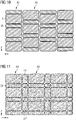
- Figs. 10 and 11 are schematic top views illustrating exemplary arrangements of a plurality of reflective surface sections.
- Fig. 10 illustrates an embodiment for an imprinted surface structure that comprises sequences of reflective surface sections 3' that are separated by transition surface sections 25 in y-direction.
- displaced reflective surface sections 3' form a first subgroup 61 of reflective surface sections that may have a first type of inclination.
- a second subgroup 63 of reflective surface sections 3' may provide a sequence having reflective surface sections with a different inclination.
- Shifted again in x-direction there is a further subgroup of reflective surface sections 3' that extends in y-direction and may differ again in inclination or have one of the inclinations of the previous subgroups 61, 63.
- Fig. 10 illustrates the possibility to form a mosaic-like structure with a variety of different subgroups of reflective surface sections having identical or different orientation in space.
- Fig. 11 has additionally transition surfaces in between rows (subgroups, sequences) such as exemplary shown transition surface sections 25' and 25" between subgroup 61' and subgroup 63'.
- the additional transition surface sections may be caused by the respective manufacturing process and may contribute themselves to the scattering/reflection features, thereby, for example, supporting the breaking up of any reflected image.
- the plurality of reflective surface sections may be orientated with respect to the surface base shape to form a step-like sequence of reflective surface sections having identical and/or varying step shapes including identical and/or varying sizes, angles, and shapes - such as plane or curved shapes discussed below.
- Figs. 12 to 15 are schematic cross-sections of chromatic reflective units illustrating embodiments with non-planar reflective surface sections.
- Fig. 12 shows an alternative to the embodiment of Fig. 7 wherein, in a modular configuration, the planar chromatic mirror units 53 of Fig. 7 are replaced by concave mirror units 53A - having, for example, a configuration as described above in connection with Figs. 7 to 9 .
- the concave shape is given in the plane of the cross-section given by the y-direction, while the shape in the x-direction (or generally along another direction defined by the surface-like base shape of the chromatic reflective unit) may be uncurved or follow the respective surface-like base shape.
- the concave shape results in a (one-dimensional) focusing feature of each chromatic mirror unit and, thus, the chromatic reflective unit in general.
- the configuration of Fig. 12 can focus an illuminating light beam in one direction.
- Fig. 13 uses convex chromatic mirror units 53B.
- Convex chromatic mirror units 53B may have, for example, a configuration as described above in connection with Figs. 7 to 9 and cause a defocusing and accordingly associate, for a specific observer position, a viewing direction 13 (see Fig. 2 ) with a plurality of directions of the incident light 9.
- a broadening of the reflected light beam in case of directional illumination e.g. sun illumination
- a smoothing of the illuminance on the ground may be achieved.
- Figs. 14 and 15 illustrate, for sandwich-type configurations, embodiments similar to the ones of Figs. 12 and 13 .
- sandwich-type configurations, and in particular surface imprinted structures allow a very flexible formation of non-planar reflective surface section.
- the non-planar shapes may generally be varied in x- and/or y-direction or generally over the complete viewable face 50. Thereby, on a small scale, a mosaic-like structure can be provided with the optical effects discussed in connection with Figs. 12 and 13 .
- Figs. 16 to 18 illustrate the flexibility that is available for orienting reflective surface structures for modular configurations and sandwich-type configurations.
- Fig. 16 illustrates an embodiment in which chromatic mirror units 53C are inclined with respect to y-direction in a random manner.
- the random orientation of the various chromatic mirror units 53C provides for a breaking of the mirrored image because an observer sees, for a specific viewing direction, various sections of the incident light (see also discussion in combination with Fig. 23 ).
- FIG. 17 A more regular configuration of chromatic mirror units is shown in Fig. 17 , which includes alternating subgroups 65A, 65B in y-direction, each having a respective orientation/inclination. Thereby, configurations are possible that specifically link a viewing direction with two regions of the incident light. In illuminated configurations with essentially a single incident direction, this aspect allows to provide the sky-sun impression at various observer locations.
- Fig. 18 illustrates a configuration in which a random-like orientation is combined with a concave configuration of the reflective surface sections 3A'.
- the embodiment combines the aspect of focusing (or alternatively defocusing) with the effect of randomness.
- Fig. 18 illustrates further the concept of an associated (section) normal na for curved surface sections - in analogy to planar surface normals (which are considered to be an associated normal within the herein disclosed concepts).
- a curved surface will generate a reflected beam that can be associated with a main beam direction after the reflection. That main beam direction and incident beam direction define the associated normal.
- the associated normal na are non-parallel. If the maintenance of some beam like behavior is intended, a range of possible directions into which the associated (section) normals na point may extend around a subgroup inclination angle.
- the subgroup inclination angle refers herein to those reflective surface sections that are contributing the visual perception and relates to the surface type of the chromatic reflective unit.
- the subgroup inclination angle may be in the range from, for example, about 2° to about 88°, in particular in the range from about 5° to about 60° such as in the range from about 10° to about 30°.
- associated normals na are inclined with respect to a unit normal that is associated with a respective portion of a surface-type of the chromatic reflective unit by inclination angles. For a given inclination direction (e.g.
- inclination angles of the associated normal na may be within an angular range up to, for example, about 30° with respect to the subgroup orientation direction such as within an angular range of up to about 20°, 10°, or 5°. In some embodiments, inclination angles of the associated normal na may not be limited with respect to the subgroup orientation direction, thereby allowing implementations for a larger potential incident angles of, for example, an incident light beam emitted by a light source.
- the inclination angles associated with respective chromatic reflective sections in Figs. 12 to 18 may be in the range from about 2° to about 80° such as in particular in the range from about 10° to about 40°.
- the above discussed configuration illustrate the possibility to provide - with respect to a single one of the respective surface sections or with respect to a plurality of reflective surface sections - a constant or varying scattering characteristic, a constant or varying nanoparticle distribution, and/or a constant or varying inclination angle of the reflective surface sections.
- Those aspects affect the chromatic feature of the chromatic reflective units for specific viewing directions.
- chromatic reflective units In the following, exemplary application of chromatic reflective units are described, in particular with respect to outdoor concepts and indoor concepts. In general, the herein described chromatic reflective units may extend over areas of several square centimeter (e.g. for illumination configurations), up to several 100 square centimeter, up to even several square meter (e.g. for facade configurations).
- FIG. 19 A facade application is explained in connection with Figs. 19 to 31 .
- a top section of a building 71 is covered by chromatic reflective structural units 73 each comprising a plurality of chromatic mirror units 53.
- the configuration of Fig. 19 is schematically illustrated in Fig. 20 in a side view.
- structural units 73 are mounted and configured to provide a chromatic effect for an observer 75 looking towards the structural unit 73 from, for example, the ground.
- structural units 73 are a measure to affect the visual appearance of building 71 by using the chromatic feature under natural illumination.
- the natural illumination may include cloudy weather conditions such as shown in Fig. 19 and discussed in connection with Figs. 22 and 23 as well as partly sunny conditions such as shown in Fig. 21 .
- the various chromatic mirror units 53 will be perceived as having a bluish color with varying blue tones and purity levels, even in case of a cloudy day - see the above description in connection with Fig. 2(b) .
- a partly sunny day is illustrated.
- An observer sees a portion 77Y of structural units 73 that is dominated in appearance by the reflected sunlight and that is perceived yellow, like the sun.
- Region 79B around the yellow dominated portion 77Y is perceived, however, blueish in color in a sky-like appearance.
- the luminance of structural units 73 effects also the illumination conditions on the streets or inside of neighboring buildings when the downwards guided/reflected light is entering rooms through windows.
- the herein disclosed structural configurations may increase the illumination and may remove or at least reduce the narrow impressions created by skyscrapers and tall buildings in general.
- the chromatic reflective units are sensitive to an anisotropy of the outdoor illumination that is transferred into an inhomogeneous chromatic appearance of a building.
- Figs. 22 and 23 are schematic illustrations for inhomogeneous luminance conditions of the sky for a clouded day.
- Fig. 22 illustrates a two-dimensional scan of the hemispherical sky luminance distribution by a luminance meter.
- the sun will provide for an increased luminance at some brighter portions 81 of the sky hemisphere while other darker portions 83 may have a rather low luminance.
- the portions close to the horizon 80 and the northern part of the sky hemisphere are reduced in luminance.
- the vertical plane containing dashed line 82 separates the hemisphere in two halves 82A and 82B. Only half 82A (i.e. essentially the part of the sky hemisphere in Fig. 22 extending from 80° over S to 260°) would contribute to illuminating the chromatic reflective unit. In addition, the ground extending from below the chromatic reflective unit to horizon 80 would contribute to illuminating the chromatic reflective unit
- inclining the orientation of the reflective surface section of the chromatic reflective unit reduces the contribution of the sky hemisphere as indicated by a solid line 84.
- Portion 84A is smaller than half 82A and comprises usually some of brighter portions 81 and darker portions 83. While the contribution of the sky hemisphere is angularly reduced, some "ground” contribution may instead generally be gained. Those gained "ground” contributions usually relate to the chromatic reflective unit which extends towards the ground. For example, light originating from transition section 25 in Fig. 3 may illuminate the above laying reflective surface sections 3'.
- the luminance of the ground is generally reduced with respect to the luminance of the sky hemisphere.
- Fig. 23 illustrates the luminance by the size of arrows associated with various directions when looking at portion 84A of the sky hemisphere via a single reflective surface sections 3' of a chromatic reflective unit.
- arrows 85 relate to brighter (high luminance) portions 81
- arrows 87 relate to darker (low luminance) portions 83.
- a chromatic reflective section 3' of the chromatic reflective unit in particular a reflective surface section, is looked at under an observation angle that reflects light from a bright region 81' of brighter high luminance portions 81 into the eye of an observer 75A, more yellow, warmer light will be superimposed onto blue diffuse light 11.
- an observer 75A will see light coming from reflective surface sections 3' with a color shifted from blue (pure Rayleigh contribution) to lighter blue (i.e. with lower color purity, drifted to white), or even progressively to white and yellow..
- an observer 75B may look via the reflection at reflective surfaced section 3' of the chromatic reflective unit in a direction that points to a darker region 83' of low luminance portions 83, the respective chromatic reflective section appears in a blue color with higher purity (with respect to the case of observer 75A) because of less white/yellow light being superimposed onto diffuse blue light 11.
- chromatic mirror units 53 of structural units 73 face, for example, down to earth having an in general lower luminance than the sky.
- an exemplary configuration of a structural unit 91 is mounted to a wall 93 is illustrated.
- chromatic mirror units 53 are inclined with respect to the normal of the wall (corresponding to the normal of the viewable side of structural unit 91) by being mounted under the respective angle via a mounting structure 95.
- an observer's potential field of view includes specular reflected light from a lower portion of the sky hemisphere and the ground when looking up to structural unit 91.
- chromatic mirror units 53 are a plurality of elongated plane (chromatic) mirrors mounted on mounting structure 95 as a mechanical support. Accordingly, a sequence or an array of reflective surface sections with vertical development is formed. From an observation point at the ground or lower levels, the mounting structure may, for example, be hidden behind mirrors. Looked at from the ground, structural unit 91 extends then as a continuous reflector on wall 93. Accordingly, the array of plane mirrors are configured to, from a perceptional point of view, be considered as continuous viewable face although having a modification in color due to the inhomogeneous luminance of the surrounding.
- Fig. 25 illustrates a specific mounting configuration of elongated chromatic mirror units 53.
- chromatic mirror units 53 are mounted to linear guiding tracks 97 (extending in x-direction) and respective slots at side wall 99 of mounting structure 95.
- the inclination together with the height of chromatic mirror units 53 defines the thickness of structural unit 91.
- Mounting structure 95 and chromatic mirror units 53 are made such that the various plane chromatic mirror units 53 are safely secured at the wall and fulfil building requirements.
- Fig. 26 illustrates an alternative mounting configuration that is based on a sequence of vertically extending bars 101 having angled slots therein into which chromatic mirror units 53 are screwed. Bars 101 enable the formation of large facade structures that are easily mountable to building
- the wall of building 71 can be completely ( Fig. 27 ) or partially ( Figs. 28 and 29 ) be covered with structural units 91.
- the shaded areas 103 are provided with structural units 91 such as exemplarily shown in Fig. 24 or 26 .
- a complete wall with the exception windows 105 will be covered and therefore be affected in its appearance by the chromatic effect.
- the appearance of building 71 is cut into parts.
- the perceived shape of building 71 can be altered, for example, in a pointing manner as illustrated in the configuration shown in Fig. 29 .
- Figs. 30 and 31 show exemplary embodiments of panel shaped chromatic mirror units 53 as they can be used in chromatic reflective units such as shown in Fig. 7 or Fig. 24 the latter as a general example of frame based modular structural units.
- Fig. 30 illustrates a glass panel based chromatic mirror unit 53C.
- the glass panel 109 for example a safety glass panel, forms a part of the support structure of a chromatic reflective unit and has a reflective layer 111 applied on one side and a chromatic diffusing layer 113 applied on the other side.
- the mirror unit may comprise, for example, through holes 115 for attaching the mirror unit to a grid configured for mounting mirror unit 53 under the desired inclination.
- glass panel 109 may be replaced by transparent panels made of, for example, a polymeric, e.g. an acrylic, polycarbonate, PVC or the like material. Respective non glass materials may simplify the mounting and reduce the weight of chromatic mirror unit 53C.
- a polymeric e.g. an acrylic, polycarbonate, PVC or the like material.
- Respective non glass materials may simplify the mounting and reduce the weight of chromatic mirror unit 53C.
- Mirror unit 53D comprises a mount-sided stabilizing layer 117, a core layer 119, and an illumination-sided stabilizing layer 121 thereby forming a composite panel such as an aluminum composite panel that forms a part of the support structure of a chromatic reflective unit.
- the reflective layer sections 3' may be provided by the illumination-sided stabilizing layer itself (e.g. by an aluminum layer) or they may be applied separately thereon by a reflective layer.
- Chromatic diffusing layer 5 is then applied onto illumination-sided stabilizing layer 121 or that reflective layer.
- Figs. 32 and 33 illustrate an outdoor configuration in which structural unit at building 71 (configured as described above in connection with Figs. 19 to 21 and 24 to 26 and mounted to building 71) is illuminated in particular at night by a projector 123.
- Projector 123 may be a light source such as disclosed, for example, in in the international patent application PCT/EP2014/001293, filed on 13 May 2014 by the same applicants.
- projector 123 is positioned such that light of a light beam 125A of projector 123 is essentially falling from the side onto structural unit 91 where it is then reflected downwards as a reflected light beam 125B onto ground 127.
- Fig. 33 illustrates the appearance of structural unit at building 71 seen from slightly above reflected light beam 125B. Specifically, when looking at structural unit at building 71, one will see the blue diffuse light scattered from within the chromatic diffuse layer. That means a sky-like appearance may be achieved at night.
- reflected light beam 125B will provide for an illumination of ground 127 essentially in the yellow tuned color of the projector.
- Fig. 34 illustrates an exemplary indoor configuration for an illumination application of the chromatic reflective units described herein.
- a chromatic reflective unit 1E is mounted to wall 131A'.
- Projector 123 is mounted to ceiling 131B or close to ceiling 131B, for example, at wall 131A" opposing chromatic reflective unit 1E and emits light beam 125A onto chromatic reflective unit 1E.
- reflected light beam 125B falls onto floor 131C.
- the chromatic diffusing layer can produce a chromatic separation (in terms of correlated color temperature CCT) of the regular (specular) reflected light of reflected light beam 125B from the scattered diffuse light.
- CCT correlated color temperature
- the correlated color temperatures of the diffuse light will be larger than the correlated color temperature of the specular reflected light, for example by a factor 1.2 or 1.1 or the like.
- a sunlight imitating lighting system can be generated as described in the initially introduced applications.
- chromatic reflective unit 1 may occur that each surrounded by a blue appearance due to diffuse scattered light. They may appear to an observer, for example, as reflections of the sun light on an irregular surface such as reflections of sun light on the waves on a lake.
- Fig. 35 does exemplarily show embodiments for such a sun-like blinking perception for a chromatic reflective unit having non-coplanar reflective surface sections.
- an observer looks at a chromatic reflective unit 401 that is illuminated by a light source 402.
- light source 402 emits a light beam 403 having, for example, an angular divergence in the range up to 80°, such as in a range up to 60°, or a range up to 40° or less.
- Chromatic reflective unit 401 may be configured so that the non-coplanar reflective sections 3' are connected and form a continuous coarse grain surface 410. Exemplary cut-views of coarse grain surface 410 are shown in Figs. 35(b) and 35(c) and exemplary top views are shown in Figs. 35(d) to 35(f) .
- coarse grain surface 410 is essentially completely illuminated by light beam 403 such that the complete coarse grain surface 410 can be considered a source of Rayleigh-like scattered light B (considered to provide a blue color for a sky-like impression) as indicated for three points P1, P2, and P3 on coarse grain surface 410.
- the observer may perceive, however, primarily a strong specularly reflected portion Y1, Y3 of light beam 403, e.g. indicated for points P1 and P3.
- the surface is inclined such that the respective portion Y2 of light beam 403 is reflected towards the ground in front of the observer such that the observer only perceives scattered light contributions B from point P2.
- the extent of bright light associated with an area on coarse grain surface 410 depends on the extent of the surface that fulfills the specular reflective conditions (in general at least subgroups of non-coplanar surface sections are formed by the coarse grain structure, in particular the mosaic-like surface structures).
- the required size will be apparent to the skilled person. For example, it depends on the geometry of the illumination system, in particular the distance of the observer to coarse grain surface 410. Depending on the expected distance of the observer to the chromatic reflective unit, surface sections 3' may have the size of several square millimeters or few square centimeters.
- reflected beams n1' to n3' are indicated as dashed lines in Fig. 35(a) .
- Fig. 35 may provide the vision of glittering light peaks (portions Y1,...) based on directed light beam 403, where the glittering light peaks may alternate with sky-like fragments (scattered light B).
- Chromatic reflective unit 401 may be configured so that non-coplanar reflective surface sections 3' are connected and form a continuous surface.
- Fig. 35(b) illustrates as a first exemplary embodiment a smooth surface providing reflective surface sections 3' that essentially fulfill similar specular reflection conditions.
- a light beam portion 403' is indicated that is specularly reflected by a reflective surface section to form an illuminating beam portion 403A'.
- a respective associated normal na is illustrated for that reflective surface section.
- Fig. 35(c) illustrates as a second exemplary embodiment in which the smooth surface of Fig. 35(b) is composed of essentially planar facets.
- the second embodiment again provides a reflective surface sections 3' that provides specular reflection conditions illustrated by an associated normal na, which in this case corresponds to the normal of the planar facet.
- coarse grain surface 410 may be made of a multitude of planar or quasi-planar surface sections of various shapes and extends.
- the shapes and extends may be configured with higher or lower degree of regularity, order, and/or periodicity such as with a limited number of types of surface sections, shapes, or inclinations.
- the continuous reflective surface may be completely (as shown in Figs. 35(b) and 35(c) ) or partially coated with a chromatic diffusing layer 5 to provide (blue) scattering at angles of observation for each single section, i.e. at angles different from the specular reflection direction of light beam 403, which is the main illumination contributions, and thus away from yellow bright luminance in the specular reflection direction.
- This aspect of - in 2D - mosaic like segmentation of specular reflectivity conditions in combination with the nanoparticle based Rayleigh-like scattering may provide the appearance of many glittering light peaks (beam portions Y) - which will be perceived similar to the case of sun reflected in the water - together with scattered light regions, which may be perceived as sky-like fragments.
- this effect may even be increased when the reflective surface sections are configured in a partly irregular arrangement, with many different shapes, sizes and orientations and with different rays of curvatures, even the limit case of a non-regular and non-periodic sinusoidal (wave-like) profile may provide the desired effect.
- Figs. 35(d) to (f) illustrate exemplary mosaic-like surface structures 412 of continuous coarse grain surfaces 410.
- the plurality of mosaic-like surface structures 412 are configured to form a faceted surface and provide a plurality of facet-like surface sections for interacting with light beam 403.
- a correlation area of mosaic-like surface structures 412 is selected to provide for a fragmentation of the vision of the emitting area of light source 402 when seen along an optical path including continuous coarse grain surface 410 from the target illumination/observer area.
- the plurality of surface sections are configured to redirect incident light beam portions such that the light beam downstream the continuous coarse grain surface 410 is broadened in size - similar to line 407 of constant brightness indicated in Fig. 25 . Thereby, the illuminance values on the target illumination/observer area are reduced, while redirected light beam portions exhibit local luminous peaks with a luminance comparable to the luminance of the emitting surface of light source 402.
- the correlation area of the mosaic-like surface structures corresponds essentially to the average transversal size of the single mosaic-like surface structure such as one complete surface oscillation (e.g. from a deepest point to a highest point to the next deepest point on the surface).
- the correlation area is essentially comparable in size to the size of the (light interacting) surface section. Accordingly, to be visually resolvable, it is in the range from, for example, about 0.5 mm to 1 m.
- the reflective surface section is a fraction of the correlation/transversal size (for example, half in a symmetric geometric shape or even a larger percentage depending on the inclination of the facet structure).
- transversal in this context refers to the surface-type, e.g. a plane parallel to the central plane. Correlation is a defined mathematical term (here the 2D-correlation). It is noted that in case of a non-planar surface, correlation scales larger than the section may appear (e.g. if the unit is curved or itself sinusoidal).
- continuous coarse grain surface 410 comprises several types of pyramids that are arranged to completely cover the surface in a regular arrangement. Thereby, also a set of regularly distributed and identically oriented reflective surface sections are formed.
- continuous coarse grain surface 410 shown in Fig. 35(e) comprises many more types of different geometrical shapes including inter alia pyramid-like shapes and wedge-like shapes.
- the geometrical shapes are mosaic-like arranged to completely cover the surface in an irregular arrangement. Thereby, also a set of irregularly distributed and differently oriented reflective surface sections are formed that in addition vary in size.
- continuous coarse grain surface 410 of Fig. 35(f) comprises various types of different shapes that are in general related to geometrical shapes but may - for example due to the processing procedure - to some extend rounded.
- the faceted structure is made of curved facets that are located either directly next to each other or are separated by some planar transition surface section.
- the structures have, for example, again pyramid-like shapes and wedge-like shapes.
- the height of the mosaic-like structure may vary more than in Fig. 35(e) . Thereby, again a set of irregularly distributed and differently oriented and differently sized reflective surface sections are formed.
- the x (or y) size of the sections may be configured so that, for an observer standing in the installation ambient, the individual surface sections are optically resolvable by eye in order to appreciate color and brightness variations.
- reflective sections may extend about or larger than 1 mm, such as few centimeters or even larger than 0.2 m.
- the surface sections may be larger than 5 mm, such as 0.3 m, or even larger than 0.5 m.
- the chromatic reflective units based on mosaic-like surface structures provide in appearance a fragmentation (such as a partition-chopping-splitting) of the source in many smaller perceived sources with comparable (in general not significantly reduced) luminance but with significant smaller size (angular size, for a fixed observer distance from the source).
- the illustrated illumination system produces a broadening and a smoothing of the projected light spot obtainable from the light source without the coarse-grain frost.
- the in connection with Fig. 35 disclosed embodiment introduce a type of a non-absorbing Rayleigh-like scattering coarse-frost unit based on non-coplanar surface sections.
- the configuration combines the chopping of luminance into small regions with diffusing the blue component as a Rayleigh diffuser.
- continuous coarse grain surface 410 may be coated with a chromatic diffusing layer as disclosed herein.
- embodiments may be combined, e.g. in a façade element or in one illumination system such as combining on a chromatic reflective unit random and plan-parallel reflective surface sections.
- a combination of a reflective panel with the Rayleigh-like scattering has also advantages on lighting systems in general.
- An exemplary lighting system will be described in connection with Fig. 36 below, wherein the lighting system is based on a large panel structure not limited to reflective layers as described before (those being based on a plurality of non-coplanar surface sections and formation of a plurality of non-coplanar reflective surface sections).
- the aspects of the nanoparticle layer are summarized for the as high concentration Rayleigh-like scattering embodiment in the following. It is noted again that those aspects do apply to structures disclosed before (forming inter alia non-coplanar reflective surface sections) as well as e.g. panel structures and coatings. For example, the skilled reader will further appreciate that some aspects discussed above for the non-coplanar designs such as inclination aspects of mirror units to use ground as darker background, aspects relating to birds, aspects relating to color drifts may not be relevant under certain boundary conditions.
- Such areal density N may be defined as the number of nanoparticles per square meter, i.e. the number of nanoparticles within a volume element delimited by a portion of the surface of the nanoparticle-loaded layer having an area of 1 m 2 and corresponds to the value obtained by multiplying the number density of nanoparticle by the thickness of the layer.
- the chromatic mirror unit was also characterized from a macroscopic point of view by the use of the monochromatic normalized specular reflectance R ( ⁇ ), defined as the ratio between the specular reflectance of the chromatic reflective unit and the specular reflectance of a reference sample identical to the chromatic reflective unit except for the fact that the diffusing layer does not contain the nanoparticles having a size in the range from 10 nm to 240 nm, i.e. the nanoparticles which are responsible of preferentially diffusing the short wavelengths of the impinging radiation.
- R ( ⁇ ) defined as the ratio between the specular reflectance of the chromatic reflective unit and the specular reflectance of a reference sample identical to the chromatic reflective unit except for the fact that the diffusing layer does not contain the nanoparticles having a size in the range from 10 nm to 240 nm, i.e. the nanoparticles which are responsible of preferentially diffusing the short wavelengths of the impinging radiation.
- the monochromatic normalized specular reflectance at wavelength 450nm could be further reduced by increasing the areal density of nanoparticles. This decrease in R has the following advantages:
- R(450nm) can be in the range from 0.003 to 0.01, for example from 0.005 to 0.009.
- a lighting system 501 is illustrated schematically in a cut view for illuminating, for example, an indoor room
- Lighting system 501 comprises a light source 502, configured to emit light in an emission solid angle to form a light beam 503 (in Fig. 1 delimited by dashed lines 513) propagating along a main light beam direction 504 (also referred to as main beam axis).
- light source 502 can be, for example, a cool white light source.
- Exemplary embodiments of light sources may comprise LED based light emitters or discharge lamp based light emitters or hydrargyrum medium-arc iodide lamp based light emitters or halogen lamp based light emitters and respective optical systems downstream of the respective light emitter.
- Lighting system 501 further includes a chromatic reflector unit 506 that couples the light originating from light source 502 to a region to be lit up.
- reflector unit 506 comprises a reflective structure 508 providing a reflective surface 508A and chromatic panel structure 510.
- Reflective unit 506 may further comprise a support structure (such as frame 514).
- the support structure may comprises a supporting structure made of glass, a sandwich structure, PMMA, a metal such as aluminum having applied thereon and/or integrated therein the reflective layer 508 and/or the chromatic diffusing layer 510, and wherein in particular the sandwich structure is an aluminum or steel composite panel having a mount-sided stabilizing layer, an illumination-sided stabilizing layer, and a core layer there-between, wherein the reflective layer is provided on or integrated into the illumination-sided stabilizing layer and the chromatic diffusing layer is applied onto the reflective layer or onto the illumination-sided stabilizing layer.
- Reflective surface 508A is generally any type of optical acting interface that reflects light having passed through chromatic panel structure 510.
- reflective surface 508A may be a surface of an aluminum layer or an interface between components, such as a reflective coating. Due to reflective surface 058A, light of light beam 503 being incident on reflective surface 508A is redirected to pass again through chromatic panel structure 510, thereafter forming an illuminating light beam 503A (delimited by dash-dash-dotted lines 507A). In Fig.
- Illuminating light beam 503A is, thus, directed in the to be illuminated region and comprises directed light (herein also referred to as directed (light) component of the lighting system).
- Chromatic panel structure 510 is generally configured for emitting diffuse light (later also referred to as diffuse (light) component of the illumination system) at a first color, e.g. in case of a sky imitation a bluish sky color, extends in front of reflective surface 508A, and comprises a visible front area section 510A that an observer can see when looking at reflector unit 506.
- a frame-like area 514A of a frame structure 514 extends next to and surrounding visible front area section 510A.
- the first color and the second color may be separated in the CIE 1976 (u',v') color space by, at least 0.008 such as at least 0.01, 0.025, or 0.04, where the color difference ⁇ u'v' is defined as the Euclidean distance in the u'v' color space.
- the illuminating light beam CCT of the second color may be close to the Planckian locus (e.g. in the range from 800 K to 6 500 K).
- the second color may correspond to u'v' points with a maximum distance from the Planckian locus of e.g. 0.06.
- a distance from the Planckian locus is, for example in the range from 800 K to 6500 K, given by ⁇ u'v' ⁇ 0.060.
- the color and/or CCT of light beam 503 and illuminating light beam 503A may be essentially identical or may differ.
- the CCT difference may be, for example, at least 300 K or even 1 000 K or more.
- an observer may have an optical perception as schematically indicated in Fig. 36 within range 507.
- the optical perception essentially depends on reflector unit 506 and the light coming therefrom as illustrated by dash-dotted lines 507B being specific for the respective observer position.
- lighting system 501 is configured such that light of significant intensity incident within range 507 of sun-observer locations originates from chromatic panel structure 510.
- the light of significant intensity comprises light of light beam 503A (originating from light source 502 and being light of light beam 503 redirected by reflector unit 506), and diffuse light originating from visible front area section 510A.
- the optical perception will - for the embodiment of Fig. 1 - comprise a, for example dark colored, frame-like area 518 around visible front area section 510A.
- the observer when looking from within range 507 of sun-observer locations onto reflector unit 506, will see a large area 516 corresponding to visible front area section 510A based on the homogenously emitted diffuse light at the first color. Large area 516 will be surrounded by frame-like area 518. In addition, the observer will see a sun-like spot 519 at the second color caused by the a reflected (directed non-diffuse) component of the light of light source 502, specifically of illuminating light beam 503A. (forward scattering effects or coarse grain effects of the light system are neglected for the illustration in connection with Fig. 36 . However, those features may additionally be provided and affect, for example, the sun appearance.
- Nanoparticle-based Rayleigh-like diffusing material used in the chromatic panel structure 510 may comprise a solid matrix of a first material (e.g. resins or adhesive polymer having excellent optical transparency), wherein nanoparticles of a second material (organic or inorganic nanoparticles such as ZnO, TiO2, SiO2, Al2O3 and similar) are dispersed.
- a first material e.g. resins or adhesive polymer having excellent optical transparency
- nanoparticles of a second material organic or inorganic nanoparticles such as ZnO, TiO2, SiO2, Al2O3 and similar
- the refractive indexes of the two materials are different, and this mismatch on the refractive index on the nano-scale is responsible of the Rayleigh-like scattering phenomenon.
- the absorption of the first and the second material in the visible wavelength range can be considered negligible.
- chromatic panel structure 510 maybe uniform, in the sense that, given any point of the chromatic stratified panel, the physical characteristics of the panel in that point does not depend on the position of that point.
- the nanoparticles may be monodisperse or polydisperse, they may be spherically shaped or shaped otherwise.
- the effective diameter d of the nanoparticles falls within the range [5 nm-350 nm], such as [10 nm-250 nm], or even [40 nm-180 nm], or [60 nm-150 nm], where the effective diameter d is the diameter of the equivalent spherical particle, namely the effective diameter spherical particle having similar scattering properties as the aforementioned nanoparticles.
- a light beam passing through a diffusive layer will generate scattered light and transmitted light.
- the coating features can modify both the spectral properties and the intensity distribution of the transmitted light.
- the morphology of the layer i.e. flatness, smoothness or orange peel
- the uniformity in the transmission of an illumination profile is an important feature.
- the chromatic diffusing layer may have, for example, a thickness variation lower than 40%, for example 30%, such as 10% over lateral circular areas with diameter smaller than 20 cm, for example smaller than 10 cm, such as 3 cm. It is noted that the diameter depends on the type of installation, in particular the expected distance from an observer the chromatic diffusing panel.
- the chromatic diffusing layer may have a number of nanoparticles per unit area of the chromatic diffusing layer averaged over lateral circular areas with diameter of 2 mm, that does not vary more than 20%, for example not more than 10%, such as 5%, among lateral circular areas within every region having a diameter of 10 cm on at least 80% of the surface of the chromatic reflective unit.
Landscapes
- Physics & Mathematics (AREA)
- Chemical & Material Sciences (AREA)
- Engineering & Computer Science (AREA)
- Optics & Photonics (AREA)
- General Physics & Mathematics (AREA)
- General Engineering & Computer Science (AREA)
- Materials Engineering (AREA)
- Life Sciences & Earth Sciences (AREA)
- Geochemistry & Mineralogy (AREA)
- General Chemical & Material Sciences (AREA)
- Chemical Kinetics & Catalysis (AREA)
- Organic Chemistry (AREA)
- Dispersion Chemistry (AREA)
- Architecture (AREA)
- Civil Engineering (AREA)
- Structural Engineering (AREA)
- Spectroscopy & Molecular Physics (AREA)
- Optical Elements Other Than Lenses (AREA)
- Optical Filters (AREA)
- Finishing Walls (AREA)
- Illuminated Signs And Luminous Advertising (AREA)
- Non-Portable Lighting Devices Or Systems Thereof (AREA)
- Building Environments (AREA)
- Laminated Bodies (AREA)
Claims (18)
- Chromatisch reflektierende Einheit (506), umfassend:eine reflektierende Schicht (508), undeine chromatische Streuschicht mit einer an der reflektierenden Schicht vorgesehenen Rückseite und eine durch einfallendes Licht (504) zu beleuchtende Vorderseite, so dass durch die chromatische Streuschicht (510) tretendes einfallendes Licht (504) von der reflektierenden Schicht (508) reflektiert wird und wieder durch die chromatische Streuschicht (510) tritt, wobeidie chromatische Streuschicht eine Mehrzahl von Nanopartikeln (37) umfasst, die in einer Matrix (39) eingebettet sind, und die dazu ausgebildet ist, ein spiegelndes Reflexionsvermögen, das im Roten größer als im Blauen ist, und ein diffuses Reflexionsvermögen, das im Blauen größer als im Roten ist, bereitzustellen, wobei das Reflexionsvermögen das Verhältnis des reflektierten Flusses zu dem einfallenden Fluss unter gegebenen Bedingungen ist, wobei:die Nanopartikel eine durchschnittliche Größe d in dem Bereich von 10 nm ≤ d ≤ 240 nm aufweisen;das Verhältnis zwischen den blauen und roten optischen Streudichten γ = Log[R(450 nm)]/Log[R(630 nm)] der chromatisch reflektierenden Einheit in den Bereich von 5 ≥ γ ≥ 2,5 fällt, wobei R(λ) das monochromatisch normierte spiegelnde Reflexionsvermögender chromatisch reflektierenden Einheit ist, welches das Verhältnis zwischen dem spiegelnden Reflexionsvermögen der chromatisch reflektierenden Einheit und dem spiegelnden Reflexionsvermögen einer Referenzprobe handelt, die mit der chromatisch reflektierenden Einheit identisch ist, außer dass die chromatische Streuschicht keine Nanopartikel mit der Größe d in dem Bereich von 10 nm ≤ d ≤ 240 nm enthält;für die Richtung, die zu der reflektierenden Schicht (508) der chromatisch reflektierenden Einheit (506) senkrecht steht, das monochromatische normierte spiegelnde Reflexionsvermögen R(λ) der chromatisch reflektierenden Einheit bei einer Wellenlänge von 450 nm in dem Bereich von ungefähr 0,0025 bis ungefähr 0,15 liegt, wie durch die Gleichungen 0,0025 ≤ R(450 nm) ≤ 0,15, 0,0025 ≤ R(450 nm) ≤ 0,05, 0,0025 ≤ R(450 nm) ≤ 0,04 definiert.
- Chromatisch reflektierende Einheit (506) nach Anspruch 1, wobei für die Richtung, die zu der reflektierenden Schicht der chromatisch reflektierende Einheit senkrecht steht, das monochromatische normierte spiegelnde Reflexionsvermögen der chromatisch reflektierenden Einheit bei einer Wellenlänge von 450 nm 0,05 ≤ R(450 nm) ≤ 0,15 beträgt.
- Chromatisch reflektierende Einheit (506) nach einem der vorhergehenden Ansprüche, wobei entlang der Richtung, die zu der reflektierenden Schicht senkrecht steht, die Anzahl von Nanopartikeln pro Flächeneinheit

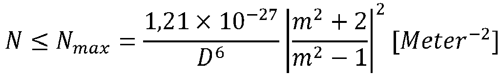

- Chromatisch reflektierende Einheit nach einem der vorhergehenden Ansprüche, ferner umfassend eine Trägerstruktur zum Tragen der reflektierenden Schicht, oderdie reflektierende Schicht als Trägerstruktur konfiguriert ist, wobeisich die reflektierende Schicht entlang der chromatischen Streuschicht erstreckt und/oder an der chromatischen Streuschicht angebracht ist und/oder an der Trägerstruktur angebracht ist.
- Chromatisch reflektierende Einheit nach einem der vorhergehenden Ansprüche, wobei der relative Brechungsindex

- Chromatisch reflektierende Einheit nach einem der vorhergehenden Ansprüche, wobei der maximale Füllungsanteil f ≤ 0,4 ist, wie etwa f ≤ 10-2 .
- Chromatisch reflektierende Einheit nach einem der vorhergehenden Ansprüche, wobei die chromatische Streuschicht eine Dickenvariation von weniger als 40 %, beispielsweise 30 %, wie etwa 10 % über laterale Kreisflächen mit einem Durchmesser von weniger als 20 cm, beispielsweise 10 cm, wie etwa 3 cm, aufweist.
- Chromatisch reflektierende Einheit nach einem der vorhergehenden Ansprüche, wobei die Anzahl von Nanopartikeln pro Flächeneinheit der chromatischen Streuschicht, gemittelt über laterale Kreisflächen mit einem Durchmesser von 2 mm, um nicht mehr als 20 %, beispielsweise um 10 %, wie etwa um 5 %, unter laterale Kreisflächen innerhalb jeder Region mit einem Durchmesser von 10 cm auf mindestens 80 % der Fläche der chromatisch reflektierende Einheit variiert.
- Chromatisch reflektierende Einheit (506) nach einem der vorhergehenden Ansprüche,wobei die reflektierende Schicht die Substratstruktur kontinuierlich erweitert und insbesondere direkt auf die Substratstruktur aufgetragen und strukturell direkt damit verbunden ist; und/oderwobei die reflektierende Schicht eine durchgehende Metallschicht auf der Substratstruktur ist; und/oderwobei die reflektierende Schicht eine Dicke aufweist, die ein Reflexionsvermögen von mindestens 65 % oder sogar mindestens 75 % oder sogar mindestens 85 %, wie etwa 90 %, für Licht, das durch die chromatische Streuschicht gegangen ist, bereitstellt; und/oderwobei die chromatische Streuschicht eine Dicke von 1 mm bis 2 mm oder eine Dicke, die geringer als die laterale Erstreckung ist, wie etwa weniger als 50 % der lateralen Erstreckung, z. B. weniger als 0,5 mm, wie etwa in dem Bereich von ungefähr 0,1 mm aufweist; und/oderwobei die reflektierende Schicht durch einen Oberflächenabschnitt der Trägerstruktur gebildet ist.
- Chromatisch reflektierende Einheit (506) nach einem der vorhergehenden Ansprüche, wobei mindestens ein Teil der reflektierenden Schicht eine Form aufweist, die insbesondere eben oder gekrümmt, wie etwa konvex oder konkav, ist.
- Chromatisch reflektierende Einheit (506) nach einem der vorhergehenden Ansprüche, wobei die chromatisch reflektierende Einheit (506) ferner eine Montagestruktur, wie etwa eine Rahmenstruktur zum Montieren der chromatisch reflektierenden Einheit, insbesondere der Trägerstruktur, der reflektierenden Schicht und/oder der chromatischen Streuschicht, umfasst.
- Chromatisch reflektierende Einheit (506) nach einem der vorhergehenden Ansprüche, wobei die Trägerstruktur eine Trägerstruktur umfasst, die aus Glas, einer Sandwichstruktur, PMMA, einem Metall, wie etwa Aluminium, auf das die reflektierende Schicht und/oder die chromatische Streuschicht aufgetragen und/oder darin integriert sind, hergestellt ist, und wobei insbesondere die Sandwichstruktur eine Verbundplatte aus Aluminium oder Stahl ist, die eine montageseitige Stabilisierungsschicht, eine beleuchtungsseitige Stabilisierungsschicht und eine Kernschicht dazwischen aufweist, wobei die reflektierende Schicht auf der beleuchtungsseitigen Stabilisierungsschicht und der chromatischen Streuschicht bereitgestellt oder darin integriert ist, und die chromatische Streuschicht auf die reflektierende Schicht oder auf die beleuchtungsseitige Stabilisierungsschicht aufgetragen ist.
- Chromatisch reflektierende Einheit (506) nach einem der vorhergehenden Ansprüche, wobei eine Differenz im Brechungsindex der Nanopartikel (37) im Verhältnis zu dem Brechungsindex der Matrix (39), eine Größenverteilung der Nanopartikel (37) und eine Anzahl von Nanopartikeln (37) pro Flächeneinheit ausgewählt werden, um das spiegelnde Reflexionsvermögen, das im Roten größer als im Blauen ist, und das diffuse Reflexionsvermögen, das im Blauen größer als im Roten ist, bereitzustellen, und wobei insbesondere der Unterschied im spiegelnden Reflexionsvermögen und diffusen Reflexionsvermögen als durchschnittliche Werte im Verhältnis zu einem blauen Teil und einem roten Teil im sichtbaren Lichtspektrum, z. B. innerhalb eines blauen Teils in dem Spektralbereich von 450 nm bis 500 nm und eines roten Teils in dem Spektralbereich von 620 nm bis 670 nm, angegeben werden.
- Chromatisch reflektierende Einheit (506) nach einem der vorhergehenden Ansprüche, wobei die Nanopartikel (37), die zu den Unterschieden im spiegelnden Reflexionsvermögen und diffusen Reflexionsvermögen beitragen, als Rayleigh-artig wirkende Streuer bezeichnet werden, und die Rayleigh-artig wirkenden Streuer und die Matrix (39) im Wesentlichen nicht absorbierend sind.
- Chromatisch reflektierende Einheit (506) nach einem der vorhergehenden Ansprüche, wobei die chromatische Streuschicht eine matrixbasierte Schicht, wie etwa eine Beschichtung, eine Farbe oder ein Grundmaterial, ist.
- Chromatisch reflektierende Einheit (506) nach einem der vorhergehenden Ansprüche, wobei die chromatische Streuschicht ferner Partikel, die zur Absorption eines begrenzten Spektralbereichs, wie etwa im Infrarotspektrum und/oder im ultravioletten Spektrum und/oder in einem spezifischen Spektralbereich zum Überlagern einer Färbung auf das Aussehen der chromatisch reflektierende Einheit (506) beitragen; und/oder Partikel, die eine Größe aufweisen, die größer als die Rayleigh-artig wirkenden Streuer ist, die insbesondere zu einer zunehmenden Vorwärtsstreuung beitragen, wodurch das spiegelnde Reflexionsvermögen verringert wird, und wobei das spiegelnde Reflexionsvermögen insbesondere im Wesentlichen unabhängig von der Farbe verringert wird, umfasst.
- Chromatisch reflektierende Einheit nach einem der vorhergehenden Ansprüche, wobei die chromatische Streuschicht ferner Kleinwinkel-diffuse Partikel innerhalb der Matrix und/oder eine (Mikro-) Oberflächenstruktur, die zum Bilden eines Kleinwinkel-Streukegels um das spiegelnde Reflexionsvermögen herum beiträgt und eine Größe aufweist, die größer als die Partikel der Nanopartikel ist, die als Rayleigh-artige Streuer dienen, umfasst, und
wobei die Kleinwinkel-diffusen Partikel Licht innerhalb eines Winkelfächers mit einer Halbwertsbreiten- (FWHM) Divergenz streuen, die kleiner als die FWHM-Divergenz ist, die durch den Rayleigh-artigen Diffusor generiert wird, beispielsweise dreimal kleiner, wie etwa viermal kleiner. - Beleuchtungssystem, umfassend:eine Lichtquelle (502), die dazu ausgebildet ist, einen Strahl sichtbaren Lichts zu generieren;eine chromatisch reflektierende Einheit nach einem der vorhergehenden Ansprüche, die durch die Lichtquelle (502) beleuchtet wird, wobeiein Teil des Lichtstrahls einen beleuchtenden Lichtstrahl (503) bildet, indem er durch die chromatisch reflektierende Einheit im Wesentlichen ohne Streuung tritt, und ein Teil des Lichts des Lichtstrahls durch die Nanopartikel innerhalb der chromatisch reflektierenden Einheit Rayleigh-artig gestreut wird.
Applications Claiming Priority (2)
| Application Number | Priority Date | Filing Date | Title |
|---|---|---|---|
| PCT/EP2015/001454 WO2017008821A1 (en) | 2015-07-15 | 2015-07-15 | Chromatic reflective unit |
| PCT/EP2015/002319 WO2017008824A1 (en) | 2015-07-15 | 2015-11-19 | Chromatic reflective unit |
Publications (2)
| Publication Number | Publication Date |
|---|---|
| EP3322933A1 EP3322933A1 (de) | 2018-05-23 |
| EP3322933B1 true EP3322933B1 (de) | 2022-12-28 |
Family
ID=53835378
Family Applications (3)
| Application Number | Title | Priority Date | Filing Date |
|---|---|---|---|
| EP15749715.7A Active EP3322931B1 (de) | 2015-07-15 | 2015-07-15 | Chromatische reflektierende einheit |
| EP15816660.3A Active EP3322933B1 (de) | 2015-07-15 | 2015-11-19 | Chromatische reflektierende einheit |
| EP16751488.4A Not-in-force EP3322932B1 (de) | 2015-07-15 | 2016-07-15 | Chromatische fassaden- und fenstereinheiten |
Family Applications Before (1)
| Application Number | Title | Priority Date | Filing Date |
|---|---|---|---|
| EP15749715.7A Active EP3322931B1 (de) | 2015-07-15 | 2015-07-15 | Chromatische reflektierende einheit |
Family Applications After (1)
| Application Number | Title | Priority Date | Filing Date |
|---|---|---|---|
| EP16751488.4A Not-in-force EP3322932B1 (de) | 2015-07-15 | 2016-07-15 | Chromatische fassaden- und fenstereinheiten |
Country Status (6)
| Country | Link |
|---|---|
| US (3) | US10459130B2 (de) |
| EP (3) | EP3322931B1 (de) |
| JP (3) | JP6745330B2 (de) |
| KR (2) | KR102205155B1 (de) |
| CN (2) | CN108139044B (de) |
| WO (3) | WO2017008821A1 (de) |
Families Citing this family (13)
| Publication number | Priority date | Publication date | Assignee | Title |
|---|---|---|---|---|
| WO2017008822A1 (en) * | 2015-07-15 | 2017-01-19 | Coelux S.R.L. | Reflective illumination systems for optically widened perception |
| JP6745330B2 (ja) * | 2015-07-15 | 2020-08-26 | コエルクス・エッセ・エッレ・エッレCoeLux S.r.l. | 色反射ユニット |
| JP6809378B2 (ja) * | 2017-05-26 | 2021-01-06 | トヨタ紡織株式会社 | 車室内照明装置 |
| WO2019064257A1 (en) * | 2017-09-28 | 2019-04-04 | Coelux S.R.L. | OPTICAL DEVICE FOR ENHANCED ILLUMINATION SYSTEM FOR SIMULATING NATURAL LIGHTING IN TWO HALF SPACES |
| CN108562959A (zh) * | 2018-04-25 | 2018-09-21 | 京东方科技集团股份有限公司 | 一种光学膜、具有其的背光模组及显示装置 |
| EP3599318B1 (de) * | 2018-07-27 | 2021-11-10 | (CNBM) Bengbu Design & Research Institute for Glass Industry Co., Ltd. | Fassadenelemente mit strukturierter deckplatte und optischer interferenzschicht |
| CN111367119A (zh) * | 2018-12-26 | 2020-07-03 | 海信视像科技股份有限公司 | 直下式背光灯条、背光模组及显示装置 |
| CA3130069C (en) | 2019-02-15 | 2024-01-02 | Certainteed Gypsum, Inc. | Defect-hiding surface textures |
| CN112776426B (zh) * | 2019-11-07 | 2024-06-21 | 埃米尔·夏伊·卢蒂安 | 地下无窗侧防水片材膜及其制造和使用方法 |
| ES2928504T3 (es) * | 2020-01-28 | 2022-11-18 | Cnbm Res Institute For Advanced Glass Materials Group Co Ltd | Elemento de fachada coloreado con estructura de paneles compuestos |
| IT202000008113A1 (it) * | 2020-04-16 | 2021-10-16 | Coelux Srl | Unità in riflessione di luce a effetto cromatico |
| IT202000024841A1 (it) | 2020-10-21 | 2022-04-21 | Coelux Srl | Unità di rivestimento frangisole a effetto cromatico |
| EP4437287A1 (de) * | 2021-11-23 | 2024-10-02 | Iyris Technology Limited | Transparentes foto-thermisches energieumwandlungsmodul und verfahren |
Family Cites Families (68)
| Publication number | Priority date | Publication date | Assignee | Title |
|---|---|---|---|---|
| JPS6329600Y2 (de) * | 1981-01-23 | 1988-08-09 | ||
| JPS6039853Y2 (ja) * | 1981-02-13 | 1985-11-29 | 将男 秋元 | 分光反射装飾 |
| EP0230478B1 (de) | 1984-09-07 | 1990-04-18 | Nippon Petrochemicals Company, Limited | Verfahren zur Herstellung von alpha-(p-Isobutylphenyl)propionsäure |
| JP2000122580A (ja) * | 1998-10-14 | 2000-04-28 | Wakatake Masaru | 疑似発光面体、及びそれを用いた表示素子及び表示装置 |
| US6752505B2 (en) * | 1999-02-23 | 2004-06-22 | Solid State Opto Limited | Light redirecting films and film systems |
| US6671100B1 (en) * | 1999-10-14 | 2003-12-30 | Stratos Product Development Llc | Virtual imaging system |
| JP4419231B2 (ja) * | 1999-11-10 | 2010-02-24 | 凸版印刷株式会社 | 着色光散乱シートとそれを用いた液晶表示装置。 |
| JP3951580B2 (ja) * | 2000-10-03 | 2007-08-01 | 凸版印刷株式会社 | 光拡散板 |
| JP2002207446A (ja) * | 2001-01-09 | 2002-07-26 | Nkk Corp | 擬似発光面体 |
| WO2003023400A2 (en) * | 2001-09-13 | 2003-03-20 | Axela Biosensors Inc. | Method and apparatus for assay based on light diffraction |
| JP4401681B2 (ja) * | 2003-05-19 | 2010-01-20 | 日東樹脂工業株式会社 | 光拡散体及びそれを用いた光学部材乃至光学デバイス |
| US7704740B2 (en) * | 2003-11-05 | 2010-04-27 | Michigan State University | Nanofibrillar structure and applications including cell and tissue culture |
| JP4808383B2 (ja) * | 2004-03-17 | 2011-11-02 | 富士フイルム株式会社 | 着色組成物及び感光性転写材料、表示装置用遮光層及びその製造方法、カラーフィルター、液晶表示素子並びに表示装置用遮光層付き基板 |
| WO2006007742A1 (en) * | 2004-07-21 | 2006-01-26 | Rolic Ag | Anisotropic optical devices and method for making same |
| KR20060024527A (ko) | 2004-09-14 | 2006-03-17 | 삼성전자주식회사 | 광학 유닛, 이에 채용된 광 재생 부재의 제조 방법 및이를 갖는 표시장치 |
| JP4552733B2 (ja) * | 2005-03-31 | 2010-09-29 | ソニー株式会社 | スクリーン及びその製造方法 |
| JP4684764B2 (ja) * | 2005-06-29 | 2011-05-18 | ニチハ株式会社 | 建築板及びその製造方法 |
| WO2007018039A1 (ja) * | 2005-08-05 | 2007-02-15 | Matsushita Electric Industrial Co., Ltd. | 半導体発光装置 |
| CN101208811A (zh) * | 2005-08-05 | 2008-06-25 | 松下电器产业株式会社 | 半导体发光装置 |
| US7663718B2 (en) * | 2006-02-27 | 2010-02-16 | Lg Chem, Ltd. | Very thin achromatic quarter wave film laminate for transflective LCD and method for producing the same |
| JP2008003254A (ja) * | 2006-06-21 | 2008-01-10 | Idemitsu Kosan Co Ltd | 光線反射用多層シート、これを用いた反射器、照明装置及び液晶表示装置 |
| JP2008026618A (ja) * | 2006-07-21 | 2008-02-07 | Toppan Printing Co Ltd | プロジェクションスクリーンおよびこれを用いる画像表示装置 |
| JP2008062562A (ja) * | 2006-09-08 | 2008-03-21 | Kimoto & Co Ltd | 表示用フィルム |
| KR20090084930A (ko) * | 2006-11-10 | 2009-08-05 | 휴렛-팩커드 디벨롭먼트 컴퍼니, 엘.피. | 아포크로매틱 렌즈 및 광 분리 수단을 사용하는 매체 상에서의 광학 데이터 기록 및 이미지화 |
| JP2008145942A (ja) * | 2006-12-13 | 2008-06-26 | Nippon Steel Corp | 光拡散反射材料とその製造方法、及び電子機器 |
| JP2008290900A (ja) * | 2007-05-23 | 2008-12-04 | Asahi Glass Co Ltd | 車両窓用合わせガラス |
| GB0711695D0 (en) | 2007-06-16 | 2007-07-25 | Flynn Sean | An infinity display with autostereoscopic capability |
| JP5398134B2 (ja) | 2007-11-15 | 2014-01-29 | 住友金属鉱山株式会社 | 表面処理酸化亜鉛微粒子の製造方法、表面処理酸化亜鉛微粒子、その分散液体および分散固体、並びに酸化亜鉛微粒子被覆基材 |
| ITMI20081135A1 (it) * | 2008-06-24 | 2009-12-25 | Trapani Paolo Di | Dispositivo di illuminazione |
| JP5350771B2 (ja) | 2008-12-24 | 2013-11-27 | 株式会社小糸製作所 | 車両用照明灯具 |
| US8068285B1 (en) | 2009-05-19 | 2011-11-29 | Sean Thomas Flynn | Infinity display with autostereoscopic capability |
| JP5621312B2 (ja) * | 2010-05-11 | 2014-11-12 | セイコーエプソン株式会社 | スクリーンおよびプロジェクションシステム |
| US20110010994A1 (en) * | 2009-07-15 | 2011-01-20 | Wilson Stephen S | Spectral Selective Solar Control Film Containing an Air Layer for Windows |
| JP5481764B2 (ja) * | 2009-10-08 | 2014-04-23 | スタンレー電気株式会社 | 車両用灯具 |
| WO2011063236A1 (en) * | 2009-11-23 | 2011-05-26 | 3M Innovative Properties Company | Front projection screen with high contrast |
| JP4858650B2 (ja) * | 2010-03-02 | 2012-01-18 | ソニー株式会社 | 光学体、窓材、建具および日射遮蔽装置 |
| JP6001545B2 (ja) * | 2010-10-20 | 2016-10-05 | スリーエム イノベイティブ プロパティズ カンパニー | ナノ空隙ポリマー層を組み込んだ広帯域半鏡面ミラーフィルム |
| US20120147458A1 (en) | 2010-12-09 | 2012-06-14 | Certainteed Corporation | Member for a structure including a solar control layer |
| FR2971060B1 (fr) | 2011-01-31 | 2013-08-09 | Saint Gobain | Element transparent a reflexion diffuse |
| RU2612393C2 (ru) | 2011-07-20 | 2017-03-09 | Филипс Лайтинг Холдинг Б.В. | Оптический элемент, осветительная система и светильник для обеспечения внешнего вида зенитного фонаря |
| ITRM20110384A1 (it) * | 2011-07-20 | 2013-01-21 | Seko Spa | Valvola di disconnessione a membrana flessibile, in particolare per la prevenzione del riflusso. |
| JP2013043390A (ja) | 2011-08-25 | 2013-03-04 | Sumitomo Chemical Co Ltd | 積層体およびその製造方法 |
| US8687147B2 (en) * | 2011-11-14 | 2014-04-01 | Planck Co., Ltd. | Color regulating device for illumination and apparatus using the same, and method of regulating color |
| US8698980B2 (en) * | 2011-11-14 | 2014-04-15 | Planck Co., Ltd. | Color regulating device for illumination and apparatus using the same, and method of regulating color |
| CN104245618B (zh) | 2011-12-02 | 2017-08-25 | 住友金属矿山株式会社 | 热线遮蔽膜、热线遮蔽夹层透明基体材料、以及安装该热线遮蔽夹层透明基体材料作为窗口材料的汽车、以及使用该热线遮蔽夹层透明基体材料作为窗口材料的建造物 |
| DE102012012621A1 (de) * | 2012-06-26 | 2014-01-02 | Bartenbach Holding Gmbh | Beleuchtungsvorrichtung |
| JP2014010404A (ja) * | 2012-07-02 | 2014-01-20 | Dainippon Printing Co Ltd | 反射スクリーン、映像表示システム |
| JP2014012945A (ja) * | 2012-07-04 | 2014-01-23 | Ig Kogyo Kk | 外装材 |
| US10450471B2 (en) | 2012-07-11 | 2019-10-22 | Sumitomo Metal Mining Co., Ltd. | Method for producing heat-ray shielding dispersion body, heat-ray shielding dispersion body, and heat-ray shielding body |
| EP2904436A4 (de) | 2012-10-08 | 2016-06-01 | Corning Inc | Verfahren und vorrichtung zur bereitstellung verbesserter anzeigekomponenten |
| ITTO20120988A1 (it) | 2012-11-14 | 2014-05-15 | Light In Light S R L | Sistema di illuminazione artificiale per simulare un'illuminazione naturale |
| WO2014115460A1 (ja) * | 2013-01-24 | 2014-07-31 | シャープ株式会社 | 光学部材、リフレクタ、発光装置および光照明装置 |
| US10042093B2 (en) * | 2013-04-30 | 2018-08-07 | Hewlett-Packard Development Company, L.P. | Diffuse reflectors |
| JP6416228B2 (ja) | 2013-05-30 | 2018-10-31 | フィリップス ライティング ホールディング ビー ヴィ | 天空光の見た目を得るための光学素子、及び照明器具 |
| KR101493027B1 (ko) * | 2013-08-23 | 2015-02-17 | 플루오르테크주식회사 | 광확산 도료와 글래스 비드를 포함하는 광확산 부재 및 이를 이용한 광표지판 |
| US20160266286A1 (en) | 2013-09-16 | 2016-09-15 | Coelux S.R.L. | Composite system comprising a polymer matrix and core-shell nanoparticles, process for preparing it and use thereof |
| US9372291B2 (en) | 2013-11-04 | 2016-06-21 | Sung Nae CHO | Heat blocking system utilizing particulates |
| US9320201B2 (en) * | 2013-12-20 | 2016-04-26 | Elwha Llc | Reflective articles and methods for increasing photosynthesis |
| RU2673868C2 (ru) * | 2014-05-13 | 2018-11-30 | Коэлюкс С.Р.Л. | Хроматическое зеркало, хроматическая панель и их применение |
| EP3143450B1 (de) | 2014-05-13 | 2018-03-28 | CoeLux S.r.l. | Lichtquelle und sonnenlichtimitierendes beleuchtungssystem |
| TWI494681B (zh) * | 2014-06-16 | 2015-08-01 | Coretronic Corp | 投影幕及投影幕的製作方法 |
| JP6426297B2 (ja) | 2015-02-23 | 2018-11-21 | コエルクス・エッセ・エッレ・エッレCoeLux S.r.l. | シート照明システム |
| CN107407474B (zh) | 2015-02-23 | 2020-03-24 | 科勒克斯有限责任公司 | 用于光学扩展感知的照明系统 |
| US9904063B2 (en) | 2015-06-15 | 2018-02-27 | Innerscene, Inc. | Collimating display and methods |
| WO2017008822A1 (en) | 2015-07-15 | 2017-01-19 | Coelux S.R.L. | Reflective illumination systems for optically widened perception |
| JP6745330B2 (ja) * | 2015-07-15 | 2020-08-26 | コエルクス・エッセ・エッレ・エッレCoeLux S.r.l. | 色反射ユニット |
| JP6676155B2 (ja) | 2015-09-16 | 2020-04-08 | インナーシーン,インコーポレイテッド | 人工天窓及び方法 |
| WO2017085079A1 (en) | 2015-11-19 | 2017-05-26 | Coelux S.R.L. | Stratified panel structure for sun-sky-imitating lighting systems |
-
2015
- 2015-07-15 JP JP2018502008A patent/JP6745330B2/ja active Active
- 2015-07-15 WO PCT/EP2015/001454 patent/WO2017008821A1/en not_active Ceased
- 2015-07-15 CN CN201580083104.6A patent/CN108139044B/zh active Active
- 2015-07-15 US US15/742,799 patent/US10459130B2/en active Active
- 2015-07-15 KR KR1020187004720A patent/KR102205155B1/ko active Active
- 2015-07-15 EP EP15749715.7A patent/EP3322931B1/de active Active
- 2015-11-19 CN CN201580083103.1A patent/CN108027128B/zh active Active
- 2015-11-19 KR KR1020187004728A patent/KR20180031023A/ko not_active Withdrawn
- 2015-11-19 JP JP2018502004A patent/JP6639636B2/ja active Active
- 2015-11-19 WO PCT/EP2015/002319 patent/WO2017008824A1/en not_active Ceased
- 2015-11-19 EP EP15816660.3A patent/EP3322933B1/de active Active
- 2015-11-19 US US15/742,805 patent/US10222520B2/en active Active
-
2016
- 2016-07-15 US US15/742,807 patent/US10684399B2/en not_active Expired - Fee Related
- 2016-07-15 JP JP2018501978A patent/JP6550524B2/ja not_active Expired - Fee Related
- 2016-07-15 WO PCT/EP2016/066995 patent/WO2017009478A2/en not_active Ceased
- 2016-07-15 EP EP16751488.4A patent/EP3322932B1/de not_active Not-in-force
Also Published As
| Publication number | Publication date |
|---|---|
| JP6639636B2 (ja) | 2020-02-05 |
| EP3322932A2 (de) | 2018-05-23 |
| KR20180031023A (ko) | 2018-03-27 |
| US10222520B2 (en) | 2019-03-05 |
| CN108139044A (zh) | 2018-06-08 |
| JP2018523847A (ja) | 2018-08-23 |
| US20180203166A1 (en) | 2018-07-19 |
| JP2018523165A (ja) | 2018-08-16 |
| US10459130B2 (en) | 2019-10-29 |
| US20180203165A1 (en) | 2018-07-19 |
| US20190079220A1 (en) | 2019-03-14 |
| WO2017008821A1 (en) | 2017-01-19 |
| CN108027128A (zh) | 2018-05-11 |
| EP3322931A1 (de) | 2018-05-23 |
| KR20180030889A (ko) | 2018-03-26 |
| WO2017009478A3 (en) | 2017-04-27 |
| US10684399B2 (en) | 2020-06-16 |
| JP2018522284A (ja) | 2018-08-09 |
| EP3322931B1 (de) | 2020-04-22 |
| JP6550524B2 (ja) | 2019-07-24 |
| EP3322932B1 (de) | 2020-09-02 |
| JP6745330B2 (ja) | 2020-08-26 |
| CN108139044B (zh) | 2021-06-04 |
| EP3322933A1 (de) | 2018-05-23 |
| CN108027128B (zh) | 2020-07-28 |
| KR102205155B1 (ko) | 2021-01-21 |
| WO2017008824A1 (en) | 2017-01-19 |
| WO2017009478A2 (en) | 2017-01-19 |
Similar Documents
| Publication | Publication Date | Title |
|---|---|---|
| EP3322933B1 (de) | Chromatische reflektierende einheit | |
| EP3130842B1 (de) | Lichtkuppelbeleuchtungssystem | |
| US10663632B2 (en) | Reflective illumination systems for optically widened perception | |
| EP3377813B1 (de) | Modulares sonne-himmel-imitierendes beleuchtungssystem | |
| EP3117142B1 (de) | Beleuchtungssystem | |
| CN109296996B (zh) | 色镜、色板及其应用 | |
| US10088125B2 (en) | Illumination system for optically widened perception | |
| EP3426972B1 (de) | Sonne-himmel-imitierendes beleuchtungssystem mit vergrössert wahrgenommenem fensterbereich |
Legal Events
| Date | Code | Title | Description |
|---|---|---|---|
| STAA | Information on the status of an ep patent application or granted ep patent |
Free format text: STATUS: THE INTERNATIONAL PUBLICATION HAS BEEN MADE |
|
| PUAI | Public reference made under article 153(3) epc to a published international application that has entered the european phase |
Free format text: ORIGINAL CODE: 0009012 |
|
| STAA | Information on the status of an ep patent application or granted ep patent |
Free format text: STATUS: REQUEST FOR EXAMINATION WAS MADE |
|
| 17P | Request for examination filed |
Effective date: 20180208 |
|
| AK | Designated contracting states |
Kind code of ref document: A1 Designated state(s): AL AT BE BG CH CY CZ DE DK EE ES FI FR GB GR HR HU IE IS IT LI LT LU LV MC MK MT NL NO PL PT RO RS SE SI SK SM TR |
|
| AX | Request for extension of the european patent |
Extension state: BA ME |
|
| DAV | Request for validation of the european patent (deleted) | ||
| DAX | Request for extension of the european patent (deleted) | ||
| STAA | Information on the status of an ep patent application or granted ep patent |
Free format text: STATUS: EXAMINATION IS IN PROGRESS |
|
| 17Q | First examination report despatched |
Effective date: 20191011 |
|
| GRAP | Despatch of communication of intention to grant a patent |
Free format text: ORIGINAL CODE: EPIDOSNIGR1 |
|
| STAA | Information on the status of an ep patent application or granted ep patent |
Free format text: STATUS: GRANT OF PATENT IS INTENDED |
|
| INTG | Intention to grant announced |
Effective date: 20220209 |
|
| GRAJ | Information related to disapproval of communication of intention to grant by the applicant or resumption of examination proceedings by the epo deleted |
Free format text: ORIGINAL CODE: EPIDOSDIGR1 |
|
| STAA | Information on the status of an ep patent application or granted ep patent |
Free format text: STATUS: EXAMINATION IS IN PROGRESS |
|
| GRAP | Despatch of communication of intention to grant a patent |
Free format text: ORIGINAL CODE: EPIDOSNIGR1 |
|
| STAA | Information on the status of an ep patent application or granted ep patent |
Free format text: STATUS: GRANT OF PATENT IS INTENDED |
|
| INTC | Intention to grant announced (deleted) | ||
| INTG | Intention to grant announced |
Effective date: 20220715 |
|
| GRAS | Grant fee paid |
Free format text: ORIGINAL CODE: EPIDOSNIGR3 |
|
| GRAA | (expected) grant |
Free format text: ORIGINAL CODE: 0009210 |
|
| STAA | Information on the status of an ep patent application or granted ep patent |
Free format text: STATUS: THE PATENT HAS BEEN GRANTED |
|
| AK | Designated contracting states |
Kind code of ref document: B1 Designated state(s): AL AT BE BG CH CY CZ DE DK EE ES FI FR GB GR HR HU IE IS IT LI LT LU LV MC MK MT NL NO PL PT RO RS SE SI SK SM TR |
|
| REG | Reference to a national code |
Ref country code: GB Ref legal event code: FG4D |
|
| REG | Reference to a national code |
Ref country code: CH Ref legal event code: EP |
|
| REG | Reference to a national code |
Ref country code: DE Ref legal event code: R096 Ref document number: 602015082107 Country of ref document: DE |
|
| REG | Reference to a national code |
Ref country code: AT Ref legal event code: REF Ref document number: 1540731 Country of ref document: AT Kind code of ref document: T Effective date: 20230115 |
|
| REG | Reference to a national code |
Ref country code: IE Ref legal event code: FG4D |
|
| REG | Reference to a national code |
Ref country code: LT Ref legal event code: MG9D |
|
| PG25 | Lapsed in a contracting state [announced via postgrant information from national office to epo] |
Ref country code: SE Free format text: LAPSE BECAUSE OF FAILURE TO SUBMIT A TRANSLATION OF THE DESCRIPTION OR TO PAY THE FEE WITHIN THE PRESCRIBED TIME-LIMIT Effective date: 20221228 Ref country code: NO Free format text: LAPSE BECAUSE OF FAILURE TO SUBMIT A TRANSLATION OF THE DESCRIPTION OR TO PAY THE FEE WITHIN THE PRESCRIBED TIME-LIMIT Effective date: 20230328 Ref country code: LT Free format text: LAPSE BECAUSE OF FAILURE TO SUBMIT A TRANSLATION OF THE DESCRIPTION OR TO PAY THE FEE WITHIN THE PRESCRIBED TIME-LIMIT Effective date: 20221228 Ref country code: FI Free format text: LAPSE BECAUSE OF FAILURE TO SUBMIT A TRANSLATION OF THE DESCRIPTION OR TO PAY THE FEE WITHIN THE PRESCRIBED TIME-LIMIT Effective date: 20221228 |
|
| REG | Reference to a national code |
Ref country code: NL Ref legal event code: MP Effective date: 20221228 |
|
| REG | Reference to a national code |
Ref country code: AT Ref legal event code: MK05 Ref document number: 1540731 Country of ref document: AT Kind code of ref document: T Effective date: 20221228 |
|
| PG25 | Lapsed in a contracting state [announced via postgrant information from national office to epo] |
Ref country code: RS Free format text: LAPSE BECAUSE OF FAILURE TO SUBMIT A TRANSLATION OF THE DESCRIPTION OR TO PAY THE FEE WITHIN THE PRESCRIBED TIME-LIMIT Effective date: 20221228 Ref country code: LV Free format text: LAPSE BECAUSE OF FAILURE TO SUBMIT A TRANSLATION OF THE DESCRIPTION OR TO PAY THE FEE WITHIN THE PRESCRIBED TIME-LIMIT Effective date: 20221228 Ref country code: HR Free format text: LAPSE BECAUSE OF FAILURE TO SUBMIT A TRANSLATION OF THE DESCRIPTION OR TO PAY THE FEE WITHIN THE PRESCRIBED TIME-LIMIT Effective date: 20221228 Ref country code: GR Free format text: LAPSE BECAUSE OF FAILURE TO SUBMIT A TRANSLATION OF THE DESCRIPTION OR TO PAY THE FEE WITHIN THE PRESCRIBED TIME-LIMIT Effective date: 20230329 |
|
| P01 | Opt-out of the competence of the unified patent court (upc) registered |
Effective date: 20230404 |
|
| PG25 | Lapsed in a contracting state [announced via postgrant information from national office to epo] |
Ref country code: NL Free format text: LAPSE BECAUSE OF FAILURE TO SUBMIT A TRANSLATION OF THE DESCRIPTION OR TO PAY THE FEE WITHIN THE PRESCRIBED TIME-LIMIT Effective date: 20221228 |
|
| PG25 | Lapsed in a contracting state [announced via postgrant information from national office to epo] |
Ref country code: SM Free format text: LAPSE BECAUSE OF FAILURE TO SUBMIT A TRANSLATION OF THE DESCRIPTION OR TO PAY THE FEE WITHIN THE PRESCRIBED TIME-LIMIT Effective date: 20221228 Ref country code: RO Free format text: LAPSE BECAUSE OF FAILURE TO SUBMIT A TRANSLATION OF THE DESCRIPTION OR TO PAY THE FEE WITHIN THE PRESCRIBED TIME-LIMIT Effective date: 20221228 Ref country code: PT Free format text: LAPSE BECAUSE OF FAILURE TO SUBMIT A TRANSLATION OF THE DESCRIPTION OR TO PAY THE FEE WITHIN THE PRESCRIBED TIME-LIMIT Effective date: 20230428 Ref country code: ES Free format text: LAPSE BECAUSE OF FAILURE TO SUBMIT A TRANSLATION OF THE DESCRIPTION OR TO PAY THE FEE WITHIN THE PRESCRIBED TIME-LIMIT Effective date: 20221228 Ref country code: EE Free format text: LAPSE BECAUSE OF FAILURE TO SUBMIT A TRANSLATION OF THE DESCRIPTION OR TO PAY THE FEE WITHIN THE PRESCRIBED TIME-LIMIT Effective date: 20221228 Ref country code: CZ Free format text: LAPSE BECAUSE OF FAILURE TO SUBMIT A TRANSLATION OF THE DESCRIPTION OR TO PAY THE FEE WITHIN THE PRESCRIBED TIME-LIMIT Effective date: 20221228 Ref country code: AT Free format text: LAPSE BECAUSE OF FAILURE TO SUBMIT A TRANSLATION OF THE DESCRIPTION OR TO PAY THE FEE WITHIN THE PRESCRIBED TIME-LIMIT Effective date: 20221228 |
|
| PG25 | Lapsed in a contracting state [announced via postgrant information from national office to epo] |
Ref country code: SK Free format text: LAPSE BECAUSE OF FAILURE TO SUBMIT A TRANSLATION OF THE DESCRIPTION OR TO PAY THE FEE WITHIN THE PRESCRIBED TIME-LIMIT Effective date: 20221228 Ref country code: PL Free format text: LAPSE BECAUSE OF FAILURE TO SUBMIT A TRANSLATION OF THE DESCRIPTION OR TO PAY THE FEE WITHIN THE PRESCRIBED TIME-LIMIT Effective date: 20221228 Ref country code: IS Free format text: LAPSE BECAUSE OF FAILURE TO SUBMIT A TRANSLATION OF THE DESCRIPTION OR TO PAY THE FEE WITHIN THE PRESCRIBED TIME-LIMIT Effective date: 20230428 Ref country code: AL Free format text: LAPSE BECAUSE OF FAILURE TO SUBMIT A TRANSLATION OF THE DESCRIPTION OR TO PAY THE FEE WITHIN THE PRESCRIBED TIME-LIMIT Effective date: 20221228 |
|
| REG | Reference to a national code |
Ref country code: DE Ref legal event code: R097 Ref document number: 602015082107 Country of ref document: DE |
|
| PG25 | Lapsed in a contracting state [announced via postgrant information from national office to epo] |
Ref country code: DK Free format text: LAPSE BECAUSE OF FAILURE TO SUBMIT A TRANSLATION OF THE DESCRIPTION OR TO PAY THE FEE WITHIN THE PRESCRIBED TIME-LIMIT Effective date: 20221228 |
|
| PLBE | No opposition filed within time limit |
Free format text: ORIGINAL CODE: 0009261 |
|
| STAA | Information on the status of an ep patent application or granted ep patent |
Free format text: STATUS: NO OPPOSITION FILED WITHIN TIME LIMIT |
|
| 26N | No opposition filed |
Effective date: 20230929 |
|
| PG25 | Lapsed in a contracting state [announced via postgrant information from national office to epo] |
Ref country code: SI Free format text: LAPSE BECAUSE OF FAILURE TO SUBMIT A TRANSLATION OF THE DESCRIPTION OR TO PAY THE FEE WITHIN THE PRESCRIBED TIME-LIMIT Effective date: 20221228 |
|
| PG25 | Lapsed in a contracting state [announced via postgrant information from national office to epo] |
Ref country code: IT Free format text: LAPSE BECAUSE OF FAILURE TO SUBMIT A TRANSLATION OF THE DESCRIPTION OR TO PAY THE FEE WITHIN THE PRESCRIBED TIME-LIMIT Effective date: 20221228 |
|
| PG25 | Lapsed in a contracting state [announced via postgrant information from national office to epo] |
Ref country code: MC Free format text: LAPSE BECAUSE OF FAILURE TO SUBMIT A TRANSLATION OF THE DESCRIPTION OR TO PAY THE FEE WITHIN THE PRESCRIBED TIME-LIMIT Effective date: 20221228 |
|
| PG25 | Lapsed in a contracting state [announced via postgrant information from national office to epo] |
Ref country code: LU Free format text: LAPSE BECAUSE OF NON-PAYMENT OF DUE FEES Effective date: 20231119 |
|
| PG25 | Lapsed in a contracting state [announced via postgrant information from national office to epo] |
Ref country code: MC Free format text: LAPSE BECAUSE OF FAILURE TO SUBMIT A TRANSLATION OF THE DESCRIPTION OR TO PAY THE FEE WITHIN THE PRESCRIBED TIME-LIMIT Effective date: 20221228 Ref country code: LU Free format text: LAPSE BECAUSE OF NON-PAYMENT OF DUE FEES Effective date: 20231119 |
|
| REG | Reference to a national code |
Ref country code: BE Ref legal event code: MM Effective date: 20231130 |
|
| REG | Reference to a national code |
Ref country code: IE Ref legal event code: MM4A |
|
| PG25 | Lapsed in a contracting state [announced via postgrant information from national office to epo] |
Ref country code: IE Free format text: LAPSE BECAUSE OF NON-PAYMENT OF DUE FEES Effective date: 20231119 |
|
| PG25 | Lapsed in a contracting state [announced via postgrant information from national office to epo] |
Ref country code: BE Free format text: LAPSE BECAUSE OF NON-PAYMENT OF DUE FEES Effective date: 20231130 |
|
| PG25 | Lapsed in a contracting state [announced via postgrant information from national office to epo] |
Ref country code: IE Free format text: LAPSE BECAUSE OF NON-PAYMENT OF DUE FEES Effective date: 20231119 Ref country code: BE Free format text: LAPSE BECAUSE OF NON-PAYMENT OF DUE FEES Effective date: 20231130 |
|
| PG25 | Lapsed in a contracting state [announced via postgrant information from national office to epo] |
Ref country code: BG Free format text: LAPSE BECAUSE OF FAILURE TO SUBMIT A TRANSLATION OF THE DESCRIPTION OR TO PAY THE FEE WITHIN THE PRESCRIBED TIME-LIMIT Effective date: 20221228 |
|
| PG25 | Lapsed in a contracting state [announced via postgrant information from national office to epo] |
Ref country code: BG Free format text: LAPSE BECAUSE OF FAILURE TO SUBMIT A TRANSLATION OF THE DESCRIPTION OR TO PAY THE FEE WITHIN THE PRESCRIBED TIME-LIMIT Effective date: 20221228 |
|
| PG25 | Lapsed in a contracting state [announced via postgrant information from national office to epo] |
Ref country code: CY Free format text: LAPSE BECAUSE OF FAILURE TO SUBMIT A TRANSLATION OF THE DESCRIPTION OR TO PAY THE FEE WITHIN THE PRESCRIBED TIME-LIMIT; INVALID AB INITIO Effective date: 20151119 |
|
| PG25 | Lapsed in a contracting state [announced via postgrant information from national office to epo] |
Ref country code: HU Free format text: LAPSE BECAUSE OF FAILURE TO SUBMIT A TRANSLATION OF THE DESCRIPTION OR TO PAY THE FEE WITHIN THE PRESCRIBED TIME-LIMIT; INVALID AB INITIO Effective date: 20151119 |
|
| REG | Reference to a national code |
Ref country code: CH Ref legal event code: U11 Free format text: ST27 STATUS EVENT CODE: U-0-0-U10-U11 (AS PROVIDED BY THE NATIONAL OFFICE) Effective date: 20251201 |
|
| PG25 | Lapsed in a contracting state [announced via postgrant information from national office to epo] |
Ref country code: TR Free format text: LAPSE BECAUSE OF FAILURE TO SUBMIT A TRANSLATION OF THE DESCRIPTION OR TO PAY THE FEE WITHIN THE PRESCRIBED TIME-LIMIT Effective date: 20221228 |
|
| PGFP | Annual fee paid to national office [announced via postgrant information from national office to epo] |
Ref country code: DE Payment date: 20251201 Year of fee payment: 11 |
|
| PGFP | Annual fee paid to national office [announced via postgrant information from national office to epo] |
Ref country code: GB Payment date: 20251125 Year of fee payment: 11 |
|
| PGFP | Annual fee paid to national office [announced via postgrant information from national office to epo] |
Ref country code: FR Payment date: 20251128 Year of fee payment: 11 |
|
| PGFP | Annual fee paid to national office [announced via postgrant information from national office to epo] |
Ref country code: CH Payment date: 20251201 Year of fee payment: 11 |