EP3323113B1 - Authentication apparatus and method - Google Patents
Authentication apparatus and method Download PDFInfo
- Publication number
- EP3323113B1 EP3323113B1 EP16741119.8A EP16741119A EP3323113B1 EP 3323113 B1 EP3323113 B1 EP 3323113B1 EP 16741119 A EP16741119 A EP 16741119A EP 3323113 B1 EP3323113 B1 EP 3323113B1
- Authority
- EP
- European Patent Office
- Prior art keywords
- range
- film
- retardation
- wavelength
- wavelengths
- Prior art date
- Legal status (The legal status is an assumption and is not a legal conclusion. Google has not performed a legal analysis and makes no representation as to the accuracy of the status listed.)
- Active
Links
Images


Classifications
-
- G—PHYSICS
- G07—CHECKING-DEVICES
- G07D—HANDLING OF COINS OR VALUABLE PAPERS, e.g. TESTING, SORTING BY DENOMINATIONS, COUNTING, DISPENSING, CHANGING OR DEPOSITING
- G07D7/00—Testing specially adapted to determine the identity or genuineness of valuable papers or for segregating those which are unacceptable, e.g. banknotes that are alien to a currency
- G07D7/06—Testing specially adapted to determine the identity or genuineness of valuable papers or for segregating those which are unacceptable, e.g. banknotes that are alien to a currency using wave or particle radiation
- G07D7/12—Visible light, infrared or ultraviolet radiation
-
- G—PHYSICS
- G07—CHECKING-DEVICES
- G07D—HANDLING OF COINS OR VALUABLE PAPERS, e.g. TESTING, SORTING BY DENOMINATIONS, COUNTING, DISPENSING, CHANGING OR DEPOSITING
- G07D7/00—Testing specially adapted to determine the identity or genuineness of valuable papers or for segregating those which are unacceptable, e.g. banknotes that are alien to a currency
- G07D7/20—Testing patterns thereon
- G07D7/202—Testing patterns thereon using pattern matching
- G07D7/205—Matching spectral properties
-
- G—PHYSICS
- G07—CHECKING-DEVICES
- G07D—HANDLING OF COINS OR VALUABLE PAPERS, e.g. TESTING, SORTING BY DENOMINATIONS, COUNTING, DISPENSING, CHANGING OR DEPOSITING
- G07D7/00—Testing specially adapted to determine the identity or genuineness of valuable papers or for segregating those which are unacceptable, e.g. banknotes that are alien to a currency
- G07D7/06—Testing specially adapted to determine the identity or genuineness of valuable papers or for segregating those which are unacceptable, e.g. banknotes that are alien to a currency using wave or particle radiation
- G07D7/12—Visible light, infrared or ultraviolet radiation
- G07D7/1205—Testing spectral properties
-
- G—PHYSICS
- G07—CHECKING-DEVICES
- G07D—HANDLING OF COINS OR VALUABLE PAPERS, e.g. TESTING, SORTING BY DENOMINATIONS, COUNTING, DISPENSING, CHANGING OR DEPOSITING
- G07D7/00—Testing specially adapted to determine the identity or genuineness of valuable papers or for segregating those which are unacceptable, e.g. banknotes that are alien to a currency
- G07D7/06—Testing specially adapted to determine the identity or genuineness of valuable papers or for segregating those which are unacceptable, e.g. banknotes that are alien to a currency using wave or particle radiation
- G07D7/12—Visible light, infrared or ultraviolet radiation
- G07D7/121—Apparatus characterised by sensor details
-
- G—PHYSICS
- G07—CHECKING-DEVICES
- G07D—HANDLING OF COINS OR VALUABLE PAPERS, e.g. TESTING, SORTING BY DENOMINATIONS, COUNTING, DISPENSING, CHANGING OR DEPOSITING
- G07D7/00—Testing specially adapted to determine the identity or genuineness of valuable papers or for segregating those which are unacceptable, e.g. banknotes that are alien to a currency
- G07D7/20—Testing patterns thereon
-
- G—PHYSICS
- G07—CHECKING-DEVICES
- G07D—HANDLING OF COINS OR VALUABLE PAPERS, e.g. TESTING, SORTING BY DENOMINATIONS, COUNTING, DISPENSING, CHANGING OR DEPOSITING
- G07D7/00—Testing specially adapted to determine the identity or genuineness of valuable papers or for segregating those which are unacceptable, e.g. banknotes that are alien to a currency
- G07D7/20—Testing patterns thereon
- G07D7/202—Testing patterns thereon using pattern matching
- G07D7/206—Matching template patterns
-
- B—PERFORMING OPERATIONS; TRANSPORTING
- B42—BOOKBINDING; ALBUMS; FILES; SPECIAL PRINTED MATTER
- B42D—BOOKS; BOOK COVERS; LOOSE LEAVES; PRINTED MATTER CHARACTERISED BY IDENTIFICATION OR SECURITY FEATURES; PRINTED MATTER OF SPECIAL FORMAT OR STYLE NOT OTHERWISE PROVIDED FOR; DEVICES FOR USE THEREWITH AND NOT OTHERWISE PROVIDED FOR; MOVABLE-STRIP WRITING OR READING APPARATUS
- B42D25/00—Information-bearing cards or sheet-like structures characterised by identification or security features; Manufacture thereof
- B42D25/20—Information-bearing cards or sheet-like structures characterised by identification or security features; Manufacture thereof characterised by a particular use or purpose
- B42D25/29—Securities; Bank notes
-
- G—PHYSICS
- G07—CHECKING-DEVICES
- G07D—HANDLING OF COINS OR VALUABLE PAPERS, e.g. TESTING, SORTING BY DENOMINATIONS, COUNTING, DISPENSING, CHANGING OR DEPOSITING
- G07D2207/00—Paper-money testing devices
Definitions
- the present invention relates to an authentication apparatus and method, and particularly, but not exclusively, to an authentication apparatus for and method of authenticating a polymer film.
- Polymer films are increasingly being used as substrates in fields where security, authentication, identification and anti-counterfeiting are important.
- Polymer-based products in such areas include for example bank notes, important documents (e.g. ID materials such as for example passports and land title, share and educational certificates), films for packaging high-value goods for anti-counterfeiting purposes, and security cards.
- One particularly useful application of this invention concerns the integration of authentication systems into banknote sorting machines.
- polymeric film materials in the banknote industry may in part at least be ascribed to certain advantages exhibited by polymeric films over the more traditional paper-based materials as regards anti-counterfeiting measures.
- One property of such materials which is useful in that respect is birefringence, as has been described at length in our publications WO2009/133390 , WO2012/032361 , WO2014/060362 , WO2014/181086 , WO2014/181087 , WO2014/181088 , WO2014/181089 and WO2014/181090 .
- Many of these documents contain detailed descriptions of various types of polymer films, their methods of manufacture, and of the property of birefringence as it pertains to such films, and methods of and uses for its measurement, and the contents of each of these documents is incorporated herein by reference.
- WO2014/181086 describes an authentication apparatus operative to determine the authenticity of a polymer film, comprising an optically-based birefringence measuring arrangement operative to measure a first effect influenced by a birefringence characteristic of said film from a first angle comprising a non-normal angle to a plane of said film, and at least one of: a second angle; and a third angle; and wherein said apparatus is operative to: compare a value, or range of values, representative of said first effect as measured from said first angle with a value, or ranges of values representative of a specified first effect corresponding to a predetermined birefringence characteristic of an authentic polymer film for said first angle; compare a value, or range of values, representative of said first effect as measured from said at least one of said second and third angles with a value, or range of values representative of a specified first effect corresponding to a predetermined birefringence characteristic of an authentic polymer film for respective second and/or third angles; and output an authenticity signal indicative of authenticity or otherwise of
- WO2014/060362 describes an authentication apparatus operative to determine the authenticity of an item comprising a film substrate responsive to detection that a portion of said item located in a measuring region of said apparatus has a predetermined birefringence characteristic, said apparatus comprising: an item detection arrangement operative to determine if at least a portion of an item is located in a measuring region of said authentication apparatus; and an optically-based birefringence measuring apparatus, wherein said authentication apparatus is operative to compare a measured birefringence characteristic with a predetermined birefringence characteristic and to produce an authenticity signal indicative of authenticity or otherwise of said item based upon said comparison, said apparatus further comprising a control means operative to control output of said authenticity signal from said apparatus responsive to determination, by said item detection arrangement, of presence or otherwise of said at least a portion of said item in said measuring region.
- birefringence has proved to be useful as a reliable indicator of authenticity, and it could usefully become more widespread as an indicative tool, particularly if new techniques could be developed to improve the reliability and range of operation of such tools. It would be particularly desirable to back-integrate apparatus for its measurement or characterisation into existing and established technologies pertaining to banknote sorting machines. To date, certain custom built, low volume and somewhat complex machines have been developed, but there is an ongoing need for simple, robust and reliable techniques that are compatible with established banknote sorting practices. There are also opportunities to adapt and improve birefringence characterisation technologies for new products in the authentication field, which may range from single note detectors to large sorting devices.
- birefringence is measured using equipment with a white-light light source and then integrating (essentially averaging) the intensity of light that is received at the detector. That is, measurements are integrated across a white spectrum. This has meant that measurements taken for stenter films could be quite similar to measurements taken for bubble process films.
- Measurement of birefringence has been standardised using a 0 to 1 scale, where a value of 0 represents no birefringence (i.e. a pair of crossed polarisers with no item present). A value of 1 represents birefringence when an item having "half-wave" properties (around 275nm retardation) is present.
- a BOPP bubble process film would usually give rise to a measurement reading of from about 0.0 to about 0.3 in the standardised birefringence measurement scale.
- measurement readings of about 0.4 to about 0.6 in the standardised birefringence measurement scale could commonly be seen for stenter films.
- the objective of the present invention is to expand the range and accuracy of authenticity determination beyond what has been achievable in prior art systems.
- the system disclosed in WO 2009/133390 comprises a detection system in which a film to be authenticated is positioned between the first and second polarisers.
- the light source of that system is operative to emit white-light.
- This white light which passes through the system comprises light not just of one wavelength, but of a whole range of wavelengths. Each wavelength in that range will interfere at the second polariser differently according to the relationship between it and its wavelength.
- a white-light single-detector integrating system of the type disclosed in WO 2009/133390 effects a measurement at the detector end of the system which effectively is an integration of the transmission of all the light from a white light source into a single value. Because of this, it cannot resolve the colour changes found at retardations higher than the first order. Therefore, some information is lost in measurements taken by a system of this type.
- this measurement technique returns similar values representative of birefringence for quite different films.
- the reasons for the transmission levels are quite different.
- a bubble film will have a near flat spectrum that will appear white to an observer's eye and a stenter film will transmit a specific colour that will be a result of a loss of part of the visible spectrum. This loss of part of the visible spectrum is what decreases the integrated intensity.
- the authentication apparatus of the invention is operative to expose the film simultaneously to the first and second light sources, and to determine authenticity based on the comparison between the first and second effects.
- the measured effects may, in one embodiment of the invention, relate to or be the wavelength of the light transmitted and/or reflected from the film.
- the measured effects may relate to or be the retardation of wavelength (compared to the original wavelength or range of wavelengths) of the light transmitted and/or reflected from the film.
- Retardation of wavelength is considered herein to be an example of an effect influenced by a birefringence characteristic.
- the authentication apparatus of the invention may be operative to make additional comparisons to aid authenticity determination, for example to:
- the apparatus may additionally be operative to expose the film to any number of additional (e.g. third, fourth or fifth) light sources, each having wavelengths or wavelength ranges different from each other and different from each of the first and second wavelengths or wavelength ranges.
- additional (e.g. third, fourth or fifth) light sources each having wavelengths or wavelength ranges different from each other and different from each of the first and second wavelengths or wavelength ranges.
- the apparatus may then be configured to measure for example a third effect influenced by a birefringence characteristic of the film responsive to a third light source, and to compare a value, or range of values, representative of a comparison between the third effect and either or both of the first and second effects with a value or range of values representative of a comparison between the specified third effect and either or both of the first and second effects corresponding to a predetermined birefringence characteristic of an authentic polymer film responsive to the first and third, or second and third, or first, second and third light sources.
- the apparatus may further be operative to compare a value or range of values representative of the third effect with a value, or range of values representative of a specified third effect corresponding to a predetermined birefringence characteristic of an authentic polymer film responsive to the third light source.
- the apparatus may then be configured to measure for example an nth effect influenced by a birefringence characteristic of the film responsive to an nth light source, and to compare a value, or range of values, representative of a comparison between the nth effect and one or more of the (n-m)th effects (where m is any number between 1 and n-1) with a value or range of values representative of a comparison between the specified nth effect and one or more of the (n-m)th effects corresponding to a predetermined birefringence characteristic of an authentic polymer film responsive to the nth and (n-m)th light sources.
- the apparatus may be operative to compare a value or range of values representative of the nth effect with a value, or range of values representative of a specified nth effect corresponding to a predetermined birefringence characteristic of an authentic polymer film responsive to the nth light source.
- the first wavelength or wavelength range may comprise at least one wavelength in the range of from about 660 ⁇ 20nm.
- the first wavelength or range of wavelengths may therefore correspond, in whole or in part, to visible light in the red region of the spectrum.
- the second wavelength or wavelength range may comprise at least one wavelength in the range of from about 550 ⁇ 20nm.
- the second wavelength or range of wavelengths may therefore correspond, in whole or in part, to visible light in the green region of the spectrum.
- the third wavelength or wavelength range may comprise at least one wavelength in the range of from about 460 ⁇ 20nm.
- the third wavelength or range of wavelengths may therefore correspond, in whole or in part, to visible light in the blue region of the spectrum.
- the apparatus may be operative to differentiate between films made by a bubble process and films made by a different process.
- the optically-based birefringence measuring apparatus may comprise in connection with the or each light source:
- the first and/or second polarisers may each comprise separate polarisers for each light source, or may be the same polariser for any two or more of the light sources.
- the detector may comprise separate detectors for each light source, or may be the same detector for any two or more of the light sources.
- the authentication apparatus is operative to make a comparison between birefringence effects responsive to light of at least two different wavelengths.
- the apparatus may comprise separate light sources and unfiltered detectors, such as photodiode arrays or CIS detectors for example.
- a one or more white light sources may be used, with suitable wavelength filters either on the detector(s) and/or on the light source(s).
- RGB chips photodiodes with associated wavelength filters
- the apparatus may further comprise one or more nth detectors located on a second side of the film, and operative to receive light from the nth light source transmitted through the film and transmitted and/or reflected from the second side of the film at the retarded nth wavelength or range of wavelengths; wherein the nth detector is operative to output a signal representative of the nth effect as measured based upon light transmitted and/or reflected from the second side of the film at the retarded nth wavelength or range of wavelengths.
- the signal output by the or each detector may be proportional to an intensity of transmitted light received.
- the nth detector may be operative to communicate the output signal to a processor which is operative to compare a value of the output signal representative of the nth effect as measured from the nth wavelength or range of wavelengths with the value or range of values representative of a specified nth effect corresponding to a predetermined birefringence characteristic of an authentic polymer film for the nth wavelength or range of wavelengths.
- the value or range of values may comprise at least one expected nth detector output signal value representative of light transmitted and/or reflected from the second side of the film at the nth wavelength or range of wavelengths and received by the nth detector if an authentic film is located in the measuring region.
- Any detector may be operative to output an nth signal representative of an nth effect as measured and to output an (n-m)th signal representative of the (n-m)th effect as measured.
- the or each output signal may be proportional to the intensity of transmitted light received.
- the nth detector may be operative to communicate the nth and (n-m)th output signals to a processor which is operative to compare a value of the nth output signal with a value, or range of values, representative of the specified nth effect; and compare a value of the (n-m)th output signal with a value, or range of values, representative of the specified (n-m)th effect corresponding to a predetermined film transmissivity and/or reflectivity.
- the value or range of values may comprise at least one expected nth output signal value representative of light transmitted and/or reflected from the second side of the film and received by the nth detector if an authentic film is located in the measuring region.
- the optically-based birefringence measuring apparatus may therefore be operative to measure a nth effect influenced by the birefringence characteristic of the film over the nth wavelength or range of wavelengths and at least one of the (n-m)th wavelength or range of wavelengths, and wherein the apparatus is operative to: compare a value, or range of values, representative of the nth effect as measured at the nth wavelength or range of wavelengths and at least one of the (n-m)th wavelength or range of wavelengths with a respective value, or range of values, representative of a specified nth effect corresponding to a predetermined birefringence characteristic of an authentic polymer film for the nth wavelength or range of wavelengths and respective (n-m)th wavelength or range of wavelengths; and output an authenticity signal indicative of authenticity or otherwise of the film based upon the comparison.
- the or each nth detector may be configured for selective response to any one or more of the nth and (n-m)th wavelengths or wavelength ranges.
- the apparatus may be operative to: compare the value, or range of values, representative of the nth effect as measured at the nth wavelength or range of wavelengths and at least one of the (n-m)th wavelength or range of wavelengths with the value, or range of values, representative of a specified nth effect corresponding to a predetermined birefringence characteristic of a polymer film of a first genuine type at a respective nth and (n-m)th wavelength or range of wavelengths; and output a classification signal indicative of the film comprising a first genuine type or otherwise based upon the comparison.
- the apparatus may further comprise an optically-based birefringence imaging apparatus for imaging a birefringence pattern of the film at the nth wavelength or range of wavelengths and at least one of the (n-m)th wavelength or range of wavelengths, and wherein the apparatus is operative to: compare an image of the birefringence pattern with a respective image representative of a predetermined birefringence pattern of an authentic polymer film at the respective nth and (n-m)th first wavelength or range of wavelengths; and output an authenticity signal indicative of authenticity or otherwise of the film based upon the comparison.
- an optically-based birefringence imaging apparatus for imaging a birefringence pattern of the film at the nth wavelength or range of wavelengths and at least one of the (n-m)th wavelength or range of wavelengths, and wherein the apparatus is operative to: compare an image of the birefringence pattern with a respective image representative of a predetermined birefringence pattern of an authentic polymer film at the respective nth and (n
- the optically-based birefringence imaging apparatus may therefore comprise a light source located, and operative, to illuminate a first side of the film located in a measuring region of the apparatus with light; a first polariser located between the first light source and the first side of the film so that at least a portion of light emitted by the first light source passes therethrough; an imaging device located on a second side of the film, and operative to receive light from the light source transmitted through the film and transmitted and/or reflected from the second side of the film; a second polariser located between the second side of the film and the imaging device so that at least a portion of light transmitted through the film passes therethrough, wherein the imaging device is operative to output data representative of an imaged birefringence pattern based upon light transmitted and/or reflected from the second side of the film and received at the imaging device.
- the imaging device may be operative to output the data representative of an imaged birefringence pattern to a processor which is operative to compare the output data with a data-set representative of a predetermined birefringence pattern.
- At least one of: the light source; the first polariser; and the second polariser may be common with that/those of the optically-based birefringence measuring apparatus and/or of the optically-based measuring apparatus.
- the imaging device may comprise a photosensitive array.
- the authentication apparatus may be a contact image sensing apparatus modified to incorporate means effective to operate the authenticity determination as described above. Modification may comprise the addition of one or more polarisers to a contact image sensing apparatus, for example by replacing a glass contact surface of such an apparatus with a glass polariser, or by inserting one or more (preferably thin) polarisers underneath the glass surface of such an apparatus.
- the apparatus may be configured to receive an item comprising a polymer film forming at least a portion of a substrate of the item.
- a banknote authentication apparatus comprising an apparatus including any one or more of the features described above, wherein the apparatus is operative to determine the authenticity of a banknote comprising a polymer film forming at least a portion of a substrate of the banknote.
- the apparatus comprising any one or more of the features as described above may be used to determine the authenticity of a polymer film.
- a method for determining the authenticity of a polymer film comprising:
- a computer program comprising computer program elements operative in a computer processor to implement one or more aspects of an authentication apparatus or method as described above and hereinafter.
- Also provided in accordance with the invention is a method for improving the accuracy or sensitivity of the aforesaid apparatus by processing data obtained in relation to the measured first and/or second effects through machine intelligence such as a neural network in a processing part of the authentication apparatus.
- Accurate identification of the effect influenced by birefringence may depend on other factors such as the variability of colour within the image, the reliability of the sensitivity data and the proximity of some signals to others at some retardation values.
- Neural networks can be used to improve these results. Artificial neural networks have been used for several years for applications such as image recognition.
- an artificial neuron with a given input signal, a given threshold and firing a given output may be stimulated via an input signal which, if it is greater than the neuron's activation threshold, will cause the neuron to fire, i.e. outputting a weighted output signal.
- Every neural network has an input layer - into which a normalised series of signals are inputted - and an output layer - each neuron of which is an output for the system.
- a simple two layered structure is only suitable for linear relationships; more complex interactions require one or more hidden layers between the input and output layer.
- Every neuron's output in the input layer is connected to the inputs of every neuron in the hidden or output layer; if a neuron is stimulated above its threshold, it will fire a weighted output into all the neurons of the next layer which will fire if the combined output from all the neurons of previous layer exceed each of their weighted threshold values.
- Such a neural network may be used to identify retardation values from RGB input values.
- Fig. 1 an authentication apparatus operative to measure birefringence characteristics of an item 108 (e.g. a banknote).
- the authentication apparatus is operative to measure birefringence of a portion of the item 108 located in a measuring region of the authentication apparatus.
- Processor 104 (optionally a microcontroller) is operative to control the birefringence measuring apparatus 102.
- An input of the birefringence measuring apparatus 102 is coupled to the processor 104 and is controllable by the processor 104.
- An output of the birefringence measuring apparatus 102 is coupled to the processor 104.
- the processor 104 is operative to determine whether or not the item 108 in the authentication apparatus is authentic based upon an output signal received from the birefringence measuring apparatus 102. An outcome of such determination is indicated (e.g. to an apparatus operator) via alert system 106.
- the alert system 106 is coupled to the processor 104 and is operative to output an indication of authenticity or otherwise based upon a signal received from said processor 104.
- the birefringence measuring apparatus 102 comprises a three light sources 110a, 110b and 110c (optionally LEDs) operative respectively to produce light in the Red, Green and Blue regions of the visible spectrum, a first polariser 112, a second polariser 114, and three detectors 116a, 116b and 116c(optionally photodiodes).
- the polarisers 112, 114 are spaced apart and oriented so as to be substantially parallel. The region between the polarisers 112, 114 defines a measuring region.
- Detectors 116 may be operated in two different basic configurations, transmissive, in which the light source illuminates the film from the rear and the detector measures the transmitted light, and transmissive/reflective in which light reflected from either or both surfaces of the film is detected. In either case polarisers 112, 114 may be crossed or parallel.
- Detectors 116 are operative to detect a birefringence effect ( retardation of the transmitted and/or reflected light). However they may also capture images of the measured film, or secondary detectors may be arranged to do so. It will be apparent that in a modified CIS unit image capture detectors will be present. Transmissive imaging may result in print details of the film (eg banknote) being lost, whereas a transmission-reflection system allows the transmissive light from the rear of the film to be added to the reflective image normally captured by the CIS unit. A system such as this can be double sided (if the CIS units are slightly offset, then the light from one will shine onto the sensors from the other) and crossed or parallel.
- the elements of the birefringence measuring apparatus 102 are arranged such that the light sources 110 and first polariser 112 are located on a first side of the measuring region of the birefringence measuring apparatus 102, and the first detectors 116 and the second polariser 114 are located on a second side of the measuring region (i.e. opposite the first light sources 110 and first polariser 112).
- Light sources 110 are operative to illuminate the first polariser 112 with light (denoted by arrows ILa, ILb and ILc in the figure).
- This illuminating light IL is polarised by the first polariser 112 as it passes therethrough and continues as polarised illuminating light (denoted by arrows PILa, PILb and PILc in the figure) to irradiate a portion of the item 108 located in the measuring region.
- a portion of the polarised illuminating light which is transmitted through a portion of the item 108 continues toward second polariser 114.
- This transmitted light TL is polarised by second polariser 114 as it passes therethrough, and continues as polarised transmitted light (denoted by arrows PTLa1, PTLa2, PTLa3; PTLb1, PTLb2, PTLb3; PTLc1, PTLc2, PTLc3) towards detectors 116a, 116b and 116c.
- Each detector 116 (a, b or c) is located, oriented and operative to receive the polarised transmitted light PTL(a, b or c)1, PTL(a, b or c)2 or PTL(a, b or c)3.
- the illustrated embodiment represents a three-component light source in the RGB regions of the spectrum, but that in principle an n-component light source may be used.
- the measuring region generally defines a plane between the spaced polarisers 112, 114.
- the first polariser 112 is spaced from this first plane and is located in a second plane on a first "upstream" side of the measuring region.
- the second plane is substantially parallel to the first plane.
- the second polariser 114 is spaced from the first plane and is located in a third plane on a second "downstream" side of the measuring region. It is located opposite the first polariser 112, and the third plane is substantially parallel to the first and second planes.
- the apparatus of transmission orientations of the first and second polarisers 112, 114 is such that they comprise crossed polarisers.
- the first polariser 112 is arranged such that a transmission orientation thereof is about +45° to a transmission orientation of the portion of the item 108 located in the measuring region.
- the second polariser 114 is arranged such that a transmission orientation thereof is about -45° to the transmission orientation of the portion of the item 108 located in the measuring region.
- the transmission orientation of the first polariser 112 may be such that it is about -45° to a transmission orientation of the portion of the item 108 located in the measuring region and the transmission orientation of the second polariser 114 may be such that it is about +45° to the transmission orientation of the portion of the item 108 located in the measuring region.
- the illuminating light ILa, ILb, ILc emitted by light sources 110a, 11 0b, 110c will be polarised by the first polariser 112, and will irradiate the portion of the item 108 located in the measuring region as polarised illuminating light PILa, PILb, PILc.
- This polarised illuminating light passes through the item 108, and continues as transmitted light TLa, TLb, TLc to the second polariser 114 (i.e. crossed polariser).
- the transmitted light passes through second polariser 114 and continues as polarised transmitted light PTL(a, b or c)1, PTL(a, b or c)2, or PTL(a, b or c)3 for reception by the detectors 116.
- the detectors 116 responsive to detection of polarised transmitted light PTL(a, b or c)1 or PTL(a, b or c)2 or PTL(a, b or c)3 incident thereon, output a signal proportional to the intensity of polarised transmitted light PTL(a, b or c)1 or PTL(a, b or c)2 or PTL(a, b or c)3 respectively to the processor 104.
- the detectors 116 are operative to measure received polarised transmitted light transmitted and/or reflected from the second polariser 114 at three different wavelength or range of wavelengths, namely: at a first retarded wavelength or range of wavelengths retarded from light source 110a; at a second retarded wavelength or range of wavelengths retarded from light source 110b; and at a third retarded wavelength or range of wavelengths retarded from light source 110c.
- the detectors 116 will output three measurement signals to the processor 104.
- Detectors 116a, 116b and 116c may be combined into a single detector for this purpose.
- Light sources 110a, 110b and 110c may all emanate from a single source, provided that three different wavelengths or wavelength ranges can be emitted simultaneously or substantially so.
- the or each detector 116 may be provided in the form of a sensor array chip of the type schematically shown in Fig. 2 .
- This type of chip commonly found in photographic equipment, permits multiple readings in the RGB channels to be taken simultaneously and may also be operative to filter out spikes and then average to reduce noise.
- This chip is composed of a 2D array of pixels, each comprising three sub-pixels: red, green and blue.
- the sub-pixels themselves are composed of a standard photodiode/photoresistor/CMOS/CCD/HMOS/NMOS detector located behind a coloured filter.
- the coloured filter may be a separate film or may be deposited directly (eg by vacuum deposition) onto the photo-detector.
- one dimension is used to measure the width of the note and the other to take signals in the transport direction of the note.
- Each pixel forms its own transport direction profile of the birefringence of the passing "slice" of the note.
- Using a 2D array permits collection of multiple points for each part of the machine direction profile, improving data collection (and the capacity of the apparatus to average that data), the speed and timing of measurement, and also provides means for mapping the movement of the window through the machine, and for reliability testing (i.e. using the timing measurement to match up results from each sensor to take measurements of specific parts of the window).
- the processor 104 upon receiving the three output measurement signals from the detectors 116, is operative to: compare a value of a first of the received signals with a first set of pre-defined values stored in a database (not shown); compare a value of a second of the received signals with a second set of pre-defined values stored in the database; and compare a value of a third of the received signals with a third set of pre-defined values stored in the database.
- pre-defined values correspond to expected polarised transmitted light values when an authentic item (e.g. an authentic film) is located in the measuring region.
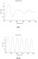
- Fig. 3 illustrates prior art detection of retardation using greyscale images. Values of less than 0.3 of the maximum intensity cannot occur for retardation values greater than 275nm (cf those for a typical stenter manufactured film are 800nm+). If 0.3 is set as the production specification for an authentic polymeric film greyscale analysis authenticates this result and as such have found utility in small devices such as the handheld and desktop authentication units.
- RGB channels can have their integrated retardation graphs calculated in the same way (except that there no longer exists a flat source for original Intensity (I o )).
- ⁇ is the wavelength
- R is the retardation (nm)
- I o is the intensity of the original light source.
- Figure 2 shows the integrated result for a white light source (400 - 700nm); this simulates the readings expected from a non-discriminating detector such as a photodiode that detects only intensity.
- Fig. 4(a) - (c) shows this for typical red (660nm ⁇ 20nm, green (550nm ⁇ 20nm) and blue (460nm ⁇ ) light sources.
- Processor 104 receives three output measurement signals from detectors 116, which may be characterised as R ⁇ G, R ⁇ B and B ⁇ G - that is to say the difference in retardation as between red, blue and green light from the respective light sources.
- Processor 104 calculates an authenticity result based on the algorithm:
- retardation is always less than 275nm and can be calculated by taking a mean of the RGB signal, subtracting the min (empty detector) and dividing the result by the max (1/2 wave value) minus min (empty detector).
- More sophisticated processing algorithms may allow the technique to be extended to substrates exhibiting retardation values of over 275nm. For example, comparison of the measured value for the red, green and blue channels may be made with expected values, and a calculation made to determine at which retardation they are least different.
- the difference between a hypothetical pixel value and the intensity expected for the colour channel may be calculated using a root-mean-square method. Calculated for each channel, where pixel is a pixel level (0 - 255), Icolour is an expected value for the channel at a retardation, r.
- Three 2D arrays of information may be stored in the processor of the apparatus for comparison.
- a second algorithm for retardation values greater than 275nm may be formulated as follows:
- Result is the answer, r is the retardation, RedArray, GreenArray and BlueArray are the ComparisonArrays for each channel, Red, Green and Blue are the measured results and Test is the sum of the differences between the measured results and the stored channels.
- This algorithm may be operated as a single loop to compare the total value of the differences between the measured RGB channels and their stored values.
- the difference for each channel is found by looking at each stored array, the address within the array is given by the coordinates of the retardation (r) and the measured pixel value for each channel.
- the Test value is then compared against a Result value that may initially be set at a high level; if the Test value is less than this, then Result is replaced by the Test value. So in real time the algorithm cycles through the retardations, sums them and tests them against a minimum value.
- the processor 104 after conducting such comparisons, is operative to instruct the alert system 106 to indicate that the film/item is authentic or non-authentic. If the result of the comparison is positive (i.e. the film is authentic), the processor is operative to send a signal to the alert system 106 containing an instruction to issue an indication that the film/item is authentic. Otherwise, the processor is operative to send a signal to the alert system 106 containing an instruction to issue an indication that the film/item is non-authentic.
Landscapes
- Physics & Mathematics (AREA)
- Health & Medical Sciences (AREA)
- General Health & Medical Sciences (AREA)
- Toxicology (AREA)
- General Physics & Mathematics (AREA)
- Spectroscopy & Molecular Physics (AREA)
- Engineering & Computer Science (AREA)
- Computer Vision & Pattern Recognition (AREA)
- Inspection Of Paper Currency And Valuable Securities (AREA)
- Investigating Or Analysing Materials By Optical Means (AREA)
- Polarising Elements (AREA)
- Credit Cards Or The Like (AREA)
Applications Claiming Priority (2)
| Application Number | Priority Date | Filing Date | Title |
|---|---|---|---|
| GB1512197.3A GB2540739A (en) | 2015-07-13 | 2015-07-13 | Authentication apparatus and method |
| PCT/GB2016/052101 WO2017009632A1 (en) | 2015-07-13 | 2016-07-12 | Authentication apparatus and method |
Publications (2)
| Publication Number | Publication Date |
|---|---|
| EP3323113A1 EP3323113A1 (en) | 2018-05-23 |
| EP3323113B1 true EP3323113B1 (en) | 2023-04-19 |
Family
ID=54013845
Family Applications (1)
| Application Number | Title | Priority Date | Filing Date |
|---|---|---|---|
| EP16741119.8A Active EP3323113B1 (en) | 2015-07-13 | 2016-07-12 | Authentication apparatus and method |
Country Status (8)
| Country | Link |
|---|---|
| US (1) | US20180293830A1 (pl) |
| EP (1) | EP3323113B1 (pl) |
| JP (1) | JP6631859B2 (pl) |
| KR (1) | KR102132890B1 (pl) |
| CN (1) | CN107636735B (pl) |
| GB (1) | GB2540739A (pl) |
| PL (1) | PL3323113T3 (pl) |
| WO (1) | WO2017009632A1 (pl) |
Families Citing this family (1)
| Publication number | Priority date | Publication date | Assignee | Title |
|---|---|---|---|---|
| EP3590073B1 (en) | 2017-03-01 | 2024-10-16 | Spectra Systems Corporation | Coded polymer substrates for banknote authentication |
Citations (1)
| Publication number | Priority date | Publication date | Assignee | Title |
|---|---|---|---|---|
| WO2014181086A1 (en) * | 2013-05-10 | 2014-11-13 | Innovia Films Limited | Authentication apparatus and method |
Family Cites Families (19)
| Publication number | Priority date | Publication date | Assignee | Title |
|---|---|---|---|---|
| GB2328180B (en) * | 1997-08-14 | 2001-08-01 | Thomas De La Rue Ltd | Security device |
| JP3709539B2 (ja) * | 1999-04-05 | 2005-10-26 | 独立行政法人 国立印刷局 | 真偽判別印刷物の機械的判別方法及びその装置 |
| JP2001126107A (ja) * | 1999-10-29 | 2001-05-11 | Nippon Conlux Co Ltd | 紙葉類の識別方法および装置 |
| JP2002055055A (ja) * | 1999-12-03 | 2002-02-20 | Sumitomo Osaka Cement Co Ltd | 複屈折性検査対象物の検査装置及び検査方法 |
| JP4011902B2 (ja) * | 2001-12-06 | 2007-11-21 | ユニオプト株式会社 | 波長依存性を考慮した複屈折測定装置及び方法 |
| JP2006510051A (ja) * | 2002-12-16 | 2006-03-23 | コーニンクレッカ フィリップス エレクトロニクス エヌ ヴィ | 光の偏光を用いる視覚暗号化を有する認証システム |
| CN101076714B (zh) * | 2004-10-25 | 2012-01-11 | 海因兹仪器公司 | 聚合物薄膜等的双折射测量 |
| JP2010072933A (ja) * | 2008-09-18 | 2010-04-02 | Toshiba Corp | 蛍光検知装置 |
| US8822954B2 (en) * | 2008-10-23 | 2014-09-02 | Intematix Corporation | Phosphor based authentication system |
| JP2010243363A (ja) * | 2009-04-07 | 2010-10-28 | Toshiba Corp | 蛍光検知装置 |
| WO2010150693A1 (ja) | 2009-06-25 | 2010-12-29 | チッソ株式会社 | 光配向した液晶性ポリイミドによる位相差膜及び光学素子 |
| JP2012181615A (ja) * | 2011-02-28 | 2012-09-20 | Tokyo Univ Of Agriculture & Technology | 情報保持媒体及び表示装置 |
| HK1198376A1 (en) * | 2011-09-26 | 2015-04-10 | Sicpa Holding Sa | Optically variable entity authenticating device and method |
| US9081147B2 (en) * | 2012-01-03 | 2015-07-14 | 3M Innovative Properties Company | Effective media retarder films with spatially selective birefringence reduction |
| US9053596B2 (en) * | 2012-07-31 | 2015-06-09 | De La Rue North America Inc. | Systems and methods for spectral authentication of a feature of a document |
| GB2506936A (en) * | 2012-10-15 | 2014-04-16 | Innovia Films Ltd | Birefringence authentication apparatus and method |
| JP6221738B2 (ja) * | 2013-01-07 | 2017-11-01 | セイコーエプソン株式会社 | 記録媒体判別装置および記録媒体判別方法 |
| CN103871151A (zh) * | 2014-03-11 | 2014-06-18 | 威海华菱光电股份有限公司 | 接触式图像检测装置及其应用方法 |
| WO2016009974A1 (ja) * | 2014-07-15 | 2016-01-21 | 富士フイルム株式会社 | 検知システムおよび検知方法 |
-
2015
- 2015-07-13 GB GB1512197.3A patent/GB2540739A/en not_active Withdrawn
-
2016
- 2016-07-12 EP EP16741119.8A patent/EP3323113B1/en active Active
- 2016-07-12 US US15/570,652 patent/US20180293830A1/en not_active Abandoned
- 2016-07-12 CN CN201680029974.XA patent/CN107636735B/zh active Active
- 2016-07-12 JP JP2018500883A patent/JP6631859B2/ja active Active
- 2016-07-12 PL PL16741119.8T patent/PL3323113T3/pl unknown
- 2016-07-12 KR KR1020187003143A patent/KR102132890B1/ko active Active
- 2016-07-12 WO PCT/GB2016/052101 patent/WO2017009632A1/en not_active Ceased
Patent Citations (1)
| Publication number | Priority date | Publication date | Assignee | Title |
|---|---|---|---|---|
| WO2014181086A1 (en) * | 2013-05-10 | 2014-11-13 | Innovia Films Limited | Authentication apparatus and method |
Also Published As
| Publication number | Publication date |
|---|---|
| PL3323113T3 (pl) | 2023-08-28 |
| JP2018522350A (ja) | 2018-08-09 |
| JP6631859B2 (ja) | 2020-01-15 |
| GB201512197D0 (en) | 2015-08-19 |
| CN107636735A (zh) | 2018-01-26 |
| CN107636735B (zh) | 2020-10-30 |
| WO2017009632A1 (en) | 2017-01-19 |
| US20180293830A1 (en) | 2018-10-11 |
| KR20180030069A (ko) | 2018-03-21 |
| HK1251705A1 (en) | 2019-02-01 |
| EP3323113A1 (en) | 2018-05-23 |
| KR102132890B1 (ko) | 2020-07-10 |
| GB2540739A (en) | 2017-02-01 |
Similar Documents
| Publication | Publication Date | Title |
|---|---|---|
| EP2311010B1 (en) | Authentication apparatus and methods | |
| AU2013331760B2 (en) | Authentication apparatus and method | |
| AU2014264400B2 (en) | Authentication apparatus and method | |
| FI85312B (fi) | Anordning foer granskning av sedlars autenticitet. | |
| US8766222B2 (en) | Method and apparatus for checking the usage state of documents of value | |
| EP3323113B1 (en) | Authentication apparatus and method | |
| US20190164372A1 (en) | Device and method for checking value documents, in particular banknotes, and value document processing system | |
| HK1251705B (en) | Authentication apparatus and method | |
| CA2555878A1 (en) | Method and device for the detection of counterfeit documents and banknotes | |
| CA2513798A1 (en) | Method for determining and/or verifying the contents of coin rolls | |
| CN119654662A (zh) | 用于检查具有至少一个能反射的安全元件的有价文件的传感器和方法 | |
| RU2442216C1 (ru) | Устройство для контроля элемента защиты объекта, меняющего яркость в зависимости от угла наблюдения, и способ контроля элемента защиты объекта, меняющего яркость в зависимости от угла наблюдения, с помощью этого устройства |
Legal Events
| Date | Code | Title | Description |
|---|---|---|---|
| STAA | Information on the status of an ep patent application or granted ep patent |
Free format text: STATUS: THE INTERNATIONAL PUBLICATION HAS BEEN MADE |
|
| PUAI | Public reference made under article 153(3) epc to a published international application that has entered the european phase |
Free format text: ORIGINAL CODE: 0009012 |
|
| STAA | Information on the status of an ep patent application or granted ep patent |
Free format text: STATUS: REQUEST FOR EXAMINATION WAS MADE |
|
| 17P | Request for examination filed |
Effective date: 20171110 |
|
| AK | Designated contracting states |
Kind code of ref document: A1 Designated state(s): AL AT BE BG CH CY CZ DE DK EE ES FI FR GB GR HR HU IE IS IT LI LT LU LV MC MK MT NL NO PL PT RO RS SE SI SK SM TR |
|
| AX | Request for extension of the european patent |
Extension state: BA ME |
|
| DAV | Request for validation of the european patent (deleted) | ||
| DAX | Request for extension of the european patent (deleted) | ||
| REG | Reference to a national code |
Ref country code: HK Ref legal event code: DE Ref document number: 1251705 Country of ref document: HK |
|
| STAA | Information on the status of an ep patent application or granted ep patent |
Free format text: STATUS: EXAMINATION IS IN PROGRESS |
|
| 17Q | First examination report despatched |
Effective date: 20210629 |
|
| REG | Reference to a national code |
Ref country code: DE Ref legal event code: R079 Ref document number: 602016078891 Country of ref document: DE Free format text: PREVIOUS MAIN CLASS: G07D0007120000 Ipc: G07D0007120500 |
|
| RIC1 | Information provided on ipc code assigned before grant |
Ipc: G07D 7/202 20160101ALI20220930BHEP Ipc: G07D 7/1205 20160101AFI20220930BHEP |
|
| R17C | First examination report despatched (corrected) |
Effective date: 20210629 |
|
| GRAP | Despatch of communication of intention to grant a patent |
Free format text: ORIGINAL CODE: EPIDOSNIGR1 |
|
| STAA | Information on the status of an ep patent application or granted ep patent |
Free format text: STATUS: GRANT OF PATENT IS INTENDED |
|
| INTG | Intention to grant announced |
Effective date: 20230113 |
|
| GRAS | Grant fee paid |
Free format text: ORIGINAL CODE: EPIDOSNIGR3 |
|
| GRAA | (expected) grant |
Free format text: ORIGINAL CODE: 0009210 |
|
| STAA | Information on the status of an ep patent application or granted ep patent |
Free format text: STATUS: THE PATENT HAS BEEN GRANTED |
|
| AK | Designated contracting states |
Kind code of ref document: B1 Designated state(s): AL AT BE BG CH CY CZ DE DK EE ES FI FR GB GR HR HU IE IS IT LI LT LU LV MC MK MT NL NO PL PT RO RS SE SI SK SM TR |
|
| REG | Reference to a national code |
Ref country code: GB Ref legal event code: FG4D |
|
| REG | Reference to a national code |
Ref country code: DE Ref legal event code: R096 Ref document number: 602016078891 Country of ref document: DE |
|
| REG | Reference to a national code |
Ref country code: CH Ref legal event code: EP |
|
| REG | Reference to a national code |
Ref country code: IE Ref legal event code: FG4D |
|
| REG | Reference to a national code |
Ref country code: AT Ref legal event code: REF Ref document number: 1561776 Country of ref document: AT Kind code of ref document: T Effective date: 20230515 |
|
| P01 | Opt-out of the competence of the unified patent court (upc) registered |
Effective date: 20230509 |
|
| REG | Reference to a national code |
Ref country code: LT Ref legal event code: MG9D |
|
| REG | Reference to a national code |
Ref country code: NL Ref legal event code: MP Effective date: 20230419 |
|
| REG | Reference to a national code |
Ref country code: AT Ref legal event code: MK05 Ref document number: 1561776 Country of ref document: AT Kind code of ref document: T Effective date: 20230419 |
|
| PG25 | Lapsed in a contracting state [announced via postgrant information from national office to epo] |
Ref country code: NL Free format text: LAPSE BECAUSE OF FAILURE TO SUBMIT A TRANSLATION OF THE DESCRIPTION OR TO PAY THE FEE WITHIN THE PRESCRIBED TIME-LIMIT Effective date: 20230419 |
|
| PG25 | Lapsed in a contracting state [announced via postgrant information from national office to epo] |
Ref country code: SE Free format text: LAPSE BECAUSE OF FAILURE TO SUBMIT A TRANSLATION OF THE DESCRIPTION OR TO PAY THE FEE WITHIN THE PRESCRIBED TIME-LIMIT Effective date: 20230419 Ref country code: PT Free format text: LAPSE BECAUSE OF FAILURE TO SUBMIT A TRANSLATION OF THE DESCRIPTION OR TO PAY THE FEE WITHIN THE PRESCRIBED TIME-LIMIT Effective date: 20230821 Ref country code: NO Free format text: LAPSE BECAUSE OF FAILURE TO SUBMIT A TRANSLATION OF THE DESCRIPTION OR TO PAY THE FEE WITHIN THE PRESCRIBED TIME-LIMIT Effective date: 20230719 Ref country code: ES Free format text: LAPSE BECAUSE OF FAILURE TO SUBMIT A TRANSLATION OF THE DESCRIPTION OR TO PAY THE FEE WITHIN THE PRESCRIBED TIME-LIMIT Effective date: 20230419 Ref country code: AT Free format text: LAPSE BECAUSE OF FAILURE TO SUBMIT A TRANSLATION OF THE DESCRIPTION OR TO PAY THE FEE WITHIN THE PRESCRIBED TIME-LIMIT Effective date: 20230419 |
|
| PG25 | Lapsed in a contracting state [announced via postgrant information from national office to epo] |
Ref country code: RS Free format text: LAPSE BECAUSE OF FAILURE TO SUBMIT A TRANSLATION OF THE DESCRIPTION OR TO PAY THE FEE WITHIN THE PRESCRIBED TIME-LIMIT Effective date: 20230419 Ref country code: LV Free format text: LAPSE BECAUSE OF FAILURE TO SUBMIT A TRANSLATION OF THE DESCRIPTION OR TO PAY THE FEE WITHIN THE PRESCRIBED TIME-LIMIT Effective date: 20230419 Ref country code: LT Free format text: LAPSE BECAUSE OF FAILURE TO SUBMIT A TRANSLATION OF THE DESCRIPTION OR TO PAY THE FEE WITHIN THE PRESCRIBED TIME-LIMIT Effective date: 20230419 Ref country code: IS Free format text: LAPSE BECAUSE OF FAILURE TO SUBMIT A TRANSLATION OF THE DESCRIPTION OR TO PAY THE FEE WITHIN THE PRESCRIBED TIME-LIMIT Effective date: 20230819 Ref country code: HR Free format text: LAPSE BECAUSE OF FAILURE TO SUBMIT A TRANSLATION OF THE DESCRIPTION OR TO PAY THE FEE WITHIN THE PRESCRIBED TIME-LIMIT Effective date: 20230419 Ref country code: GR Free format text: LAPSE BECAUSE OF FAILURE TO SUBMIT A TRANSLATION OF THE DESCRIPTION OR TO PAY THE FEE WITHIN THE PRESCRIBED TIME-LIMIT Effective date: 20230720 Ref country code: AL Free format text: LAPSE BECAUSE OF FAILURE TO SUBMIT A TRANSLATION OF THE DESCRIPTION OR TO PAY THE FEE WITHIN THE PRESCRIBED TIME-LIMIT Effective date: 20230419 |
|
| PG25 | Lapsed in a contracting state [announced via postgrant information from national office to epo] |
Ref country code: FI Free format text: LAPSE BECAUSE OF FAILURE TO SUBMIT A TRANSLATION OF THE DESCRIPTION OR TO PAY THE FEE WITHIN THE PRESCRIBED TIME-LIMIT Effective date: 20230419 |
|
| PG25 | Lapsed in a contracting state [announced via postgrant information from national office to epo] |
Ref country code: SK Free format text: LAPSE BECAUSE OF FAILURE TO SUBMIT A TRANSLATION OF THE DESCRIPTION OR TO PAY THE FEE WITHIN THE PRESCRIBED TIME-LIMIT Effective date: 20230419 |
|
| REG | Reference to a national code |
Ref country code: DE Ref legal event code: R097 Ref document number: 602016078891 Country of ref document: DE |
|
| PG25 | Lapsed in a contracting state [announced via postgrant information from national office to epo] |
Ref country code: SM Free format text: LAPSE BECAUSE OF FAILURE TO SUBMIT A TRANSLATION OF THE DESCRIPTION OR TO PAY THE FEE WITHIN THE PRESCRIBED TIME-LIMIT Effective date: 20230419 Ref country code: SK Free format text: LAPSE BECAUSE OF FAILURE TO SUBMIT A TRANSLATION OF THE DESCRIPTION OR TO PAY THE FEE WITHIN THE PRESCRIBED TIME-LIMIT Effective date: 20230419 Ref country code: EE Free format text: LAPSE BECAUSE OF FAILURE TO SUBMIT A TRANSLATION OF THE DESCRIPTION OR TO PAY THE FEE WITHIN THE PRESCRIBED TIME-LIMIT Effective date: 20230419 Ref country code: DK Free format text: LAPSE BECAUSE OF FAILURE TO SUBMIT A TRANSLATION OF THE DESCRIPTION OR TO PAY THE FEE WITHIN THE PRESCRIBED TIME-LIMIT Effective date: 20230419 Ref country code: CZ Free format text: LAPSE BECAUSE OF FAILURE TO SUBMIT A TRANSLATION OF THE DESCRIPTION OR TO PAY THE FEE WITHIN THE PRESCRIBED TIME-LIMIT Effective date: 20230419 |
|
| PLBE | No opposition filed within time limit |
Free format text: ORIGINAL CODE: 0009261 |
|
| STAA | Information on the status of an ep patent application or granted ep patent |
Free format text: STATUS: NO OPPOSITION FILED WITHIN TIME LIMIT |
|
| PG25 | Lapsed in a contracting state [announced via postgrant information from national office to epo] |
Ref country code: MC Free format text: LAPSE BECAUSE OF FAILURE TO SUBMIT A TRANSLATION OF THE DESCRIPTION OR TO PAY THE FEE WITHIN THE PRESCRIBED TIME-LIMIT Effective date: 20230419 |
|
| PG25 | Lapsed in a contracting state [announced via postgrant information from national office to epo] |
Ref country code: MC Free format text: LAPSE BECAUSE OF FAILURE TO SUBMIT A TRANSLATION OF THE DESCRIPTION OR TO PAY THE FEE WITHIN THE PRESCRIBED TIME-LIMIT Effective date: 20230419 |
|
| REG | Reference to a national code |
Ref country code: BE Ref legal event code: MM Effective date: 20230731 |
|
| PG25 | Lapsed in a contracting state [announced via postgrant information from national office to epo] |
Ref country code: LU Free format text: LAPSE BECAUSE OF NON-PAYMENT OF DUE FEES Effective date: 20230712 |
|
| 26N | No opposition filed |
Effective date: 20240122 |
|
| PG25 | Lapsed in a contracting state [announced via postgrant information from national office to epo] |
Ref country code: LU Free format text: LAPSE BECAUSE OF NON-PAYMENT OF DUE FEES Effective date: 20230712 |
|
| REG | Reference to a national code |
Ref country code: IE Ref legal event code: MM4A |
|
| PG25 | Lapsed in a contracting state [announced via postgrant information from national office to epo] |
Ref country code: RO Free format text: LAPSE BECAUSE OF NON-PAYMENT OF DUE FEES Effective date: 20230419 |
|
| PG25 | Lapsed in a contracting state [announced via postgrant information from national office to epo] |
Ref country code: SI Free format text: LAPSE BECAUSE OF FAILURE TO SUBMIT A TRANSLATION OF THE DESCRIPTION OR TO PAY THE FEE WITHIN THE PRESCRIBED TIME-LIMIT Effective date: 20230419 |
|
| PG25 | Lapsed in a contracting state [announced via postgrant information from national office to epo] |
Ref country code: SI Free format text: LAPSE BECAUSE OF FAILURE TO SUBMIT A TRANSLATION OF THE DESCRIPTION OR TO PAY THE FEE WITHIN THE PRESCRIBED TIME-LIMIT Effective date: 20230419 Ref country code: IT Free format text: LAPSE BECAUSE OF FAILURE TO SUBMIT A TRANSLATION OF THE DESCRIPTION OR TO PAY THE FEE WITHIN THE PRESCRIBED TIME-LIMIT Effective date: 20230419 Ref country code: FR Free format text: LAPSE BECAUSE OF NON-PAYMENT OF DUE FEES Effective date: 20230731 Ref country code: BE Free format text: LAPSE BECAUSE OF NON-PAYMENT OF DUE FEES Effective date: 20230731 |
|
| PG25 | Lapsed in a contracting state [announced via postgrant information from national office to epo] |
Ref country code: IE Free format text: LAPSE BECAUSE OF NON-PAYMENT OF DUE FEES Effective date: 20230712 |
|
| PG25 | Lapsed in a contracting state [announced via postgrant information from national office to epo] |
Ref country code: IE Free format text: LAPSE BECAUSE OF NON-PAYMENT OF DUE FEES Effective date: 20230712 |
|
| PG25 | Lapsed in a contracting state [announced via postgrant information from national office to epo] |
Ref country code: BG Free format text: LAPSE BECAUSE OF FAILURE TO SUBMIT A TRANSLATION OF THE DESCRIPTION OR TO PAY THE FEE WITHIN THE PRESCRIBED TIME-LIMIT Effective date: 20230419 |
|
| PG25 | Lapsed in a contracting state [announced via postgrant information from national office to epo] |
Ref country code: BG Free format text: LAPSE BECAUSE OF FAILURE TO SUBMIT A TRANSLATION OF THE DESCRIPTION OR TO PAY THE FEE WITHIN THE PRESCRIBED TIME-LIMIT Effective date: 20230419 |
|
| PGFP | Annual fee paid to national office [announced via postgrant information from national office to epo] |
Ref country code: PL Payment date: 20250613 Year of fee payment: 10 |
|
| PGFP | Annual fee paid to national office [announced via postgrant information from national office to epo] |
Ref country code: RO Payment date: 20250625 Year of fee payment: 10 |
|
| PG25 | Lapsed in a contracting state [announced via postgrant information from national office to epo] |
Ref country code: CY Free format text: LAPSE BECAUSE OF FAILURE TO SUBMIT A TRANSLATION OF THE DESCRIPTION OR TO PAY THE FEE WITHIN THE PRESCRIBED TIME-LIMIT; INVALID AB INITIO Effective date: 20160712 |
|
| PG25 | Lapsed in a contracting state [announced via postgrant information from national office to epo] |
Ref country code: HU Free format text: LAPSE BECAUSE OF FAILURE TO SUBMIT A TRANSLATION OF THE DESCRIPTION OR TO PAY THE FEE WITHIN THE PRESCRIBED TIME-LIMIT; INVALID AB INITIO Effective date: 20160712 |
|
| PGFP | Annual fee paid to national office [announced via postgrant information from national office to epo] |
Ref country code: DE Payment date: 20250721 Year of fee payment: 10 |
|
| PGFP | Annual fee paid to national office [announced via postgrant information from national office to epo] |
Ref country code: GB Payment date: 20250721 Year of fee payment: 10 |
|
| PGFP | Annual fee paid to national office [announced via postgrant information from national office to epo] |
Ref country code: CH Payment date: 20250801 Year of fee payment: 10 |
|
| PG25 | Lapsed in a contracting state [announced via postgrant information from national office to epo] |
Ref country code: TR Free format text: LAPSE BECAUSE OF FAILURE TO SUBMIT A TRANSLATION OF THE DESCRIPTION OR TO PAY THE FEE WITHIN THE PRESCRIBED TIME-LIMIT Effective date: 20230419 |