EP3323155B1 - Échangeur de chaleur thermoélectrique - Google Patents
Échangeur de chaleur thermoélectrique Download PDFInfo
- Publication number
- EP3323155B1 EP3323155B1 EP16731112.5A EP16731112A EP3323155B1 EP 3323155 B1 EP3323155 B1 EP 3323155B1 EP 16731112 A EP16731112 A EP 16731112A EP 3323155 B1 EP3323155 B1 EP 3323155B1
- Authority
- EP
- European Patent Office
- Prior art keywords
- heat exchanger
- fluid
- semiconductors
- elements
- electrically
- Prior art date
- Legal status (The legal status is an assumption and is not a legal conclusion. Google has not performed a legal analysis and makes no representation as to the accuracy of the status listed.)
- Not-in-force
Links
Images


Classifications
-
- H—ELECTRICITY
- H10—SEMICONDUCTOR DEVICES; ELECTRIC SOLID-STATE DEVICES NOT OTHERWISE PROVIDED FOR
- H10N—ELECTRIC SOLID-STATE DEVICES NOT OTHERWISE PROVIDED FOR
- H10N10/00—Thermoelectric devices comprising a junction of dissimilar materials, i.e. devices exhibiting Seebeck or Peltier effects
- H10N10/10—Thermoelectric devices comprising a junction of dissimilar materials, i.e. devices exhibiting Seebeck or Peltier effects operating with only the Peltier or Seebeck effects
- H10N10/13—Thermoelectric devices comprising a junction of dissimilar materials, i.e. devices exhibiting Seebeck or Peltier effects operating with only the Peltier or Seebeck effects characterised by the heat-exchanging means at the junction
-
- F—MECHANICAL ENGINEERING; LIGHTING; HEATING; WEAPONS; BLASTING
- F01—MACHINES OR ENGINES IN GENERAL; ENGINE PLANTS IN GENERAL; STEAM ENGINES
- F01N—GAS-FLOW SILENCERS OR EXHAUST APPARATUS FOR MACHINES OR ENGINES IN GENERAL; GAS-FLOW SILENCERS OR EXHAUST APPARATUS FOR INTERNAL-COMBUSTION ENGINES
- F01N5/00—Exhaust or silencing apparatus combined or associated with devices profiting by exhaust energy
- F01N5/02—Exhaust or silencing apparatus combined or associated with devices profiting by exhaust energy the devices using heat
- F01N5/025—Exhaust or silencing apparatus combined or associated with devices profiting by exhaust energy the devices using heat the device being thermoelectric generators
-
- F—MECHANICAL ENGINEERING; LIGHTING; HEATING; WEAPONS; BLASTING
- F25—REFRIGERATION OR COOLING; COMBINED HEATING AND REFRIGERATION SYSTEMS; HEAT PUMP SYSTEMS; MANUFACTURE OR STORAGE OF ICE; LIQUEFACTION SOLIDIFICATION OF GASES
- F25B—REFRIGERATION MACHINES, PLANTS OR SYSTEMS; COMBINED HEATING AND REFRIGERATION SYSTEMS; HEAT PUMP SYSTEMS
- F25B21/00—Machines, plants or systems, using electric or magnetic effects
- F25B21/02—Machines, plants or systems, using electric or magnetic effects using Peltier effect; using Nernst-Ettinghausen effect
- F25B21/04—Machines, plants or systems, using electric or magnetic effects using Peltier effect; using Nernst-Ettinghausen effect reversible
-
- H—ELECTRICITY
- H10—SEMICONDUCTOR DEVICES; ELECTRIC SOLID-STATE DEVICES NOT OTHERWISE PROVIDED FOR
- H10N—ELECTRIC SOLID-STATE DEVICES NOT OTHERWISE PROVIDED FOR
- H10N10/00—Thermoelectric devices comprising a junction of dissimilar materials, i.e. devices exhibiting Seebeck or Peltier effects
- H10N10/01—Manufacture or treatment
-
- H—ELECTRICITY
- H10—SEMICONDUCTOR DEVICES; ELECTRIC SOLID-STATE DEVICES NOT OTHERWISE PROVIDED FOR
- H10N—ELECTRIC SOLID-STATE DEVICES NOT OTHERWISE PROVIDED FOR
- H10N10/00—Thermoelectric devices comprising a junction of dissimilar materials, i.e. devices exhibiting Seebeck or Peltier effects
- H10N10/10—Thermoelectric devices comprising a junction of dissimilar materials, i.e. devices exhibiting Seebeck or Peltier effects operating with only the Peltier or Seebeck effects
- H10N10/17—Thermoelectric devices comprising a junction of dissimilar materials, i.e. devices exhibiting Seebeck or Peltier effects operating with only the Peltier or Seebeck effects characterised by the structure or configuration of the cell or thermocouple forming the device
Definitions
- the present invention relates to a thermoelectric heat exchanger for controlling the temperature of a fluid, in particular for a motor vehicle, with a Peltier element.
- the invention further relates to such a Peltier element.
- heat exchangers For tempering fluids, in particular gases, usually heat exchangers are used. Such heat exchangers allow this to heat the fluid and / or to cool. For this purpose, such heat exchangers can have tempering elements.
- Such a heating element is from the WO 92/06570 A known.
- the heating element is designed here as a PTC thermistor or a positive temperature coefficient heating element (PTC heating element) and is used for heating an air flow.
- a disadvantage of such dissipative heating elements is that they do not allow sufficient heating and / or have too high a consumption of resources, in particular with low available electrical resources.
- thermoelectric temperature control elements for controlling the temperature of a fluid.
- the use of such a thermoelectric heating element in a heat exchanger is known from DE 10 2009 058 673 A1 and the EP 2 518 424 A1 known.
- each one Peltier element is used, which has a cold side and a warm side by a corresponding circuit and installation of an electrical voltage.
- a corresponding arrangement of the Peltier element makes it possible, apart from the heat transfer between the fluid and another fluid caused by the temperature difference, to realize a heat transfer achieved by the Peltier element, so that the total heat transfer is increased.
- Such Peltier elements have a plurality of differently doped semiconductors, which are interconnected.
- the semiconductors are electrically insulated on both sides by an electrically insulating coating and / or an electrically insulating plate.
- Such electrical insulation is regularly a thermal barrier, which deteriorates a thermal exchange of the Peltier element.
- the electrical insulations are disposed on the opposite sides of the Peltier element in the heat flow direction, the heat exchange between the Peltier element and the fluid or article to be tempered is made more difficult.
- Such Peltier elements are also rigid. During operation of the Peltier element, a temperature difference occurs within the Peltier element, which leads to thermal stresses within the Peltier element. These thermal stresses can lead to damage to the electrical insulation of the Peltier element, as well as to damage the electrical connections between the semiconductors, which adversely affect the function of the Peltier element, in particular lead to failure of the Peltier element can.
- US 2007/0220902 A1 shows a heat exchanger with a Peltier element wherein the Peltier element has a first carrier for supporting semiconductors of the Peltier element.
- the Peltier element also has a second carrier and a third carrier, wherein in these carriers heat exchange elements are held, which are contacted in each case via electrodes electrically connected to the semiconductors.
- the present invention therefore deals with the problem of providing a Peltier element having a thermoelectric heat exchanger for controlling the temperature of a fluid as well as for such a Peltier element an improved or at least to provide other embodiment, which is characterized in particular by improved efficiency and / or durability.
- the present invention is based on the general idea, in a Peltier element having a thermoelectric heat exchanger for controlling a fluid flowing through a flow space, at least one semiconductor of the Peltier element electrically connecting conductor at least partially in the flow space to order, so that in particular the flowing fluid directly exposed.
- This allows the conductor to be used both for electrically connecting the semiconductors and for heat exchange between the fluid and the Peltier element.
- the thermoelectric heat exchanger thus has the flow space through which the fluid to be tempered can flow.
- the Peltier element is used for tempering the fluid and has a plurality of alternately arranged p-type P-type semiconductor and n-type N-type semiconductor.
- the electrical connection of the semiconductor takes place by said conductors, which are realized by a connection structure and a contacting structure.
- the semiconductors are electrically contacted on their side facing the flow space by the connecting structure and are electrically contacted on their side remote from the flow space by the contacting structure.
- the connecting structure has connecting elements which each electrically contact two such semiconductors and are electrically insulated from one another.
- the contacting structure has for electrically contacting the semiconductor contact elements, which each contact two such semiconductor electrically and are mutually electrically insulated. It is provided according to the invention that at least one such connecting element is arranged in the flow space.
- the semiconductors of the Peltier element are preferably connected in series by means of the connection structure and the contacting structure. However, it is also conceivable to switch at least two of the semiconductors in parallel.
- the solution according to the invention makes it possible to dispense with an electrically insulating layer and / or an electrically insulating plate on the side of the Peltier element facing the flow space, with preferred variants being formed without such an electrically insulating layer or plate.
- a thermal barrier between the Peltier element and the fluid caused by such an electrically insulating layer or plate is considerably reduced, resulting in improved heat exchange between the fluid and the Peltier element and thus improved efficiency of the heat exchanger .
- the absence of such insulating layers leads to a simplified and more cost-effective production of the Peltier element or the heat exchanger. In addition, this can reduce the weight of the Peltier element or the heat exchange.
- the heat exchanger according to the invention can be used in any application for controlling the temperature of such a fluid. It is conceivable, in particular, to use the heat exchanger in a motor vehicle in order to temper a fluid flowing through the motor vehicle. In particular, it is conceivable to use the heat exchanger as a heater, for example additional heater, for controlling the temperature of the fluid.
- the fluid may in particular be air, which is supplied to an interior of the motor vehicle. Consequently, the heat exchanger is used as an air conditioning device of the motor vehicle or as part of such an air conditioning device.
- the fluid to be tempered is advantageously electrically non-conductive.
- the fluid to be tempered if it is gaseous, in particular the air to be tempered, should not exceed a predetermined moisture content.
- a liquid flowing through the flow space can be tempered, in particular if the liquid is electrically non-conductive or if the liquid does not exceed a predetermined electrical conductivity.
- connection elements and at least one of the associated semiconductors are preferably fastened to one another.
- the respective connecting element is fastened to both associated semiconductors are advantageous.
- the attachment is advantageously realized by soldering the connection element to at least one of the associated semiconductors.
- Preferred variants provide that at least one such connecting element is arranged directly in the flow space.
- the connecting element has no additional electrical insulation at least in the flow space and / or is surrounded by no additional electrical insulation. This can result in an immediate contact and heat exchange between the connecting element and the fluid, whereby the efficiency of the heat exchanger is further improved. It is particularly preferred in this case if the connecting element is in heat-exchanging contact both with the fluid and with the associated semiconductors.
- At least one such connecting element is exposed to the flow of the fluid flowing through the flow space. That is, the fluid flows in operation of the heat exchanger along the connecting element and / or around the connecting element. As a result, the heat exchange between the fluid and the connecting element and thus between the fluid and the Peltier element is improved, thereby increasing the efficiency of the heat exchanger.
- the heat exchanger has a fluid channel through which a tempering fluid can flow, wherein the fluid channel is fluidically separated from the flow space.
- the fluid channel is also arranged on the side facing away from the flow space side of the semiconductor, which are electrically isolated from the tempering fluid.
- the tempering fluid is also used to control the temperature of the fluid.
- the fluid channel facing side of the Peltier element is a cold side of the Peltier element.
- the flow space facing side of the Peltier element is a hot side of the Peltier element, so that the total heat transfer to the fluid from the heat transfer of Temperierfluids and the Peltier element composed.
- the heat exchanger is preferably used for heating the fluid.
- the realization of the cold side and the warm side of the Peltier element can be done by applying a corresponding electrical voltage to the Peltier element.
- a reversal of the cold side and the warm side of the Peltier element can be realized by another, in particular reversed, installation of the electrical voltage to the Peltier element, in particular to cool the fluid.
- the tempering fluid may be any fluid.
- the tempering fluid may in particular be a liquid.
- the tempering fluid may in particular be cooling water of the motor vehicle, which is used in the heat exchanger for heating the fluid and thereby cooled.
- the fluid channel can in principle run arbitrarily, provided that a heat exchange between the fluid and the tempering fluid, in particular via the Peltier element, is possible. It is conceivable in particular that the fluid channel runs along the flow space.
- connection element protrudes into the flow space. That means in particular in that the connecting element has at least one section which protrudes from at least one of the associated semiconductors in the flow space. As a result, in particular, a surface of the connecting element for heat exchange with the fluid is increased and thus the heat exchange with the fluid is improved.
- At least one such connecting element can be flowed through by the fluid to be tempered.
- a heat exchange between the connecting element and the fluid can be improved and the efficiency of the heat exchanger can thus be increased.
- connection structure can be a heat exchange structure, for example a rib structure, with which both an electrical connection between the semiconductors and a heat exchange takes place between the semiconductors and the fluid.
- the components of the heat exchanger can be reduced, so that the heat exchanger is easier and / or less expensive to produce overall.
- the heat exchange between the Peltier element and the fluid is improved, thereby increasing the efficiency of the heat exchanger.
- the respective connecting element can in principle have any shape, provided that it electrically connects two such semiconductors and is arranged at least partially in the flow space.
- connection element lies flat against at least one of the associated semiconductors.
- the heat transferring area between the connecting member and the at least one associated semiconductor is increased and thus the heat exchange is improved.
- the planar contact of the connecting element on at least one of the associated semiconductors is advantageously realized on the side of the at least one semiconductor facing the flow space. This means that the connecting element lies flat against the at least one semiconductor on the side of the at least one semiconductor facing the flow space.
- the electrical insulation of the connecting elements against each other can be realized in any manner.
- connection elements spaced from each other in order to isolate them against each other electrically.
- the spaced arrangement of the connecting elements also has the advantage that the connecting elements are movable relative to each other, so that they can break down in particular thermal stresses. As a result, therefore, corresponding damage to the Peltier element is avoided or at least reduced and thus improves the resistance of the heat exchanger.
- the insulating portion is designed to compensate for thermal stresses elastic. Also, this can increase the durability of the heat exchanger.
- the insulating section can be made in principle of any material, provided that it electrically isolates the associated connecting elements. It is conceivable, in particular, to produce such an insulating section made of plastic, in particular of a polymer. In this way, the respective insulating section and thus the heat exchanger can be easily and inexpensively manufactured. In addition, it is possible to realize in addition to the electrical insulation said elastic formation of the insulating portion to compensate for thermal stresses.
- connecting element is designed to be elastic for compensating thermal stresses.
- the elastic design of the connecting element can be realized by a corresponding material selection of the connecting element and / or by a corresponding shape of the connecting element.
- the respective connecting element can in principle be made of any material, as long as it electrically connects two such semiconductors.
- the connecting element is made of a metal or metal-containing material. As a result, both a sufficient electrical conductivity of the connecting element and an improved heat exchange of the connecting element is given.
- At least two such connecting elements are formed as equal parts in order to simplify the production of the heat exchanger and / or to allow a cost-effective production of the heat exchanger.
- the heat exchange between the tempering fluid or the fluid channel and the Peltier element can also be realized via at least one such contact element.
- at least one such contact element in an analogous manner to at least one such connecting element in the fluid channel, so that there is a, in particular direct, heat exchange between the contact element and the tempering.
- the tempering fluid is not electrically conductive, electrical isolation of the semiconductors relative to the tempering fluid is not absolutely necessary. If the tempering fluid is electrically conductive, the semiconductors are preferably insulated from the tempering fluid.
- the semiconductors are preferably insulated from the fluid channel when the fluid channel is made of an electrically conductive material. In contrast, such insulation can be omitted, if the fluid channel is made of an electrically non-conductive material or an electrically insulating material.
- the electrical insulation of the tempering compared to the semiconductors can be realized in any way. It is conceivable, for example, the fluid channel made of an electrically insulating material, for example made of plastic.
- an electrically insulating insulating layer between at least one such semiconductor and the fluid channel, in particular between at least one such contact element and the fluid channel.
- the use of such an insulating layer makes it possible to use such a fluid channel, which is electrically conductive, in particular made of a metal.
- the use of a metallic or metal-containing material for the fluid channel in this case increases the heat exchange between the tempering fluid and the at least one contact element, whereby the efficiency of the heat exchanger is increased.
- At least one such contact element is arranged on the flow space facing side of the fluid channel and secured to the fluid channel.
- Such an attachment can be rigid, in particular because the compensation of thermal stresses can be realized on the part of the connection structure.
- the insulating layer between the contact element and the fluid channel may be made of any material.
- the insulating layer may in particular be a dielectric, preferably a ceramic.
- the ceramic is designed such that it ensures a sufficient heat exchange between the fluid channel or the tempering fluid and the Peltier element.
- the heat exchanger can also have two or more such Peltier elements. It is conceivable, in particular, to arrange two such Peltier elements opposite one another, wherein at least one of the Peltier elements has such a connection structure with at least one such connecting element arranged in the flow space. It is also to be considered in embodiments in which at least two such Peltier elements are arranged side by side.
- the heat exchanger has two or more such Peltier elements, it is possible to electrically connect at least two such Peltier elements, in particular to connect in series.
- At least one such semiconductor of the Peltier element can have two or more semiconductor elements that are similarly doped. That is, at least one such P-type semiconductor may have two or more P-type P-type semiconductor elements. Accordingly, at least one such N-type semiconductor may have at least two N-type N-type semiconductor elements.
- thermoelectric heat exchanger 1 of an otherwise not shown motor vehicle 2 is shown.
- the heat exchanger 1 has a flow space 3 through which a fluid can flow.
- the heat exchanger 1 also has a Peltier element 4 which has a multiplicity of p-doped P-type semiconductors 5 and n-doped N-type semiconductors 6 arranged alternately along the flow space 3.
- the semiconductors 5, 6 are electrically contacted with one another on their side facing the flow space 3 by means of a connecting structure 7 and on their side remote from the flow space 3 by means of a contacting structure 8 and thus connected in series.
- the connecting structure 7 has a plurality of connecting elements 9, wherein the respective connecting element 9 electrically contacts such a P-semiconductor 5 with the adjacent N-semiconductor 6.
- the connecting elements 9 are electrically insulated from each other.
- the associated semiconductors 5, 6 electrically connecting connecting elements 9 are further arranged in the flow space 3. This results in a heat exchange between the connecting elements 9 and the fluid flowing through the flow space 3, so that a temperature control of the fluid by means of the Peltier element 4 is improved and the efficiency of the heat exchanger 1 is increased.
- the sides of the semiconductors 5, 6 facing the flow space 3 form a first temperature side 10 of the Peltier element 4, whereas the sides of the semiconductors 5, 6 facing away from the flow space 3 form a second temperature side 11 of the Peltier element 4.
- the first temperature side 10 corresponds to a hot side 10 'of the Peltier element 4
- the second temperature side 11 corresponds to a cold side 11' of the Peltier element 4. That means that the Warm side 10 'of the Peltier element 4 in the operation of the Peltier element 4 has a higher temperature than the cold side 11'.
- the fluid flowing through the flow space 3 can be heated by means of the Peltier element 4.
- the connecting elements 9 communicate with the associated semiconductors 5, 6 in heat-transmitting connection, so that they exchange heat on the one hand with the fluid flowing through the flow space 3 and on the other hand with the associated semiconductors 5, 6. This results in an improved heat exchange between the Peltier element 4 and the fluid, in particular because an electrical insulation of the Peltier element 4 on the flow space 3 facing side of the Peltier element 4 and thus a corresponding thermal barrier can be omitted.
- the respective connecting element 9 is designed in the manner of a rib 12, which provides an enlarged surface for heat exchange with the fluid. That is, the connection structure 7 is formed as a rib structure 13.
- the connecting structure 7 is further made of a metallic material, in particular of a metal sheet 14, in order to reduce the manufacturing costs of the heat exchanger 1.
- the connecting elements 9 have no electrically insulating coating, so that they are in direct contact with the fluid and are accordingly designed as heat exchange elements 15. This results in an immediate heat exchange between the connecting elements 9 and the fluid, whereby the efficiency of the heat exchanger 1 is increased.
- the respective connecting element 9 is formed symmetrically in the example shown and the view shown and has a base side 16 projecting from the opposite sides to each other inclined leg 17, of which in turn directed away from each other, parallel to the base side 16 extending feet 18. This results in a total of an omega-like shape of the respective connecting element 9.
- the respective connecting element 9 is located on the base side 16 surface on both associated semiconductors 5, 6 at. Thereby, an area for heat exchange between the connecting element 9 and the associated semiconductors 5, 6 is increased. Thus, therefore, the heat exchange between the semiconductors 5, 6 and the connecting elements 9 and thus between the Peltier element 4 and the fluid is improved.
- connection structure 7 is interrupted in the area of the feet 18.
- an insulating section 19 can be arranged between adjacent connecting elements 9, which electrically isolates and mechanically connects the connecting elements 9.
- Fig. 1 are two such insulating portions 19 can be seen, each electrically isolate two adjacent connecting elements 9 and mechanically connect.
- the insulating portions 19 are arranged in the example shown between adjacent feet 18 of the adjacent connecting elements 9 and connect these feet 18 mechanically.
- the insulating portions 19 are advantageously made of plastic, in particular of a polymer.
- the fluid flowing through the flow space 3 is preferably such a fluid that is not electrically conductive.
- the fluid should, if it is gaseous, not exceed a predetermined moisture content.
- the heat exchanger 1 may have a dehumidifying device (not shown here and arranged upstream of the Peltier element 4 in the flow direction of the fluid) for dehumidifying the fluid.
- the connecting elements 9 are arranged by their shape in the flow space 3 and are in the flow space 3 from.
- the connecting elements 9 can be flowed through by the fluid.
- a larger area of the respective connecting element 9 is flowed by the fluid and / or flows around, so that there is an improved heat exchange between the connecting elements 9 and the fluid.
- the connecting structure 7, in particular the connecting elements 9, are designed to be elastic in order to reduce thermal stresses within the Peltier element 4.
- the elastic design of the connecting elements 9 is given here by the corresponding objectionable arrangement of the connecting elements 9 and / or their shape.
- the insulating portions 19 are designed to reduce thermal stress elastic. As a result, a total of relative movement between the connecting elements 9 is possible to reduce said thermal stresses.
- the connecting elements 9 are attached to the associated semiconductors 5, 6.
- the attachment is realized in the example shown on the bases 16 and can be made rigid, since the thermal compensation over the legs 17 and feet 18 of the connecting elements 9 can be done. In this case, it is conceivable, in particular, to solder the connecting elements 9 to the associated semiconductors 5.
- the contact structure 8 for electrically contacting the semiconductors 5, 6 on the side remote from the flow space 3 has a plurality of contact elements 20, the respective contact element 20 electrically contacting such an N-type semiconductor 6 with such a P-type semiconductor 5.
- the contact elements 20 are arranged spaced from each other and thus electrically isolated from each other.
- the contact elements 20 are formed as conductor bridges 21, which run flat and are made of a metallic or metal-containing material and extend flat. The contact elements 20 are further soldered to the associated semiconductors 5, 6.
- the flow space 3 is bounded on the side facing away from the contacting structure 8 side of the feet 18 by a wall 22 which may be part of a housing 23.
- the heat exchanger 1 has a fluid channel 24 extending along the flow space 3, which is arranged on the side of the Peltier element 4 facing away from the wall 22.
- the fluid channel 24 can be flowed through by a tempering fluid, in particular by the cooling water of the motor vehicle 2.
- the tempering fluid is used to control the temperature of the fluid flowing through the flow space 3.
- the Peltier element 4 and the tempering fluid are preferably used for heating the fluid.
- the cold side 1 1 'of the Peltier element 4 the required heat from the tempering fluid and transmits this heat, due to the Peltier effect, reinforced to the fluid, thereby said "pumping" the heat is realized.
- the tempering fluid preferably has a higher temperature than the fluid.
- the fluid channel 24 is formed as a tube 25.
- the tube 25 is made of a metallic or metal-containing material and thus electrically conductive.
- the Peltier element 4, in particular the semiconductors 5, 6, are electrically insulated from the fluid channel 24.
- an electrically insulating insulating layer 26 is provided between the semiconductors 5, 6 or the contact elements 20 and the fluid channel 24. It is conceivable in particular, the insulating layer 26 as an insulating plate 27, in particular a ceramic plate 27 ', form.
- the insulating layer 26 and the Peltier element 4, in particular the contacting structure 8, are fastened to one another via the contact elements 20, in particular glued together.
- the insulating layer 26 is mechanically connected to the fluid channel 24, in particular applied to the fluid channel 24.
- the Peltier element 4 is attached to the fluid channel 24.
- the fluid channel 24, in particular the tube 25, from an electrically insulating material, for example plastic.
- the insulating layer 26 can be omitted.
- Fig. 2 shows another embodiment of the heat exchanger 1.
- the in Fig. 2 shown heat exchanger 1 has two such Peltier elements 4, which are arranged symmetrically opposite.
- the Peltier elements 4 are arranged opposite one another such that the feet 18 of the associated connecting elements 9 of the connecting structures 7 are opposite.
- the flow space 3 is delimited on opposite sides by such a fluid channel 24 or such an insulating layer 26. That is, the heat exchanger 1 in Fig. 2 two such, opposite fluid channels 24, through which in each case a tempering fluid, in particular the same temperature fluid, for example cooling water of the associated motor vehicle 2, flows.
- heat is drawn off from the respective tempering fluid by means of the Peltier elements 4 and pumped to a higher level and supplied to the fluid.
- connection structures 7 are electrically insulated from one another. This is done by a spaced arrangement of the connecting elements 9 of the connecting structures 7. Alternatively or additionally, such an insulating portion 19 may be provided between the connecting elements. It is conceivable, as in Fig. 2 shown centrally, to electrically insulate adjacent connecting elements 9 of both Peltier elements 4 via such a common insulating section 19. It is also conceivable to provide in each case a separate such insulating section 19 in adjacently arranged connecting elements 9 of the Peltier elements 4.
- the Peltier elements 4 can, as indicated by a dashed line 28, be connected in series, in the example shown for this purpose an N-type semiconductor 6 of a Peltier element 4 with a P-type semiconductor 5 of the other Peltier element 4 in electrical Contact stands.
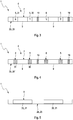
- Fig. 3 shows a section through such a Peltier element 4, wherein only the semiconductor 5, 6 and the connection structure 7 can be seen.
- the respective connecting element 9 is assigned such an N-type semiconductor 6 and such a P-type semiconductor 5.
- the connecting structure 7 and the connecting elements 9 from a band 29, in particular from an endless belt 29 ', wherein said belt 29 is fitted in corresponding sections with the semiconductors 5, 6 and separated into the respective connecting elements 9. In the areas of separation, such an insulating section 19 is subsequently provided. Subsequently, a deformation of the belt 29 and a separation of the belt 29, for example in the Fig. 1 and 2 shownieresbeitul done.
- the band 29 can first be provided with invisible recesses or interruptions. In these interruptions then optionally said insulating sections can be provided.
- the semiconductors 5, 6 are preferably provided by soldering the semiconductors 5, 6 to the band 29 or the connecting elements 9. It is also conceivable to first apply the semiconductors 5, 6 to a carrier, not shown, in particular the carrier to coat the semiconductors 5, 6, and to connect the carriers provided with the semiconductors 5, 6 with the band 29 or with the associated connecting elements 9.
- the respective semiconductor 5, 6 has a single semiconductor element 30, 31. That is, the P-type semiconductor 5 is a P-type P-type semiconductor element 30, whereas the N-type semiconductor 6 is an N-type N-type semiconductor element 31.
- Fig. 4 shows another embodiment of the Peltier element 4, which differs from the in Fig. 3 shown embodiment differs essentially in that the respective semiconductor 5, 6 has a plurality of such identically doped semiconductor elements 30, 31.
- the respective P-type semiconductor element 5 has a plurality of, in the example shown, nine, p-doped P-type semiconductor elements 30, while the respective N-type semiconductor 6 has a plurality, in the example shown, of nine N-type semiconductor elements 31.
- Fig. 5 shows a section through the heat exchanger 1, in which a plan view of the fluid channel 24 with the contacting structure 8 can be seen.
- the fluid channel 24 is provided with the contact elements 20 of the contacting structure 8, that is, the contact elements 20 are mounted and / or fixed to the fluid channel 24, wherein between the contact elements 20 and the fluid channel 24, if necessary, such an insulating layer 26 are provided can.
- the fluid channel 24 is provided with the contact elements 20, for example, by gluing the contact elements 20 to the fluid channel 24.
- the Peltier element 4 can be produced in that the connection structure 7 equipped with the semiconductors 5, 6 with the contact elements 20 and thus the Contact structure 8 are connected, in which the semiconductor 5, 6 electrically contacted with associated contact elements 20, in particular with the associated contact element 20 are soldered.
Landscapes
- Engineering & Computer Science (AREA)
- Mechanical Engineering (AREA)
- General Engineering & Computer Science (AREA)
- Manufacturing & Machinery (AREA)
- Chemical & Material Sciences (AREA)
- Combustion & Propulsion (AREA)
- Physics & Mathematics (AREA)
- Thermal Sciences (AREA)
- Air-Conditioning For Vehicles (AREA)
Claims (15)
- Procédé de production d'un élément à effet Peltier (4) d'un échangeur de chaleur (1) pour la régulation de température d'un fluide, qui présente un espace de circulation (3) pouvant être parcouru par le fluide à réguler en température, dans lequel- l'élément à effet Peltier (4) présente une pluralité de semi-conducteurs de type P (5) à dopage p et de semi-conducteurs de type N (6) à dopage n, agencés de manière alternée,- dans lequel les semi-conducteurs (5, 6) sont mis en contact électrique sur leur face tournée vers l'espace de circulation (3) grâce à une structure de liaison (7) qui présente des éléments de liaison (9) mettant en contact électrique respectivement deux semi-conducteurs (5, 6) desdits types,- dans lequel les éléments de liaison (9) sont isolés électriquement les uns des autres,- dans lequel les semi-conducteurs (5, 6) sont mis en contact électrique sur leur face détournée de l'espace de circulation (3) grâce à une structure de contact (8) qui présente des éléments de contact (20) mettant en contact électrique respectivement deux semi-conducteurs (5, 6) desdits types,- dans lequel les éléments de contact (20) sont isolés électriquement les uns des autres,- dans lequel au moins un élément de liaison (9) dudit type est agencé dans l'espace de circulation (3),caractérisé par les étapes de procédé consistant à :- fournir une bande électriquement conductrice (29),- munir de manière alternée la bande (29) de semi-conducteurs de type P (5) à dopage p et de semi-conducteurs de type N (6) à dopage n le long de la bande (29),- découper la bande (29) afin de produire les éléments de liaison (9) isolés électriquement les uns des autres.
- Procédé selon la revendication 1,
caractérisé en ce que
la bande (29) est transformée après avoir été munie des semi-conducteurs (5, 6) ou avant d'avoir été munie des semi-conducteurs (5, 6). - Échangeur de chaleur thermoélectrique (1) pour la régulation de température d'un fluide, en particulier pour un véhicule automobile (2),- avec un espace de circulation (3) pouvant être parcouru par le fluide à réguler en température,- avec un élément à effet Peltier (4) produit conformément au procédé selon la revendication 1 ou 2,- dans lequel au moins un élément de liaison (9) dudit type est agencé dans l'espace de circulation (3).
- Échangeur de chaleur selon la revendication 3,
caractérisé en ce que- l'échangeur de chaleur (1) présente un canal de fluide (24) pouvant être parcouru par un fluide à réguler en température, séparé fluidiquement de l'espace de circulation (3) et agencé du côté des semi-conducteurs (5, 6) qui est détourné de l'espace de circulation (3), et/ou- au moins un élément de liaison (9) dudit type fait saillie dans l'espace de circulation (3). - Échangeur de chaleur selon la revendication 3 ou 4,
caractérisé en ce que
au moins un élément de liaison (9) dudit type peut être parcouru par le fluide à réguler en température. - Échangeur de chaleur selon l'une quelconque des revendications 3 à 5,
caractérisé en ce que- au moins un élément de liaison (9) dudit type est réalisé sous forme d'un élément d'échange thermique (15) entre le fluide et les semi-conducteurs (5, 6) associés, et/ou- au moins un élément de liaison (9) dudit type est réalisé sous forme d'une nervure (12) faisant saillie dans l'espace de circulation (3). - Échangeur de chaleur selon l'une quelconque des revendications 3 à 6,
caractérisé en ce que
au moins un élément de liaison (9) dudit type repose à plat sur au moins un des semi-conducteurs (5, 6) associés. - Échangeur de chaleur selon l'une quelconque des revendications 3 à 7,
caractérisé en ce que
au moins deux desdits éléments de liaison (9) sont agencés à distance l'un de l'autre et sont ainsi isolés électriquement l'un de l'autre. - Échangeur de chaleur selon l'une quelconque des revendications 3 à 8,
caractérisé en ce que
au moins deux desdits éléments de liaison (9) sont reliés mécaniquement l'un à l'autre par l'intermédiaire d'une section isolante (19) électriquement isolante. - Échangeur de chaleur selon la revendication 9,
caractérisé en ce que
la section isolante (19) est réalisée de manière élastique pour compenser des contraintes thermiques. - Échangeur de chaleur selon l'une quelconque des revendications 3 à 10,
caractérisé en ce que
au moins un élément de liaison (9) dudit type est réalisé de manière élastique pour compenser des contraintes thermiques. - Échangeur de chaleur selon l'une quelconque des revendications 4 à 11,
caractérisé en ce que
au moins un élément de contact (20) dudit type est agencé du côté du canal de fluide (24) qui est tourné vers l'espace de circulation (3), et est fixé au canal de fluide (24). - Échangeur de chaleur selon la revendication 12,
caractérisé en ce que
une couche isolante (26) électriquement isolante est agencée entre un élément de contact (20) dudit type fixé au canal de fluide (24) et le canal de fluide (24). - Échangeur de chaleur selon l'une quelconque des revendications 3 à 13,
caractérisé en ce que
l'échangeur de chaleur (1) présente au moins deux desdits éléments à effet Peltier (4). - Échangeur de chaleur selon l'une quelconque des revendications 3 à 14,
caractérisé en ce que
au moins un semi-conducteur (5, 6) dudit type présente au moins deux éléments semi-conducteurs (30, 31) dopés de manière identique.
Applications Claiming Priority (2)
| Application Number | Priority Date | Filing Date | Title |
|---|---|---|---|
| DE102015213295.1A DE102015213295A1 (de) | 2015-07-15 | 2015-07-15 | Thermoelektrischer Wärmetauscher |
| PCT/EP2016/064043 WO2017009000A1 (fr) | 2015-07-15 | 2016-06-17 | Échangeur de chaleur thermoélectrique |
Publications (2)
| Publication Number | Publication Date |
|---|---|
| EP3323155A1 EP3323155A1 (fr) | 2018-05-23 |
| EP3323155B1 true EP3323155B1 (fr) | 2019-05-15 |
Family
ID=56178338
Family Applications (1)
| Application Number | Title | Priority Date | Filing Date |
|---|---|---|---|
| EP16731112.5A Not-in-force EP3323155B1 (fr) | 2015-07-15 | 2016-06-17 | Échangeur de chaleur thermoélectrique |
Country Status (5)
| Country | Link |
|---|---|
| US (1) | US10355191B2 (fr) |
| EP (1) | EP3323155B1 (fr) |
| CN (1) | CN107851703B (fr) |
| DE (1) | DE102015213295A1 (fr) |
| WO (1) | WO2017009000A1 (fr) |
Families Citing this family (2)
| Publication number | Priority date | Publication date | Assignee | Title |
|---|---|---|---|---|
| DE102017203643A1 (de) * | 2017-03-07 | 2018-09-13 | Mahle International Gmbh | Verfahren zum Herstellen von thermoelektrischen Bausteinen |
| CA3220666A1 (fr) | 2018-11-16 | 2020-05-22 | Ats Ip, Llc | Electrode de lentille thermique dans des generateurs thermoelectriques pour une performance amelioree |
Family Cites Families (14)
| Publication number | Priority date | Publication date | Assignee | Title |
|---|---|---|---|---|
| WO1992006570A1 (fr) | 1990-09-27 | 1992-04-16 | Pct Ceramics Heiz- Und Regeltechnik Gesellschaft M. B. H. | Element chauffant electrique auto-regulateur |
| JP3347977B2 (ja) * | 1997-07-02 | 2002-11-20 | フリヂスター株式会社 | 液体循環型熱電冷却・加熱装置 |
| JPH1168173A (ja) * | 1997-08-08 | 1999-03-09 | Komatsu Ltd | 熱電モジュールを用いた熱交換器 |
| JP2000286459A (ja) | 1999-03-30 | 2000-10-13 | Aisin Seiki Co Ltd | 熱電変換装置 |
| CN100499195C (zh) * | 2004-05-31 | 2009-06-10 | 株式会社电装 | 热电变换装置及其制造方法 |
| US20070220902A1 (en) | 2004-05-31 | 2007-09-27 | Denso Corporation | Thermoelectric Converter |
| JP2006156818A (ja) * | 2004-11-30 | 2006-06-15 | Denso Corp | 熱電変換装置およびその熱電変換装置の製造方法 |
| DE102008005694B4 (de) * | 2008-01-23 | 2015-05-07 | Fraunhofer-Gesellschaft zur Förderung der angewandten Forschung e.V. | Verfahren zur Herstellung eines thermoelektrischen Bauelementes |
| TWI473310B (zh) * | 2008-05-09 | 2015-02-11 | Ind Tech Res Inst | 薄膜式熱電轉換元件及其製作方法 |
| JP2010219255A (ja) * | 2009-03-16 | 2010-09-30 | Yanmar Co Ltd | 熱電発電装置 |
| JP2011035305A (ja) * | 2009-08-05 | 2011-02-17 | Toyota Industries Corp | 熱交換器 |
| DE102009058673A1 (de) | 2009-12-16 | 2011-06-22 | Behr GmbH & Co. KG, 70469 | Thermoelektrischer Wärmetauscher |
| EP2518424B1 (fr) | 2011-04-25 | 2018-11-28 | MAHLE International GmbH | Échangeur de chaleur thermoélectrique capable de fournir deux températures de décharge différentes |
| KR101493797B1 (ko) | 2013-10-18 | 2015-02-17 | 한국과학기술원 | 메쉬형 기판을 이용한 플랙시블 열전소자 및 그 제조방법 |
-
2015
- 2015-07-15 DE DE102015213295.1A patent/DE102015213295A1/de not_active Withdrawn
-
2016
- 2016-06-17 CN CN201680040105.7A patent/CN107851703B/zh not_active Expired - Fee Related
- 2016-06-17 US US15/744,760 patent/US10355191B2/en not_active Expired - Fee Related
- 2016-06-17 EP EP16731112.5A patent/EP3323155B1/fr not_active Not-in-force
- 2016-06-17 WO PCT/EP2016/064043 patent/WO2017009000A1/fr not_active Ceased
Non-Patent Citations (1)
| Title |
|---|
| None * |
Also Published As
| Publication number | Publication date |
|---|---|
| CN107851703A (zh) | 2018-03-27 |
| DE102015213295A1 (de) | 2017-01-19 |
| EP3323155A1 (fr) | 2018-05-23 |
| CN107851703B (zh) | 2019-07-23 |
| US10355191B2 (en) | 2019-07-16 |
| US20180204995A1 (en) | 2018-07-19 |
| WO2017009000A1 (fr) | 2017-01-19 |
Similar Documents
| Publication | Publication Date | Title |
|---|---|---|
| DE102010054070B4 (de) | Thermoelektrische Vorrichtung und thermoelektrisches Modul | |
| WO2011120946A1 (fr) | Chauffage électrique, en particulier pour un véhicule hybride ou électrique | |
| EP3323156B1 (fr) | Échangeur de chaleur thermoélectrique | |
| WO2011124509A1 (fr) | Élément régulateur de température et dispositif régulateur de température pour un véhicule | |
| DE112007001364T5 (de) | Wärmewiderstand sowie Halbleitereinrichtung und elektrische Einrichtung mit einem derartigen Wärmewiderstand | |
| EP3323155B1 (fr) | Échangeur de chaleur thermoélectrique | |
| DE102014117584B4 (de) | Thermoelektrische Einheit | |
| WO2009083107A1 (fr) | Dispositif de chauffage | |
| EP2573831A2 (fr) | Tuyau plat segmenté d'une pompe à chaleur thermoélectrique et unité caloporteuse thermoélectrique | |
| EP1439738B1 (fr) | Dispositif de chauffage comprenant des éléments PTC | |
| DE102019217453B4 (de) | PTC-Heizzelle | |
| DE102010013467A1 (de) | Temperierelement und Temperiervorrichtung für ein Fahrzeug | |
| EP3729909A1 (fr) | Dispositif de chauffage plat souple et procédé pour le fabriquer | |
| WO2017140671A2 (fr) | Échangeur de chaleur | |
| DE202018102013U1 (de) | Elektrische Heizeinrichtung für mobile Anwendungen | |
| DE102018106354A1 (de) | Elektrischer Fluidheizer | |
| DE102006031164B4 (de) | Thermoelektrisches Dünnschichtelement sowie Verfahren zu dessen Herstellung | |
| EP2469213B1 (fr) | Echangeur de chaleur thermoélectrique | |
| EP1457743B1 (fr) | Réchauffeur électrique, spécialement pour une voiture | |
| WO2019052829A1 (fr) | Tissu thermoélectrique | |
| EP3133897B1 (fr) | Dispositif de chauffage electrique et electronique de commande | |
| DE202015008979U1 (de) | Thermoelektrischer Wärmetauscher | |
| DE102017216832A1 (de) | Thermoelektrische Vorrichtung, insbesondere für eine Klimatisierungseinrichtung eines Kraftfahrzeugs | |
| DE102016217904A1 (de) | Thermoelektrischer Generator, insbesondere für ein Kraftfahrzeug | |
| EP2543084A2 (fr) | Échangeur de chaleur et procédé de fabrication d'un élément thermoconducteur pour un échangeur de chaleur |
Legal Events
| Date | Code | Title | Description |
|---|---|---|---|
| STAA | Information on the status of an ep patent application or granted ep patent |
Free format text: STATUS: THE INTERNATIONAL PUBLICATION HAS BEEN MADE |
|
| PUAI | Public reference made under article 153(3) epc to a published international application that has entered the european phase |
Free format text: ORIGINAL CODE: 0009012 |
|
| STAA | Information on the status of an ep patent application or granted ep patent |
Free format text: STATUS: REQUEST FOR EXAMINATION WAS MADE |
|
| 17P | Request for examination filed |
Effective date: 20171205 |
|
| AK | Designated contracting states |
Kind code of ref document: A1 Designated state(s): AL AT BE BG CH CY CZ DE DK EE ES FI FR GB GR HR HU IE IS IT LI LT LU LV MC MK MT NL NO PL PT RO RS SE SI SK SM TR |
|
| AX | Request for extension of the european patent |
Extension state: BA ME |
|
| DAV | Request for validation of the european patent (deleted) | ||
| DAX | Request for extension of the european patent (deleted) | ||
| GRAP | Despatch of communication of intention to grant a patent |
Free format text: ORIGINAL CODE: EPIDOSNIGR1 |
|
| STAA | Information on the status of an ep patent application or granted ep patent |
Free format text: STATUS: GRANT OF PATENT IS INTENDED |
|
| INTG | Intention to grant announced |
Effective date: 20181218 |
|
| GRAS | Grant fee paid |
Free format text: ORIGINAL CODE: EPIDOSNIGR3 |
|
| GRAA | (expected) grant |
Free format text: ORIGINAL CODE: 0009210 |
|
| STAA | Information on the status of an ep patent application or granted ep patent |
Free format text: STATUS: THE PATENT HAS BEEN GRANTED |
|
| AK | Designated contracting states |
Kind code of ref document: B1 Designated state(s): AL AT BE BG CH CY CZ DE DK EE ES FI FR GB GR HR HU IE IS IT LI LT LU LV MC MK MT NL NO PL PT RO RS SE SI SK SM TR |
|
| REG | Reference to a national code |
Ref country code: CH Ref legal event code: EP |
|
| REG | Reference to a national code |
Ref country code: DE Ref legal event code: R096 Ref document number: 502016004717 Country of ref document: DE |
|
| REG | Reference to a national code |
Ref country code: IE Ref legal event code: FG4D Free format text: LANGUAGE OF EP DOCUMENT: GERMAN |
|
| REG | Reference to a national code |
Ref country code: NL Ref legal event code: MP Effective date: 20190515 |
|
| REG | Reference to a national code |
Ref country code: LT Ref legal event code: MG4D |
|
| PG25 | Lapsed in a contracting state [announced via postgrant information from national office to epo] |
Ref country code: PT Free format text: LAPSE BECAUSE OF FAILURE TO SUBMIT A TRANSLATION OF THE DESCRIPTION OR TO PAY THE FEE WITHIN THE PRESCRIBED TIME-LIMIT Effective date: 20190915 Ref country code: AL Free format text: LAPSE BECAUSE OF FAILURE TO SUBMIT A TRANSLATION OF THE DESCRIPTION OR TO PAY THE FEE WITHIN THE PRESCRIBED TIME-LIMIT Effective date: 20190515 Ref country code: SE Free format text: LAPSE BECAUSE OF FAILURE TO SUBMIT A TRANSLATION OF THE DESCRIPTION OR TO PAY THE FEE WITHIN THE PRESCRIBED TIME-LIMIT Effective date: 20190515 Ref country code: ES Free format text: LAPSE BECAUSE OF FAILURE TO SUBMIT A TRANSLATION OF THE DESCRIPTION OR TO PAY THE FEE WITHIN THE PRESCRIBED TIME-LIMIT Effective date: 20190515 Ref country code: HR Free format text: LAPSE BECAUSE OF FAILURE TO SUBMIT A TRANSLATION OF THE DESCRIPTION OR TO PAY THE FEE WITHIN THE PRESCRIBED TIME-LIMIT Effective date: 20190515 Ref country code: LT Free format text: LAPSE BECAUSE OF FAILURE TO SUBMIT A TRANSLATION OF THE DESCRIPTION OR TO PAY THE FEE WITHIN THE PRESCRIBED TIME-LIMIT Effective date: 20190515 Ref country code: NO Free format text: LAPSE BECAUSE OF FAILURE TO SUBMIT A TRANSLATION OF THE DESCRIPTION OR TO PAY THE FEE WITHIN THE PRESCRIBED TIME-LIMIT Effective date: 20190815 Ref country code: FI Free format text: LAPSE BECAUSE OF FAILURE TO SUBMIT A TRANSLATION OF THE DESCRIPTION OR TO PAY THE FEE WITHIN THE PRESCRIBED TIME-LIMIT Effective date: 20190515 Ref country code: NL Free format text: LAPSE BECAUSE OF FAILURE TO SUBMIT A TRANSLATION OF THE DESCRIPTION OR TO PAY THE FEE WITHIN THE PRESCRIBED TIME-LIMIT Effective date: 20190515 |
|
| PGFP | Annual fee paid to national office [announced via postgrant information from national office to epo] |
Ref country code: DE Payment date: 20190830 Year of fee payment: 4 |
|
| PG25 | Lapsed in a contracting state [announced via postgrant information from national office to epo] |
Ref country code: LV Free format text: LAPSE BECAUSE OF FAILURE TO SUBMIT A TRANSLATION OF THE DESCRIPTION OR TO PAY THE FEE WITHIN THE PRESCRIBED TIME-LIMIT Effective date: 20190515 Ref country code: RS Free format text: LAPSE BECAUSE OF FAILURE TO SUBMIT A TRANSLATION OF THE DESCRIPTION OR TO PAY THE FEE WITHIN THE PRESCRIBED TIME-LIMIT Effective date: 20190515 Ref country code: BG Free format text: LAPSE BECAUSE OF FAILURE TO SUBMIT A TRANSLATION OF THE DESCRIPTION OR TO PAY THE FEE WITHIN THE PRESCRIBED TIME-LIMIT Effective date: 20190815 Ref country code: GR Free format text: LAPSE BECAUSE OF FAILURE TO SUBMIT A TRANSLATION OF THE DESCRIPTION OR TO PAY THE FEE WITHIN THE PRESCRIBED TIME-LIMIT Effective date: 20190816 |
|
| PG25 | Lapsed in a contracting state [announced via postgrant information from national office to epo] |
Ref country code: SK Free format text: LAPSE BECAUSE OF FAILURE TO SUBMIT A TRANSLATION OF THE DESCRIPTION OR TO PAY THE FEE WITHIN THE PRESCRIBED TIME-LIMIT Effective date: 20190515 Ref country code: EE Free format text: LAPSE BECAUSE OF FAILURE TO SUBMIT A TRANSLATION OF THE DESCRIPTION OR TO PAY THE FEE WITHIN THE PRESCRIBED TIME-LIMIT Effective date: 20190515 Ref country code: DK Free format text: LAPSE BECAUSE OF FAILURE TO SUBMIT A TRANSLATION OF THE DESCRIPTION OR TO PAY THE FEE WITHIN THE PRESCRIBED TIME-LIMIT Effective date: 20190515 Ref country code: CZ Free format text: LAPSE BECAUSE OF FAILURE TO SUBMIT A TRANSLATION OF THE DESCRIPTION OR TO PAY THE FEE WITHIN THE PRESCRIBED TIME-LIMIT Effective date: 20190515 |
|
| REG | Reference to a national code |
Ref country code: CH Ref legal event code: PL |
|
| REG | Reference to a national code |
Ref country code: DE Ref legal event code: R097 Ref document number: 502016004717 Country of ref document: DE |
|
| PG25 | Lapsed in a contracting state [announced via postgrant information from national office to epo] |
Ref country code: MC Free format text: LAPSE BECAUSE OF FAILURE TO SUBMIT A TRANSLATION OF THE DESCRIPTION OR TO PAY THE FEE WITHIN THE PRESCRIBED TIME-LIMIT Effective date: 20190515 Ref country code: SM Free format text: LAPSE BECAUSE OF FAILURE TO SUBMIT A TRANSLATION OF THE DESCRIPTION OR TO PAY THE FEE WITHIN THE PRESCRIBED TIME-LIMIT Effective date: 20190515 Ref country code: IT Free format text: LAPSE BECAUSE OF FAILURE TO SUBMIT A TRANSLATION OF THE DESCRIPTION OR TO PAY THE FEE WITHIN THE PRESCRIBED TIME-LIMIT Effective date: 20190515 |
|
| PLBE | No opposition filed within time limit |
Free format text: ORIGINAL CODE: 0009261 |
|
| STAA | Information on the status of an ep patent application or granted ep patent |
Free format text: STATUS: NO OPPOSITION FILED WITHIN TIME LIMIT |
|
| REG | Reference to a national code |
Ref country code: BE Ref legal event code: MM Effective date: 20190630 |
|
| PG25 | Lapsed in a contracting state [announced via postgrant information from national office to epo] |
Ref country code: TR Free format text: LAPSE BECAUSE OF FAILURE TO SUBMIT A TRANSLATION OF THE DESCRIPTION OR TO PAY THE FEE WITHIN THE PRESCRIBED TIME-LIMIT Effective date: 20190515 |
|
| 26N | No opposition filed |
Effective date: 20200218 |
|
| PG25 | Lapsed in a contracting state [announced via postgrant information from national office to epo] |
Ref country code: PL Free format text: LAPSE BECAUSE OF FAILURE TO SUBMIT A TRANSLATION OF THE DESCRIPTION OR TO PAY THE FEE WITHIN THE PRESCRIBED TIME-LIMIT Effective date: 20190515 Ref country code: IE Free format text: LAPSE BECAUSE OF NON-PAYMENT OF DUE FEES Effective date: 20190617 |
|
| PG25 | Lapsed in a contracting state [announced via postgrant information from national office to epo] |
Ref country code: LI Free format text: LAPSE BECAUSE OF NON-PAYMENT OF DUE FEES Effective date: 20190630 Ref country code: LU Free format text: LAPSE BECAUSE OF NON-PAYMENT OF DUE FEES Effective date: 20190617 Ref country code: CH Free format text: LAPSE BECAUSE OF NON-PAYMENT OF DUE FEES Effective date: 20190630 Ref country code: SI Free format text: LAPSE BECAUSE OF FAILURE TO SUBMIT A TRANSLATION OF THE DESCRIPTION OR TO PAY THE FEE WITHIN THE PRESCRIBED TIME-LIMIT Effective date: 20190515 Ref country code: BE Free format text: LAPSE BECAUSE OF NON-PAYMENT OF DUE FEES Effective date: 20190630 |
|
| PG25 | Lapsed in a contracting state [announced via postgrant information from national office to epo] |
Ref country code: FR Free format text: LAPSE BECAUSE OF NON-PAYMENT OF DUE FEES Effective date: 20190715 |
|
| REG | Reference to a national code |
Ref country code: DE Ref legal event code: R119 Ref document number: 502016004717 Country of ref document: DE |
|
| GBPC | Gb: european patent ceased through non-payment of renewal fee |
Effective date: 20200617 |
|
| PG25 | Lapsed in a contracting state [announced via postgrant information from national office to epo] |
Ref country code: GB Free format text: LAPSE BECAUSE OF NON-PAYMENT OF DUE FEES Effective date: 20200617 Ref country code: RO Free format text: LAPSE BECAUSE OF FAILURE TO SUBMIT A TRANSLATION OF THE DESCRIPTION OR TO PAY THE FEE WITHIN THE PRESCRIBED TIME-LIMIT Effective date: 20190515 |
|
| PG25 | Lapsed in a contracting state [announced via postgrant information from national office to epo] |
Ref country code: CY Free format text: LAPSE BECAUSE OF FAILURE TO SUBMIT A TRANSLATION OF THE DESCRIPTION OR TO PAY THE FEE WITHIN THE PRESCRIBED TIME-LIMIT Effective date: 20190515 Ref country code: DE Free format text: LAPSE BECAUSE OF NON-PAYMENT OF DUE FEES Effective date: 20210101 |
|
| PG25 | Lapsed in a contracting state [announced via postgrant information from national office to epo] |
Ref country code: IS Free format text: LAPSE BECAUSE OF FAILURE TO SUBMIT A TRANSLATION OF THE DESCRIPTION OR TO PAY THE FEE WITHIN THE PRESCRIBED TIME-LIMIT Effective date: 20190915 |
|
| PG25 | Lapsed in a contracting state [announced via postgrant information from national office to epo] |
Ref country code: MT Free format text: LAPSE BECAUSE OF FAILURE TO SUBMIT A TRANSLATION OF THE DESCRIPTION OR TO PAY THE FEE WITHIN THE PRESCRIBED TIME-LIMIT Effective date: 20190515 Ref country code: HU Free format text: LAPSE BECAUSE OF FAILURE TO SUBMIT A TRANSLATION OF THE DESCRIPTION OR TO PAY THE FEE WITHIN THE PRESCRIBED TIME-LIMIT; INVALID AB INITIO Effective date: 20160617 |
|
| PG25 | Lapsed in a contracting state [announced via postgrant information from national office to epo] |
Ref country code: MK Free format text: LAPSE BECAUSE OF FAILURE TO SUBMIT A TRANSLATION OF THE DESCRIPTION OR TO PAY THE FEE WITHIN THE PRESCRIBED TIME-LIMIT Effective date: 20190515 |
|
| REG | Reference to a national code |
Ref country code: AT Ref legal event code: MM01 Ref document number: 1134458 Country of ref document: AT Kind code of ref document: T Effective date: 20210617 |
|
| PG25 | Lapsed in a contracting state [announced via postgrant information from national office to epo] |
Ref country code: AT Free format text: LAPSE BECAUSE OF NON-PAYMENT OF DUE FEES Effective date: 20210617 |