EP3323162B1 - Système et procédé de surmoulage de bornes d'un module de batterie - Google Patents
Système et procédé de surmoulage de bornes d'un module de batterie Download PDFInfo
- Publication number
- EP3323162B1 EP3323162B1 EP16751048.6A EP16751048A EP3323162B1 EP 3323162 B1 EP3323162 B1 EP 3323162B1 EP 16751048 A EP16751048 A EP 16751048A EP 3323162 B1 EP3323162 B1 EP 3323162B1
- Authority
- EP
- European Patent Office
- Prior art keywords
- battery module
- base
- bus bar
- post
- receptacle
- Prior art date
- Legal status (The legal status is an assumption and is not a legal conclusion. Google has not performed a legal analysis and makes no representation as to the accuracy of the status listed.)
- Active
Links
Images




Classifications
-
- H—ELECTRICITY
- H01—ELECTRIC ELEMENTS
- H01M—PROCESSES OR MEANS, e.g. BATTERIES, FOR THE DIRECT CONVERSION OF CHEMICAL ENERGY INTO ELECTRICAL ENERGY
- H01M50/00—Constructional details or processes of manufacture of the non-active parts of electrochemical cells other than fuel cells, e.g. hybrid cells
- H01M50/20—Mountings; Secondary casings or frames; Racks, modules or packs; Suspension devices; Shock absorbers; Transport or carrying devices; Holders
- H01M50/296—Mountings; Secondary casings or frames; Racks, modules or packs; Suspension devices; Shock absorbers; Transport or carrying devices; Holders characterised by terminals of battery packs
-
- H—ELECTRICITY
- H01—ELECTRIC ELEMENTS
- H01M—PROCESSES OR MEANS, e.g. BATTERIES, FOR THE DIRECT CONVERSION OF CHEMICAL ENERGY INTO ELECTRICAL ENERGY
- H01M50/00—Constructional details or processes of manufacture of the non-active parts of electrochemical cells other than fuel cells, e.g. hybrid cells
- H01M50/10—Primary casings; Jackets or wrappings
- H01M50/172—Arrangements of electric connectors penetrating the casing
- H01M50/174—Arrangements of electric connectors penetrating the casing adapted for the shape of the cells
- H01M50/176—Arrangements of electric connectors penetrating the casing adapted for the shape of the cells for prismatic or rectangular cells
-
- H—ELECTRICITY
- H01—ELECTRIC ELEMENTS
- H01M—PROCESSES OR MEANS, e.g. BATTERIES, FOR THE DIRECT CONVERSION OF CHEMICAL ENERGY INTO ELECTRICAL ENERGY
- H01M50/00—Constructional details or processes of manufacture of the non-active parts of electrochemical cells other than fuel cells, e.g. hybrid cells
- H01M50/20—Mountings; Secondary casings or frames; Racks, modules or packs; Suspension devices; Shock absorbers; Transport or carrying devices; Holders
- H01M50/204—Racks, modules or packs for multiple batteries or multiple cells
- H01M50/207—Racks, modules or packs for multiple batteries or multiple cells characterised by their shape
- H01M50/209—Racks, modules or packs for multiple batteries or multiple cells characterised by their shape adapted for prismatic or rectangular cells
-
- H—ELECTRICITY
- H01—ELECTRIC ELEMENTS
- H01M—PROCESSES OR MEANS, e.g. BATTERIES, FOR THE DIRECT CONVERSION OF CHEMICAL ENERGY INTO ELECTRICAL ENERGY
- H01M50/00—Constructional details or processes of manufacture of the non-active parts of electrochemical cells other than fuel cells, e.g. hybrid cells
- H01M50/20—Mountings; Secondary casings or frames; Racks, modules or packs; Suspension devices; Shock absorbers; Transport or carrying devices; Holders
- H01M50/218—Mountings; Secondary casings or frames; Racks, modules or packs; Suspension devices; Shock absorbers; Transport or carrying devices; Holders characterised by the material
- H01M50/22—Mountings; Secondary casings or frames; Racks, modules or packs; Suspension devices; Shock absorbers; Transport or carrying devices; Holders characterised by the material of the casings or racks
- H01M50/227—Organic material
-
- H—ELECTRICITY
- H01—ELECTRIC ELEMENTS
- H01M—PROCESSES OR MEANS, e.g. BATTERIES, FOR THE DIRECT CONVERSION OF CHEMICAL ENERGY INTO ELECTRICAL ENERGY
- H01M50/00—Constructional details or processes of manufacture of the non-active parts of electrochemical cells other than fuel cells, e.g. hybrid cells
- H01M50/50—Current conducting connections for cells or batteries
- H01M50/502—Interconnectors for connecting terminals of adjacent batteries; Interconnectors for connecting cells outside a battery casing
- H01M50/507—Interconnectors for connecting terminals of adjacent batteries; Interconnectors for connecting cells outside a battery casing comprising an arrangement of two or more busbars within a container structure, e.g. busbar modules
-
- H—ELECTRICITY
- H01—ELECTRIC ELEMENTS
- H01M—PROCESSES OR MEANS, e.g. BATTERIES, FOR THE DIRECT CONVERSION OF CHEMICAL ENERGY INTO ELECTRICAL ENERGY
- H01M50/00—Constructional details or processes of manufacture of the non-active parts of electrochemical cells other than fuel cells, e.g. hybrid cells
- H01M50/50—Current conducting connections for cells or batteries
- H01M50/543—Terminals
- H01M50/547—Terminals characterised by the disposition of the terminals on the cells
- H01M50/55—Terminals characterised by the disposition of the terminals on the cells on the same side of the cell
-
- H—ELECTRICITY
- H01—ELECTRIC ELEMENTS
- H01M—PROCESSES OR MEANS, e.g. BATTERIES, FOR THE DIRECT CONVERSION OF CHEMICAL ENERGY INTO ELECTRICAL ENERGY
- H01M50/00—Constructional details or processes of manufacture of the non-active parts of electrochemical cells other than fuel cells, e.g. hybrid cells
- H01M50/50—Current conducting connections for cells or batteries
- H01M50/543—Terminals
- H01M50/552—Terminals characterised by their shape
- H01M50/553—Terminals adapted for prismatic, pouch or rectangular cells
-
- H—ELECTRICITY
- H01—ELECTRIC ELEMENTS
- H01M—PROCESSES OR MEANS, e.g. BATTERIES, FOR THE DIRECT CONVERSION OF CHEMICAL ENERGY INTO ELECTRICAL ENERGY
- H01M2220/00—Batteries for particular applications
- H01M2220/20—Batteries in motive systems, e.g. vehicle, ship, plane
-
- Y—GENERAL TAGGING OF NEW TECHNOLOGICAL DEVELOPMENTS; GENERAL TAGGING OF CROSS-SECTIONAL TECHNOLOGIES SPANNING OVER SEVERAL SECTIONS OF THE IPC; TECHNICAL SUBJECTS COVERED BY FORMER USPC CROSS-REFERENCE ART COLLECTIONS [XRACs] AND DIGESTS
- Y02—TECHNOLOGIES OR APPLICATIONS FOR MITIGATION OR ADAPTATION AGAINST CLIMATE CHANGE
- Y02E—REDUCTION OF GREENHOUSE GAS [GHG] EMISSIONS, RELATED TO ENERGY GENERATION, TRANSMISSION OR DISTRIBUTION
- Y02E60/00—Enabling technologies; Technologies with a potential or indirect contribution to GHG emissions mitigation
- Y02E60/10—Energy storage using batteries
Definitions
- the present disclosure relates generally to the field of batteries and battery modules. More specifically, the present disclosure relates to a system and method for integrating terminal posts of a battery module with a housing of the battery module.
- xEV A vehicle that uses one or more battery systems for providing all or a portion of the motive power for the vehicle can be referred to as an xEV, where the term "xEV” is defined herein to include all of the following vehicles, or any variations or combinations thereof, that use electric power for all or a portion of their vehicular motive force.
- xEVs include electric vehicles (EVs) that utilize electric power for all motive force.
- EVs electric vehicles
- hybrid electric vehicles (HEVs) also considered xEVs, combine an internal combustion engine propulsion system and a battery-powered electric propulsion system, such as 48 Volt (V) or 130V systems.
- the term HEV may include any variation of a hybrid electric vehicle.
- full hybrid systems may provide motive and other electrical power to the vehicle using one or more electric motors, using only an internal combustion engine, or using both.
- mild hybrid systems MHEVs
- MHEVs disable the internal combustion engine when the vehicle is idling and utilize a battery system to continue powering the air conditioning unit, radio, or other electronics, as well as to restart the engine when propulsion is desired.
- the mild hybrid system may also apply some level of power assist, during acceleration for example, to supplement the internal combustion engine.
- Mild hybrids are typically 96V to 130V and recover braking energy through a belt or crank integrated starter generator.
- a micro-hybrid electric vehicle also uses a "Stop-Start" system similar to the mild hybrids, but the micro-hybrid systems of a mHEV may or may not supply power assist to the internal combustion engine and operates at a voltage below 60V.
- mHEVs typically do not technically use electric power provided directly to the crankshaft or transmission for any portion of the motive force of the vehicle, but an mHEV may still be considered as an xEV since it does use electric power to supplement a vehicle's power needs when the vehicle is idling with internal combustion engine disabled and recovers braking energy through an integrated starter generator.
- a plug-in electric vehicle is any vehicle that can be charged from an external source of electricity, such as wall sockets, and the energy stored in the rechargeable battery packs drives or contributes to drive the wheels.
- PEVs are a subcategory of EVs that include all-electric or battery electric vehicles (BEVs), plug-in hybrid electric vehicles (PHEVs), and electric vehicle conversions of hybrid electric vehicles and conventional internal combustion engine vehicles.
- xEVs as described above may provide a number of advantages as compared to more traditional gas-powered vehicles using only internal combustion engines and traditional electrical systems, which are typically 12V systems powered by a lead acid battery.
- xEVs may produce fewer undesirable emission products and may exhibit greater fuel efficiency as compared to traditional internal combustion vehicles and, in some cases, such xEVs may eliminate the use of gasoline entirely, as is the case of certain types of EVs or PEVs.
- battery modules may include complicated electrical coupling between electrochemical cells of the battery module and terminal posts of the battery module.
- the complicated electrical coupling may cause leakage of electrolyte from a housing of the battery module, or of fluids into the housing of the battery module. Accordingly, improved integration of terminal posts with (or in) a housing of the battery module is desired.
- the present disclosure relates to a battery module comprising: a terminal block assembly having an electrical assembly and a plastic base, wherein the electrical assembly comprises a terminal post and a bus bar coupled with the terminal post, wherein a portion of the electrical assembly is overmolded by the plastic base, and wherein the portion includes at least part of a terminal post base that extends outward from a central axis of a post portion of the terminal post; and a plastic housing having a receptacle configured to receive the plastic base of the terminal block assembly,wherein the plastic base comprises a lip configured to contact a surface of the plastic housing surrounding the receptacle of the plastic housing, and wherein the battery module comprises a weld between the lip of the plastic base and the surface of the plastic housing.
- the battery systems described herein may be used to provide power to various types of electric vehicles (xEVs) and other high voltage energy storage/expending applications (e.g., electrical grid power storage systems).
- Such battery systems may include one or more battery modules, each battery module having a number of battery cells (e.g., lithium-ion (Li-ion) electrochemical cells) arranged and electrically interconnected to provide particular voltages and/or currents useful to power, for example, one or more components of an xEV.
- battery modules in accordance with present embodiments may be incorporated with or provide power to stationary power systems (e.g., non-automotive systems).
- individual electrochemical cells may be positioned in a housing of the battery module, and terminals (e.g., minor terminals or cell terminals) of the electrochemical cells may extend generally away from the housing.
- terminals e.g., minor terminals or cell terminals
- an electrical path between minor terminals of two or more electrochemical cells may be established by coupling pairs of minor terminals via corresponding bus bars.
- two of the electrochemical cells may be electrically coupled to major terminals (e.g., module terminals, primary terminals, or terminal posts) of the battery module via corresponding bus bars, or via corresponding bus bar assemblies, where the major terminals are configured to be coupled to a load for powering the load.
- major terminals e.g., module terminals, primary terminals, or terminal posts
- the major terminals and the bus bars may be welded together.
- welding of the major terminal and the bus bar may require that the material of the bus bar is the same as the material of the major terminal, or at least compatible for welding.
- the material of the bus bars may depend on the material of the corresponding minor terminals (e.g., of the electrochemical cells) from which the bus bars extend, or the material of the bus bars may depend on the material of one or more intervening components (e.g., a shunt coupled to a printed circuit board). This may increase a material cost of the battery module and complexity of manufacturing.
- associated geometries, assemblies, and welding techniques for traditional configurations such as those described above may contribute to a volume of the battery module, thereby reducing an energy density of the battery module.
- each major terminal e.g., on either side of the battery module or stacks of electrochemical cells
- each major terminal may include a base and a post extending from the base.
- a corresponding bus bar extending from the major terminal may be a flat sheet (or initially a flat sheet) with an opening configured to receive the post of the major terminal.
- the flat sheet is capable of being wrapped around at least a portion of the major terminal (e.g., at least the base).
- the flat sheet of the bus bar may include flaps extending from a body (e.g., a rectangular body) of the flat sheet.
- the flaps After extending the post of the major terminal through the opening in the flat sheet (which may itself be the bus bar), the flaps may be wrapped around the base of the major terminal to envelop or retain the base (e.g., within a pocket of the bus bar).
- the flaps may be heated to enhance pliability and enable wrapping of the flaps around the base of the major terminal, thereby enabling the bus bar and the major terminal to be electrically connected without negatively affecting the integrity of the bus bar, and without welding.
- the flaps may be wrapped around the base of the major terminal via a cold forming process in which the bus bar is lubricated, the base of the major terminal is positioned proximate to the bus bar, and the bus bar (e.g., as a flat sheet) is pushed or pulled through an opening in a cold forming molding component that causes (e.g., forces) the flaps to bend around the base of the bus bar, thereby enveloping the base via a pocket of the bus bar.
- the flaps of the bus bar may be stamped, pressed, or maneuvered in some other manner in place around the base of the major terminal.
- the assembly of the major terminal and the bus bar may be overmolded by a plastic base configured to be received by a receptacle or cavity in a housing of the battery module.
- the plastic base may be sized to fully encompass the base of the major terminal and the pocket of the bus bar, and the plastic base may be shaped to correspond with a shape of the receptacle in the housing.
- the plastic base may be welded to the housing to block leakage of electrolyte from the housing and/or leakage of moisture or fluid into the housing.
- additional features may be included to block leakage of fluids into or out of the housing.
- FIG. 1 is a perspective view of an embodiment of a vehicle 10. which may utilize a regenerative braking system.
- vehicle 10. which may utilize a regenerative braking system.
- the techniques described herein are adaptable to other vehicles that capture/store electrical energy with a battery, which may include electric-powered and gas-powered vehicles.
- the battery system 12 may be placed in a location in the vehicle 10 that would have housed a traditional battery system.
- the vehicle 10 may include the battery system 12 positioned similarly to a lead-acid battery of a typical combustion-engine vehicle (e.g., under the hood of the vehicle 10).
- the battery system 12 may be positioned to facilitate managing temperature of the battery system 12. For example, in some embodiments, positioning a battery system 12 under the hood of the vehicle 10 may enable an air duct to channel airflow over the battery system 12 and cool the battery system 12.
- the battery system 12 includes an energy storage component 13 coupled to an ignition system 14, an alternator 15, a vehicle console 16, and optionally to an electric motor 17.
- the energy storage component 13 may capture/store electrical energy generated in the vehicle 10 and output electrical energy to power electrical devices in the vehicle 10.
- the battery system 12 may supply power to components of the vehicle's electrical system, which may include radiator cooling fans, climate control systems, electric power steering systems, active suspension systems, auto park systems, electric oil pumps, electric super/turbochargers, electric water pumps, heated windscreen/defrosters, window lift motors, vanity lights, tire pressure monitoring systems, sunroof motor controls, power seats, alarm systems, infotainment systems, navigation features, lane departure warning systems, electric parking brakes, external lights, or any combination thereof.
- the energy storage component 13 supplies power to the vehicle console 16 and the ignition system 14, which may be used to start (e.g., crank) the internal combustion engine 18.
- the energy storage component 13 may capture electrical energy generated by the alternator 15 and/or the electric motor 17.
- the alternator 15 may generate electrical energy while the internal combustion engine 18 is running. More specifically, the alternator 15 may convert the mechanical energy produced by the rotation of the internal combustion engine 18 into electrical energy. Additionally or alternatively, when the vehicle 10 includes an electric motor 17, the electric motor 17 may generate electrical energy by converting mechanical energy produced by the movement of the vehicle 10 (e.g., rotation of the wheels) into electrical energy.
- the energy storage component 13 may capture electrical energy generated by the alternator 15 and/or the electric motor 17 during regenerative braking.
- the alternator 15 and/or the electric motor 17 are generally referred to herein as a regenerative braking system.
- the energy storage component 13 may be electrically coupled to the vehicle's electric system via a bus 19.
- the bus 19 may enable the energy storage component 13 to receive electrical energy generated by the alternator 15 and/or the electric motor 17. Additionally, the bus 19 may enable the energy storage component 13 to output electrical energy to the ignition system 14 and/or the vehicle console 16. Accordingly, when a 12 volt battery system 12 is used, the bus 19 may carry electrical power typically between 8-18 volts.
- the energy storage component 13 may include multiple battery modules.
- the energy storage component 13 includes a lithium ion (e.g., a first) battery module 20 in accordance with present embodiments, and a lead-acid (e.g., a second) battery module 22, where each battery module 20, 22 includes one or more battery cells.
- the energy storage component 13 may include any number of battery modules.
- the lithium ion battery module 20 and lead-acid battery module 22 are depicted adjacent to one another, they may be positioned in different areas around the vehicle.
- the lead-acid battery module 22 may be positioned in or about the interior of the vehicle 10 while the lithium ion battery module 20 may be positioned under the hood of the vehicle 10.
- the energy storage component 13 may include multiple battery modules to utilize multiple different battery chemistries. For example, when the lithium ion battery module 20 is used, performance of the battery system 12 may be improved since the lithium ion battery chemistry generally has a higher coulombic efficiency and/or a higher power charge acceptance rate (e.g., higher maximum charge current or charge voltage) than the lead-acid battery chemistry. As such, the capture, storage, and/or distribution efficiency of the battery system 12 may be improved.
- the battery system 12 may additionally include a control module 24. More specifically, the control module 24 may control operations of components in the battery system 12, such as relays (e.g., switches) within energy storage component 13, the alternator 15, and/or the electric motor 17. For example, the control module 24 may regulate amount of electrical energy captured/supplied by each battery module 20 or 22 (e.g., to de-rate and re-rate the battery system 12), perform load balancing between the battery modules 20 and 22, determine a state of charge of each battery module 20 or 22, determine temperature of each battery module 20 or 22, control voltage output by the alternator 15 and/or the electric motor 17, and the like.
- the control module 24 may control operations of components in the battery system 12, such as relays (e.g., switches) within energy storage component 13, the alternator 15, and/or the electric motor 17.
- the control module 24 may regulate amount of electrical energy captured/supplied by each battery module 20 or 22 (e.g., to de-rate and re-rate the battery system 12), perform load balancing between the battery modules 20 and 22,
- control unit 24 may include one or more processor 26 and one or more memory 28. More specifically, the one or more processor 26 may include one or more application specific integrated circuits (ASICs), one or more field programmable gate arrays (FPGAs), one or more general purpose processors, or any combination thereof. Additionally, the one or more memory 28 may include volatile memory, such as random access memory (RAM), and/or non-volatile memory, such as read-only memory (ROM), optical drives, hard disc drives, or solid-state drives. In some embodiments, the control unit 24 may include portions of a vehicle control unit (VCU) and/or a separate battery control module.
- VCU vehicle control unit
- the battery module 20 may include terminal posts, each terminal post having a base and a post extending from the base.
- a bus bar (or assembly of bus bar components) may extend from a group of interconnected electrochemical cells to the base of the terminal post.
- the bus bar may include flaps that wrap around (e.g., envelop) the base of the terminal post within a pocket of the bus bar.
- At least a portion of an assembly of the bus bar and the terminal post may be overmolded by a plastic base component.
- the pocket of the bus bar and the base of the terminal post may be overmolded by the plastic base.
- the plastic base may be received within a receptacle of a housing of the battery module, and the plastic base may be welded to, or otherwise sealed within, the housing.
- the battery module 20 (e.g., lithium-ion [Li-ion] battery module) includes a housing 30 and electrochemical cells 32 (e.g., prismatic lithium-ion [Li-ion] electrochemical cells) disposed inside the housing 30.
- electrochemical cells 32 e.g., prismatic lithium-ion [Li-ion] electrochemical cells
- six prismatic Li-ion electrochemical cells 32 are disposed in two stacks 34 within the housing 30, three electrochemical cells 32 in each stack 34.
- the battery module 20 may include any number of electrochemical cells 32 (e.g., 2, 3, 4, 5, 6, 7, 8, 9, 10, or more electrochemical cells), any type of electrochemical cell 32 (e.g., Li-ion, lithium polymer, lead-acid, nickel cadmium, or nickel metal hydride, prismatic, and/or cylindrical), and any arrangement of the electrochemical cells 32 (e.g., stacked, separated, or compartmentalized).
- electrochemical cells 32 e.g., 2, 3, 4, 5, 6, 7, 8, 9, 10, or more electrochemical cells
- any type of electrochemical cell 32 e.g., Li-ion, lithium polymer, lead-acid, nickel cadmium, or nickel metal hydride, prismatic, and/or cylindrical
- any arrangement of the electrochemical cells 32 e.g., stacked, separated, or compartmentalized.
- the electrochemical cells 32 may include terminals 36 (e.g., cell terminals, minor terminals) extending upwardly (e.g., in direction 37) from terminal ends 39 of the electrochemical cells. Accordingly, the terminals 36 may extend into an opening 38 disposed in an upper side 40 or face of the housing 30.
- the electrochemical cells 32 may be inserted into the housing 30 through the opening 38 in the upper side 40, and positioned within the housing 30 such that the terminals 36 of the electrochemical cells 32 are disposed in the opening 38.
- a bus bar carrier 42 may be disposed into the opening 38 and may retain bus bars 44 (e.g., minor bus bars, terminal bus bars) disposed thereon and configured to interface with the terminals 36 of the electrochemical cells 32.
- the bus bars 44 may interface with the terminals 36 to electrically couple adjacent electrochemical cells 32 together (e.g., to form a group of electrically interconnected electrochemical cells 32).
- the bus bars 44 may be mounted or disposed on or proximate to a top or a bottom face or surface of the bus bar carrier 42 (e.g., facing away from the electrochemical cells 32 or facing the electrochemical cells 32).
- the battery module 20 may not include the bus bar carrier 42 and the bus bars 44 may be disposed directly onto the terminals 36.
- the bus bars 44 may couple the electrochemical cells 32 in series, in parallel, or some of the electrochemical cells 32 in series and some of the electrochemical cells 32 in parallel.
- the bus bars 44 enable a group of electrically interconnected electrochemical cells 32.
- certain of the bus bars 44 may be configured to enable electrical coupling of the group of electrically interconnected electrochemical cells 32 with major terminals 46 (e.g., module terminals, terminal posts) of the battery module 20, where the major terminals 46 are configured to be coupled to a load (e.g., components) of the vehicle 10 of FIGS, 1 and 2 ) to power the load.
- a load e.g., components
- a cover 54 (which may be a part of the housing 30 or may be a separate component) may be disposed over the bus bar carrier 42 to seal the opening 38 in the housing 30 of the battery module 20 and/or to protect the bus bars 44, other components disposed on the bus bar carrier 42, and/or other components of the battery module 20.
- a panel 50 may be disposed over an adjacent side 57 of the housing 30 to protect other components (e.g., electrical components) fixed to the adjacent side 57 of the housing 30.
- the major terminals 46 of the battery module 20 may be coupled with the group of interconnected electrochemical cells 32 via bus bars (not shown) or assemblies of bus bars.
- the bus bars (not shown) extending from the group of interconnected electrochemical cells 32 to the major terminals 46 may be shaped differently than the bus bars 44 connecting the electrochemical ells 32 to form the group of interconnected electrochemical cells 32.
- the bus bar electrically coupled to the major terminal 46 may include flaps that envelop a base of the major terminal 46 within a pocket of the bus bar.
- the pocket of the bus bar and the base of the major terminal 46 may, as shown in the illustrated embodiment, be overmolded by a plastic base 72 that is received by (e.g., inserted into) a receptacle 62 of the housing 30.
- the plastic base 72 may be welded to the housing 30, or otherwise sealed within the receptacle 62.
- the terminal post 46 includes a post 74 extending from a base 76.
- the base in the illustrated embodiment includes a generally rectangular cross-section, and may be integrally formed with the post 74.
- the base 76 is generally axially aligned along a shared axis with the post 74 and positioned at a distal end of the post 76.
- the base 76 has a perimeter (e.g., defined by sides 86) that extends beyond the perimeter of the post 74 relative to the shared axis.
- the base 76 and the post 74 may be separate components that are welded or otherwise joined together (e.g., by screwing the post 74 into a threaded opening in the base 76).
- the bus bar 70 includes an opening 78 sized to receive the post 74 of the terminal post 46.
- the opening 78 may include a diameter 80 that is approximately equal to, or slightly larger than, a maximum diameter 82 of the post 74 of the terminal post 46.
- the bus bar 70 also includes flaps 84 configured to be folded around the sides 86 (e.g., perimeter) of the base 76 of the terminal post 46.
- the flaps 84 may fold around the sides 86 (e.g., perimeter) of the base 76 to envelope the base 76 within a pocket of the bus bar 70.
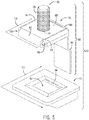
- FIG. 5 an exploded perspective view of an embodiment of the terminal post 46, the bus bar 70 having the flaps 84 folded around the base 76 of the terminal post 46, and the plastic base 72 is shown in FIG. 5 .
- the flaps 84 and the central portion 85 of the bus bar 70 form a pocket 100 which receives the base 76 of the terminal post 46.
- the pocket 100 of the bus bar 70 may block rotation of the terminal post 46 when a component (e.g., a load, or a lead to the load) is coupled with the terminal post 46.
- a component e.g., a load, or a lead to the load
- the lead e.g., to the load
- the pocket 100 e.g., formed at least by the flaps 84 and a central portion 85
- the bus bar 70 may physically contact the base 76 of the terminal post 46 to block rotation of the terminal post 46 at the base 76.
- the bus bar 70 and the terminal post 46 may together form an electrical assembly 90.
- At least a portion of the electrical assembly 90 may be overmolded by the plastic base 72 in the illustrated embodiment.
- at least the pocket 100 (e.g., formed by the flaps 84 and the central portion 85) of the bus bar 70, and the base 76 of the terminal post 46, may be overmolded by the plastic base 72.
- the electrical assembly 90 may be overmolded by the plastic base 72 such that the electrical assembly 90 (or a portion thereof) sits within an interior 92 of the plastic base 72.
- the material of the plastic base 72 may fill space between the bus bar 70 and the base 76 of the terminal post 46, thereby enhancing the ability of the terminal post 46 to resist rotation when a lead is coupled with the post 74 of the terminal post 46. Accordingly, while the interior 92 of the plastic base 72 is shown as being a generally open space for clarity in the illustrated embodiment, the interior 92 may include plastic embedded within spaces of the interior 92 that are not occupied by the electrical assembly 90 (e.g., due to overmolding).
- the plastic base 72 may include an opening 94 extending through a bottom of the plastic base 72 and in fluid communication with the interior 92 of the plastic base 72. Accordingly, an extension 96 of the bus bar 70 may be folded downwardly such that the extension 96 extends through the opening 94 in the plastic base 72.
- the extension 96 of the bus bar 70 may extend into an inside of the housing, thereby facilitating coupling of the extension 96 with an interconnected group of electrochemical ells disposed within the housing.
- extension 96 (e.g., extending through the opening 94 in the plastic base 72) may be an integral extension of the bus bar 70, or the extension 96 may be (or include) a separate component welded to, or otherwise coupled with, the bus bar 70.
- the plastic base 72 together with the electrical assembly, forms a modular terminal block assembly 110.
- the plastic base 72 may include a first cross-sectional area 111 similar in size to a second cross-sectional area 113 of the combined pocket 100 of the bus bar 70 and the base 76 of the terminal post 46.
- the first cross-sectional area 111 may be greater in size than the second cross-sectional area 113 (greater than 100% the size of the cross-sectional area 113), but less than 300% the size of the second cross-sectional area 113, less than 200% the size of the second cross-sectional area 113, less than 150% the size of the second cross-sectional area 113, less than 125% the size of the second cross-sectional area 113, less than 110% the size of the second cross-sectional area 113, less than 105% the size of the second cross-sectional area 113, or less than 1 02% the size of the second cross-sectional area 113.
- FIG. 6 A top perspective view of an embodiment of the terminal block assembly 110 of the terminal post 46, the bus bar 70 (e.g, forming the pocket 100), and the plastic base 72 is shown in FIG. 6 . Further, a bottom perspective view of an embodiment of the terminal block assembly 110 is shown in FIG. 7 . Focusing first on FIG. 7 , as previously described, the extension 96 of the bus bar 70 (or coupled with the bus bar 70) may extend through the opening 94 in the plastic base 72. The opening 94 extends through a bottom 112 of the plastic base 72, such that the extension 96 may extend from the interior 92 (e.g.. shown in FIG. 6 ) or cavity of the plastic base 72 and through the bottom 112 of the plastic base 72.
- the extension 96 may access an interior or inside of a housing (e.g., to couple with a group of interconnected electrochemical ells either directly or by coupling with intervening electrical connectors).
- the plastic base 72 may also include a recess 117 in the bottom 1.12 of the plastic base 72, which reduces an amount of material used tor the plastic base 72 and may be accessible to vent gases.
- the central portion 85 of the bus bar 70 may be exposed along an upper surface 114 of the plastic base 72.
- the central portion 85 may extend slightly above the upper surface 114.
- a lead extending from a load e.g., the load intended to be powered by the battery
- the central portion 85 of the bus bar 70 may engage (e.g., physically contact and/or press into) the central portion 85 of the bus bar 70, thereby establishing an enhanced physical connection that would not otherwise be possible if the upper surface 114 of the plastic base 72 blocked the lead from doing so.
- the lead may screw into or otherwise couple with the post 74 of the terminal post 46 until the lead contacts the central portion 85 of the bus bar 70.
- the plastic base 72 may include a slanted or tapered surface 116 configured to match (or be compatible with) a surface defining the receptacle in the housing. Accordingly, the plastic base 72 may more easily be disposed into the receptacle than would otherwise be possible if the plastic base 72 were, for example, a generally untapered prism that fits into a corresponding generally untapered receptacle. Further, the compatible tapered surface 116 and surface of the housing defining the receptacle may facilitate improved blockage of fluid ingress and egress to and from the housing.
- FIGS. 8 and 9 perspective views of the terminal block assembly 110 of FIGS. 6 and 7 being inserted into the receptacle 62 of the housing 30, and positioned within the receptacle 62 of the housing 30, respectively, are shown.
- the receptacle 62 includes, as previously described, a slanted or tapered surface 120 corresponding with the slanted or tapered surface 116 of the plastic base 72 of the terminal block assembly 110.
- the plastic base 72 may be easily received by the receptacle 62, and the tapered surfaces 116, 120 may physically contact one another, or reduce an amount of space between the housing 30 and the plastic base 72 to less than would otherwise be possible with, for example, a generally untapered base and receptacle.
- the receptacle 62 configured to receive the terminal block assembly 110 may include an opening 122 configured to receive the extension 96 of the bus bar 70. Accordingly, the extension 96 may extend through an opening in the plastic base 72 (e.g., the opening 94 in FIGS. 4 , 5 , and 7 ), and the extension 96 may extend through the opening 122 in the receptacle 62.
- the opening in the plastic base 72 e.g., the opening 94 in FIGS.
- the opening in the plastic base 72 may be offset from the opening 112 in the receptacle 62, such that a curvature 124 in the extension 96 enables the extension 96 to traverse from the plastic base 72 into the opening 122.
- the opening in the plastic base 72 e.g., the opening 94 in FIGS. 4 , 5 , and 7
- fluid ingress and egress may be reduced.
- the openings 94, 122 may be sealed to further reduce fluid ingress and egress.
- a lip 123 of the plastic base 72 is welded to one or more surfaces 125 of the housing 30 (e.g., where the surface 125 surrounds the receptacle 62) to seal the terminal block assembly 110 within the receptacle 62.
- the lip 123 may weld to two surfaces 125 separated by a channel 127, where the channel 127 acts as a labyrinth to reduce a likelihood that fluids leak into, or out of, the receptacle 62.
- the terminal block assembly 110 is shown disposed within the receptacle 62 of the housing 30.
- the plastic base 72 of the terminal block assembly 110 may be welded to the housing 30.
- the lip 123 of the plastic base 72 may be welded to the housing 30 along a weld region 130 on the upper surface 114 of the plastic base 72, In the illustrated embodiment, the lip 123 of the plastic base 72 is welded along only one weld region 130.
- the lip 123 of the plastic base 72 may be welded to more than one surface of the housing 30 along multiple weld regions.
- the plastic base 72 and/or housing 30 may be additionally or alternatively seated via other manners (e.g., by covering or welding over spaces 130 between the plastic base 72 and the housing 30).
- a strip e.g., adhesive strip
- the strip may be disposed over the central portion 85 of the bus bar 70 and the upper surface 114 of the plastic base 72, such that the strip (e.g., adhesive strip) seals the crevice between the bus bar 70 and the plastic base 72.
- the terminal post 46 includes a flange 140 instead of a post, where the flange 140 may be welded to, or retained by (e.g., via a pocket), the bus bar 70.
- a clamp of a lead may be clamped onto the flange 140, or an electrical component of the lead may be welded to the flange 140.
- the terminal post 46 includes a smooth post 142 retained by the bus bar 70 (e.g., via a pocket, as previously described), instead of having a threaded post.
- a clamp of a lead may be clamped onto the smooth post 142, instead of a threaded lead being screwed onto a threaded post.
- the terminal post 46 includes a female recess 144 instead of a post, where the female recess 144 may be a part of a base of the terminal post 46 and the base is retained by the bus bar 70.
- the female recess 144 may be integral with the bus bar 70 itself, such that no terminal post 46 is included other than the bus bar 70 itself
- the female recess 144 may be configured to receive a post of a lead.
- the female recess 144 may, in some embodiments, be threaded, such that a threaded post of the lead is screwed into the female recess.
- a technical advantage of presently disclosed embodiments is the ability to provide modular solutions having various types of terminals. For example, different terminals may be incorporated based on customer demands.
- the method 150 includes forming (block 152), via a bus bar, a pocket around a base of a terminal post.
- the bus bar may include an opening through which a post of the terminal post extends, and flaps surrounding the portion of the bus bar having the opening.
- the flaps may be folded downwardly (e.g., away from the post of the terminal post) around the base of the terminal post.
- the flaps may be betided or folded around the base by heating the flaps, or the flaps may be bended or folded around the base via a cold forming process.
- the base may be rectangular, such that the pocket, when formed around the base of the terminal post, blocks rotation of the base if a lead engages with (e.g., screws onto) the post of the terminal post.
- the bus bar and the terminal post together may form an electrical assembly, as previously described.
- the method 150 also includes overmolding (block 154) at least a portion of the electrical assembly having the bus bar and the terminal post via a plastic base.
- the pocket of the bus bar and the base of the terminal post may be overmolded by the plastic such that a central portion of the pocket of the bus bar (e.g., where the central portion includes the opening through which the post of the terminal post extends) is exposed (e.g., extends slightly above) an upper surface of the plastic base.
- the overmolded plastic may fill spaces between the bus bar and the base of the terminal post, thereby enhancing the terminal post's ability to resist rotation when the lead engages with (e.g., screws onto) the post of the terminal post.
- the method 150 also includes inserting (block 156) the terminal block assembly into a receptacle (e.g., a cavity) of a housing of the battery module.
- a receptacle e.g., a cavity
- the receptacle may be formed within the housing.
- the plastic base of the terminal block assembly may include at least one tapered surface
- the receptacle of the housing may also include a corresponding at least one tapered surface.
- the terminal block assembly may be easily inserted into the receptacle, and a mating between the plastic base of the terminal block assembly and the receptacle of the housing may be enhanced.
- a space between the tapered surface(s) of the plastic base and the tapered surface(s) of the receptacle may be less than would otherwise be possible if, for example, the plastic base and the receptacle were generally untapered.
- the method 150 also includes welding (block 158) the plastic base to the housing to seal the receptacle.
- the plastic base includes a lip that sits on one or more surfaces of the housing.
- the plastic base is welded to the one or more surfaces of the housing along a top surface of the plastic base.
- other mechanisms may be utilized to improve a seal of the terminal block assembly within the receptacle of the housing.
- an adhesive strip may be disposed over the upper surface of the plastic base and over the exposed portion of the bus bar, such that a crevice between the bus bar and the upper surface of the base is sealed,
- embodiments of the present disclosure include a terminal block assembly having a bus bar that envelops a base of a terminal post within a pocket of tire bus bar, where the pocket is defined by flaps of the bus bar that bend around the base of the terminal post.
- the pocket and the base are overmolded by a plastic base of the terminal block assembly. Overmolding the pocket and the base by the plastic base enhances an ability of the terminal post to resist rotation when a lead is engaged with the terminal post.
- forming the terminal block assembly facilitates modular manufacturing of the terminal block assembly that can be easily positioned within a receptacle of a housing, such that the electrical components of the terminal block assembly electrically couple with the electrochemical ells of the battery module.
- the plastic base of the terminal block assembly may also be welded and sealed to the plastic housing. Accordingly, the terminal posts of the battery module are easily integrated in a way that reduces fluid ingress and egress to and from the battery module.
Landscapes
- Chemical & Material Sciences (AREA)
- Chemical Kinetics & Catalysis (AREA)
- Electrochemistry (AREA)
- General Chemical & Material Sciences (AREA)
- Battery Mounting, Suspending (AREA)
- Connection Of Batteries Or Terminals (AREA)
Claims (14)
- Module (20) de batterie, comportant:- un ensemble bloc (110) de borne comprenant un ensemble électrique (90) et une embase (72) en plastique, l'ensemble électrique (90) comportant une colonne (46) de borne et une barre omnibus (70) couplée à la colonne (46) de borne, une partie de l'ensemble électrique (90) étant surmoulée par l'embase (72) en plastique, et la partie comprenant au moins une portion d'une embase (76) de colonne de borne qui s'étend vers l'extérieur à partir d'un axe central d'une partie (74) de colonne de la colonne (46) de borne ; et- un boîtier (30) en plastique doté d'un réceptacle (62) configuré pour recevoir l'embase (72) en plastique de l'ensemble bloc (110) de borne,caractérisé en ce que
l'embase (72) en plastique comporte un rebord (123) configuré pour entrer en contact avec une surface (125) du boîtier (30) en plastique entourant le réceptacle (62) du boîtier (30) en plastique, et le module (20) de batterie comportant une soudure entre le rebord (123) de l'embase (72) en plastique et la surface (125) du boîtier (30) en plastique. - Module (20) de batterie selon la revendication 1,
la barre omnibus (70) n'étant pas soudée à la colonne (46) de borne. - Module (20) de batterie selon la revendication 1 ou 2,
la barre omnibus (70) comportant une ouverture (78) et un ou plusieurs rabats (84) entourant l'ouverture (78), la partie (74) de colonne de la colonne (46) de borne s'étendant à travers l'ouverture (78) de la barre omnibus (70), et le ou les rabats (84) de la barre omnibus (70) étant repliés autour de l'embase (76) de colonne de borne ou enveloppant celle-ci pour retenir l'embase (76) de colonne de borne à l'intérieur d'une poche (100) de la barre omnibus (70). - Module (20) de batterie selon la revendication 3,
la poche (100) de la barre omnibus (70) et l'embase (76) de colonne de borne présentant une première aire combinée (113) de section droite, l'embase (72) en plastique présentant une deuxième aire (111) de section droite, et la deuxième aire (111) de section droite représentant entre 100 % et 300 % de la taille de la première aire combinée (113) de section droite. - Module (20) de batterie selon l'une des revendications 1 à 4,
l'embase (72) en plastique comportant une ouverture (94) et la barre omnibus (70) comportant un prolongement (96) configuré pour s'étendre à travers l'ouverture (94) afin d'accéder au réceptacle (62) du boîtier (30) en plastique. - Module (20) de batterie selon la revendication 5,
le réceptacle (62) du boîtier (30) en plastique comportant une ouverture supplémentaire (122) configurée pour recevoir le prolongement (96) de la barre omnibus (70) de telle façon que le prolongement (96) s'étende jusque dans un intérieur du boîtier (30) en plastique. - Module (20) de batterie selon la revendication 6,
l'ouverture supplémentaire (122) dans le réceptacle (62) étant configurée pour être alignée avec l'ouverture (94) dans l'embase (72) en plastique. - Module (20) de batterie selon la revendication 6,
l'ouverture supplémentaire (122) dans le réceptacle (62) étant configurée pour être décalée par rapport à l'ouverture (94) dans l'embase (72) en plastique, et le prolongement (96) présentant une courbure (124) pour permettre au prolongement (96) de s'étendre à travers à la fois l'ouverture supplémentaire (122) dans le réceptacle (62) et l'ouverture (94) dans l'embase (72) en plastique. - Module (20) de batterie selon l'une des revendications 1 à 8,
l'embase (72) en plastique présentant une première surface inclinée (116), le réceptacle (62) présentant une deuxième surface inclinée (120) compatible avec la première surface inclinée (116), et l'embase (72) en plastique étant disposée à l'intérieur du réceptacle (62) de telle façon que la première surface inclinée (116) soit immédiatement adjacente à la deuxième surface inclinée (120). - Module (20) de batterie selon l'une des revendications 1 à 9,
l'embase (76) de colonne de borne et la partie (74) de colonne étant intégrées entre elles. - Module (20) de batterie selon l'une des revendications 1 à 10,
la partie (74) de colonne étant une colonne filetée, une colonne lisse ou un flasque. - Module (20) de batterie selon l'une des revendications 1 à 11,
la barre omnibus (70) étant configurée pour coupler électriquement soit directement soit indirectement la colonne (46) de borne avec un groupe de cellules électrochimiques interconnectées (32) disposées dans un intérieur du boîtier (30) en plastique. - Module (20) de batterie selon l'une des revendications 1 à 12,
l'embase (76) de colonne de borne présentant une section droite rectangulaire. - Module (20) de batterie selon la revendication 13,
la barre omnibus (70) comportant des rabats (84) qui se replient autour de parties de l'embase (76) rectangulaire de colonne de borne.
Applications Claiming Priority (3)
| Application Number | Priority Date | Filing Date | Title |
|---|---|---|---|
| US201562193533P | 2015-07-16 | 2015-07-16 | |
| US15/158,321 US10177364B2 (en) | 2015-07-16 | 2016-05-18 | System and method of overmolded terminal posts of a battery module |
| PCT/US2016/041677 WO2017011366A1 (fr) | 2015-07-16 | 2016-07-10 | Système et procédé de surmoulage de bornes d'un module de batterie |
Publications (2)
| Publication Number | Publication Date |
|---|---|
| EP3323162A1 EP3323162A1 (fr) | 2018-05-23 |
| EP3323162B1 true EP3323162B1 (fr) | 2019-05-08 |
Family
ID=56684230
Family Applications (1)
| Application Number | Title | Priority Date | Filing Date |
|---|---|---|---|
| EP16751048.6A Active EP3323162B1 (fr) | 2015-07-16 | 2016-07-10 | Système et procédé de surmoulage de bornes d'un module de batterie |
Country Status (4)
| Country | Link |
|---|---|
| US (1) | US10177364B2 (fr) |
| EP (1) | EP3323162B1 (fr) |
| CN (1) | CN107810568B (fr) |
| WO (1) | WO2017011366A1 (fr) |
Families Citing this family (7)
| Publication number | Priority date | Publication date | Assignee | Title |
|---|---|---|---|---|
| CN108075060B (zh) * | 2016-11-09 | 2021-04-23 | Cps科技控股有限公司 | 具有由两种材料制成的壳体的电池包 |
| WO2018110231A1 (fr) * | 2016-12-16 | 2018-06-21 | 三洋電機株式会社 | Système de batterie ayant une structure étanche à l'eau |
| US10479422B2 (en) | 2016-12-22 | 2019-11-19 | Polaris Industries Inc. | Side-by-side vehicle |
| US10622612B2 (en) | 2018-04-19 | 2020-04-14 | Ford Global Technologies, Llc | Low voltage bus bar in high voltage battery enclosure |
| USD998560S1 (en) | 2019-02-08 | 2023-09-12 | Cps Technology Holdings Llc | Battery housing |
| USD1067123S1 (en) | 2023-01-20 | 2025-03-18 | Polaris Industries Inc. | Off-road vehicle |
| USD1120805S1 (en) | 2023-06-29 | 2026-03-31 | Polaris Industries Inc. | Body assembly for an off-road vehicle |
Family Cites Families (21)
| Publication number | Priority date | Publication date | Assignee | Title |
|---|---|---|---|---|
| US2702829A (en) | 1951-09-10 | 1955-02-22 | Miiton F Chapel | Storage battery cell plate integrator |
| US3964934A (en) | 1975-05-15 | 1976-06-22 | The Gates Rubber Company | High discharge capability sealed through connector |
| US5905002A (en) | 1997-02-13 | 1999-05-18 | Gnb Technologies, Inc. | Lead acid storage battery |
| US5861223A (en) | 1997-03-19 | 1999-01-19 | Motlagh; Mojtaba R. | Combination spring loaded battery terminal post connector and protective housing and method therefor |
| JP2002510126A (ja) | 1998-01-19 | 2002-04-02 | ジョンソン コントロールズ テクノロジー カンパニー | 迅速に搭載できるバッテリ及びホルダ |
| US7759002B2 (en) | 2001-02-15 | 2010-07-20 | Integral Technologies, Inc. | Low cost electrical terminals manufactured from conductive loaded resin-based materials |
| US7192319B1 (en) | 2005-11-28 | 2007-03-20 | Cooper Technologies Company | Insulated cable termination assembly and method of fabrication |
| US20080293277A1 (en) | 2007-05-23 | 2008-11-27 | Ajith Kuttannair Kumar | System and method for connecting a battery to a mounting system |
| DE102009000828A1 (de) | 2009-02-13 | 2010-08-19 | Robert Bosch Gmbh | Vorrichtung zur Befestigung eines Bolzens in einer Polklemme |
| WO2010095224A1 (fr) | 2009-02-18 | 2010-08-26 | トヨタ自動車株式会社 | Batterie, véhicule et appareil utilisant une batterie |
| JP5476794B2 (ja) | 2009-05-20 | 2014-04-23 | 株式会社Gsユアサ | 電池 |
| WO2011077564A1 (fr) * | 2009-12-25 | 2011-06-30 | トヨタ自動車株式会社 | Procédé pour la fabrication d'une batterie secondaire lithium ion |
| US8665056B2 (en) | 2010-05-18 | 2014-03-04 | Littlefuse, Inc. | Fuse assembly |
| WO2012067251A1 (fr) | 2010-11-17 | 2012-05-24 | Yazaki Corporation | Borne de batterie à capteur de courant |
| JP5482965B2 (ja) | 2011-05-25 | 2014-05-07 | トヨタ自動車株式会社 | 電池 |
| US9368781B2 (en) | 2011-06-27 | 2016-06-14 | Gs Yuasa International Ltd. | Terminal portion for storage batteries, plastic encapsulated terminal for storage batteries, method for producing the same, storage battery provided with terminal portion, and automobile equipped with storage battery |
| US9685677B2 (en) | 2011-10-24 | 2017-06-20 | Advanced Battery Concepts, LLC | Bipolar battery assembly |
| JP6037204B2 (ja) * | 2012-06-12 | 2016-12-07 | 株式会社Gsユアサ | 蓄電素子及び導電性部材 |
| DE102013104756B4 (de) | 2013-05-08 | 2025-07-31 | HELLA GmbH & Co. KGaA | Anordnung einer Sensorelektronik an einer Polklemme einer Batterie sowie Verfahren zur Herstellung einer derartigen Anordnung |
| JP6210736B2 (ja) | 2013-05-29 | 2017-10-11 | 矢崎総業株式会社 | ヒューズユニット |
| US20150349315A1 (en) | 2014-05-28 | 2015-12-03 | Kalas Manufacturing, Inc. | Battery post terminal connector |
-
2016
- 2016-05-18 US US15/158,321 patent/US10177364B2/en active Active
- 2016-07-10 CN CN201680038454.5A patent/CN107810568B/zh active Active
- 2016-07-10 EP EP16751048.6A patent/EP3323162B1/fr active Active
- 2016-07-10 WO PCT/US2016/041677 patent/WO2017011366A1/fr not_active Ceased
Non-Patent Citations (1)
| Title |
|---|
| None * |
Also Published As
| Publication number | Publication date |
|---|---|
| US20170018755A1 (en) | 2017-01-19 |
| CN107810568A (zh) | 2018-03-16 |
| US10177364B2 (en) | 2019-01-08 |
| EP3323162A1 (fr) | 2018-05-23 |
| CN107810568B (zh) | 2021-01-22 |
| WO2017011366A1 (fr) | 2017-01-19 |
Similar Documents
| Publication | Publication Date | Title |
|---|---|---|
| US20220320650A1 (en) | Thermal epoxy and positioning of electrochemical cells | |
| CN107278337B (zh) | 具有引导延伸部系统的蓄电池模块汇流条载体及方法 | |
| US10629884B2 (en) | Flexible ribs of a bus bar carrier | |
| EP3323162B1 (fr) | Système et procédé de surmoulage de bornes d'un module de batterie | |
| US10297812B2 (en) | Terminals of an electrochemical cell | |
| EP3243236B1 (fr) | Système de borne de module de batterie et procédé associé | |
| US20260121186A1 (en) | Battery module and bus bar having stress-relieving features | |
| US10056598B2 (en) | Recessed terminal in module body | |
| EP3201975B1 (fr) | Ensemble de connexion de barre omnibus de module de batterie | |
| EP3243234B1 (fr) | Support de barre omnibus de module de batterie ayant des extensions de guidage, système et procédé | |
| CN113381129A (zh) | 具有引导延伸部系统的蓄电池模块汇流条载体及方法 |
Legal Events
| Date | Code | Title | Description |
|---|---|---|---|
| STAA | Information on the status of an ep patent application or granted ep patent |
Free format text: STATUS: THE INTERNATIONAL PUBLICATION HAS BEEN MADE |
|
| PUAI | Public reference made under article 153(3) epc to a published international application that has entered the european phase |
Free format text: ORIGINAL CODE: 0009012 |
|
| STAA | Information on the status of an ep patent application or granted ep patent |
Free format text: STATUS: REQUEST FOR EXAMINATION WAS MADE |
|
| 17P | Request for examination filed |
Effective date: 20180116 |
|
| AK | Designated contracting states |
Kind code of ref document: A1 Designated state(s): AL AT BE BG CH CY CZ DE DK EE ES FI FR GB GR HR HU IE IS IT LI LT LU LV MC MK MT NL NO PL PT RO RS SE SI SK SM TR |
|
| AX | Request for extension of the european patent |
Extension state: BA ME |
|
| DAV | Request for validation of the european patent (deleted) | ||
| DAX | Request for extension of the european patent (deleted) | ||
| GRAP | Despatch of communication of intention to grant a patent |
Free format text: ORIGINAL CODE: EPIDOSNIGR1 |
|
| STAA | Information on the status of an ep patent application or granted ep patent |
Free format text: STATUS: GRANT OF PATENT IS INTENDED |
|
| INTG | Intention to grant announced |
Effective date: 20181123 |
|
| GRAS | Grant fee paid |
Free format text: ORIGINAL CODE: EPIDOSNIGR3 |
|
| GRAA | (expected) grant |
Free format text: ORIGINAL CODE: 0009210 |
|
| STAA | Information on the status of an ep patent application or granted ep patent |
Free format text: STATUS: THE PATENT HAS BEEN GRANTED |
|
| AK | Designated contracting states |
Kind code of ref document: B1 Designated state(s): AL AT BE BG CH CY CZ DE DK EE ES FI FR GB GR HR HU IE IS IT LI LT LU LV MC MK MT NL NO PL PT RO RS SE SI SK SM TR |
|
| REG | Reference to a national code |
Ref country code: GB Ref legal event code: FG4D |
|
| REG | Reference to a national code |
Ref country code: CH Ref legal event code: EP Ref country code: AT Ref legal event code: REF Ref document number: 1131633 Country of ref document: AT Kind code of ref document: T Effective date: 20190515 |
|
| REG | Reference to a national code |
Ref country code: DE Ref legal event code: R096 Ref document number: 602016013752 Country of ref document: DE Ref country code: IE Ref legal event code: FG4D |
|
| RAP2 | Party data changed (patent owner data changed or rights of a patent transferred) |
Owner name: CPS TECHNOLOGY HOLDINGS LLC |
|
| REG | Reference to a national code |
Ref country code: NL Ref legal event code: MP Effective date: 20190508 |
|
| REG | Reference to a national code |
Ref country code: DE Ref legal event code: R081 Ref document number: 602016013752 Country of ref document: DE Owner name: CPS TECHNOLOGY HOLDINGS LLC, NEW YORK, US Free format text: FORMER OWNER: JOHNSON CONTROLS TECHNOLOGY COMPANY, MILWAUKEE, WIS., US |
|
| REG | Reference to a national code |
Ref country code: LT Ref legal event code: MG4D |
|
| PG25 | Lapsed in a contracting state [announced via postgrant information from national office to epo] |
Ref country code: NL Free format text: LAPSE BECAUSE OF FAILURE TO SUBMIT A TRANSLATION OF THE DESCRIPTION OR TO PAY THE FEE WITHIN THE PRESCRIBED TIME-LIMIT Effective date: 20190508 Ref country code: HR Free format text: LAPSE BECAUSE OF FAILURE TO SUBMIT A TRANSLATION OF THE DESCRIPTION OR TO PAY THE FEE WITHIN THE PRESCRIBED TIME-LIMIT Effective date: 20190508 Ref country code: LT Free format text: LAPSE BECAUSE OF FAILURE TO SUBMIT A TRANSLATION OF THE DESCRIPTION OR TO PAY THE FEE WITHIN THE PRESCRIBED TIME-LIMIT Effective date: 20190508 Ref country code: SE Free format text: LAPSE BECAUSE OF FAILURE TO SUBMIT A TRANSLATION OF THE DESCRIPTION OR TO PAY THE FEE WITHIN THE PRESCRIBED TIME-LIMIT Effective date: 20190508 Ref country code: PT Free format text: LAPSE BECAUSE OF FAILURE TO SUBMIT A TRANSLATION OF THE DESCRIPTION OR TO PAY THE FEE WITHIN THE PRESCRIBED TIME-LIMIT Effective date: 20190908 Ref country code: NO Free format text: LAPSE BECAUSE OF FAILURE TO SUBMIT A TRANSLATION OF THE DESCRIPTION OR TO PAY THE FEE WITHIN THE PRESCRIBED TIME-LIMIT Effective date: 20190808 Ref country code: ES Free format text: LAPSE BECAUSE OF FAILURE TO SUBMIT A TRANSLATION OF THE DESCRIPTION OR TO PAY THE FEE WITHIN THE PRESCRIBED TIME-LIMIT Effective date: 20190508 Ref country code: AL Free format text: LAPSE BECAUSE OF FAILURE TO SUBMIT A TRANSLATION OF THE DESCRIPTION OR TO PAY THE FEE WITHIN THE PRESCRIBED TIME-LIMIT Effective date: 20190508 Ref country code: FI Free format text: LAPSE BECAUSE OF FAILURE TO SUBMIT A TRANSLATION OF THE DESCRIPTION OR TO PAY THE FEE WITHIN THE PRESCRIBED TIME-LIMIT Effective date: 20190508 |
|
| PG25 | Lapsed in a contracting state [announced via postgrant information from national office to epo] |
Ref country code: GR Free format text: LAPSE BECAUSE OF FAILURE TO SUBMIT A TRANSLATION OF THE DESCRIPTION OR TO PAY THE FEE WITHIN THE PRESCRIBED TIME-LIMIT Effective date: 20190809 Ref country code: BG Free format text: LAPSE BECAUSE OF FAILURE TO SUBMIT A TRANSLATION OF THE DESCRIPTION OR TO PAY THE FEE WITHIN THE PRESCRIBED TIME-LIMIT Effective date: 20190808 Ref country code: RS Free format text: LAPSE BECAUSE OF FAILURE TO SUBMIT A TRANSLATION OF THE DESCRIPTION OR TO PAY THE FEE WITHIN THE PRESCRIBED TIME-LIMIT Effective date: 20190508 Ref country code: LV Free format text: LAPSE BECAUSE OF FAILURE TO SUBMIT A TRANSLATION OF THE DESCRIPTION OR TO PAY THE FEE WITHIN THE PRESCRIBED TIME-LIMIT Effective date: 20190508 |
|
| REG | Reference to a national code |
Ref country code: AT Ref legal event code: MK05 Ref document number: 1131633 Country of ref document: AT Kind code of ref document: T Effective date: 20190508 |
|
| PG25 | Lapsed in a contracting state [announced via postgrant information from national office to epo] |
Ref country code: EE Free format text: LAPSE BECAUSE OF FAILURE TO SUBMIT A TRANSLATION OF THE DESCRIPTION OR TO PAY THE FEE WITHIN THE PRESCRIBED TIME-LIMIT Effective date: 20190508 Ref country code: DK Free format text: LAPSE BECAUSE OF FAILURE TO SUBMIT A TRANSLATION OF THE DESCRIPTION OR TO PAY THE FEE WITHIN THE PRESCRIBED TIME-LIMIT Effective date: 20190508 Ref country code: SK Free format text: LAPSE BECAUSE OF FAILURE TO SUBMIT A TRANSLATION OF THE DESCRIPTION OR TO PAY THE FEE WITHIN THE PRESCRIBED TIME-LIMIT Effective date: 20190508 Ref country code: CZ Free format text: LAPSE BECAUSE OF FAILURE TO SUBMIT A TRANSLATION OF THE DESCRIPTION OR TO PAY THE FEE WITHIN THE PRESCRIBED TIME-LIMIT Effective date: 20190508 Ref country code: AT Free format text: LAPSE BECAUSE OF FAILURE TO SUBMIT A TRANSLATION OF THE DESCRIPTION OR TO PAY THE FEE WITHIN THE PRESCRIBED TIME-LIMIT Effective date: 20190508 Ref country code: RO Free format text: LAPSE BECAUSE OF FAILURE TO SUBMIT A TRANSLATION OF THE DESCRIPTION OR TO PAY THE FEE WITHIN THE PRESCRIBED TIME-LIMIT Effective date: 20190508 |
|
| REG | Reference to a national code |
Ref country code: GB Ref legal event code: 732E Free format text: REGISTERED BETWEEN 20200109 AND 20200115 |
|
| REG | Reference to a national code |
Ref country code: DE Ref legal event code: R097 Ref document number: 602016013752 Country of ref document: DE |
|
| PG25 | Lapsed in a contracting state [announced via postgrant information from national office to epo] |
Ref country code: MC Free format text: LAPSE BECAUSE OF FAILURE TO SUBMIT A TRANSLATION OF THE DESCRIPTION OR TO PAY THE FEE WITHIN THE PRESCRIBED TIME-LIMIT Effective date: 20190508 Ref country code: SM Free format text: LAPSE BECAUSE OF FAILURE TO SUBMIT A TRANSLATION OF THE DESCRIPTION OR TO PAY THE FEE WITHIN THE PRESCRIBED TIME-LIMIT Effective date: 20190508 Ref country code: IT Free format text: LAPSE BECAUSE OF FAILURE TO SUBMIT A TRANSLATION OF THE DESCRIPTION OR TO PAY THE FEE WITHIN THE PRESCRIBED TIME-LIMIT Effective date: 20190508 |
|
| REG | Reference to a national code |
Ref country code: CH Ref legal event code: PL |
|
| PLBE | No opposition filed within time limit |
Free format text: ORIGINAL CODE: 0009261 |
|
| STAA | Information on the status of an ep patent application or granted ep patent |
Free format text: STATUS: NO OPPOSITION FILED WITHIN TIME LIMIT |
|
| PG25 | Lapsed in a contracting state [announced via postgrant information from national office to epo] |
Ref country code: TR Free format text: LAPSE BECAUSE OF FAILURE TO SUBMIT A TRANSLATION OF THE DESCRIPTION OR TO PAY THE FEE WITHIN THE PRESCRIBED TIME-LIMIT Effective date: 20190508 |
|
| 26N | No opposition filed |
Effective date: 20200211 |
|
| REG | Reference to a national code |
Ref country code: BE Ref legal event code: MM Effective date: 20190731 |
|
| PG25 | Lapsed in a contracting state [announced via postgrant information from national office to epo] |
Ref country code: PL Free format text: LAPSE BECAUSE OF FAILURE TO SUBMIT A TRANSLATION OF THE DESCRIPTION OR TO PAY THE FEE WITHIN THE PRESCRIBED TIME-LIMIT Effective date: 20190508 |
|
| PG25 | Lapsed in a contracting state [announced via postgrant information from national office to epo] |
Ref country code: CH Free format text: LAPSE BECAUSE OF NON-PAYMENT OF DUE FEES Effective date: 20190731 Ref country code: LI Free format text: LAPSE BECAUSE OF NON-PAYMENT OF DUE FEES Effective date: 20190731 Ref country code: SI Free format text: LAPSE BECAUSE OF FAILURE TO SUBMIT A TRANSLATION OF THE DESCRIPTION OR TO PAY THE FEE WITHIN THE PRESCRIBED TIME-LIMIT Effective date: 20190508 Ref country code: LU Free format text: LAPSE BECAUSE OF NON-PAYMENT OF DUE FEES Effective date: 20190710 Ref country code: BE Free format text: LAPSE BECAUSE OF NON-PAYMENT OF DUE FEES Effective date: 20190731 |
|
| PG25 | Lapsed in a contracting state [announced via postgrant information from national office to epo] |
Ref country code: IE Free format text: LAPSE BECAUSE OF NON-PAYMENT OF DUE FEES Effective date: 20190710 |
|
| REG | Reference to a national code |
Ref country code: DE Ref legal event code: R079 Ref document number: 602016013752 Country of ref document: DE Free format text: PREVIOUS MAIN CLASS: H01M0002300000 Ipc: H01M0050543000 |
|
| PG25 | Lapsed in a contracting state [announced via postgrant information from national office to epo] |
Ref country code: CY Free format text: LAPSE BECAUSE OF FAILURE TO SUBMIT A TRANSLATION OF THE DESCRIPTION OR TO PAY THE FEE WITHIN THE PRESCRIBED TIME-LIMIT Effective date: 20190508 |
|
| PG25 | Lapsed in a contracting state [announced via postgrant information from national office to epo] |
Ref country code: IS Free format text: LAPSE BECAUSE OF FAILURE TO SUBMIT A TRANSLATION OF THE DESCRIPTION OR TO PAY THE FEE WITHIN THE PRESCRIBED TIME-LIMIT Effective date: 20190908 |
|
| PG25 | Lapsed in a contracting state [announced via postgrant information from national office to epo] |
Ref country code: HU Free format text: LAPSE BECAUSE OF FAILURE TO SUBMIT A TRANSLATION OF THE DESCRIPTION OR TO PAY THE FEE WITHIN THE PRESCRIBED TIME-LIMIT; INVALID AB INITIO Effective date: 20160710 Ref country code: MT Free format text: LAPSE BECAUSE OF FAILURE TO SUBMIT A TRANSLATION OF THE DESCRIPTION OR TO PAY THE FEE WITHIN THE PRESCRIBED TIME-LIMIT Effective date: 20190508 |
|
| PG25 | Lapsed in a contracting state [announced via postgrant information from national office to epo] |
Ref country code: MK Free format text: LAPSE BECAUSE OF FAILURE TO SUBMIT A TRANSLATION OF THE DESCRIPTION OR TO PAY THE FEE WITHIN THE PRESCRIBED TIME-LIMIT Effective date: 20190508 |
|
| PGFP | Annual fee paid to national office [announced via postgrant information from national office to epo] |
Ref country code: DE Payment date: 20250729 Year of fee payment: 10 |
|
| PGFP | Annual fee paid to national office [announced via postgrant information from national office to epo] |
Ref country code: GB Payment date: 20250728 Year of fee payment: 10 |
|
| PGFP | Annual fee paid to national office [announced via postgrant information from national office to epo] |
Ref country code: FR Payment date: 20250725 Year of fee payment: 10 |