EP3323272B1 - Disposable cup for heating food products - Google Patents
Disposable cup for heating food products Download PDFInfo
- Publication number
- EP3323272B1 EP3323272B1 EP16722152.2A EP16722152A EP3323272B1 EP 3323272 B1 EP3323272 B1 EP 3323272B1 EP 16722152 A EP16722152 A EP 16722152A EP 3323272 B1 EP3323272 B1 EP 3323272B1
- Authority
- EP
- European Patent Office
- Prior art keywords
- heating
- cup
- printed
- heater
- usb
- Prior art date
- Legal status (The legal status is an assumption and is not a legal conclusion. Google has not performed a legal analysis and makes no representation as to the accuracy of the status listed.)
- Active
Links
Images





Classifications
-
- H—ELECTRICITY
- H05—ELECTRIC TECHNIQUES NOT OTHERWISE PROVIDED FOR
- H05B—ELECTRIC HEATING; ELECTRIC LIGHT SOURCES NOT OTHERWISE PROVIDED FOR; CIRCUIT ARRANGEMENTS FOR ELECTRIC LIGHT SOURCES, IN GENERAL
- H05B3/00—Ohmic-resistance heating
- H05B3/02—Details
- H05B3/06—Heater elements structurally combined with coupling elements or holders
-
- A—HUMAN NECESSITIES
- A47—FURNITURE; DOMESTIC ARTICLES OR APPLIANCES; COFFEE MILLS; SPICE MILLS; SUCTION CLEANERS IN GENERAL
- A47J—KITCHEN EQUIPMENT; COFFEE MILLS; SPICE MILLS; APPARATUS FOR MAKING BEVERAGES
- A47J36/00—Parts, details or accessories of cooking-vessels
- A47J36/24—Warming devices
- A47J36/2444—Drinking cups with heating means
- A47J36/2461—Drinking cups with heating means with electrical heating means
-
- A—HUMAN NECESSITIES
- A47—FURNITURE; DOMESTIC ARTICLES OR APPLIANCES; COFFEE MILLS; SPICE MILLS; SUCTION CLEANERS IN GENERAL
- A47J—KITCHEN EQUIPMENT; COFFEE MILLS; SPICE MILLS; APPARATUS FOR MAKING BEVERAGES
- A47J36/00—Parts, details or accessories of cooking-vessels
- A47J36/24—Warming devices
-
- A—HUMAN NECESSITIES
- A47—FURNITURE; DOMESTIC ARTICLES OR APPLIANCES; COFFEE MILLS; SPICE MILLS; SUCTION CLEANERS IN GENERAL
- A47J—KITCHEN EQUIPMENT; COFFEE MILLS; SPICE MILLS; APPARATUS FOR MAKING BEVERAGES
- A47J36/00—Parts, details or accessories of cooking-vessels
- A47J36/24—Warming devices
- A47J36/2411—Baby bottle warmers; Devices for warming baby food in jars
- A47J36/2433—Baby bottle warmers; Devices for warming baby food in jars with electrical heating means
-
- C—CHEMISTRY; METALLURGY
- C09—DYES; PAINTS; POLISHES; NATURAL RESINS; ADHESIVES; COMPOSITIONS NOT OTHERWISE PROVIDED FOR; APPLICATIONS OF MATERIALS NOT OTHERWISE PROVIDED FOR
- C09D—COATING COMPOSITIONS, e.g. PAINTS, VARNISHES OR LACQUERS; FILLING PASTES; CHEMICAL PAINT OR INK REMOVERS; INKS; CORRECTING FLUIDS; WOODSTAINS; PASTES OR SOLIDS FOR COLOURING OR PRINTING; USE OF MATERIALS THEREFOR
- C09D11/00—Inks
- C09D11/52—Electrically conductive inks
-
- H—ELECTRICITY
- H05—ELECTRIC TECHNIQUES NOT OTHERWISE PROVIDED FOR
- H05B—ELECTRIC HEATING; ELECTRIC LIGHT SOURCES NOT OTHERWISE PROVIDED FOR; CIRCUIT ARRANGEMENTS FOR ELECTRIC LIGHT SOURCES, IN GENERAL
- H05B3/00—Ohmic-resistance heating
- H05B3/20—Heating elements having extended surface area substantially in a two-dimensional [2D] plane, e.g. plate-heater
- H05B3/34—Heating elements having extended surface area substantially in a two-dimensional [2D] plane, e.g. plate-heater flexible, e.g. heating nets or webs
-
- H—ELECTRICITY
- H05—ELECTRIC TECHNIQUES NOT OTHERWISE PROVIDED FOR
- H05B—ELECTRIC HEATING; ELECTRIC LIGHT SOURCES NOT OTHERWISE PROVIDED FOR; CIRCUIT ARRANGEMENTS FOR ELECTRIC LIGHT SOURCES, IN GENERAL
- H05B3/00—Ohmic-resistance heating
- H05B3/40—Heating elements having the shape of rods or tubes
- H05B3/54—Heating elements having the shape of rods or tubes flexible
- H05B3/58—Heating hoses; Heating collars
-
- H—ELECTRICITY
- H05—ELECTRIC TECHNIQUES NOT OTHERWISE PROVIDED FOR
- H05B—ELECTRIC HEATING; ELECTRIC LIGHT SOURCES NOT OTHERWISE PROVIDED FOR; CIRCUIT ARRANGEMENTS FOR ELECTRIC LIGHT SOURCES, IN GENERAL
- H05B2203/00—Aspects relating to Ohmic resistive heating covered by group H05B3/00
- H05B2203/002—Heaters using a particular layout for the resistive material or resistive elements
-
- H—ELECTRICITY
- H05—ELECTRIC TECHNIQUES NOT OTHERWISE PROVIDED FOR
- H05B—ELECTRIC HEATING; ELECTRIC LIGHT SOURCES NOT OTHERWISE PROVIDED FOR; CIRCUIT ARRANGEMENTS FOR ELECTRIC LIGHT SOURCES, IN GENERAL
- H05B2203/00—Aspects relating to Ohmic resistive heating covered by group H05B3/00
- H05B2203/013—Heaters using resistive films or coatings
-
- H—ELECTRICITY
- H05—ELECTRIC TECHNIQUES NOT OTHERWISE PROVIDED FOR
- H05B—ELECTRIC HEATING; ELECTRIC LIGHT SOURCES NOT OTHERWISE PROVIDED FOR; CIRCUIT ARRANGEMENTS FOR ELECTRIC LIGHT SOURCES, IN GENERAL
- H05B2203/00—Aspects relating to Ohmic resistive heating covered by group H05B3/00
- H05B2203/016—Heaters using particular connecting means
-
- H—ELECTRICITY
- H05—ELECTRIC TECHNIQUES NOT OTHERWISE PROVIDED FOR
- H05B—ELECTRIC HEATING; ELECTRIC LIGHT SOURCES NOT OTHERWISE PROVIDED FOR; CIRCUIT ARRANGEMENTS FOR ELECTRIC LIGHT SOURCES, IN GENERAL
- H05B2203/00—Aspects relating to Ohmic resistive heating covered by group H05B3/00
- H05B2203/021—Heaters specially adapted for heating liquids
-
- H—ELECTRICITY
- H05—ELECTRIC TECHNIQUES NOT OTHERWISE PROVIDED FOR
- H05B—ELECTRIC HEATING; ELECTRIC LIGHT SOURCES NOT OTHERWISE PROVIDED FOR; CIRCUIT ARRANGEMENTS FOR ELECTRIC LIGHT SOURCES, IN GENERAL
- H05B2203/00—Aspects relating to Ohmic resistive heating covered by group H05B3/00
- H05B2203/035—Electrical circuits used in resistive heating apparatus
-
- H—ELECTRICITY
- H05—ELECTRIC TECHNIQUES NOT OTHERWISE PROVIDED FOR
- H05B—ELECTRIC HEATING; ELECTRIC LIGHT SOURCES NOT OTHERWISE PROVIDED FOR; CIRCUIT ARRANGEMENTS FOR ELECTRIC LIGHT SOURCES, IN GENERAL
- H05B3/00—Ohmic-resistance heating
- H05B3/40—Heating elements having the shape of rods or tubes
- H05B3/54—Heating elements having the shape of rods or tubes flexible
- H05B3/56—Heating cables
- H05B3/565—Heating cables flat cables
Definitions
- the present invention relates to a disposable cup intended for heating up for example a food product such as a soup, coffee beverage or instant noodle product, or for maintaining such a food product when pre-heated hot in a disposable cup over an extended period of time.
- a food product such as a soup, coffee beverage or instant noodle product
- Hot water is needed to prepare a number of food products, for example instant noodles and powdered beverages.
- Instant noodles are generally packed in plastic cups which are closed by a laminate or aluminium-based lids or foils.
- consumers need to pour hot water into the noodle cup and wait a few minutes to get the noodles ready for consumption.
- powdered beverages it is common for consumers to first boil water separately and then to pour it into a cup containing said powdered beverage. In both cases, the temperature of the hot water is dependent on the settings of the external heater used. This process relies on separate heating of water which requires the availability of an appropriate installation for heating water.
- hot food products and beverages prepared in such a way tend to slowly cool down in the cup if not consumed readily by the consumer.
- the cup holder includes a heat conductive liner engaging the bottom and lower portion of the cup and an on/off switch and a polarity switch to select heat or refrigeration.
- Those systems and thermally conductive cups are relatively expensive and are designed for being used multiple times, after being cleaned each time after use.
- CN201977418 describes a portable heating cup characterized in that a USB interface is arranged on the shell; the heating disc is connected with the USB interface, a heat filler is arranged between the heating disc and the liner and the cover body is hermetically connected with the shell. Also here, the presented solution is designed for being used multiple times, after being cleaned each time after use.
- CN202346141 describes a heat preservation container comprising a cup body, a cup cover and a handle, wherein the cup body is divided into an inner cup body and an outer-cup body, a sealed cavity is formed between the inner cup body and the outer cup body, the sealed cavity is full of heat-conducting fluid, a heating rod is fixed in the sealed cavity.
- the preservation container is designed for multiple uses.
- USB heaters can also be standalone devices which are not integrated in a cup.
- CN201986189 describes a USB heater where one end of a power line is provided with a USB interface, the other end is connected with an insulating base which is provided with a heating pipe and an indicating lamp, and connection between the base and the heating pipe is waterproof. The heating pipe is then put into a cup with cold content to heat up said content.
- the system is designed for being used many times.
- the solution should provide a direct, single one-time use cup system, which is disposable, easy to handle by the consumer and which is cheap enough that it can be economically produced as a solution for direct packaging of for example dehydrated food or beverage products, which can be reconstituted with cold water by the consumer before heating.
- the object of the present invention is to improve the state of the art and to provide a new heating cup for heating food products via USB interface and which overcomes at least some of the inconveniences described above.
- the object of the present invention pertains to a heating cup which is disposable and intended for single use only.
- the present invention provides in a first aspect a disposable heating cup for heating a food product via USB interface characterized in that the heating cup comprises a printed electrical heating circuit and a printed USB connector linked to said electrical heating circuit.
- the present invention relates to a sticker suitable for sticking onto a disposable heating cup for heating a food product, the sticker comprising at least one printed electrical heating circuit and a printed USB connector linked to the at least one electronic heating circuit.
- the invention in a third aspect, relates to a packaged food product comprising the disposable heating cup of the present invention.
- a still further aspect of the present invention is a method for heating a food or beverage product with making use of a disposable heating cup, where the heating cup comprises at least one printed electrical heating circuit and at least one printed USB connector linked to said electrical heating circuit, and where electricity for heating is provided to said printed electrical heating circuit through said printed USB connector.
- the inventors have found that very cheap and still very effective heating cups can be produced when only using a printing technology for applying an electrical heating circuit and its connecting USB connection onto regular, single use disposable paper or plastic cups.
- the inventors used an ink which comprised an electricity conducting material; no other electricity conducting materials such as cables, wires, switches, connectors, metal plates etc. were needed or used for producing those heating cups. Consequently, they can be made very cheaply and at large scale, they are disposable and ideal for applications were a single use is intended.
- the electrical heating circuit can be either printed directly onto a surface of a disposable cup, e.g. an out-side surface or an inside-surface of the cup.
- the printing is on the bottom, i.e. the base, of the cup, either inside or outside of the cup.
- the electrical heating circuit can be printed onto a sticker, which is of a paper or a laminated plastic material. This sticker, together with its USB connector, can then be attached to a disposable paper or plastic cup, either on the external base, a side wall or on an internal surface of the cup.
- the electrical heating circuit and its linked USB connector can also be printed onto such a sleeve, e.g. on the inside surface of said sleeve which is in direct contact with the side wall of the cup.
- one or several stickers comprising the printed electrical heating circuit can be attached to e.g. the inner surface of such a sleeve.
- an all printed electrical heating circuit on such a disposable paper or plastic cup is absolutely sufficient to heat a single serve amount of water (i.e. of ca. 100 - 300 ml) within a reasonable amount of time (i.e. within 5, 10 or 15 min) or at least to maintain an elevated temperature of a large liquid volume over an extended period of time with as unique source of electricity a USB port of an electronic device.
- a single serve amount of water i.e. of ca. 100 - 300 ml
- a reasonable amount of time i.e. within 5, 10 or 15 min
- evidence for this is provided in the Examples section here below.
- One of the advantages of the present invention is that it now allows producing and commercialising single-use disposable heating cups, which are for example made of paper or plastic material, which are cheap and can be produced in large quantities. Those cups can be designed and produced in such a way that they are safe for being used for food and beverage applications. Particularly, the present invention now allows to commercialize dehydrated food products such as for example soups, instant noodles, coffee beverages etc. directly provided in such single-serve, single-use cups which then can be re-hydrated by the consumer with cold water and heated via USB connection with a portable computer or other electronic device while he/she is out-of home or in an office.
- the present invention pertains in a first aspect to a disposable heating cup for heating a food product via USB interface characterized in that the heating cup comprises a printed electrical heating circuit and a printed USB connector linked to said electrical heating circuit.
- the disposable heating cup comprises at least one printed electrical heating circuit and at least one printed USB connector linked to said one electrical heating circuit.
- Disposable heating cup of the present invention means that the heating cup can be disposed of after use.
- 'disposable' is herein meant as being equivalent to 'intended for single use'. Consequently, a disposable heating cup has to correctly function at least only for the first time. It is a quick, simple, hygienic and easy-to-use solution for a consumer. It does not require cleaning or washing of the heating cup after use, as it is intended for being disposed of after its first use.
- the disposable heating cup can be sized to accommodate a variety of volumes depending on user and design requirements.
- the heating cup can for example accommodate about 100 ml, or 150 ml, and up to about 350 ml or about 500 ml in volume.
- Via USB interface means that the electric power for the printed electrical heating circuit to heat up is provided via a direct connection to a Universal Serial Bus (USB) port from an electronic device such as a computer, network adapter, a separate power charger or any other similar device.
- USB Universal Serial Bus
- Print herein refers to a process of reproducing an image using a master form or a template. Typically, printing is done with using an ink or ink-like substance. Suitable printing techniques as for the present invention are selected from the group consisting of screen printing, digital printing, inkjet printing, laser printing, off-set printing and transfer printing.
- the disposable heating cup of the present invention comprises two or more printed electrical heating circuits, all linked to one printed USB connector.
- the advantage of having two or more printed electrical heating circuits per cup is that the heating profile for a food or beverage product can be optimized, for example to heat up a product faster and more uniform.
- the number of printed electronic heating circuits in the cup also depends on the size and scope of the heating cup and also on further user and design requirements.
- the heating cup of the present invention comprises a sleeve, and wherein the electrical heating circuit is printed onto the inner side of said sleeve.
- This embodiment has several advantages as it allows for example to print the electrical heating circuit onto a flat surface i.e. the sleeve before it is wrapped around the heating cup. Furthermore, printing the heating circuit on the inner side of the sleeve brings it into close contact with the side wall of the heating cup, once wrapped around the cup, and thereby assures a best possible heat transfer from the sleeve to the cup. Still further, having it printed on the inner side of the sleeve helps that a consumer holding the cup does not easily burn his fingers.
- the heating cup of the present invention comprises a sticker and wherein the electrical heating circuit is printed onto the sticker.
- the electronic heating circuit can be printed directly onto the non-adhesive surface side of a sticker.
- the advantage of using a sticker for providing an electrical heating circuit to a disposable cup is that it is much easier to print such a circuit onto a flat surface of a sticker which is only thereafter attached to a round or un-regular surface of a heating cup.
- the solution of using a sticker allows including also the printing of the USB connector linked to said electrical heating circuit directly onto the same sticker. Thereby, for example the part of the sticker comprising the USB connector is not attached to the heating cup and allows free connection to a USB port of an electronic device.
- the sticker with the printed electronic heating circuit can be attached onto the exterior surface of a heating cup, such as a side wall of the heating cup, the base of the heating cup or to the internal side of a sleeve surrounding the heating cup.
- the sticker can be attached to the cup by any suitable adhesion technique.
- the part of the sticker which comprises the printed USB connector with the USB connector head is not firmly attached to the cup in order to enable the consumer to detach this part from the cup and to plug it into a USB port of one of his electronic devices.
- the sticker does not have to cover an entire exterior or interior surface of a heating cup.
- the extent of overlap of the sticker and the surface of the cup is designed in accordance with the amount of liquid that the cup can handle, the rate at which the liquid needs to be warmed, and the power supply specifications for heating up the heating circuit.
- the sticker may further include an adhesive layer arranged between the surface of the heating cup and e.g. the plastic laminate where the heating circuit is printed on.
- the adhesive layer may include a material selected from the group consisting of heat curing adhesive layers, UV curing adhesive layers, and pressure sensitive adhesive layers.
- the present invention relates to a disposable heating cup, wherein the electrical heating circuit is printed directly onto a surface of the heating cup.
- the surface of the heating cup can be the side wall, either inner side or external side, or the base of the heating cup.
- the printing of the electrical heating circuit is at a location which is usually not touched by a consumer, for example the base of the heating cup, either internal or external of the cup, or at a lower part of the internal side wall of the heating cup. It is expected that a direct printing of an electrical heating circuit allows the best and immediate heat transfer from the circuit to the cup and to its content.
- the electrical heating circuit and the USB connector are printed with an electricity conducting material.
- the electricity conducting material is blended with and comprises an ink, a solvent and/or a varnish.
- the electricity conducting material is selected from the group consisting of silver-based conductive ink, copper-based conductive ink, conductive polymer ink, and carbon-based resistive ink.
- the electricity conducting material can be in the form of a liquid, a powder or a wax.
- the printed electronic heating circuit may be designed in the form of a meander design, a serpentine design, a spiral design or a combination thereof.
- the printed electronic heating circuit may include any further suitable designs as long as the circuit can generate sufficient heat to warm up the cup.
- the printed electronic heating circuit may be arranged in series, in parallel, or in a combination of both series and parallel depending on user and design requirements.
- the design of the printed electronic heating circuit may include printed lines having a thickness (t) of about 10 ⁇ m to 80 ⁇ m, preferably about 20 ⁇ m to 70 ⁇ m.
- a complete printed heating circuit design may have a width of about 100 to 2000 ⁇ m, preferably of about 50 ⁇ m to 2000 ⁇ m.
- the heating circuit may also include a length (referring to the length from the start of one terminal end to the other terminal end) of about 1000 mm to 4000 mm, preferably of about 1500 mm to 2500 mm.
- the printed electronic heating circuit can have a resistance of 0.025 ⁇ /cm 2 to 0.15 ⁇ /cm 2 , and preferably of about 0.05 ⁇ /cm 2 .
- the power density applied to the printed electronic heating circuit can be between 0.1 W/cm 2 to 0.3 W/cm 2 , preferably about 0.25 W/cm 2 for example.
- the USB connector of the disposable heating cup of the present invention is printed onto a strip which is detachable from the heating cup at the one end which comprises a USB connector head.
- the electrical power is provided to the electrical heating circuit or circuits through the printed USB connector that is detachable from the heating cup at the one end which comprises a USB connector head, and the USB connector head being able to be connected to a power supply via an USB plug.
- the printed USB connector head is printed and configured to easily be mechanically engaged with and electrically connected to a standard USB plug.
- the USB plug can be a standard-A or -B plug.
- it can be a USB 2.0 (normally supplying 5V at maximum output current of 500 mA), USB 3.0 (normally supplying 5V at maximum output current of 900 mA) or a USB portable charger (normally supplying 5V at 1.0 - 2.1 A) such as e.g. an iPad charger.
- the printed USB connector can be printed for example on a PET laminate, a paper laminate or cardboard.
- this printed USB connector can then further be stuck onto or be part of a cardboard sleeve that has a pre-cut shaped part which is supporting the printed USB connector of the printed electronic heating circuit.
- the sleeve may be perforated in such a way that allows the easy detaching of the strip comprising the USB connector.
- the printed electronic heating circuit is activated in a relatively fast manner, as soon as the USB connector has been inserted at its end one end comprising the connector head into a USB power source.
- the power supply is attached to the end of the printed electronic heating circuit by detaching a part of the cardboard sleeve onto the end connection point of the heater, and plugging it into a suitable USB power source, such as a laptop for example.
- the heating cup of the present invention is preferably made of a plastic or a paper material, such as for example a plastic laminate or a paper laminate, or a combination thereof.
- the materials include PVC, polyolefin, and regular paper.
- the heating cup is made of a material which can support and maintain a liquid, hot food product for a certain period of time, the time necessary for a normal, regular consumption of such a food or beverage product. There are no complicated set-up procedures or additional warming equipment needed.
- the sticker whereon the printed electronic heating circuit is incorporated may be made of any suitable paper material or plastic laminate, including polyethylene terephthalate (PET) and polyethylene naphthalate (PEN) substrates, for example.
- PET polyethylene terephthalate
- PEN polyethylene naphthalate
- the substrate may be of a relatively rigid material so as to act as a base for subsequent deposition of materials.
- the sticker is made of PET laminate.
- the heating cup of the present invention does not comprise an electrical cable or wire.
- a "wire” as of the present invention means a slender, flexible strand or rod of metal.
- a “cable” of the present invention consists of several slender, flexible metal strands twisted together. Electrical wires and cables are typically made of copper.
- the heating cup can be produced much more cheaply by not using and integrating an electrical wire and consequently heating cups which are truly disposable can be produced at a large scale.
- the heating cups are more environmental friendly as no metal parts are present with the disposable heating cup. Furthermore, as no metal parts are present in the cups, they are also safer to be used by consumers, representing a much lower risk of injuries when handling the heating cups.
- the present invention relates to a sticker suitable for sticking onto a disposable heating cup for heating a food product, the sticker comprising at least one printed electrical heating circuit and a printed USB connector linked to the at least one electronic heating circuit.
- the sticker is made of a plastic or a paper material, or a combination thereof.
- the sticker is made of a PET laminate.
- the invention relates to a packaged food product comprising the disposable heating cup of the present invention.
- the packaged food product of the present invention is a soup, for example an instant soup, an instant noodle or other pasta product, a coffee product, a tea product, a milk drink product or a chocolate drink product.
- a still further aspect of the present invention is a method for heating a food or beverage product with making use of a disposable heating cup, where the heating cup comprises at least one printed electrical heating circuit and at least one printed USB connector linked to said electrical heating circuit, and where electricity for heating is provided to said printed electrical heating circuit through said printed USB connector.
- the disposable heating cup does not comprise any solid metal parts.
- the disposable heating cup does not comprise any electrical metal wires or cables.
- the packaged food product comprising the disposable heating cup of the present invention can be used by a consumer in the following way:
- Example 1 Design and fabrication of heating cups with various circular and base heaters
- a disposable cup as it is presently available on the Market and commercialized as a packaged food product comprising dehydrated instant noodles to be prepared by adding hot water, and intended for single-use and single-serve is shown in Figure 1 .
- the locations where different printed electrical heating circuits have been attached and tested for heating in the present examples are indicated as A for base heater, B for bottom circular sleeve and C for top circular sleeve.
- Two samples of such packaged noodle cups were measured to determine the weight of content, the amount of water required and the total weight of the content to be heated (Table 1).
- the inner base area was selected as it was the most appropriate location for flexible printed heater attachment as it is not in contact with the consumer's fingers.
- Heater resistances in the range of 2 to 10 ohms were designed and fabricated on 125 ⁇ m and 50 ⁇ m thick PET films using silver and carbon conductive inks.
- Outer large base area, dual inner and outer base, and bottom circular sleeve areas were selected as heating areas for 2 nd phase of the experiments.
- the material properties of both silver and carbon conductive inks as defined in Table 6 and Table 7 were tested as well.
- the heaters were printed directly on the PET films using screen printing technology.
- Silver conductive paste properties Description Characteristics Remarks Silver conductive paste Polymer type silver paste High conductivity and flexibility Viscosity 200-300 ps at 25°C Solid content 70-80 wt.% Curing condition 150°C for 20 minutes Sheet resistivity Below 40 m ⁇ /cm 2 At 10 ⁇ m thickness Volume resistivity 4 x 10 5 ⁇ -cm TABLE 7: Carbon conductive paste properties Description Characteristics Remarks Carbon conductive paste Silver carbon hybrid paste Excellent flexibility Viscosity 200-300 ps at 25°C Curing condition 150°C for 2 minutes Sheet resistivity 80 m ⁇ /cm 2 At 10 ⁇ m thickness
- Phase 1 Printed Inner Base Heater
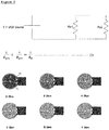
- Each base heater consists of 2 parallel resistors and its equivalent circuit is shown and described in Fig. 2 .
- the total resistance can be calculated by using the equation as indicated in the Figure.
- the layouts of various inner base heaters are shown in Figure as well. The design parameters obtained are indicated in Table 8.
- resistances between 2 to 7 ⁇ were designed to meet both USB 3 and iPad charger requirements.
- each heater consisted of 3 parallel resistors and USB power supply interconnects were also printed to enable direct plug-in to the USB source.
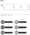
- the equivalent circuit is shown in Fig. 3 , and the total resistance can be calculated using the indicated equation.
- the layout of the outer large base heaters is presented in Fig. 3 as well.
- the design parameters as determined are shown in Table 9 and the USB trace parameters are described in Table 10.
- the dual base heater consists of 2 separate heaters: inner and outer base heaters. Each heater requires an independent USB power source which results in an increased energy density per surface area.
- the inner base heater comprises 2 parallel resistors and its equivalent circuit is shown in Fig. 2 .
- the outer base heater is formed by combining 3 resistors in parallel configuration as indicated in Fig. 4 . Detailed design parameters for both inner and outer base heaters have been determined and are presented in Tables 11 and 12, respectively.
- This printed heater is meant to be wrapped around the bottom lower area of the cup. It is a combination of 4 parallel resistors and its equivalent circuit is shown in Fig. 5 . Its total resistance can be determined by using equation indicated in the Figure. The layout of the bottom circular sleeve heater is also shown in the Figure. The design parameters were determined and are presented in Table 13. The total heater area is approximately 34 cm 2 and this heater has the largest heating surface area tested.
- Example 2 Analysis and evaluation of heating performance of the heating cups having circular and base heaters
- test set up 1 Two different test set ups were used to determine the highest temperatures that can be achieved.
- a printed inner base heater was placed at the inside bottom of an empty noodle cup.
- Thermocouples were attached to the opposite outside surface of the heater and the bottom of the cup to determine the amount of thermal energy being transferred through the base of the noodle cup.
- 250 ml of water was added to the noodle cup for the second test set up in order to measure the temperature of the water.
- Thermocouple placements were identical to the test set up 1.
- test set up 1 with a USB 2 source and with a carbon conductive inner base heater, the highest temperature of 121 °C was reached inside the cup base.
- Test configurations for 2 nd additional test are shown in Table 17. Both Plastic Cup and Paper Cup with different mass of water at various temperatures were tested to study the feasibility of warming applications. Only USB 3 source was used for the testing with the 5 ⁇ inner base heater. A water mass of 250 ml at room temperature and at 80 °C using plastic cups were tested with 5 ⁇ heater and temperatures of 33 °C and 64 °C, respectively, were maintained for at least 30 minutes. Similar tests were carried out with paper cups using 50 ml of water at room temperature and 80 °C. The water temperatures of 42 °C and 72 °C were maintained up to 20 minutes. Test results are shown in Table 18.
- USB charger which can provide maximum power of 25 watts was used to meet both USB 3 and iPad charger specifications.
- the heaters were packaged with water proof laminate and placed inside the noodle cup base. Summary of test configurations are indicated in Table 19.
- MAGGI noodle seasoning powder 300 ml of water at room temperature and calcium phosphate powder were utilized for various test set-ups as shown in the table below.
- Calcium phosphate powder which is a chemical additive was used as an activating agent to accelerate the heating process.
- Heaters were printed with silver conductive ink and two different values of heaters: 2.8 ⁇ and 2.5 ⁇ were chosen for iPad charger applications. Fabricated large base heater is the same as shown in Figure 3 .
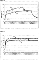
- Performance summary of various test set-ups are presented in Table 20 and the temperature profile of each test set-up are illustrated in Figure 11 . It can be seen that adding calcium phosphate powder to the seasoning powder produces a chemical reaction and accelerates the heating process above a particular activating temperature. In addition, 2 different mixing processes of calcium phosphate powder with seasoning powder were compared and were found that sprinkling method resulted in a higher final temperature. A difference in temperature of approximately 9 °C was achieved with the addition of calcium phosphate powder compared to using only seasoning powder.
- TABLE 21 Test set-up for heating cup with seasoning and calcium phosphate powder Description Plastic noodle cup contents Water content (ml) Water temperature Heater location Setup 1 Noodle + seasoning 300 Room temperature Inside the cup Setup 2 Noodle + seasoning + sprinkled 500mg Ca phosphate powder 300 Room temperature Inside the cup TABLE 22: Performance summary for USB 3 application Description T i : initial temperature inside cup base T f : final temperature inside cup base Effective Heater Area V R I P Energy Density (°C) (°C) (cm2) (V) ( ⁇ ) (mA) (watts) (watt/cm 2 ) Set up 1 28.00 57.00 18.85 5.20 5.75 999 5.19 0.28 Set up 2 26.2 56.30 18.85 5.23 5.73 1000 5.23 0.28
- inner and outer base heaters printed with silver conductive ink were chosen for evaluation. Testing conditions were similar to the previous test set-up where the heaters were packaged with water proof laminate and placed inside the noodle cup base. Inner base heater was attached to the centre of the outer base heater and both heaters had their own separate power source to increase applied energy. Temperature profiles obtained are illustrated in Figure 12 . Maximum final temperatures of 76 °C and 92 °C were obtained for both set ups, respectively.
- Inner and outer base heaters were connected in parallel configuration to achieve a much lower total resistance of 1.5 ⁇ approximately in order to increase energy density per area.
- a single voltage source was used for testing and a fabricated dual base heater in parallel configuration was connected to one single power source.
- Temperature profile of each set up is presented in Figure 12 . Maximum final temperature of 90 °C and 106 °C were obtained for both set ups, respectively.
- Example 3 Design examples of disposable heating cups of the present invention
- FIG 13 illustrates a schematic presentation of disposable heating cups of the present invention comprising each a sticker with a printed electrical heating circuit.
- Figure 13A the application of a large base heater as illustrated in Figure 3 , printed on a sticker and fixed to the outer base of a disposable cup, is shown.
- the strip with the printed USB connector and terminating with a printed USB connector head is free movable and can be connected to a USB port for providing the electricity for heating the printed heating circuit which is located at the base of the cup.
- Figure 13B shows the situation where a bottom circular sleeve heater is used as illustrated in Figure 5 .
- the printed USB connector is free movable and capable of being plugged into a USB port of e.g. a personal computer.
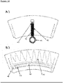
- Figure 14 is a schematic presentation of sleeves for a disposable heating cup of the present invention comprising each a printed electrical heating circuit.
- Figure 14A illustrates a sleeve solution where the design of an outer base heater, as shown in Figure 4 , is printed on the inside of the sleeve.
- the printed USB connector and connector head are further defined by a pre-cut tearing line which will allow separating the USB connector with the connector head from said sleeve and allowing free movement.
- the sleeve, after printing the electrical circuit is fixed around a disposable heating cup and the part comprising the electrical heating circuit is fixed to the outer base of the heating cup.
- a consumer in the possession of the heating cup with said sleeve will detach the USB connector strip from the sleeve and plug it into a USB port of e.g. his personal computer in order to heat up the content of the heating cup.
- Figure 14B shows an alternative solution to Figure 14A , where the electrical heating circuit is directly printed onto the inside surface of the sleeve.
- the USB connector and connector head is printed also on the inside of the sleeve and marked by a pre-cut tearing line. Upon use, a consumer can then easily detach the strip comprising the printed USB connector from the sleeve and attach it to a USB port.
Landscapes
- Engineering & Computer Science (AREA)
- Food Science & Technology (AREA)
- Chemical & Material Sciences (AREA)
- Life Sciences & Earth Sciences (AREA)
- Materials Engineering (AREA)
- Wood Science & Technology (AREA)
- Organic Chemistry (AREA)
- Cookers (AREA)
- Table Devices Or Equipment (AREA)
- General Preparation And Processing Of Foods (AREA)
- Surface Heating Bodies (AREA)
Priority Applications (1)
| Application Number | Priority Date | Filing Date | Title |
|---|---|---|---|
| PL16722152T PL3323272T3 (pl) | 2015-07-16 | 2016-05-09 | Kubek jednorazowy do podgrzewania produktów spożywczych |
Applications Claiming Priority (2)
| Application Number | Priority Date | Filing Date | Title |
|---|---|---|---|
| EP15177001 | 2015-07-16 | ||
| PCT/EP2016/060271 WO2017008932A1 (en) | 2015-07-16 | 2016-05-09 | Disposable cup for heating food products |
Publications (2)
| Publication Number | Publication Date |
|---|---|
| EP3323272A1 EP3323272A1 (en) | 2018-05-23 |
| EP3323272B1 true EP3323272B1 (en) | 2019-08-14 |
Family
ID=53717909
Family Applications (1)
| Application Number | Title | Priority Date | Filing Date |
|---|---|---|---|
| EP16722152.2A Active EP3323272B1 (en) | 2015-07-16 | 2016-05-09 | Disposable cup for heating food products |
Country Status (10)
| Country | Link |
|---|---|
| US (1) | US20180213604A1 (pl) |
| EP (1) | EP3323272B1 (pl) |
| JP (1) | JP2018527970A (pl) |
| KR (1) | KR20180030984A (pl) |
| CN (1) | CN107852779A (pl) |
| CA (1) | CA2992144A1 (pl) |
| ES (1) | ES2751574T3 (pl) |
| MY (1) | MY187083A (pl) |
| PL (1) | PL3323272T3 (pl) |
| WO (1) | WO2017008932A1 (pl) |
Families Citing this family (5)
| Publication number | Priority date | Publication date | Assignee | Title |
|---|---|---|---|---|
| JP7153659B2 (ja) * | 2017-02-23 | 2022-10-14 | ソシエテ・デ・プロデュイ・ネスレ・エス・アー | 飲料を混合して飲むための容器 |
| KR20200040375A (ko) | 2018-10-10 | 2020-04-20 | 순천대학교 산학협력단 | 리튬 이온 전지용 전해질 및 리튬 이온 전지 |
| US11274853B2 (en) | 2018-10-15 | 2022-03-15 | Goodrich Corporation | Additively manufactured heaters for water system components |
| ES2826248B2 (es) * | 2019-11-15 | 2021-10-19 | Asociacion De Investigacion De Mat Plasticos Y Conexas | Envase calefactable |
| CN111785157A (zh) * | 2020-07-17 | 2020-10-16 | 武汉世帝牧文化传媒有限公司 | 一种防伪标签 |
Family Cites Families (33)
| Publication number | Priority date | Publication date | Assignee | Title |
|---|---|---|---|---|
| US2490132A (en) * | 1945-07-26 | 1949-12-06 | William M Huston | Power shovel |
| JPS50150565A (pl) * | 1974-05-23 | 1975-12-03 | ||
| JPS5349572U (pl) * | 1976-09-30 | 1978-04-26 | ||
| JPS59115269A (ja) * | 1982-12-15 | 1984-07-03 | 株式会社 セイコウ物産東京 | 発熱体付食品容器 |
| US4933534A (en) * | 1988-11-23 | 1990-06-12 | Cunningham Paul A | Electrical heater and plug |
| CN2088830U (zh) * | 1990-07-10 | 1991-11-20 | 中山大学 | 柔性可粘贴电热膜电热炊具 |
| JPH04115166U (ja) * | 1991-03-20 | 1992-10-12 | 智仁 田川 | 差し込み金属と発熱体を付けた2000c▲m3▼以下の個体容器 |
| CN1025932C (zh) * | 1992-07-16 | 1994-09-14 | 山东大学 | 电热膜贴花纸的制作方法及应用 |
| US5436429A (en) * | 1993-07-30 | 1995-07-25 | Cline; Mitchell T. | Flexible electric heating pad for wrapping around a baby bottle powered by vehicle cigarette lighter plug |
| US6870135B2 (en) * | 2003-01-14 | 2005-03-22 | Hlc Efficiency Products Llc | Beverage container warmer |
| JP2004261493A (ja) * | 2003-03-04 | 2004-09-24 | Hitachi Metals Ltd | 飲み物容器ホルダー |
| US20040261493A1 (en) * | 2003-06-25 | 2004-12-30 | Lee Kun Ta | Adjustable cushioning device for impact tester |
| JP2005065889A (ja) * | 2003-08-22 | 2005-03-17 | Snd:Kk | 加温装置 |
| US8109668B2 (en) * | 2007-03-01 | 2012-02-07 | Hamilton Beach Brands, Inc. | Blender having an invertable jar for compact storage |
| JP3151286U (ja) * | 2009-04-02 | 2009-06-18 | 心仁 黎 | カード読み取り機能を有する温度調整コップ台 |
| US7717717B1 (en) * | 2009-06-26 | 2010-05-18 | Joseph Lai | User-friendly USB connector |
| US8555656B2 (en) | 2010-10-28 | 2013-10-15 | Qasem A. Al-Qaffas | Thermally conductive cup and holder |
| CN201977556U (zh) * | 2010-12-22 | 2011-09-21 | 深圳市智顺科技有限公司 | 车载智能电热杯 |
| CN201986189U (zh) | 2011-02-23 | 2011-09-21 | 吴江金达精工机械有限公司 | Usb加热器 |
| CN201977418U (zh) | 2011-03-18 | 2011-09-21 | 西安工业大学 | 一种便携加热杯 |
| GB2490132A (en) * | 2011-04-19 | 2012-10-24 | Tectonic Internat Ltd | Heated container |
| CN202184529U (zh) * | 2011-06-27 | 2012-04-11 | 白深谊 | 多功能可加热保温陶瓷杯 |
| US20130045632A1 (en) * | 2011-08-18 | 2013-02-21 | Joseph Lai | User-Friendly No-Metal Shell USB male Connector |
| CN202346141U (zh) | 2011-11-17 | 2012-07-25 | 朱来各 | 新型usb接口保温容器 |
| CN202375736U (zh) * | 2011-12-02 | 2012-08-15 | 王文怡 | Usb加热杯 |
| CN102551468A (zh) * | 2011-12-19 | 2012-07-11 | 晓健科技(大连)有限公司 | Usb加热水杯 |
| TW201334300A (zh) * | 2012-01-05 | 2013-08-16 | Ant Prec Industry Co Ltd | 電連接器及使用該電連接器之電子裝置 |
| JP2014142423A (ja) * | 2013-01-22 | 2014-08-07 | Denso Corp | ヘッドアップディスプレイ装置 |
| CN203106611U (zh) * | 2013-04-02 | 2013-08-07 | 王钰 | Usb加热杯 |
| CN203633908U (zh) * | 2013-12-20 | 2014-06-11 | 殷梦柯 | 加热保温杯套 |
| CN204032648U (zh) * | 2014-04-10 | 2014-12-24 | 周成程 | 一种保温杯 |
| CN203987295U (zh) * | 2014-06-18 | 2014-12-10 | 上海申航热能科技有限公司 | 一种自带电池和膜加热器保温的杯子 |
| US9565918B2 (en) * | 2014-06-19 | 2017-02-14 | Elc Management Llc | Heating system for single-use packettes |
-
2016
- 2016-05-09 ES ES16722152T patent/ES2751574T3/es active Active
- 2016-05-09 CA CA2992144A patent/CA2992144A1/en not_active Abandoned
- 2016-05-09 MY MYPI2017704844A patent/MY187083A/en unknown
- 2016-05-09 US US15/744,140 patent/US20180213604A1/en not_active Abandoned
- 2016-05-09 CN CN201680040939.8A patent/CN107852779A/zh not_active Withdrawn
- 2016-05-09 EP EP16722152.2A patent/EP3323272B1/en active Active
- 2016-05-09 WO PCT/EP2016/060271 patent/WO2017008932A1/en not_active Ceased
- 2016-05-09 KR KR1020187001009A patent/KR20180030984A/ko not_active Ceased
- 2016-05-09 PL PL16722152T patent/PL3323272T3/pl unknown
- 2016-05-09 JP JP2018501877A patent/JP2018527970A/ja active Pending
Non-Patent Citations (1)
| Title |
|---|
| None * |
Also Published As
| Publication number | Publication date |
|---|---|
| KR20180030984A (ko) | 2018-03-27 |
| ES2751574T3 (es) | 2020-04-01 |
| PL3323272T3 (pl) | 2020-03-31 |
| JP2018527970A (ja) | 2018-09-27 |
| US20180213604A1 (en) | 2018-07-26 |
| CN107852779A (zh) | 2018-03-27 |
| CA2992144A1 (en) | 2017-01-19 |
| WO2017008932A1 (en) | 2017-01-19 |
| MY187083A (en) | 2021-08-30 |
| EP3323272A1 (en) | 2018-05-23 |
Similar Documents
| Publication | Publication Date | Title |
|---|---|---|
| EP3323272B1 (en) | Disposable cup for heating food products | |
| US6847018B2 (en) | Flexible heating elements with patterned heating zones for heating of contoured objects powered by dual AC and DC voltage sources without transformer | |
| US8383995B2 (en) | Flexible hot plate and cooking unit | |
| NZ600868A (en) | An elongate heater for an electrically heated aerosol-generating system | |
| CN218483787U (zh) | 电子雾化装置及其加热组件 | |
| CN114403721A (zh) | 一种超薄加热装置 | |
| CN215838359U (zh) | 容器外壁设有检测器件的烹饪器具 | |
| CN101461282A (zh) | 电热容器及电热方法 | |
| CN215993673U (zh) | 一种智能电炒锅的厚膜发热盘 | |
| CN207070371U (zh) | 一种快热式电热容器及电加热设备 | |
| JP2009283415A (ja) | 発熱シートおよびこの発熱シートを用いた食品原料貯蔵装置 | |
| CN205410965U (zh) | 食品保温装置 | |
| CN113576267A (zh) | 一种智能电炒锅的厚膜发热盘 | |
| TWI869196B (zh) | 智能可撓性捲收保溫餐墊 | |
| CN218679423U (zh) | 双温双控加热取暖垫 | |
| JP2017075895A (ja) | 缶入飲料用温度計 | |
| CN217695501U (zh) | 保温饭盒 | |
| CN113995315A (zh) | 设有组合式检测器件的烹饪器具 | |
| CN216876072U (zh) | 一种超薄加热装置 | |
| CN204683384U (zh) | 家庭式饭菜简易加热装置 | |
| KR20120000185U (ko) | 전기충전용 보온 컵 | |
| KR101253453B1 (ko) | 발열 및 냉각 장치를 포함하는 테이블 | |
| CN207285814U (zh) | 一种底座和喂养系统 | |
| CN209489910U (zh) | 一种加热二页夹及加热袋 | |
| TWM346391U (en) | Heat-conducting toilet seat pad |
Legal Events
| Date | Code | Title | Description |
|---|---|---|---|
| STAA | Information on the status of an ep patent application or granted ep patent |
Free format text: STATUS: THE INTERNATIONAL PUBLICATION HAS BEEN MADE |
|
| PUAI | Public reference made under article 153(3) epc to a published international application that has entered the european phase |
Free format text: ORIGINAL CODE: 0009012 |
|
| STAA | Information on the status of an ep patent application or granted ep patent |
Free format text: STATUS: REQUEST FOR EXAMINATION WAS MADE |
|
| 17P | Request for examination filed |
Effective date: 20180216 |
|
| AK | Designated contracting states |
Kind code of ref document: A1 Designated state(s): AL AT BE BG CH CY CZ DE DK EE ES FI FR GB GR HR HU IE IS IT LI LT LU LV MC MK MT NL NO PL PT RO RS SE SI SK SM TR |
|
| AX | Request for extension of the european patent |
Extension state: BA ME |
|
| DAV | Request for validation of the european patent (deleted) | ||
| DAX | Request for extension of the european patent (deleted) | ||
| GRAP | Despatch of communication of intention to grant a patent |
Free format text: ORIGINAL CODE: EPIDOSNIGR1 |
|
| STAA | Information on the status of an ep patent application or granted ep patent |
Free format text: STATUS: GRANT OF PATENT IS INTENDED |
|
| INTG | Intention to grant announced |
Effective date: 20190312 |
|
| GRAS | Grant fee paid |
Free format text: ORIGINAL CODE: EPIDOSNIGR3 |
|
| RAP1 | Party data changed (applicant data changed or rights of an application transferred) |
Owner name: SOCIETE DES PRODUITS NESTLE S.A. |
|
| GRAA | (expected) grant |
Free format text: ORIGINAL CODE: 0009210 |
|
| STAA | Information on the status of an ep patent application or granted ep patent |
Free format text: STATUS: THE PATENT HAS BEEN GRANTED |
|
| AK | Designated contracting states |
Kind code of ref document: B1 Designated state(s): AL AT BE BG CH CY CZ DE DK EE ES FI FR GB GR HR HU IE IS IT LI LT LU LV MC MK MT NL NO PL PT RO RS SE SI SK SM TR |
|
| REG | Reference to a national code |
Ref country code: GB Ref legal event code: FG4D |
|
| REG | Reference to a national code |
Ref country code: CH Ref legal event code: EP Ref country code: AT Ref legal event code: REF Ref document number: 1168574 Country of ref document: AT Kind code of ref document: T Effective date: 20190815 |
|
| REG | Reference to a national code |
Ref country code: IE Ref legal event code: FG4D |
|
| REG | Reference to a national code |
Ref country code: DE Ref legal event code: R096 Ref document number: 602016018595 Country of ref document: DE |
|
| REG | Reference to a national code |
Ref country code: NL Ref legal event code: FP |
|
| REG | Reference to a national code |
Ref country code: LT Ref legal event code: MG4D |
|
| PG25 | Lapsed in a contracting state [announced via postgrant information from national office to epo] |
Ref country code: NO Free format text: LAPSE BECAUSE OF FAILURE TO SUBMIT A TRANSLATION OF THE DESCRIPTION OR TO PAY THE FEE WITHIN THE PRESCRIBED TIME-LIMIT Effective date: 20191114 Ref country code: PT Free format text: LAPSE BECAUSE OF FAILURE TO SUBMIT A TRANSLATION OF THE DESCRIPTION OR TO PAY THE FEE WITHIN THE PRESCRIBED TIME-LIMIT Effective date: 20191216 Ref country code: LT Free format text: LAPSE BECAUSE OF FAILURE TO SUBMIT A TRANSLATION OF THE DESCRIPTION OR TO PAY THE FEE WITHIN THE PRESCRIBED TIME-LIMIT Effective date: 20190814 Ref country code: BG Free format text: LAPSE BECAUSE OF FAILURE TO SUBMIT A TRANSLATION OF THE DESCRIPTION OR TO PAY THE FEE WITHIN THE PRESCRIBED TIME-LIMIT Effective date: 20191114 Ref country code: FI Free format text: LAPSE BECAUSE OF FAILURE TO SUBMIT A TRANSLATION OF THE DESCRIPTION OR TO PAY THE FEE WITHIN THE PRESCRIBED TIME-LIMIT Effective date: 20190814 Ref country code: HR Free format text: LAPSE BECAUSE OF FAILURE TO SUBMIT A TRANSLATION OF THE DESCRIPTION OR TO PAY THE FEE WITHIN THE PRESCRIBED TIME-LIMIT Effective date: 20190814 Ref country code: SE Free format text: LAPSE BECAUSE OF FAILURE TO SUBMIT A TRANSLATION OF THE DESCRIPTION OR TO PAY THE FEE WITHIN THE PRESCRIBED TIME-LIMIT Effective date: 20190814 |
|
| REG | Reference to a national code |
Ref country code: AT Ref legal event code: MK05 Ref document number: 1168574 Country of ref document: AT Kind code of ref document: T Effective date: 20190814 |
|
| PG25 | Lapsed in a contracting state [announced via postgrant information from national office to epo] |
Ref country code: AL Free format text: LAPSE BECAUSE OF FAILURE TO SUBMIT A TRANSLATION OF THE DESCRIPTION OR TO PAY THE FEE WITHIN THE PRESCRIBED TIME-LIMIT Effective date: 20190814 Ref country code: GR Free format text: LAPSE BECAUSE OF FAILURE TO SUBMIT A TRANSLATION OF THE DESCRIPTION OR TO PAY THE FEE WITHIN THE PRESCRIBED TIME-LIMIT Effective date: 20191115 Ref country code: IS Free format text: LAPSE BECAUSE OF FAILURE TO SUBMIT A TRANSLATION OF THE DESCRIPTION OR TO PAY THE FEE WITHIN THE PRESCRIBED TIME-LIMIT Effective date: 20191214 Ref country code: RS Free format text: LAPSE BECAUSE OF FAILURE TO SUBMIT A TRANSLATION OF THE DESCRIPTION OR TO PAY THE FEE WITHIN THE PRESCRIBED TIME-LIMIT Effective date: 20190814 Ref country code: LV Free format text: LAPSE BECAUSE OF FAILURE TO SUBMIT A TRANSLATION OF THE DESCRIPTION OR TO PAY THE FEE WITHIN THE PRESCRIBED TIME-LIMIT Effective date: 20190814 |
|
| PG25 | Lapsed in a contracting state [announced via postgrant information from national office to epo] |
Ref country code: TR Free format text: LAPSE BECAUSE OF FAILURE TO SUBMIT A TRANSLATION OF THE DESCRIPTION OR TO PAY THE FEE WITHIN THE PRESCRIBED TIME-LIMIT Effective date: 20190814 |
|
| REG | Reference to a national code |
Ref country code: ES Ref legal event code: FG2A Ref document number: 2751574 Country of ref document: ES Kind code of ref document: T3 Effective date: 20200401 |
|
| PG25 | Lapsed in a contracting state [announced via postgrant information from national office to epo] |
Ref country code: RO Free format text: LAPSE BECAUSE OF FAILURE TO SUBMIT A TRANSLATION OF THE DESCRIPTION OR TO PAY THE FEE WITHIN THE PRESCRIBED TIME-LIMIT Effective date: 20190814 Ref country code: AT Free format text: LAPSE BECAUSE OF FAILURE TO SUBMIT A TRANSLATION OF THE DESCRIPTION OR TO PAY THE FEE WITHIN THE PRESCRIBED TIME-LIMIT Effective date: 20190814 Ref country code: DK Free format text: LAPSE BECAUSE OF FAILURE TO SUBMIT A TRANSLATION OF THE DESCRIPTION OR TO PAY THE FEE WITHIN THE PRESCRIBED TIME-LIMIT Effective date: 20190814 Ref country code: IT Free format text: LAPSE BECAUSE OF FAILURE TO SUBMIT A TRANSLATION OF THE DESCRIPTION OR TO PAY THE FEE WITHIN THE PRESCRIBED TIME-LIMIT Effective date: 20190814 Ref country code: EE Free format text: LAPSE BECAUSE OF FAILURE TO SUBMIT A TRANSLATION OF THE DESCRIPTION OR TO PAY THE FEE WITHIN THE PRESCRIBED TIME-LIMIT Effective date: 20190814 |
|
| PG25 | Lapsed in a contracting state [announced via postgrant information from national office to epo] |
Ref country code: IS Free format text: LAPSE BECAUSE OF FAILURE TO SUBMIT A TRANSLATION OF THE DESCRIPTION OR TO PAY THE FEE WITHIN THE PRESCRIBED TIME-LIMIT Effective date: 20200224 Ref country code: SK Free format text: LAPSE BECAUSE OF FAILURE TO SUBMIT A TRANSLATION OF THE DESCRIPTION OR TO PAY THE FEE WITHIN THE PRESCRIBED TIME-LIMIT Effective date: 20190814 Ref country code: SM Free format text: LAPSE BECAUSE OF FAILURE TO SUBMIT A TRANSLATION OF THE DESCRIPTION OR TO PAY THE FEE WITHIN THE PRESCRIBED TIME-LIMIT Effective date: 20190814 |
|
| REG | Reference to a national code |
Ref country code: DE Ref legal event code: R097 Ref document number: 602016018595 Country of ref document: DE |
|
| PLBE | No opposition filed within time limit |
Free format text: ORIGINAL CODE: 0009261 |
|
| STAA | Information on the status of an ep patent application or granted ep patent |
Free format text: STATUS: NO OPPOSITION FILED WITHIN TIME LIMIT |
|
| PG2D | Information on lapse in contracting state deleted |
Ref country code: IS |
|
| 26N | No opposition filed |
Effective date: 20200603 |
|
| PG25 | Lapsed in a contracting state [announced via postgrant information from national office to epo] |
Ref country code: SI Free format text: LAPSE BECAUSE OF FAILURE TO SUBMIT A TRANSLATION OF THE DESCRIPTION OR TO PAY THE FEE WITHIN THE PRESCRIBED TIME-LIMIT Effective date: 20190814 |
|
| PG25 | Lapsed in a contracting state [announced via postgrant information from national office to epo] |
Ref country code: MC Free format text: LAPSE BECAUSE OF FAILURE TO SUBMIT A TRANSLATION OF THE DESCRIPTION OR TO PAY THE FEE WITHIN THE PRESCRIBED TIME-LIMIT Effective date: 20190814 |
|
| REG | Reference to a national code |
Ref country code: BE Ref legal event code: MM Effective date: 20200531 |
|
| PG25 | Lapsed in a contracting state [announced via postgrant information from national office to epo] |
Ref country code: LU Free format text: LAPSE BECAUSE OF NON-PAYMENT OF DUE FEES Effective date: 20200509 |
|
| PG25 | Lapsed in a contracting state [announced via postgrant information from national office to epo] |
Ref country code: IE Free format text: LAPSE BECAUSE OF NON-PAYMENT OF DUE FEES Effective date: 20200509 |
|
| PG25 | Lapsed in a contracting state [announced via postgrant information from national office to epo] |
Ref country code: BE Free format text: LAPSE BECAUSE OF NON-PAYMENT OF DUE FEES Effective date: 20200531 |
|
| PGFP | Annual fee paid to national office [announced via postgrant information from national office to epo] |
Ref country code: GB Payment date: 20220323 Year of fee payment: 7 Ref country code: CH Payment date: 20220314 Year of fee payment: 7 |
|
| PG25 | Lapsed in a contracting state [announced via postgrant information from national office to epo] |
Ref country code: MT Free format text: LAPSE BECAUSE OF FAILURE TO SUBMIT A TRANSLATION OF THE DESCRIPTION OR TO PAY THE FEE WITHIN THE PRESCRIBED TIME-LIMIT Effective date: 20190814 Ref country code: CY Free format text: LAPSE BECAUSE OF FAILURE TO SUBMIT A TRANSLATION OF THE DESCRIPTION OR TO PAY THE FEE WITHIN THE PRESCRIBED TIME-LIMIT Effective date: 20190814 |
|
| PGFP | Annual fee paid to national office [announced via postgrant information from national office to epo] |
Ref country code: PL Payment date: 20220314 Year of fee payment: 7 Ref country code: NL Payment date: 20220314 Year of fee payment: 7 Ref country code: FR Payment date: 20220308 Year of fee payment: 7 |
|
| PG25 | Lapsed in a contracting state [announced via postgrant information from national office to epo] |
Ref country code: MK Free format text: LAPSE BECAUSE OF FAILURE TO SUBMIT A TRANSLATION OF THE DESCRIPTION OR TO PAY THE FEE WITHIN THE PRESCRIBED TIME-LIMIT Effective date: 20190814 |
|
| PGFP | Annual fee paid to national office [announced via postgrant information from national office to epo] |
Ref country code: ES Payment date: 20220602 Year of fee payment: 7 Ref country code: DE Payment date: 20220316 Year of fee payment: 7 Ref country code: CZ Payment date: 20220419 Year of fee payment: 7 |
|
| REG | Reference to a national code |
Ref country code: DE Ref legal event code: R119 Ref document number: 602016018595 Country of ref document: DE |
|
| REG | Reference to a national code |
Ref country code: CH Ref legal event code: PL |
|
| REG | Reference to a national code |
Ref country code: NL Ref legal event code: MM Effective date: 20230601 |
|
| GBPC | Gb: european patent ceased through non-payment of renewal fee |
Effective date: 20230509 |
|
| PG25 | Lapsed in a contracting state [announced via postgrant information from national office to epo] |
Ref country code: LI Free format text: LAPSE BECAUSE OF NON-PAYMENT OF DUE FEES Effective date: 20230531 Ref country code: CZ Free format text: LAPSE BECAUSE OF NON-PAYMENT OF DUE FEES Effective date: 20230509 Ref country code: CH Free format text: LAPSE BECAUSE OF NON-PAYMENT OF DUE FEES Effective date: 20230531 |
|
| PG25 | Lapsed in a contracting state [announced via postgrant information from national office to epo] |
Ref country code: NL Free format text: LAPSE BECAUSE OF NON-PAYMENT OF DUE FEES Effective date: 20230601 |
|
| PG25 | Lapsed in a contracting state [announced via postgrant information from national office to epo] |
Ref country code: DE Free format text: LAPSE BECAUSE OF NON-PAYMENT OF DUE FEES Effective date: 20231201 Ref country code: GB Free format text: LAPSE BECAUSE OF NON-PAYMENT OF DUE FEES Effective date: 20230509 |
|
| PG25 | Lapsed in a contracting state [announced via postgrant information from national office to epo] |
Ref country code: FR Free format text: LAPSE BECAUSE OF NON-PAYMENT OF DUE FEES Effective date: 20230531 |
|
| REG | Reference to a national code |
Ref country code: ES Ref legal event code: FD2A Effective date: 20240628 |
|
| PG25 | Lapsed in a contracting state [announced via postgrant information from national office to epo] |
Ref country code: ES Free format text: LAPSE BECAUSE OF NON-PAYMENT OF DUE FEES Effective date: 20230510 |
|
| PG25 | Lapsed in a contracting state [announced via postgrant information from national office to epo] |
Ref country code: ES Free format text: LAPSE BECAUSE OF NON-PAYMENT OF DUE FEES Effective date: 20230510 |
|
| PG25 | Lapsed in a contracting state [announced via postgrant information from national office to epo] |
Ref country code: PL Free format text: LAPSE BECAUSE OF NON-PAYMENT OF DUE FEES Effective date: 20230509 |
|
| PG25 | Lapsed in a contracting state [announced via postgrant information from national office to epo] |
Ref country code: PL Free format text: LAPSE BECAUSE OF NON-PAYMENT OF DUE FEES Effective date: 20230509 |