EP3323432A2 - Appareil de stérilisation et de depyrogenisation - Google Patents
Appareil de stérilisation et de depyrogenisation Download PDFInfo
- Publication number
- EP3323432A2 EP3323432A2 EP17201929.1A EP17201929A EP3323432A2 EP 3323432 A2 EP3323432 A2 EP 3323432A2 EP 17201929 A EP17201929 A EP 17201929A EP 3323432 A2 EP3323432 A2 EP 3323432A2
- Authority
- EP
- European Patent Office
- Prior art keywords
- advancement
- objects
- machine
- thermal
- conveyor belt
- Prior art date
- Legal status (The legal status is an assumption and is not a legal conclusion. Google has not performed a legal analysis and makes no representation as to the accuracy of the status listed.)
- Withdrawn
Links
Images


Classifications
-
- A—HUMAN NECESSITIES
- A61—MEDICAL OR VETERINARY SCIENCE; HYGIENE
- A61L—METHODS OR APPARATUS FOR STERILISING MATERIALS OR OBJECTS IN GENERAL; DISINFECTION, STERILISATION OR DEODORISATION OF AIR; CHEMICAL ASPECTS OF BANDAGES, DRESSINGS, ABSORBENT PADS OR SURGICAL ARTICLES; MATERIALS FOR BANDAGES, DRESSINGS, ABSORBENT PADS OR SURGICAL ARTICLES
- A61L2/00—Disinfection or sterilisation of materials or objects, in general; Accessories therefor
- A61L2/02—Disinfection or sterilisation of materials or objects, in general; Accessories therefor using physical processes
- A61L2/04—Heat
- A61L2/06—Hot gas
-
- B—PERFORMING OPERATIONS; TRANSPORTING
- B65—CONVEYING; PACKING; STORING; HANDLING THIN OR FILAMENTARY MATERIAL
- B65B—MACHINES, APPARATUS OR DEVICES FOR, OR METHODS OF, PACKAGING ARTICLES OR MATERIALS; UNPACKING
- B65B55/00—Preserving, protecting or purifying packages or package contents in association with packaging
- B65B55/02—Sterilising, e.g. of complete packages
- B65B55/04—Sterilising wrappers or receptacles prior to, or during, packaging
- B65B55/06—Sterilising wrappers or receptacles prior to, or during, packaging by heat
-
- A—HUMAN NECESSITIES
- A61—MEDICAL OR VETERINARY SCIENCE; HYGIENE
- A61L—METHODS OR APPARATUS FOR STERILISING MATERIALS OR OBJECTS IN GENERAL; DISINFECTION, STERILISATION OR DEODORISATION OF AIR; CHEMICAL ASPECTS OF BANDAGES, DRESSINGS, ABSORBENT PADS OR SURGICAL ARTICLES; MATERIALS FOR BANDAGES, DRESSINGS, ABSORBENT PADS OR SURGICAL ARTICLES
- A61L2103/00—Materials or objects being the target of disinfection or sterilisation
- A61L2103/23—Containers other than laboratory or medical, e.g. bottles or mail
Definitions
- the present invention relates to a sterilization and depyrogenation machine for containers for chemical-pharmaceutical use, particularly of the energy-saving type.
- thermal treatment that essentially consists in raising the temperature of these containers to a maximum of 350°C with dry heat and with subsequent cooling to ambient temperature or higher at no more than 10°C.
- this tunnel-like machine is inserted downstream of a washing machine for containers, which operates in a sterile environment, and upstream of machines for the dosage and closure of said containers, which operate in a contaminated environment.
- Sterilization and depyrogenation machines of the known type are formed by three contiguous thermal chambers crossed by a conveyor belt made of stainless steel, the function of which is to transfer the containers that arrive from the washing machine through the first chamber, termed entry chamber, through the second chamber, termed depyrogenation chamber, and through the third chamber, termed cooling chamber.
- the entry chamber has the function of isolating, with an overpressure of sterile filtered air, the containers that arrive from the washing machine from environmental particle contaminations and can be preheated by using the air expelled to cool the treated objects.
- Dust which as is known is the greatest vehicle of spores, bacteria and other contaminating particles, can in fact become attached to the containers that arrive from the washing machine, since they are still wet.
- the depyrogenation and cooling chambers instead have the function respectively of raising the temperature of the containers to a maximum of 350°C and then of cooling them to complete the sterilization cycle and allow the execution of the steps for filling and closing said containers.
- the conveyor belt passes through the three thermal chambers in both directions, consequently increasing the energy dispersion caused by a double heating/cooling for each complete turn.
- sterilization and depyrogenation machines of the known type are not free from drawbacks, which include the fact that they have a high energy consumption caused at least for 40%/50% by the fact that part of the energy required for the thermal treatment of the containers is wasted in order to vary continuously the temperature of the conveyor belt, which at each cycle undergoes an unnecessary heating and cooling.
- said portion in fact carries containers which must be heated but has a lower temperature than said containers and therefore, requiring a longer travel time, especially in the second chamber, in order to ensure that the entire container is heated according to the technical specifications of the sterilization and depyrogenation process, comprising the resting base thereof, which, being in contact with the conveyor belt, is the last part of the container to reach the desired temperature.
- the aim of the present invention is to provide a sterilization and depyrogenation machine for containers for chemical-pharmaceutical use that obviates the drawbacks noted above and is such as to overcome the limitations of the background art.
- an object of the present invention is to provide a sterilization and depyrogenation machine for containers for chemical-pharmaceutical use that is capable of eliminating, in the operating condition, the energy consumption for heating and cooling caused by the system for the conveyance of the containers to be treated, allowing an energy saving comprised between 40% and 50% of the power required for the process for sterilization and depyrogenation of the treated containers.
- Another object of the present invention is to provide a sterilization and depyrogenation machine for containers for chemical-pharmaceutical use that prevents the conveyance of unwanted contaminations through the system for the conveyance of the containers to be treated.
- a further object of the present invention is to provide a sterilization and depyrogenation machine for containers for chemical-pharmaceutical use that offers the greatest assurances of reliability and operation.
- a still further object of the present invention is to provide a sterilization and depyrogenation machine for containers for chemical-pharmaceutical use that uses production and operation technologies that are easily commercially available and is therefore easy and quick to provide and therefore economically competitive if compared with similar objects of the known type.
- a sterilization and depyrogenation machine for containers for chemical-pharmaceutical use comprising a plurality of thermal chambers adapted to perform a process for the sterilization and depyrogenation of objects for chemical-pharmaceutical use and arranged mutually in sequence along an advancement line of said objects in a thermally independent manner, said thermal chambers being provided with openings for the entry and exit of said objects which are formed transversely along and with respect to said advancement line in such a manner as to give said machine a tunnel-like configuration, characterized in that it comprises means for the advancement of said objects which are adapted to transfer said objects through said thermal chambers and are arranged mutually in sequence along said advancement line so as to define a plurality of advancement sectors, which are equal in number to at least one for each one of said thermal chambers, so that each one of said advancement means that belongs to the same one of said advancement sectors undergoes the thermal influence of only one of said thermal chambers
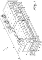
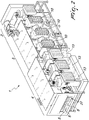
- the sterilization and depyrogenation machine for containers for chemical-pharmaceutical use comprises a plurality of thermal chambers 2, 3 and 4 adapted for the execution of a process for the sterilization and depyrogenation of objects 5 for chemical-pharmaceutical use, such as for example containers of the type of ampoules and/or bottles made of glass, aluminum or stainless steel, adapted to contain sterile and non-pyrogenic drugs, and arranged in sequence with respect to each other along a line 6 for the advancement of the objects 5 in a thermally independent manner.
- said thermal chambers 2, 3 and 4 are provided with entry and exit openings for the objects 5 which are formed transversely along and with respect to the advancement line 6 in such a manner as to give the machine 1 a tunnel-like configuration.
- the machine 1 described herein is configured substantially according to the traditional layout of sterilization and depyrogenation machines for containers for chemical-pharmaceutical use.
- the machine 1 in fact comprises a first thermal chamber 2, termed entry chamber, which has the task of insulating, with a laminar flow 7 of sterile filtered air with absolute filters 7a in overpressure, the objects 5 that arrive from washing machines against environmental particle contamination and can be preheated by using the air expelled to cool the treated objects 5.
- entry chamber which has the task of insulating, with a laminar flow 7 of sterile filtered air with absolute filters 7a in overpressure, the objects 5 that arrive from washing machines against environmental particle contamination and can be preheated by using the air expelled to cool the treated objects 5.
- depyrogenation chamber which has the function of heating the objects 5 up to their complete sterilization by means of a laminar flow 8 of air filtered with absolute filters 9 and heated with electric resistance heaters 10, which by striking vertically from above downward the objects 5 progressively transfers heat to them.
- cooling chamber which has the task of cooling the sterilized objects 5 that exit from the second chamber 3 by means of a laminar flow 11 of air filtered with absolute filters 12 which can be cooled with refrigeration units, with electric refrigeration systems or with air/water exchangers 13 or with the intake of treated environmental air.
- the objects 5 are ready and suitable for the subsequent steps for filling and closing them.
- means 14 for the advancement of the objects 5 which are adapted for the transfer of the latter through the thermal chambers 2, 3 and 4 and are arranged in sequence with respect to each other along the advancement line 6 in such a manner as to define a plurality of advancement sectors 15, 16 and 17 which are equal in number to at least one for each thermal chamber 2, 3 and 4, so that each advancement means 14 that is part of the same advancement sector 15, 16 or 17 undergoes the thermal influence of a single thermal chamber 2, 3 or 4.
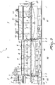
- said advancement means 14 comprise a plurality of conveyor belts 18, 19 and 20, one for each advancement sector 15, 16 and 17, which have the function of transferring sequentially the objects 5 that arrive for example from the washing machine through the thermal chambers 2, 3 and 4.
- the conveyor belts 18, 19 and 20 have a continuous motion and are fully accommodated inside the respective thermal chamber 2, 3 or 4 in such a manner as to keep its temperature substantially constant with the machine 1 in the operating condition.
- connection means 21 formed between each pair of conveyor belts 18, 19 and 20 and adapted to allow the sliding passage of the objects 5 from each conveyor belt 18, 19 and 20 to the next one.
- said coplanar connection means 21 comprise at least two planar elements 22 and 23 which are interposed in sequence with respect to each other between the conveyor belts 18, 19 and 20 and are comb-shaped, so as to be mutually associated so that the teeth of one are accommodated with play in the recesses of the other.
- each planar element 22 and 23 is partially superimposed on the adjacent conveyor belt 18, 19 or 20 at the end part of the latter with an edge 24 that is rounded on the opposite side with respect to the one designed to support the objects 5 in such a manner as to support them as soon as the conveyor belt 18, 19 or 20 winds around its respective supporting roller.
- planar elements 22 and 23 are slidingly mutually associated along the advancement line 6 so as to compensate the thermal expansion of the material of which they are made, which can be, for example, stainless steel.
- the first one of each pair of said planar elements 22 and 23, established along the direction of advancement of the advancement line 6, defines a sliding plane that is parallel and is arranged at a level that is higher than or equal to that of the sliding surface defined by the second of said planar elements 22 and 23, always established along the advancement direction of the advancement line 6.
- each pair of said thermal chambers 2, 3 and 4 there are means 25 for compensating the thermal expansion of the hottest of said two thermal chambers 2, 3 or 4 toward the coldest of said two thermal chambers 2, 3 or 4 in such a manner as to compensate the thermal expansion of the material of which they are made, ensuring at the same time the insulation of the advancement line 6 from the outside environment both for the portions formed inside the thermal chambers 2, 3 and 4 and for the transition portions formed between one thermal chamber 2, 3 or 4 and the other.
- said compensation means 25 comprise accordion structures 26 formed between the openings of two consecutive thermal chambers 2, 3 or 4.
- said unloading plane 27 which can be of the type with suction in partial vacuum, is partially superimposed on said last conveyor belt 20 at the end part of the latter, with an edge that is rounded on the opposite side with respect to the one designed to support the objects 5 so as to support them as soon as the conveyor belt 20 winds around its respective supporting roller.
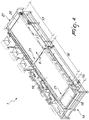
- means 28 are provided for the additional advancement of the objects 5 arranged on the advancement line 6 for at least one unmoved portion of said advancement line 6 that is defined at at least one pair of planar elements 22 and 23 and/or at said unloading plane 27.
- these additional advancement means 28 are provided exclusively only at the unloading plane 27, without however excluding that they might be installed in other portions of the advancement line 6.
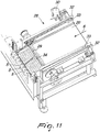
- said additional advancement means 28 comprise an advancement bar 29, which is arranged in an upward region and transversely at least with respect to the end portion of the conveyor belt 20 so as to not interfere with the objects 5 that move thereon and is movable horizontally by virtue of motor means 30 in a manner which is parallel to the advancement direction of the objects 5 between an initial position, located at an intermediate portion of the conveyor belt 20, and a final position, located proximate to the end of said conveyor belt 20.
- Said additional advancement means 28 comprise furthermore an expulsion bar 31 which is integral in horizontal translation with the advancement bar 29 and is articulated thereto for its movement between an inactive position, in which said expulsion bar 31 is arranged upward and transversely to said end portion of the conveyor belt 20 in such a manner as to not interfere with the objects 5 that move thereon, and an active position, in which said expulsion bar 31 is arranged at a distance from the conveyor belt 20 such as to engage and push the objects 5 at their resting base to the end of the unmoved portion of the advancement line 6, i.e., to the end of the unloading plane 27.
- the expulsion bar 31 can move from the inactive position to the active position by means of a cam profile that is associated therewith and is formed on the side walls 32 of the thermal chamber 4 in which it operates and comprises a pair of pins 33 which are associated oppositely with respect to each other with said side walls 32 and are adapted to support the arms 34, by means of which the expulsion bar 31 is articulated to the advancement bar 29, for a first advancement portion of the latter from the initial position to the final position.
- the expulsion bar 31 is moved from the inactive position to the active position by gravity once the advancement bar 29 has moved beyond said pins 33 during its movement from the initial position to the final position.
- the expulsion bar 31 is moved from the active position to the inactive position following the engagement of said arms 34 on the part of the pins 33 during the movement of the advancement bar 29 from the final position to the initial position.
- sterilization and depyrogenation machine 1 for containers for chemical-pharmaceutical use particularly of the energy-saving type, according to the present invention is clear and intuitive from what has been described so far.
- the objects 5 for chemical-pharmaceutical use which as already mentioned can consist of containers such as ampoules and/or bottles made of glass, aluminum or stainless steel, which exit from a washing machine, are placed on the first conveyor belt 18 along the advancement line 6 at the inlet of the first thermal chamber 2.
- these objects 5 are arranged in parallel rows which are oriented transversely with respect to said advancement line 6 in such a manner that the objects 5 of each row are in contact with the objects 5 of the next row.
- the first conveyor belt 18 advances and the first thermal chamber 2 performs its thermal treatment, with which, by means of the laminar flow 7 of sterile filtered air in overpressure and preheated with the use of the air expelled to cool the treated objects 5, insulates the objects 5 that arrive from the washing machine against environmental particle contamination.
- each row of objects 5 is pushed by the next row in such a manner as to slide on the coplanar connection means 21 formed by the two planar elements 22 and 23 interposed in mutual sequence between the conveyor belts 18 and 19.
- the objects 5 that exit from the first thermal chamber 2 are unloaded onto the second conveyor belt 19 at the inlet of the second thermal chamber 3, maintaining their orientation in parallel rows which are oriented transversely with respect to said advancement line 6 in such a manner that the objects 5 of each row are in contact with the objects 5 of the subsequent row.
- the belt advances and the second thermal chamber 3 performs its thermal treatment, by means of which, with a laminar flow 8 of air that is filtered and heated with electric resistance heaters 10, striking the objects 5 vertically downward from above, it progressively transfers heat to said objects 5, in order to heat them until they are fully sterilized.
- the objects 5 undergo heating from the bottom upward, by radiation and conduction, by virtue of the transfer of heat from the second conveyor belt 19 to said objects 5 which are colder and lie above it, adding to the heating by convection due to the laminar flow 8, which operates downward from above, thus allowing the second thermal chamber 3 to operate at a lower operating temperature than sterilization and depyrogenation machines of the known type.
- each row of objects 5 is pushed by the next row in such a manner as to slide on the coplanar connection means 21 formed by the two planar elements 22 and 23 which are interposed in mutual sequence between the conveyor belts 19 and 20.
- the objects 5 that exit from the second thermal chamber 3 are unloaded onto the third conveyor belt 20 at the inlet of the third thermal chamber 4, maintaining their orientation in parallel rows which are oriented transversely with respect to said advancement line 6 so that the objects 5 of each row are in contact with the objects 5 of the next row.
- the third thermal chamber 4 performs its thermal treatment, by means of which, with a laminar flow 11 of filtered and cold air which strikes vertically downward from above, the objects 5 are cooled in such a manner that they are ready and suitable for the subsequent filling and closing steps.
- each row of objects 5 is pushed by the next row in such a manner as to slide on the unloading plane 27 arranged at the end of the last conveyor belt 20 along the advancement direction of the advancement line 6.
- the additional advancement means 28 intervene in order to allow the complete advancement of the objects 5 on the unloading plane 27.
- the motor means 30 actuate the advancement bar 29 from its initial position to its final position, consequently moving by gravity in a controlled manner, by virtue of the work performed by the pins 33 with the arms 34, the expulsion bar 31 from its inactive position to its active position, so as to push the objects 5 and clear completely the advancement line 6.
- each conveyor belt does not absorb energy, neither to warm up nor to cool down, since it operates at a substantially constant operating temperature which is equal to the operating temperature of the respective thermal chamber with which it is associated.
- Another advantage of the machine according to the present invention resides in that as regards the second thermal chamber, termed depyrogenation chamber, the heat exchange for raising the objects to be treated to their intended temperature occurs with a flow of hot air downward from above, which adds to the radiation and conduction effect that the second conveyor belt entails on the objects carried by it.
- the energy for performing the cooling of the objects also is lower than that required with machines of the known type, since the conveyor belt of the third chamber is at a lower temperature, which is equal to the temperature of said chamber and requires no further cooling.
- a further advantage of the machine according to the present invention resides in that if there are hazardous packagings (antibiotic powders, cytotoxic substances, etc.) downstream of the machine which with the single conveyor belt might be transferred to the entry area of the machine, with consequent environmental contamination, this does not occur in the case of split belts.
- a last advantage of the machine according to the present invention resides in that the containers are heated to lower temperatures with respect to machines of the known type, with a consequent greater machinability in the subsequent operations for filling, closing, etc.
- the materials used, as well as the contingent shapes and dimensions may be any according to the requirements and the state of the art.
Landscapes
- Health & Medical Sciences (AREA)
- Engineering & Computer Science (AREA)
- Mechanical Engineering (AREA)
- Epidemiology (AREA)
- Life Sciences & Earth Sciences (AREA)
- Animal Behavior & Ethology (AREA)
- General Health & Medical Sciences (AREA)
- Public Health (AREA)
- Veterinary Medicine (AREA)
- Apparatus For Disinfection Or Sterilisation (AREA)
- Medical Preparation Storing Or Oral Administration Devices (AREA)
Applications Claiming Priority (1)
| Application Number | Priority Date | Filing Date | Title |
|---|---|---|---|
| IT102016000115684A IT201600115684A1 (it) | 2016-11-16 | 2016-11-16 | Macchina di sterilizzazione e di depirogenazione per contenitori ad uso chimico-farmaceutico, particolarmente del tipo a risparmio energetico. |
Publications (2)
| Publication Number | Publication Date |
|---|---|
| EP3323432A2 true EP3323432A2 (fr) | 2018-05-23 |
| EP3323432A3 EP3323432A3 (fr) | 2018-10-17 |
Family
ID=58670137
Family Applications (1)
| Application Number | Title | Priority Date | Filing Date |
|---|---|---|---|
| EP17201929.1A Withdrawn EP3323432A3 (fr) | 2016-11-16 | 2017-11-15 | Appararail de stérilisation et de depyrogenisation |
Country Status (2)
| Country | Link |
|---|---|
| EP (1) | EP3323432A3 (fr) |
| IT (1) | IT201600115684A1 (fr) |
Cited By (1)
| Publication number | Priority date | Publication date | Assignee | Title |
|---|---|---|---|---|
| IT202300004290A1 (it) * | 2023-03-08 | 2024-09-08 | Gerardo FUMAGALLI | Apparato di depirogenazione e/o sterilizzazione per flaconi e/o contenitori |
Family Cites Families (13)
| Publication number | Priority date | Publication date | Assignee | Title |
|---|---|---|---|---|
| US3678244A (en) * | 1971-06-18 | 1972-07-18 | Paul W Worline | Film shrinking tunnel utilizing hot air and water as heat transfer medium |
| CA1124511A (fr) * | 1979-05-16 | 1982-06-01 | Donald J. Schwalm | Four a recuire le cuivre sous atmosphere controlee |
| US5129212A (en) * | 1990-11-08 | 1992-07-14 | Liqui-Box/B-Bar-B Corporation | Method and apparatus for automatically filling and sterilizing containers |
| DE4217054A1 (de) * | 1992-05-22 | 1993-11-25 | Bausch & Stroebel Maschf | Sterilisiertunnel |
| US5787682A (en) * | 1997-06-03 | 1998-08-04 | Ossid Corporation | Method and apparatus for shrinking end seams in a film wrapped around a product |
| DE19804386C2 (de) * | 1998-02-04 | 1999-12-30 | Ttp Ingenieurbuero | Verfahren und Vorrichtung zur Trocknung oder Wärmebehandlung von Produkten, insbesondere mit Hilfe von Mikrowellenstrahlung, und damit hergestellte Bananenchips und Bananenpulver |
| DE19920057A1 (de) * | 1999-05-03 | 2000-11-09 | Kallfass Gmbh | Verfahren und Vorrichtung zur Verpackung von Gegenständen in Schrumpffolie |
| IT1314894B1 (it) * | 2000-12-22 | 2003-01-16 | Aautomag S R L | Complesso per la sterilizzazione in continuo di flaconi od altricontenitori per uso farmaceutico o simile |
| ITMI20011825A1 (it) * | 2001-08-29 | 2003-03-01 | Smi Spa | Forno a tunnel di termoretrazione per la produzione di imballaggi in pellicole di materiale termoretraibile e procedimento di imballaggio re |
| ITBO20060223A1 (it) * | 2006-03-31 | 2007-10-01 | Neri S P A | Metodo per la sterilizzazione e/o depirogenazione di contenitori ed impianto che attua detto metodo. |
| NL2006752C2 (en) * | 2011-05-10 | 2012-11-13 | Fuji Seal Europe Bv | Apparatus and method for heat shrinking a film wrapping an object. |
| CN202666037U (zh) * | 2012-07-17 | 2013-01-16 | 上海东富龙科技股份有限公司 | 一种用于隧道式灭菌烘箱内外箱体的连接结构 |
| ITUB20153071A1 (it) * | 2015-08-11 | 2017-02-11 | Sovema Spa | Impianto per la realizzazione di piastre per accumulatori elettrici e relativo procedimento di realizzazione di dette piastre |
-
2016
- 2016-11-16 IT IT102016000115684A patent/IT201600115684A1/it unknown
-
2017
- 2017-11-15 EP EP17201929.1A patent/EP3323432A3/fr not_active Withdrawn
Non-Patent Citations (1)
| Title |
|---|
| None |
Cited By (1)
| Publication number | Priority date | Publication date | Assignee | Title |
|---|---|---|---|---|
| IT202300004290A1 (it) * | 2023-03-08 | 2024-09-08 | Gerardo FUMAGALLI | Apparato di depirogenazione e/o sterilizzazione per flaconi e/o contenitori |
Also Published As
| Publication number | Publication date |
|---|---|
| IT201600115684A1 (it) | 2018-05-16 |
| EP3323432A3 (fr) | 2018-10-17 |
Similar Documents
| Publication | Publication Date | Title |
|---|---|---|
| US10683229B2 (en) | Glass sheet support structure | |
| US7842230B2 (en) | Continuous carburizing furnace | |
| KR101627503B1 (ko) | 고온 진공 열처리로의 이송장치 | |
| JP5681253B1 (ja) | 管材の熱処理装置 | |
| BR112018008794B1 (pt) | Sistema de processamento para processar folha de vidro quente | |
| EP3323432A2 (fr) | Appareil de stérilisation et de depyrogenisation | |
| SE531990C2 (sv) | Förfarande för värmebehandling av långa stålprodukter | |
| US12171891B2 (en) | Sterilisation tunnel of pharmaceutical containers | |
| CN106435602B (zh) | 一种推盘压淬装置 | |
| KR102762588B1 (ko) | 유리 시트 ??칭 기구 | |
| US10260814B2 (en) | Conveyance device for heat treatment device and heat treatment device | |
| EP1512929A2 (fr) | Four en particulier pour le traitement d'articles en verre, et procédé de chauffage d'articles en verre | |
| RU2605857C2 (ru) | Печь для обжига стеклянных блоков | |
| JP2014214969A (ja) | 連続熱処理炉 | |
| JP4300815B2 (ja) | 熱処理装置 | |
| EP1569874A1 (fr) | Machine et procede de faconnage, de recuisson et de refroidissement de feuilles de verre ou de materiaux similaires | |
| JP6152295B2 (ja) | 溶接方法及び設備 | |
| JP4354600B2 (ja) | 加熱基板搬送機構及び搬送方法 | |
| CN110719896A (zh) | 用于输送盘片的辊式运送器 | |
| KR100718746B1 (ko) | Fpd용 급속 건조 장치 | |
| CN204080033U (zh) | 车轮连续加热炉 | |
| JPH0673692U (ja) | 真空熱処理炉 | |
| CN115654845A (zh) | 一种真空干燥机及其工作方法 | |
| JPH01155185A (ja) | 連続式焼結炉 | |
| JP2001245775A (ja) | 飲食物用循環搬送路 |
Legal Events
| Date | Code | Title | Description |
|---|---|---|---|
| PUAI | Public reference made under article 153(3) epc to a published international application that has entered the european phase |
Free format text: ORIGINAL CODE: 0009012 |
|
| AK | Designated contracting states |
Kind code of ref document: A2 Designated state(s): AL AT BE BG CH CY CZ DE DK EE ES FI FR GB GR HR HU IE IS IT LI LT LU LV MC MK MT NL NO PL PT RO RS SE SI SK SM TR |
|
| AX | Request for extension of the european patent |
Extension state: BA ME |
|
| PUAL | Search report despatched |
Free format text: ORIGINAL CODE: 0009013 |
|
| AK | Designated contracting states |
Kind code of ref document: A3 Designated state(s): AL AT BE BG CH CY CZ DE DK EE ES FI FR GB GR HR HU IE IS IT LI LT LU LV MC MK MT NL NO PL PT RO RS SE SI SK SM TR |
|
| AX | Request for extension of the european patent |
Extension state: BA ME |
|
| RIC1 | Information provided on ipc code assigned before grant |
Ipc: A61L 2/06 20060101AFI20180911BHEP Ipc: B65B 53/06 20060101ALI20180911BHEP |
|
| STAA | Information on the status of an ep patent application or granted ep patent |
Free format text: STATUS: THE APPLICATION IS DEEMED TO BE WITHDRAWN |
|
| 18D | Application deemed to be withdrawn |
Effective date: 20190418 |