EP3323541B3 - Tête de fraisage logarithmique améliorée - Google Patents
Tête de fraisage logarithmique améliorée Download PDFInfo
- Publication number
- EP3323541B3 EP3323541B3 EP16199874.5A EP16199874A EP3323541B3 EP 3323541 B3 EP3323541 B3 EP 3323541B3 EP 16199874 A EP16199874 A EP 16199874A EP 3323541 B3 EP3323541 B3 EP 3323541B3
- Authority
- EP
- European Patent Office
- Prior art keywords
- milling head
- milling
- teeth
- tooth
- form cutter
- Prior art date
- Legal status (The legal status is an assumption and is not a legal conclusion. Google has not performed a legal analysis and makes no representation as to the accuracy of the status listed.)
- Active
Links
Images

Classifications
-
- B—PERFORMING OPERATIONS; TRANSPORTING
- B23—MACHINE TOOLS; METAL-WORKING NOT OTHERWISE PROVIDED FOR
- B23C—MILLING
- B23C5/00—Milling-cutters
- B23C5/02—Milling-cutters characterised by the shape of the cutter
- B23C5/08—Disc-type cutters
-
- B—PERFORMING OPERATIONS; TRANSPORTING
- B23—MACHINE TOOLS; METAL-WORKING NOT OTHERWISE PROVIDED FOR
- B23C—MILLING
- B23C5/00—Milling-cutters
- B23C5/02—Milling-cutters characterised by the shape of the cutter
- B23C5/12—Cutters specially designed for producing particular profiles
-
- B—PERFORMING OPERATIONS; TRANSPORTING
- B23—MACHINE TOOLS; METAL-WORKING NOT OTHERWISE PROVIDED FOR
- B23C—MILLING
- B23C2210/00—Details of milling cutters
- B23C2210/28—Arrangement of teeth
- B23C2210/282—Unequal angles between the cutting edges, i.e. cutting edges unequally spaced in the circumferential direction
Definitions
- the invention relates to a form milling head with a plurality of cutting milling teeth and tooth gaps arranged therebetween, which are arranged along a circumferential surface of the form milling head.
- Milling is a classic standard process for material removal from workpieces. It is used for machining a wide variety of materials, such as wood, plastic, and metal. Rapidly rotating milling heads are typically used, either with the workpiece moving past them (stationary milling head) or with a rigidly clamped workpiece. The speed of the relative movement of the milling head as the "overall component" and the workpiece is comparatively low, especially when machining metals. Speeds in the range of millimeters per minute (mm/min) to meters per minute (m/min) are typical for metals.
- the speed of the milling head is significantly higher, often in the range of 1,000 rpm (for larger milling heads with, for example, an 80 mm diameter) to 10,000 rpm (for smaller milling heads with, for example, a 10 mm diameter), and sometimes even higher.
- a particular advantage of milling is that the milling head can be designed with a shaped abrasive surface (shape of the milling tooth). This allows the workpiece to be given a specific, desired surface finish during the machining process.
- the so-called form milling is still common, in which a part to be given a special shape is cut by removing material the surface to be formed is machined with a non-structured milling head, and the shaping is realized by a suitable two-dimensional movement of the milling head relative to the workpiece to be machined.
- the aim is to increase the machining speed while maintaining the same workpiece surface quality.
- the document WO 03/053617 discloses a tool for producing an inner joint part for a constant velocity joint using disc milling, wherein the tool comprises a disc-shaped milling body with milling teeth arranged on the circumferential surface.
- the quotient of the number of milling teeth and the diameter of the milling body in the disclosed tool is greater than 0.25 teeth/mm.
- the object of the invention is to improve a form milling head with a plurality of cutting milling teeth and tooth gaps arranged therebetween, which are arranged along a circumferential surface of the form milling head, in such a way that it has improved properties compared to such form milling heads known in the prior art.
- the invention according to claim 1 solves this problem.
- Adjacent milling teeth refers to milling teeth that are adjacent to one another along the circumferential direction of the milling head, i.e., one behind the other, so to speak. The distance is measured in terms of similar areas of the adjacent milling teeth, for example, the distance between the respective tooth faces of the adjacent milling teeth (measured in millimeters in this case).
- a form milling head is a milling head that does not produce a flat surface on the workpiece (or possibly a curved surface with a constant degree of curvature), but rather has a curved surface (possibly multiple) and transfers this to the workpiece.
- the surface can alternate between projections and recesses; angular edges, rounded edges with possibly varying radii of curvature, fillets, web-like projections, etc., and various dimensions can be implemented. The conceivable possibilities are virtually limitless.
- this is a so-called logarithmic or profile-constant relief-ground form milling head.
- Profile-constant relief-ground or logarithmic milling heads are typically understood to be milling heads in which the tooth face angle and/or the clearance angle of the milling teeth remain (essentially) constant during regrinding and/or relief grinding of the milling teeth. Therefore, no milling teeth are used here that have a constant outer diameter. Rather, this tapers in the circumferential direction (seen against the direction of rotation of the milling head) with increasing distance from the cutting edge of the milling tooth. Since this change in diameter is usually based on a logarithmic relationship, such milling heads are often referred to as logarithmic milling heads or logarithmically relief-ground milling heads.
- Such milling heads are generally known in the state of the art and are becoming increasingly popular. Although such milling heads are more complex to manufacture, the possibility of particularly However, the advantageous regrinding and/or relief grinding and the other properties of the milling head generally overcompensate for this disadvantage.
- milling heads are, among other things, that while regrinding is required more frequently during the service life of the milling head due to tool wear, relief grinding is generally required much less frequently (if at all) due to the special design. This significantly reduces maintenance requirements.
- the number of milling teeth and also the tooth face angle, i.e. the angle at which the milling teeth machine the area of the workpiece currently being machined remain (at least essentially) constant, resulting in (essentially) identical material removal behavior.
- the milling head can be operated with essentially the same parameters throughout its entire service life (tool life), particularly with regard to speed, feed rate relative to the workpiece, surface quality of the machined workpiece, and the like.
- the limiting process is the relative feed rate between the milling head and the workpiece per material removal process.
- a material removal process is usually carried out by a projecting milling tooth, particularly in the area of the cutting edge of the tooth face of the respective milling tooth.
- a typical value for this is the feed rate per cutting process, i.e. the feed rate that occurs in the time between the passing of two milling teeth (at an essentially constant feed rate). This varies within relatively wide limits, particularly depending on the material. Especially in metalworking, values in the range of 10 ⁇ m to 30 ⁇ m are quite typical (which is generally known).
- the feed rate of the milling head per unit of time can be increased if the number of milling teeth is increased.
- the increase in the number of milling teeth leads to an increase in the number of milling operations per revolution of the milling head.
- the permissible feed per revolution of the milling head is 0.36 mm for 12 teeth, but 1.44 mm for 48 teeth. Accordingly, it is logical to increase the number of milling teeth if possible. The problem here, however, is that increasing the number of teeth also has adverse effects.
- Regrinding and/or relief grinding of the milling head which is necessary at regular intervals due to tool wear, becomes significantly more complex, as a larger number of teeth have to be ground (regrinded and/or relief ground).
- Regrinding typically refers to sharpening the cutting edges, whereas relief grinding typically refers to "restoring the desired profile.”
- regrinding is generally performed more frequently than relief grinding. This imposes an upper limit on the number of teeth that cannot be exceeded, or at least not practically (at least, this was the prevailing view until now).
- the problem lies not only in the additional effort associated with a large number of teeth, but also in the tools used. If the milling head and/or the grinding wheel are dimensioned very small, further adverse effects occur during a regrinding/relief grinding process, particularly in the case of a milling head with a shaped profile (i.e., a shaped milling head that has a certain surface design that is transferred to the workpiece to be machined).
- the grinding wheel i.e., the tool with which the milling head is regrinded/relief ground
- the grinding wheel is not (only) guided transversely to the teeth (i.e., the rotational axis of the grinding wheel is perpendicular to the rotational axis of the milling head), but rather the so-called relief grinding process (a part of the so-called relief grinding process) is carried out in such a way that the rotational axis of the grinding wheel and the
- the grinding wheel which can be used for regrinding and/or relief grinding of the milling head, can also be provided with a contour, so that particularly simple and practical regrinding and/or relief grinding is possible, especially of form milling heads.
- a pointed grinding wheel can advantageously be used as the grinding wheel.
- different angular positions can be used both when the milling head and grinding wheel are guided transversely to one another and when the milling head and grinding wheel are guided with parallel axes of rotation.
- angular positions can be used in which the axis of rotation of the milling head lies (approximately) in the (imaginary extended) plane of the grinding wheel; however, a significant deviation from this is also conceivable.
- the grinding wheel cannot and/or should not be chosen to be too small and/or too thin, there is a certain minimum distance between the teeth of the milling head (minimum value for the tooth pitch) that must not be undercut or is not practical - and thus leads to a corresponding upper limit for the number of teeth on the milling head.
- the diameter of the grinding wheel must also be selected based on certain compromise considerations. If a particularly small diameter grinding wheel is selected, the material removal rate will be lower (which further increases the time required for regrinding and/or relief grinding), and the service life of the grinding wheel will be reduced, meaning it will have to be replaced more frequently.
- a particularly large grinding wheel would, in turn, lead to a correspondingly larger distance between the milling teeth, which would accordingly reduce the possible number of teeth. of the milling head.
- the interrelationships are highly complex. Accordingly, numerous suggestions have been made, but these are still not optimal and are mostly based only on rough estimates, empirical values, and technical opinions. Particularly in the case of milling heads with rather unusual diameters, this leads to the continued use of unfavorable tooth counts for the milling head.
- the inventors have discovered that in a form milling head which is designed using the formula proposed here and using the coefficients proposed here (i.e. in particular the tooth pitch of the milling head is equal to, less than or less than or equal to, or the number of teeth of the milling head is equal to, greater than or greater than that directly specified using the formula), a surprisingly good compromise can be achieved between the most diverse influencing factors, which leads to a form milling head which is particularly efficient, economical to operate, but also economically advantageous in terms of its purchase and maintenance and also otherwise (such as with regard to the machining quality of workpieces).
- a diameter can be understood as the outside diameter (measured as the maximum diameter in the area of the milling teeth), in the case of milling teeth with varying projection lengths, particularly in the case of so-called profile-constant or logarithmic form milling heads, also the smallest diameter in the area of the milling teeth, but also an intermediate value, such as in particular the mean value between the maximum milling tooth diameter and the minimum milling tooth diameter (or another intermediate value).
- the diameter in the tooth gap area (instead of the dimensions in the area of the milling teeth) to define the tooth gaps (in particular, the minimum core diameter, the maximum core diameter, or even a value in between, such as the average diameter value in the tooth gap area or the average core diameter).
- the core diameter represents, in a sense, the diameter of the milling head "without teeth" (in the tooth base).
- another average value such as, in particular, an average of the maximum/minimum/average milling tooth diameter and the maximum/minimum/average core diameter of the milling head.
- any other diameter definitions known in the prior art, in particular those typically used, can also be used.
- a major advantage of the formula proposed here is that it now also makes it particularly easy to optimize the milling head diameter. For example, you can specify a certain number of teeth for the form milling head (or a certain tooth pitch of the form milling head) and use the formula to determine an optimal diameter for the form milling head. This applies in particular (but not necessarily only) if you want to define a limit range for the permissible number of teeth of the form milling head or the tooth pitch of the form milling head (according to the proposed A mutual influence is of course also conceivable.
- an optimal value for the tooth pitch and/or an optimal number of milling teeth of the form milling head based on a desired form milling head diameter (a desired order of magnitude of the form milling head diameter).
- the optimal number of milling teeth is typically a non-integer value. This value can then be rounded (rounded up/down/commercially rounded), thereby arriving at an integer number of teeth for the form milling head.
- an optimal diameter of the form milling head can be determined. This typically results in only a comparatively minor change in the form milling head diameter, which typically does not have a negative impact in practice.
- the milling teeth of the form milling head be arranged at substantially equal spacing along the circumference of the form milling head. This can improve the properties of the form milling head, particularly with regard to workpiece machining behavior and/or regrinding behavior and/or relief grinding behavior. The same can also apply additionally or alternatively to the tooth gaps.
- the milling teeth of the form milling head be arranged at varying spacing along the circumference of the form milling head. This can also improve the properties of the form milling head, particularly with regard to reducing the tendency to vibration and/or noise during the milling process.
- the form milling head proposed here is particularly suitable for machining metals or metallic workpieces.
- the form milling head is preferably made of a preferably hard and/or hardened metallic material.
- the use of tungsten carbide and/or cobalt (particularly as an additive) is particularly suitable for this purpose.
- diamonds to increase the hardness of the material/increase the tool's service life is also conceivable.
- PCD polycrystalline diamond; a synthetically produced cutting material comprising an extremely tightly grown mass of randomly oriented diamond crystals
- CBN cubic boron nitride
- This is a cutting material made of a polycrystalline mass of cubic boron nitride grains that is sintered under high pressure.
- the ratio of the milling tooth width to the width of the intervening tooth gap is in the range of 0.95 to 1.05.
- the ratio it is possible for the ratio to be essentially 1 (although certain machining tolerances may naturally occur).
- the form milling head is further designed such that the height of the milling teeth (i.e., the profile height) is in the range of 0.05 to 10 millimeters.
- Other values have also proven advantageous in some cases, such as a lower limit of 0.06 mm, 0.07 mm, 0.08 mm, 0.09 mm, 0.1 mm, 0.2 mm, 0.3 mm, 0.4 mm, 0.5 mm, 0.6 mm, 0.7 mm, 0.8 mm, 0.9 mm, 1 mm, 1.5 mm, 2 mm, 2.5 mm, 3 mm, 3.5 mm, 4 mm, 4.5 mm, or 5 mm, and/or an upper limit of 6 mm, 7 mm, 8 mm, or 9 mm.
- Such a height of the milling teeth has proven particularly advantageous in terms of tool life while maintaining the highest possible quality and still allowing a high possible number of milling teeth (small tooth pitch).
- the height of the milling teeth can be defined as a maximum height, a minimum height, or (other) intermediate value (especially the mean value between Maximum and minimum values).
- the form milling head diameter reference is made to what has already been said. In this context, it should also be noted that, in principle, values/value ranges deviating from this (possibly significantly) are conceivable.
- a grinding process with "parallel axes of rotation” is usually performed in addition to a grinding process in which the plane of the grinding wheel is parallel to the surface of the tooth face of a milling tooth (and thus the axis of rotation of the grinding wheel is perpendicular to the surface of the tooth face of a milling tooth, even if the axis of rotation does not penetrate the surface of the tooth face, but rather passes outside it; this results in the grinding of a piece of material in the area of the tooth face).
- FIG. 1 A schematic, perspective view of a form milling head 1 can be seen.
- the form milling head 1 is used for the removal of material from a workpiece (not shown) by milling. In this process, surface areas of the workpiece are For this purpose, the form milling head 1 is rotated in the direction of arrow A (milling direction or material processing direction).
- the form milling head 1 has a large number of asymmetrically formed milling teeth 2. These are shaped in such a way that a so-called logarithmic form milling head is formed, which will be discussed in more detail below.
- a tooth gap 3 is provided between each two adjacent milling teeth 2.
- form milling head 1 (or form milling tooth 2) is derived from the fact that the surface 4 of the milling teeth 2 facing the workpiece has a structure. This makes it possible for the workpiece to be machined to have a certain surface structure due to the milling process. The conditions are particularly evident in Fig. 2 which shows a detailed section of the Fig. 1 shown form milling head 1 in a perspective, schematic view.
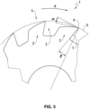
- Fig. 5 the conditions of a detailed section of a form milling head 1 are shown in a schematic side view.
- Line 5 represents a circumference line around the center of the form milling head 1.
- Fig. 4 It is clearly visible that the milling teeth 2 are not symmetrically constructed. Rather, they have a front side with a cutting edge area 6, whereby the cutting edge 6 forms the transition between surface 4 of the milling tooth 2 and its tooth face 7 (front side) when the form milling head 1 rotates in the direction of arrow A (machining direction).
- the tangential to the circular circumference line 5 at the cutting edge 6) would correspond to the surface of the workpiece to be machined. Accordingly, the angle between the tooth face 7 and the circular circumference line 5 at the cutting edge 6 forms the tooth face angle ⁇ during workpiece machining.
- the milling tooth 2 tapers so that between surface 4 of the milling tooth 2 and An increasing distance is created from the circumference line 5.
- the angle between the tangential line to the circumference line 5 and the tangential line to the surface 4 at the cutting edge 6 forms the so-called clearance angle ⁇ .
- the surface 4 of the milling teeth 2 is flat; the surface 4 of the milling teeth 2 thus forms a kind of "inclined plane.”
- the surface 4 of the milling teeth 2 is not flat and is designed, for example, as an inclined, slightly convex surface ("bump-like").
- the form milling head 1 If the form milling head 1 is used for material processing, it is naturally subject to a certain amount of wear, which is concentrated in the area of the cutting edge 6. Accordingly, a certain amount of material removal will also occur on the form milling head 1, particularly on the milling tooth 2. As a result, the cutting edge 6 deforms over time from a sharp edge (with a defined "true edge") to a "rounded” (and thus blunt) edge. Consequently, the form milling head 1 becomes blunt over time. This reduces its cutting performance. Furthermore, the surface machined by the form milling head 1 also exhibits a deterioration in quality.
- a sharp cutting edge 6 (with a "true edge") of the milling teeth 2 is once again achieved.
- This is achieved by a so-called regrinding process i.e., a grinding process in the area of the front side of the milling tooth 2 (seen in milling direction A).
- a portion of the tooth face 7 (a kind of "disk") is removed.
- a grinding wheel in particular a pointed grinding wheel 8, is generally used for this purpose.
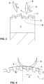
- Fig. 2 It is schematically indicated how the form milling head 1 can be ground several times in stages (“slice by slice”) in the area of the tooth face 7 during its life cycle.
- the combined regrinding/relief grinding process typically takes place in two steps. First, the regrinding process described above is performed (typically as the first step), i.e., the front side of milling tooth 2 (as seen in milling direction A) is ground.
- this step-like (disk-like) material removal in the area of the tooth face 7 "on its own” may no longer prove sufficient after extended use, especially with form milling heads.
- a milling tooth 2 can be seen in cross-section (the cross-section is perpendicular to the direction of movement of the milling tooth 2 during milling operation of the form milling head 1; i.e., the material processing direction).
- the surface structuring of the same can be seen in the form of a number of differently designed ridges 9 and grooves 10.
- the relief grinding process is carried out using a pointed grinding wheel 8, the protruding edge of which has a sufficiently small width so that the surface structuring of the surface 4 of the milling tooth 2 can be formed.
- the pointed grinding wheel 8 must be moved sideways back and forth and vertically up and down using a suitable travel pattern.
- the rotational axis 11 of the pointed grinding wheel 8 is inclined relative to the rotational axis of the form milling head 1.
- the edge areas of the grooves 10 can generally be better formed by such tilting/inclination of the pointed grinding wheel 8 relative to the form milling head 1.
- the relief grinding process is in addition to Fig. 3 also in Fig. 4 , shown here in a schematic plan view from the side.
- two different form lines/form points of the form milling head 1 are also shown, namely a web 9 and a Groove 10.
- the radially outer line represents a ridge 9 along the shape of the form milling head 1
- the radially inner line shows a groove 10 along the shape of the form milling head 1.
- the pointed grinding wheel 8 is also shown twice (i.e., in different positions).
- the individual regrinding and/or relief grinding cycles are naturally spaced apart in time. Between two regrinding and/or relief grinding processes, the form milling head 1 is typically used to mill the workpieces to be machined.
- a regrinding or relief grinding process can be performed over essentially its entire service life (and thus at varying degrees of wear of the form milling head 1), whereby the same pointed grinding wheel 8 can always be used.
- the number of "exclusive regrinding processes” material removal in the area of the tooth face 7) will be greater than the number of “combined regrinding and relief grinding processes” (both on the tooth face 7 and on the surface 4 of the milling teeth 2).
- the largest possible number of milling teeth 2, or in the circumferential direction of the form milling head 1 should be provided, because in this case a larger number of material removal processes occur during a single revolution of the form milling head 1 (a larger number of cutting edges 6 pass the workpiece to be machined).
- the number of teeth is also limited upwards (at least for practical reasons) (although usually without a sharp limit), since otherwise the dimensions of the tooth gaps 3 would be so small that the grinding process in the area of the tooth face 7 of the respective milling teeth 2 would have to be carried out with a too filigree tool (pointed grinding wheel 8) (compare Fig. 2 ).
- the number of grinding steps required would also increase too much, which would take a correspondingly long time.
- the rounded, determined number of teeth 2 for the form milling head 1 (after converting them to the tooth pitch y ) is incorporated into the aforementioned formula as an input parameter.
- the optimal diameter of the form milling head 1 is calculated (which is particularly easily possible using numerical solution methods). The deviations in diameter from the "desired diameter" are typically in the range of a few millimeters. The associated adverse effects are generally negligible.
Landscapes
- Engineering & Computer Science (AREA)
- Mechanical Engineering (AREA)
- Milling Processes (AREA)
Claims (6)
- Tête de fraisage (1) formée avec une pluralité de dents de fraisage (2) agissant pour la découpe, et d'interstices (3) interdentaires, qui sont agencés le long d'une surface circonférentielle (5) de la tête de fraisage (1),
dans laquelle le nombre de dents de fraisage (2) est plus grand et/ou substantiellement égal au nombre de dents de fraisage (2) déterminé en utilisant l'équation y = a · x3 + b · x 4 + c · x3 + d · x2 + e · x + f, où x est le diamètre de la tête de fraisage (1) en millimètres et y est le pas de dent, c'est-à-dire la distance entre deux dents de fraisage (2) adjacentes, en millimètres, et les plages de valeurs suivantes s'appliquent substantiellement aux paramètres a, b , c , d, e, et f :a se situe entre 1.95·10-9 et 2.05·10-9,b se situe entre -7.5·10-7 et -8.5·10-7,c se situe entre 0.95·10-4 et 1.05·10-4,d se situe entre 9.0·10-3 et d = 9.2·10-3,e se situe entre 3.1·10-1 et 3.2·10-1, etf se situe entre -2.0·10-1 et -2.1·10-1,caractérisée en ce que la tête de fraisage possède une forme de surface biseautée dont le profilé est constant ou respectivement logarithmique, le rapport entre la largeur des dents de fraisage et la largeur de l'espace interdentaire se situant dans une plage comprise entre 0,95 et 1,05, et la hauteur des dents de fraisage se situant dans une plage comprise entre 0,05 et 10 mm. - Tête de fraisage (1) selon la revendication 1, caractérisée en ce qu'un angle de coupe γ et/ou un angle de dégagement α de la dent de fraisage (2) reste substantiellement constant suite à un réaffutage et/ou suite au meulage des dents de fraisage (2).
- Tête de fraisage (1) selon l'une des revendications précédentes, caractérisée en ce que les dents de fraisage (2) sont agencées substantiellement selon le même espacement le long de la circonférence (5) de la tête de fraisage (1).
- Tête de fraisage (1) selon l'une des revendications 1 ou 2, caractérisée en ce que les dents de fraisage (2) sont disposées selon un espacement variable les unes par rapport aux autres le long de la circonférence (5) de la tête de fraisage (1).
- Tête de fraisage (1) selon l'une des revendications 1 à 4, caractérisée en ce que la tête de fraisage (1) est composée de carbure de tungstène et/ou de cobalt, du diamant et/ou du nitrure de bore pouvant être utilisés pour augmenter la dureté du matériau.
- Tête de fraisage (1) selon l'une des revendications 1 à 5, caractérisée en ce que la tête de fraisage (1) est conçue, agencée et dimensionnée de sorte qu'elle puisse être formée par meulage en utilisant une meule de plus de 60 mm de diamètre, l'axe de rotation de la tête de fraisage (1) et l'axe de rotation de la meule étant alignés de manière substantiellement parallèle l'un par rapport à l'autre.
Priority Applications (4)
| Application Number | Priority Date | Filing Date | Title |
|---|---|---|---|
| EP16199874.5A EP3323541B3 (fr) | 2016-11-21 | 2016-11-21 | Tête de fraisage logarithmique améliorée |
| US16/349,750 US11027340B2 (en) | 2016-11-21 | 2017-11-21 | Milling head with constant profiles |
| CN201780072009.5A CN110234455B (zh) | 2016-11-21 | 2017-11-21 | 改进的轮廓恒定的铣刀头 |
| PCT/EP2017/079955 WO2018091744A1 (fr) | 2016-11-21 | 2017-11-21 | Tête de fraisage à constante de profil améliorée |
Applications Claiming Priority (1)
| Application Number | Priority Date | Filing Date | Title |
|---|---|---|---|
| EP16199874.5A EP3323541B3 (fr) | 2016-11-21 | 2016-11-21 | Tête de fraisage logarithmique améliorée |
Publications (3)
| Publication Number | Publication Date |
|---|---|
| EP3323541A1 EP3323541A1 (fr) | 2018-05-23 |
| EP3323541B1 EP3323541B1 (fr) | 2019-06-19 |
| EP3323541B3 true EP3323541B3 (fr) | 2025-04-30 |
Family
ID=57389274
Family Applications (1)
| Application Number | Title | Priority Date | Filing Date |
|---|---|---|---|
| EP16199874.5A Active EP3323541B3 (fr) | 2016-11-21 | 2016-11-21 | Tête de fraisage logarithmique améliorée |
Country Status (4)
| Country | Link |
|---|---|
| US (1) | US11027340B2 (fr) |
| EP (1) | EP3323541B3 (fr) |
| CN (1) | CN110234455B (fr) |
| WO (1) | WO2018091744A1 (fr) |
Families Citing this family (2)
| Publication number | Priority date | Publication date | Assignee | Title |
|---|---|---|---|---|
| CN109736379B (zh) * | 2019-01-21 | 2023-09-01 | 江苏徐工工程机械研究院有限公司 | 一种用于地下连续墙开挖的铣轮及双轮铣槽机 |
| DE202024001323U1 (de) | 2024-07-12 | 2024-09-03 | Adalbert Liedtke Gesellschaft mit beschränkter Haftung | Fräswerkzeug mit speziell ausgebildeter Spankammer für die Schlüsselbearbeitung |
Family Cites Families (9)
| Publication number | Priority date | Publication date | Assignee | Title |
|---|---|---|---|---|
| FR678321A (fr) * | 1929-07-11 | 1930-03-21 | Perfectionnements aux fraises à profil constant | |
| DE10163040C1 (de) * | 2001-12-21 | 2003-08-21 | Daimler Chrysler Ag | Werkzeug zum Herstellen eines Gelenkinnenteils für ein Gleichlaufdrehgelenk |
| SE0600406L (sv) * | 2006-02-22 | 2007-08-14 | Seco Tools Ab | Roterbart frässkär för gängfräsning tillverkat av kubisk bornitrid samt gängfräsverktyg |
| CN101637829B (zh) * | 2009-08-04 | 2011-06-08 | 福建金鑫钨业股份有限公司 | 硬质合金冷作模压坯油槽铣刀 |
| SE535941C2 (sv) * | 2011-06-20 | 2013-02-26 | Sandvik Intellectual Property | Fräsverktyg för hobbning samt segment härför |
| CN103381499B (zh) * | 2012-05-03 | 2016-12-14 | 李仕清 | 一种复合铣刀 |
| SE537377C2 (sv) * | 2012-07-05 | 2015-04-14 | Sandvik Intellectual Property | Skärinsats och fräsverktyg för fräsning av ett spår i ett arbetsstycke |
| CN103331473B (zh) * | 2013-05-17 | 2015-10-28 | 西安交通大学 | 一种超密齿面铣刀及其设计方法 |
| CN104889466A (zh) * | 2015-06-11 | 2015-09-09 | 山东大学 | 整体式全陶瓷超密齿三面刃铣刀及其制造方法 |
-
2016
- 2016-11-21 EP EP16199874.5A patent/EP3323541B3/fr active Active
-
2017
- 2017-11-21 WO PCT/EP2017/079955 patent/WO2018091744A1/fr not_active Ceased
- 2017-11-21 CN CN201780072009.5A patent/CN110234455B/zh active Active
- 2017-11-21 US US16/349,750 patent/US11027340B2/en active Active
Also Published As
| Publication number | Publication date |
|---|---|
| CN110234455A (zh) | 2019-09-13 |
| WO2018091744A1 (fr) | 2018-05-24 |
| US20200070257A1 (en) | 2020-03-05 |
| CN110234455B (zh) | 2021-01-05 |
| EP3323541A1 (fr) | 2018-05-23 |
| US11027340B2 (en) | 2021-06-08 |
| EP3323541B1 (fr) | 2019-06-19 |
Similar Documents
| Publication | Publication Date | Title |
|---|---|---|
| DE102015105216B4 (de) | Fräser mit verbesserter Spanabfuhrfähigkeit und Verfahren zu dessen Herstellung | |
| DE69412643T2 (de) | Verfahren zur herstellung von befestigungsnuten für turbinenschaufeln | |
| DE102016206721A1 (de) | Schneidwerkzeug zur verbesserten Spanabfuhr und Verfahren zu dessen Herstellung | |
| EP1511590B1 (fr) | Fraise avec rayon de surfaçage | |
| DE202011050054U1 (de) | Wälzschälwerkzeug mit Messerstäben | |
| EP3694670B1 (fr) | Outil de taillage en développante | |
| DE29810969U1 (de) | Schneideinsatz, Schneidwerkzeug zur spanenden Bearbeitung, insbesondere von rotationssymmetrischen Werkstückflächen | |
| EP3530389A1 (fr) | Fraiseuse | |
| DE102019135435A1 (de) | Werkzeug und Verfahren zur spanenden Bearbeitung eines Werkstücks | |
| EP3481575A1 (fr) | Outil d'usinage de dentures, en forme de roue, procédé d'usinage de dentures, procédé d'aiguisage un outil d'usinage de dentures et machine d'usinage de dentures | |
| EP3323541B1 (fr) | Tête de fraisage logarithmique améliorée | |
| DE102004022360B4 (de) | Verfahren zur Feinbearbeitung, vorzugsweise zur Feinstschlichtbearbeitung, von Werkstücken vorzugsweise von Kurbelwellen | |
| DE102016101525B4 (de) | Verfahren zur Bearbeitung einer Werkzeugkante eines Zerspanwerkzeugs und Bürstschleifmaschine | |
| EP3110364B1 (fr) | Instrument dentaire | |
| EP1927444A2 (fr) | Lame de rabot | |
| DE19626608B4 (de) | Verfahren zur spanenden Bearbeitung | |
| DE102010045836A1 (de) | Vorrichtung und Verfahren zur Herstellung eines Abrichtwerkzeuges mit Vertiefungen | |
| EP2388095B2 (fr) | Outil de fraisage | |
| DE102015223428B4 (de) | Trennschleifscheibe, Verwendung einer Trennschleifscheibe sowie Verfahren zum Trennen eines Werkstückes mittels Trennschleifen | |
| EP2801431A1 (fr) | Procédé de traitement d'une lame de scie et affûteuse à lames de scies | |
| CH705571B1 (de) | Fräswerkzeug. | |
| DE10324432B4 (de) | Profilgeschärftes Stabmesser zur Herstellung von Kegel- und Hypoidrädern und Verfahren zum Profilschärfen eines solchen Stabmessers | |
| EP1350587B1 (fr) | Lame de coupe sous forme de barre, utilisation et procédé de traitement | |
| DE2539881A1 (de) | Zahnaerztliches drehwerkzeug, insbesondere fraeser | |
| DE202005018963U1 (de) | Fräsmesserkopf |
Legal Events
| Date | Code | Title | Description |
|---|---|---|---|
| PUAI | Public reference made under article 153(3) epc to a published international application that has entered the european phase |
Free format text: ORIGINAL CODE: 0009012 |
|
| STAA | Information on the status of an ep patent application or granted ep patent |
Free format text: STATUS: THE APPLICATION HAS BEEN PUBLISHED |
|
| AK | Designated contracting states |
Kind code of ref document: A1 Designated state(s): AL AT BE BG CH CY CZ DE DK EE ES FI FR GB GR HR HU IE IS IT LI LT LU LV MC MK MT NL NO PL PT RO RS SE SI SK SM TR |
|
| AX | Request for extension of the european patent |
Extension state: BA ME |
|
| STAA | Information on the status of an ep patent application or granted ep patent |
Free format text: STATUS: REQUEST FOR EXAMINATION WAS MADE |
|
| 17P | Request for examination filed |
Effective date: 20180820 |
|
| RBV | Designated contracting states (corrected) |
Designated state(s): AL AT BE BG CH CY CZ DE DK EE ES FI FR GB GR HR HU IE IS IT LI LT LU LV MC MK MT NL NO PL PT RO RS SE SI SK SM TR |
|
| GRAP | Despatch of communication of intention to grant a patent |
Free format text: ORIGINAL CODE: EPIDOSNIGR1 |
|
| STAA | Information on the status of an ep patent application or granted ep patent |
Free format text: STATUS: GRANT OF PATENT IS INTENDED |
|
| INTG | Intention to grant announced |
Effective date: 20190124 |
|
| GRAS | Grant fee paid |
Free format text: ORIGINAL CODE: EPIDOSNIGR3 |
|
| GRAA | (expected) grant |
Free format text: ORIGINAL CODE: 0009210 |
|
| STAA | Information on the status of an ep patent application or granted ep patent |
Free format text: STATUS: THE PATENT HAS BEEN GRANTED |
|
| AK | Designated contracting states |
Kind code of ref document: B1 Designated state(s): AL AT BE BG CH CY CZ DE DK EE ES FI FR GB GR HR HU IE IS IT LI LT LU LV MC MK MT NL NO PL PT RO RS SE SI SK SM TR |
|
| REG | Reference to a national code |
Ref country code: GB Ref legal event code: FG4D Free format text: NOT ENGLISH |
|
| REG | Reference to a national code |
Ref country code: CH Ref legal event code: EP Ref country code: CH Ref legal event code: NV Representative=s name: BOVARD AG PATENT- UND MARKENANWAELTE, CH |
|
| REG | Reference to a national code |
Ref country code: IE Ref legal event code: FG4D Free format text: LANGUAGE OF EP DOCUMENT: GERMAN |
|
| REG | Reference to a national code |
Ref country code: DE Ref legal event code: R096 Ref document number: 502016005125 Country of ref document: DE |
|
| REG | Reference to a national code |
Ref country code: AT Ref legal event code: REF Ref document number: 1144855 Country of ref document: AT Kind code of ref document: T Effective date: 20190715 |
|
| REG | Reference to a national code |
Ref country code: NL Ref legal event code: MP Effective date: 20190619 |
|
| PG25 | Lapsed in a contracting state [announced via postgrant information from national office to epo] |
Ref country code: NO Free format text: LAPSE BECAUSE OF FAILURE TO SUBMIT A TRANSLATION OF THE DESCRIPTION OR TO PAY THE FEE WITHIN THE PRESCRIBED TIME-LIMIT Effective date: 20190919 Ref country code: FI Free format text: LAPSE BECAUSE OF FAILURE TO SUBMIT A TRANSLATION OF THE DESCRIPTION OR TO PAY THE FEE WITHIN THE PRESCRIBED TIME-LIMIT Effective date: 20190619 Ref country code: LT Free format text: LAPSE BECAUSE OF FAILURE TO SUBMIT A TRANSLATION OF THE DESCRIPTION OR TO PAY THE FEE WITHIN THE PRESCRIBED TIME-LIMIT Effective date: 20190619 Ref country code: HR Free format text: LAPSE BECAUSE OF FAILURE TO SUBMIT A TRANSLATION OF THE DESCRIPTION OR TO PAY THE FEE WITHIN THE PRESCRIBED TIME-LIMIT Effective date: 20190619 Ref country code: SE Free format text: LAPSE BECAUSE OF FAILURE TO SUBMIT A TRANSLATION OF THE DESCRIPTION OR TO PAY THE FEE WITHIN THE PRESCRIBED TIME-LIMIT Effective date: 20190619 Ref country code: AL Free format text: LAPSE BECAUSE OF FAILURE TO SUBMIT A TRANSLATION OF THE DESCRIPTION OR TO PAY THE FEE WITHIN THE PRESCRIBED TIME-LIMIT Effective date: 20190619 |
|
| REG | Reference to a national code |
Ref country code: LT Ref legal event code: MG4D |
|
| PG25 | Lapsed in a contracting state [announced via postgrant information from national office to epo] |
Ref country code: GR Free format text: LAPSE BECAUSE OF FAILURE TO SUBMIT A TRANSLATION OF THE DESCRIPTION OR TO PAY THE FEE WITHIN THE PRESCRIBED TIME-LIMIT Effective date: 20190920 Ref country code: LV Free format text: LAPSE BECAUSE OF FAILURE TO SUBMIT A TRANSLATION OF THE DESCRIPTION OR TO PAY THE FEE WITHIN THE PRESCRIBED TIME-LIMIT Effective date: 20190619 Ref country code: RS Free format text: LAPSE BECAUSE OF FAILURE TO SUBMIT A TRANSLATION OF THE DESCRIPTION OR TO PAY THE FEE WITHIN THE PRESCRIBED TIME-LIMIT Effective date: 20190619 Ref country code: BG Free format text: LAPSE BECAUSE OF FAILURE TO SUBMIT A TRANSLATION OF THE DESCRIPTION OR TO PAY THE FEE WITHIN THE PRESCRIBED TIME-LIMIT Effective date: 20190919 |
|
| PG25 | Lapsed in a contracting state [announced via postgrant information from national office to epo] |
Ref country code: RO Free format text: LAPSE BECAUSE OF FAILURE TO SUBMIT A TRANSLATION OF THE DESCRIPTION OR TO PAY THE FEE WITHIN THE PRESCRIBED TIME-LIMIT Effective date: 20190619 Ref country code: CZ Free format text: LAPSE BECAUSE OF FAILURE TO SUBMIT A TRANSLATION OF THE DESCRIPTION OR TO PAY THE FEE WITHIN THE PRESCRIBED TIME-LIMIT Effective date: 20190619 Ref country code: SK Free format text: LAPSE BECAUSE OF FAILURE TO SUBMIT A TRANSLATION OF THE DESCRIPTION OR TO PAY THE FEE WITHIN THE PRESCRIBED TIME-LIMIT Effective date: 20190619 Ref country code: NL Free format text: LAPSE BECAUSE OF FAILURE TO SUBMIT A TRANSLATION OF THE DESCRIPTION OR TO PAY THE FEE WITHIN THE PRESCRIBED TIME-LIMIT Effective date: 20190619 Ref country code: PT Free format text: LAPSE BECAUSE OF FAILURE TO SUBMIT A TRANSLATION OF THE DESCRIPTION OR TO PAY THE FEE WITHIN THE PRESCRIBED TIME-LIMIT Effective date: 20191021 Ref country code: EE Free format text: LAPSE BECAUSE OF FAILURE TO SUBMIT A TRANSLATION OF THE DESCRIPTION OR TO PAY THE FEE WITHIN THE PRESCRIBED TIME-LIMIT Effective date: 20190619 |
|
| PG25 | Lapsed in a contracting state [announced via postgrant information from national office to epo] |
Ref country code: ES Free format text: LAPSE BECAUSE OF FAILURE TO SUBMIT A TRANSLATION OF THE DESCRIPTION OR TO PAY THE FEE WITHIN THE PRESCRIBED TIME-LIMIT Effective date: 20190619 Ref country code: SM Free format text: LAPSE BECAUSE OF FAILURE TO SUBMIT A TRANSLATION OF THE DESCRIPTION OR TO PAY THE FEE WITHIN THE PRESCRIBED TIME-LIMIT Effective date: 20190619 Ref country code: IS Free format text: LAPSE BECAUSE OF FAILURE TO SUBMIT A TRANSLATION OF THE DESCRIPTION OR TO PAY THE FEE WITHIN THE PRESCRIBED TIME-LIMIT Effective date: 20191019 |
|
| PG25 | Lapsed in a contracting state [announced via postgrant information from national office to epo] |
Ref country code: TR Free format text: LAPSE BECAUSE OF FAILURE TO SUBMIT A TRANSLATION OF THE DESCRIPTION OR TO PAY THE FEE WITHIN THE PRESCRIBED TIME-LIMIT Effective date: 20190619 |
|
| PG25 | Lapsed in a contracting state [announced via postgrant information from national office to epo] |
Ref country code: PL Free format text: LAPSE BECAUSE OF FAILURE TO SUBMIT A TRANSLATION OF THE DESCRIPTION OR TO PAY THE FEE WITHIN THE PRESCRIBED TIME-LIMIT Effective date: 20190619 Ref country code: DK Free format text: LAPSE BECAUSE OF FAILURE TO SUBMIT A TRANSLATION OF THE DESCRIPTION OR TO PAY THE FEE WITHIN THE PRESCRIBED TIME-LIMIT Effective date: 20190619 |
|
| PG25 | Lapsed in a contracting state [announced via postgrant information from national office to epo] |
Ref country code: IS Free format text: LAPSE BECAUSE OF FAILURE TO SUBMIT A TRANSLATION OF THE DESCRIPTION OR TO PAY THE FEE WITHIN THE PRESCRIBED TIME-LIMIT Effective date: 20200224 |
|
| REG | Reference to a national code |
Ref country code: DE Ref legal event code: R097 Ref document number: 502016005125 Country of ref document: DE |
|
| PLBE | No opposition filed within time limit |
Free format text: ORIGINAL CODE: 0009261 |
|
| STAA | Information on the status of an ep patent application or granted ep patent |
Free format text: STATUS: NO OPPOSITION FILED WITHIN TIME LIMIT |
|
| PG2D | Information on lapse in contracting state deleted |
Ref country code: IS |
|
| PG25 | Lapsed in a contracting state [announced via postgrant information from national office to epo] |
Ref country code: MC Free format text: LAPSE BECAUSE OF FAILURE TO SUBMIT A TRANSLATION OF THE DESCRIPTION OR TO PAY THE FEE WITHIN THE PRESCRIBED TIME-LIMIT Effective date: 20190619 Ref country code: LU Free format text: LAPSE BECAUSE OF NON-PAYMENT OF DUE FEES Effective date: 20191121 |
|
| 26N | No opposition filed |
Effective date: 20200603 |
|
| REG | Reference to a national code |
Ref country code: BE Ref legal event code: MM Effective date: 20191130 |
|
| PG25 | Lapsed in a contracting state [announced via postgrant information from national office to epo] |
Ref country code: SI Free format text: LAPSE BECAUSE OF FAILURE TO SUBMIT A TRANSLATION OF THE DESCRIPTION OR TO PAY THE FEE WITHIN THE PRESCRIBED TIME-LIMIT Effective date: 20190619 |
|
| PG25 | Lapsed in a contracting state [announced via postgrant information from national office to epo] |
Ref country code: IE Free format text: LAPSE BECAUSE OF NON-PAYMENT OF DUE FEES Effective date: 20191121 |
|
| PG25 | Lapsed in a contracting state [announced via postgrant information from national office to epo] |
Ref country code: BE Free format text: LAPSE BECAUSE OF NON-PAYMENT OF DUE FEES Effective date: 20191130 |
|
| PG25 | Lapsed in a contracting state [announced via postgrant information from national office to epo] |
Ref country code: CY Free format text: LAPSE BECAUSE OF FAILURE TO SUBMIT A TRANSLATION OF THE DESCRIPTION OR TO PAY THE FEE WITHIN THE PRESCRIBED TIME-LIMIT Effective date: 20190619 |
|
| GBPC | Gb: european patent ceased through non-payment of renewal fee |
Effective date: 20201121 |
|
| PG25 | Lapsed in a contracting state [announced via postgrant information from national office to epo] |
Ref country code: HU Free format text: LAPSE BECAUSE OF FAILURE TO SUBMIT A TRANSLATION OF THE DESCRIPTION OR TO PAY THE FEE WITHIN THE PRESCRIBED TIME-LIMIT; INVALID AB INITIO Effective date: 20161121 Ref country code: MT Free format text: LAPSE BECAUSE OF FAILURE TO SUBMIT A TRANSLATION OF THE DESCRIPTION OR TO PAY THE FEE WITHIN THE PRESCRIBED TIME-LIMIT Effective date: 20190619 |
|
| PG25 | Lapsed in a contracting state [announced via postgrant information from national office to epo] |
Ref country code: GB Free format text: LAPSE BECAUSE OF NON-PAYMENT OF DUE FEES Effective date: 20201121 |
|
| REG | Reference to a national code |
Ref country code: DE Ref legal event code: R055 Ref document number: 502016005125 Country of ref document: DE |
|
| PLCP | Request for limitation filed |
Free format text: ORIGINAL CODE: EPIDOSNLIM1 |
|
| PLCQ | Request for limitation of patent found admissible |
Free format text: ORIGINAL CODE: 0009231 |
|
| LIM1 | Request for limitation found admissible |
Free format text: SEQUENCE NO: 1; FILED AFTER OPPOSITION PERIOD Filing date: 20211216 Effective date: 20211216 |
|
| PG25 | Lapsed in a contracting state [announced via postgrant information from national office to epo] |
Ref country code: MK Free format text: LAPSE BECAUSE OF FAILURE TO SUBMIT A TRANSLATION OF THE DESCRIPTION OR TO PAY THE FEE WITHIN THE PRESCRIBED TIME-LIMIT Effective date: 20190619 |
|
| PLBY | Limitation procedure: information modified related to despatch of communication from examining division + time limit |
Free format text: ORIGINAL CODE: EPIDOSCLIR2 |
|
| PLBV | Information modified related to decision on request for limitation of patent |
Free format text: ORIGINAL CODE: 0009299LIMP |
|
| LIM5 | Request for limitation withdrawn |
Free format text: SEQUENCE NO: 1; FILED AFTER OPPOSITION PERIOD; CHANGE OF DECISION ON REQUEST FOR LIMITATION OF PATENT Filing date: 20211216 Effective date: 20211216 |
|
| REG | Reference to a national code |
Ref country code: AT Ref legal event code: MM01 Ref document number: 1144855 Country of ref document: AT Kind code of ref document: T Effective date: 20211121 |
|
| PG25 | Lapsed in a contracting state [announced via postgrant information from national office to epo] |
Ref country code: AT Free format text: LAPSE BECAUSE OF NON-PAYMENT OF DUE FEES Effective date: 20211121 |
|
| PLCP | Request for limitation filed |
Free format text: ORIGINAL CODE: EPIDOSNLIM1 |
|
| PLCQ | Request for limitation of patent found admissible |
Free format text: ORIGINAL CODE: 0009231 |
|
| LIM1 | Request for limitation found admissible |
Free format text: SEQUENCE NO: 2; FILED AFTER OPPOSITION PERIOD Filing date: 20240823 Effective date: 20240823 |
|
| LIM5 | Request for limitation withdrawn |
Free format text: SEQUENCE NO: 1; FILED AFTER OPPOSITION PERIOD Filing date: 20211216 Effective date: 20211216 |
|
| PLCO | Limitation procedure: reply received to communication from examining division + time limit |
Free format text: ORIGINAL CODE: EPIDOSNLIR3 |
|
| PLCR | Communication despatched that request for limitation of patent was allowed |
Free format text: ORIGINAL CODE: 0009245 |
|
| REG | Reference to a national code |
Ref country code: DE Ref legal event code: R056 Ref document number: 502016005125 Country of ref document: DE |
|
| PUAM | (expected) publication of b3 document |
Free format text: ORIGINAL CODE: 0009410 |
|
| STAA | Information on the status of an ep patent application or granted ep patent |
Free format text: STATUS: THE PATENT HAS BEEN LIMITED |
|
| REG | Reference to a national code |
Ref country code: CH Ref legal event code: U11 Free format text: ST27 STATUS EVENT CODE: U-0-0-U10-U11 (AS PROVIDED BY THE NATIONAL OFFICE) Effective date: 20251201 |
|
| PGFP | Annual fee paid to national office [announced via postgrant information from national office to epo] |
Ref country code: DE Payment date: 20251119 Year of fee payment: 10 |
|
| PGFP | Annual fee paid to national office [announced via postgrant information from national office to epo] |
Ref country code: IT Payment date: 20251121 Year of fee payment: 10 |
|
| PGFP | Annual fee paid to national office [announced via postgrant information from national office to epo] |
Ref country code: FR Payment date: 20251126 Year of fee payment: 10 |
|
| PGFP | Annual fee paid to national office [announced via postgrant information from national office to epo] |
Ref country code: CH Payment date: 20251201 Year of fee payment: 10 |