EP3323565A1 - Procédé et dispositif de mise en service d'un système multiaxial - Google Patents
Procédé et dispositif de mise en service d'un système multiaxial Download PDFInfo
- Publication number
- EP3323565A1 EP3323565A1 EP16199731.7A EP16199731A EP3323565A1 EP 3323565 A1 EP3323565 A1 EP 3323565A1 EP 16199731 A EP16199731 A EP 16199731A EP 3323565 A1 EP3323565 A1 EP 3323565A1
- Authority
- EP
- European Patent Office
- Prior art keywords
- axis system
- axis
- camera
- components
- markers
- Prior art date
- Legal status (The legal status is an assumption and is not a legal conclusion. Google has not performed a legal analysis and makes no representation as to the accuracy of the status listed.)
- Granted
Links
Images
Classifications
-
- G—PHYSICS
- G06—COMPUTING OR CALCULATING; COUNTING
- G06T—IMAGE DATA PROCESSING OR GENERATION, IN GENERAL
- G06T7/00—Image analysis
- G06T7/0002—Inspection of images, e.g. flaw detection
- G06T7/0004—Industrial image inspection
-
- B—PERFORMING OPERATIONS; TRANSPORTING
- B25—HAND TOOLS; PORTABLE POWER-DRIVEN TOOLS; MANIPULATORS
- B25J—MANIPULATORS; CHAMBERS PROVIDED WITH MANIPULATION DEVICES
- B25J9/00—Program-controlled manipulators
- B25J9/16—Program controls
- B25J9/1656—Program controls characterised by programming, planning systems for manipulators
- B25J9/1664—Program controls characterised by programming, planning systems for manipulators characterised by motion, path, trajectory planning
- B25J9/1666—Avoiding collision or forbidden zones
-
- B—PERFORMING OPERATIONS; TRANSPORTING
- B25—HAND TOOLS; PORTABLE POWER-DRIVEN TOOLS; MANIPULATORS
- B25J—MANIPULATORS; CHAMBERS PROVIDED WITH MANIPULATION DEVICES
- B25J9/00—Program-controlled manipulators
- B25J9/16—Program controls
-
- B—PERFORMING OPERATIONS; TRANSPORTING
- B25—HAND TOOLS; PORTABLE POWER-DRIVEN TOOLS; MANIPULATORS
- B25J—MANIPULATORS; CHAMBERS PROVIDED WITH MANIPULATION DEVICES
- B25J9/00—Program-controlled manipulators
- B25J9/16—Program controls
- B25J9/1656—Program controls characterised by programming, planning systems for manipulators
- B25J9/1671—Program controls characterised by programming, planning systems for manipulators characterised by simulation, either to verify existing program or to create and verify new program, CAD/CAM oriented, graphic oriented programming systems
-
- G—PHYSICS
- G05—CONTROLLING; REGULATING
- G05B—CONTROL OR REGULATING SYSTEMS IN GENERAL; FUNCTIONAL ELEMENTS OF SUCH SYSTEMS; MONITORING OR TESTING ARRANGEMENTS FOR SUCH SYSTEMS OR ELEMENTS
- G05B19/00—Program-control systems
- G05B19/02—Program-control systems electric
- G05B19/04—Program control other than numerical control, i.e. in sequence controllers or logic controllers
- G05B19/05—Programmable logic controllers, e.g. simulating logic interconnections of signals according to ladder diagrams or function charts
- G05B19/058—Safety, monitoring
-
- G—PHYSICS
- G05—CONTROLLING; REGULATING
- G05B—CONTROL OR REGULATING SYSTEMS IN GENERAL; FUNCTIONAL ELEMENTS OF SUCH SYSTEMS; MONITORING OR TESTING ARRANGEMENTS FOR SUCH SYSTEMS OR ELEMENTS
- G05B19/00—Program-control systems
- G05B19/02—Program-control systems electric
- G05B19/18—Numerical control [NC], i.e. automatically operating machines, in particular machine tools, e.g. in a manufacturing environment, so as to execute positioning, movement or co-ordinated operations by means of program data in numerical form
- G05B19/414—Structure of the control system, e.g. common controller or multiprocessor systems, interface to servo, programmable interface controller
-
- G—PHYSICS
- G06—COMPUTING OR CALCULATING; COUNTING
- G06T—IMAGE DATA PROCESSING OR GENERATION, IN GENERAL
- G06T19/00—Manipulating three-dimensional [3D] models or images for computer graphics
- G06T19/006—Mixed reality
-
- G—PHYSICS
- G06—COMPUTING OR CALCULATING; COUNTING
- G06T—IMAGE DATA PROCESSING OR GENERATION, IN GENERAL
- G06T7/00—Image analysis
- G06T7/20—Analysis of motion
-
- G—PHYSICS
- G06—COMPUTING OR CALCULATING; COUNTING
- G06T—IMAGE DATA PROCESSING OR GENERATION, IN GENERAL
- G06T7/00—Image analysis
- G06T7/50—Depth or shape recovery
-
- G—PHYSICS
- G06—COMPUTING OR CALCULATING; COUNTING
- G06T—IMAGE DATA PROCESSING OR GENERATION, IN GENERAL
- G06T7/00—Image analysis
- G06T7/70—Determining position or orientation of objects or cameras
- G06T7/73—Determining position or orientation of objects or cameras using feature-based methods
-
- G—PHYSICS
- G05—CONTROLLING; REGULATING
- G05B—CONTROL OR REGULATING SYSTEMS IN GENERAL; FUNCTIONAL ELEMENTS OF SUCH SYSTEMS; MONITORING OR TESTING ARRANGEMENTS FOR SUCH SYSTEMS OR ELEMENTS
- G05B2219/00—Program-control systems
- G05B2219/10—Plc systems
- G05B2219/13—Plc programming
- G05B2219/13098—Nc function to control axis, written in C or not
-
- G—PHYSICS
- G05—CONTROLLING; REGULATING
- G05B—CONTROL OR REGULATING SYSTEMS IN GENERAL; FUNCTIONAL ELEMENTS OF SUCH SYSTEMS; MONITORING OR TESTING ARRANGEMENTS FOR SUCH SYSTEMS OR ELEMENTS
- G05B2219/00—Program-control systems
- G05B2219/30—Nc systems
- G05B2219/32—Operator till task planning
- G05B2219/32014—Augmented reality assists operator in maintenance, repair, programming, assembly, use of head mounted display with 2-D 3-D display and voice feedback, voice and gesture command
-
- G—PHYSICS
- G05—CONTROLLING; REGULATING
- G05B—CONTROL OR REGULATING SYSTEMS IN GENERAL; FUNCTIONAL ELEMENTS OF SUCH SYSTEMS; MONITORING OR TESTING ARRANGEMENTS FOR SUCH SYSTEMS OR ELEMENTS
- G05B2219/00—Program-control systems
- G05B2219/30—Nc systems
- G05B2219/37—Measurements
- G05B2219/37009—Calibration of vision system, camera, adapt light level
-
- G—PHYSICS
- G05—CONTROLLING; REGULATING
- G05B—CONTROL OR REGULATING SYSTEMS IN GENERAL; FUNCTIONAL ELEMENTS OF SUCH SYSTEMS; MONITORING OR TESTING ARRANGEMENTS FOR SUCH SYSTEMS OR ELEMENTS
- G05B2219/00—Program-control systems
- G05B2219/30—Nc systems
- G05B2219/39—Robotics, robotics to robotics hand
- G05B2219/39094—Interference checking between robot and fixture
-
- G—PHYSICS
- G05—CONTROLLING; REGULATING
- G05B—CONTROL OR REGULATING SYSTEMS IN GENERAL; FUNCTIONAL ELEMENTS OF SUCH SYSTEMS; MONITORING OR TESTING ARRANGEMENTS FOR SUCH SYSTEMS OR ELEMENTS
- G05B2219/00—Program-control systems
- G05B2219/30—Nc systems
- G05B2219/39—Robotics, robotics to robotics hand
- G05B2219/39449—Pendant, pda displaying camera images overlayed with graphics, augmented reality
-
- G—PHYSICS
- G05—CONTROLLING; REGULATING
- G05B—CONTROL OR REGULATING SYSTEMS IN GENERAL; FUNCTIONAL ELEMENTS OF SUCH SYSTEMS; MONITORING OR TESTING ARRANGEMENTS FOR SUCH SYSTEMS OR ELEMENTS
- G05B2219/00—Program-control systems
- G05B2219/30—Nc systems
- G05B2219/40—Robotics, robotics mapping to robotics vision
- G05B2219/40479—Use graphic display, layout of robot path, obstacles to indicate interference
-
- G—PHYSICS
- G06—COMPUTING OR CALCULATING; COUNTING
- G06T—IMAGE DATA PROCESSING OR GENERATION, IN GENERAL
- G06T2207/00—Indexing scheme for image analysis or image enhancement
- G06T2207/30—Subject of image; Context of image processing
- G06T2207/30108—Industrial image inspection
- G06T2207/30164—Workpiece; Machine component
-
- G—PHYSICS
- G06—COMPUTING OR CALCULATING; COUNTING
- G06T—IMAGE DATA PROCESSING OR GENERATION, IN GENERAL
- G06T2207/00—Indexing scheme for image analysis or image enhancement
- G06T2207/30—Subject of image; Context of image processing
- G06T2207/30204—Marker
- G06T2207/30208—Marker matrix
-
- G—PHYSICS
- G06—COMPUTING OR CALCULATING; COUNTING
- G06T—IMAGE DATA PROCESSING OR GENERATION, IN GENERAL
- G06T2210/00—Indexing scheme for image generation or computer graphics
- G06T2210/12—Bounding box
Definitions
- the invention relates to a method and a device for starting up a multi-axis system.
- the multi-axis system includes as components a number of segments connected by respective hinges and movable in one or more axes, and a tool connected to one of the segments and movable and controllable to a predetermined position.
- the multi-axis system is a work space in which a residence and / or movement of the components is allowed, and associated with at least one shelter in which an intrusion of the components is not allowed.
- Multi-axis systems are universal, programmable machines for handling, assembling or machining workpieces. These are also called (industrial) robots. These are designed for use in industrial environments. Once programmed, such a multi-axis system is able to autonomously perform a workflow, or to vary the execution of a task, depending on sensor information.
- a prerequisite for the correct and safe functioning of such a multi-axis system is the definition of enveloping bodies for the moving components as well as the correct definition of protective and working spaces.
- Envelopes may have different geometric dimensions and shapes.
- Typical enveloping bodies used are e.g. Spheres, cuboids or structures composed of several cuboids.
- the definition of enveloping bodies as well as the definition of protective and working spaces enables a cooperation of a multi-axis system with humans, as long as it is ensured that no enveloping body of a component of the multi-axis system penetrates into a shelter. Failure to define these bodies will result in e.g. the penetration of an enveloping body into a protected area is not recognized, so that a safety function is erroneously not triggered.
- a method for starting up a multi-axis system includes as components a number of segments and a tool.
- the number of segments is connected in pairs via respective joints and is movable by a control in one or more axes.
- the tool is connected to one of the segments and moved by the controller to a predetermined position and controllable.
- the multi-axis system is assigned a workspace in which a residence and / or movement of the components of the multi-axis system is permitted. Further, the multi-axis system is associated with at least one shelter in which an intrusion of the components is not allowed.
- a plurality of optical markers are arranged in the environment of the multi-axis system to enable an augmented reality (AR) system, the position and orientation of a camera system comprising at least one camera and the multi-axis system detected from an environment to determine.
- AR augmented reality
- a camera system comprising at least one camera
- the multi-axis system detected from an environment to determine.
- an enveloping body is defined and assigned thereto, wherein an enveloping body assigned to a component encloses the associated component, in particular completely.
- a check of the defined enveloping body with respect to the working space and the shelter by means of the AR system is performed by calculating the position of the enveloping bodies in a first, global coordinate system (world coordinate system) and in a second coordinate system during a movement of the multi-axis system in space a position and orientation of the camera system (camera coordinate system) is transformed, wherein the enveloping bodies transformed into the second coordinate system are visualized together with an image captured by the camera system in the AR system.
- the proposed method enables a functionally secure definition and verification of the enveloping body as well as the protective and working areas with the aid of the AR system. Any errors in the definition of the enveloping body or in the assignment of an enveloping body to a respective component of the multi-axis system can be detected in a simple and rapid manner by the possibility of visual checking in the AR system. In addition, the proposed method is less prone to errors of reasoning.
- position coordinates of the optical markers in the first global coordinate system are determined and stored in the controller.
- the Determining the position coordinates can be done in different ways.
- a TCP (Tool Center Point) of the tool of the multi-axis system is moved to a respective optical marker to determine the position coordinates of the optical markers. Further, the position coordinates of the TCP known to the controller are determined and stored as the position coordinates of the optical marker.
- the tool in particular with its TCP, is moved to the location of the optical marker. This movement can be done manually in a so-called jogging mode or automatically. Since the control of the multi-axis system in a manual or automatic movement of the tool knows the position coordinates of the tool or its TCP, the position of the optical marker and its position coordinates can be determined.
- a mark applied to the tool, in particular the TCP, and the optical marker currently being processed are detected by the AR system.
- a distance between the marker and the optical marker is determined.
- the position of the tool is iteratively changed until the distance is minimal.
- the position coordinates known to the controller of the tool, in particular of the TCP are determined and stored at a minimum distance as the position coordinates of the optical marker.
- the TCP is a reference point intended in the field of multi-axis systems and known to the person skilled in the art, which is located at a suitable location on the tool. To describe the position of the multi-axis system tool, it is sufficient to define the position and orientation of the TCP in space, ie in the global coordinate system.
- the second variant for determining the position coordinates makes it possible to automatically determine the position coordinates of the respective optical markers.
- An iterative search method is used in which the tool or the TCP is moved until the distance between the tool or TCP and the currently considered optical marker becomes minimal. This procedure is repeated for all optical markers.
- the mark attached to the tool or TCP may be an optical mark which is visually detectable by the AR system.
- the marking may alternatively be a distance measuring unit. This can e.g. a laser gauge that measures the distance to a point in front of it. This may, for example, include a radio interface to transmit a distance measured between the tag and the subject optical marker to the AR system. Based on the transmitted distance, the controller can then make a targeted movement of the multi-axis system in order to minimize the distance in iterative steps to the respectively considered optical marker.
- the determination of the position coordinates of the respective optical markers takes place, in turn, from the knowledge of the position coordinates of the TCP at the minimum distance between the considered optical marker and the tool or TCP.
- the distance is determined by the distance measuring unit and transmitted to the AR system or the controller for further evaluation.
- a further embodiment provides that the position coordinates of the optical markers are transmitted to the AR system, wherein the AR system determines the position and orientation of the camera system in the first, global coordinate system on the basis of the optically detected markers and the assigned position coordinates.
- a respective enveloping body provision may be made for a number of position coordinates of an auxiliary marker temporarily arranged in the surroundings of the multi-axis system to be detected by the camera system and its position coordinates to be determined by the AR system.
- the auxiliary marker for example, support points of the enveloping bodies (for example corner points in the case of a cuboid or a plurality of points on the surface of a sphere) can be defined.
- a user holds the auxiliary marker to the desired position of a base.
- the position coordinates are determined and stored by the AR system. Once all interpolation points have been entered, the enveloping body can be calculated and stored. In the same way, the protection and work spaces can be defined.
- a respective enveloping body this may be generated according to the type and dimension of the component and iteratively changed in terms of position and orientation in the AR system by means of an auxiliary marker arranged in the environment of the multi-axis system until it envelopes the associated component.
- suitable enveloping bodies are defined and generated in advance for each component. Their exact location or size can then be made with the help of the AR system with the help of the aforementioned auxiliary marker.
- Another embodiment provides that in the AR system, the work space or at least a shelter be visualized. With the aid of the AR system, it can then be checked whether the previously defined and stored enveloping bodies, protective and working spaces correspond to reality. It would be erroneous, for example, if an envelope is too small, and a part of the multi-axis system is not shrouded. This check can be done manually, ie by viewing the augmented camera image. Alternatively, the exam can also be automatic respectively. If, for example, the multi-axis system is painted in orange, but the superimposed enveloping bodies are colored blue in the visualization, no blue pixel may appear in the augmented image. This check can be done by an image recognition software.
- one or more markers must be recognizable in the image data captured by the camera system. Under certain circumstances, there may be no or too little optical markers in the data recorded by the camera system. In this case, it is convenient to arrange a number of other temporary markers in the vicinity of the multi-axis system, wherein the position coordinates include the number of temporary markers by image-processing an image containing the number of temporary markers and the plurality of optical markers are to be determined. In order to be able to thus determine the position coordinates of the temporary markers, it is necessary to position and align the camera system in advance in such a way that both the number of temporary markers and a sufficient number of optical markers are contained in the image data.
- optical markers mentioned in this specification may e.g. special stickers, special items or the like.
- optical markers may be defined as succinct edges and / or corners of the surroundings as optical markers.
- the invention also proposes a computer program product that can be directly loaded into the internal memory of a digital computer and includes software code portions that perform the steps of the method described in this specification when the product is run on a computer.
- a computer may in this sense be the entirety of the described controller as well as the AR system.
- a device for starting up a multi-axis system includes as components a number of segments and a tool.
- the number of segments is connected via respective hinges and movable in one or more axes.
- the tool is connected to one of the segments and movable to a predetermined position and controllable.
- the multi-axis system is a work space in which a residence and / or movement of the components is allowed, and associated with at least one shelter in which an intrusion of the components is not allowed.
- the device comprises a controller for controlling the components of the multi-axis system.
- the device comprises a camera system with at least one camera, which detects the multi-axis system from an environment.
- the device includes an augmented reality (AR) system that captures and processes the image captured by the camera system.
- the AR system is configured to define and to assign an enveloping body to each of the components, wherein an enveloping body assigned to a component includes the assigned component, in particular completely.
- the apparatus includes a plurality of optical markers in the vicinity of the multi-axis system to enable the AR system to determine the position and orientation of the camera system sensing the environment of the multi-axis system.
- the device comprises an output device of the AR system, which is set up to carry out a check of the defined enveloping bodies with respect to the working space and the protective space, in which the position of the enveloping bodies in a first, global coordinate system is calculated during a movement of the multi-axis system in space and transformed into a second coordinate system according to a position and orientation of the camera system.
- the enveloping bodies transformed into the second coordinate system are used together with that of visualized in the output device of the AR system.
- the device according to the invention has the same advantages as described above in connection with the method according to the invention.
- the device may comprise further means for carrying out the method.
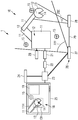
- Fig. 1 shows a schematic representation of an inventive device 1 for commissioning a multi-axis system 10.
- the multi-axis system 10 may be, for example, an industrial robot, a production or packaging machine, a CNC milling machine, a loading crane or the like.
- a multi-axis system is also to be understood as meaning a production cell with a plurality of such machines.
- the multi-axis system 10 comprises a number of segments 11, which are connected in pairs via a joint 12. At a free end of a last segment 11, a tool 13 with a TCP (Tool Center Point) 14 is arranged by way of example.
- TCP Tool Center Point
- the TCP is a reference point located at a suitable location on the tool 13.
- the kinematics of the multi-axis system 10 is controlled by a controller 20.
- the controller for example a programmable logic controller (PLC)
- PLC programmable logic controller
- the multi-axis system 10 includes functionally safe sensors (not shown) for detecting the axial positions of the kinematics, ie the individual segments 11 and joints 12.
- the values of the functionally safe sensors are provided by a functionally safe control (so-called F-PLC) on which a functionally safe program runs.
- F-PLC functionally safe control
- the functionally safe controller 21 also calculates the current position of the kinematics enveloping body in a so-called.
- World coordinate system It checks whether there is an overlap between later-described enveloping bodies and the protective spaces, or whether an enveloping body leaves the working space.
- the function of the functionally safe controller 21 is to monitor compliance with a maximum speed during manual multi-axis system operation that may be necessary to perform a method step during multi-system commissioning. If one of these cases occurs, a safety function is executed, eg stopping the kinematics.
- controller 20 and the functionally safe controller 21 are shown as separate components, the controller 20 and the functionally safe controller 21 may also be implemented by a single controller.
- the device comprises a programming device 22 which is connected to the controller and / or the functionally safe controller 21 in order to load a program or parameter into the controller 20 or functionally safe controller 21 and to read out values calculated therefrom.
- the device 1 further comprises a camera system 26.
- the camera system 26 comprises a first camera 27 which detects the environment of the multi-axis system 10. The image captured by the first camera 27 is used to determine the position of the camera system and the orientation of the camera system 26.
- the camera system 26 includes an optional second camera 28.
- the optional second camera 28 serves to provide a particular cutout (in this description also referred to as a scene). If the camera system also includes the optional second camera 28 in addition to the first camera 27, these are connected to one another by means of a rigid connection 29. As a result, the position and orientation of the first and the second camera 27, 28 are known to each other.
- the use of two cameras 27, 28 shown in this embodiment allows observation of the scene from different angles.
- a detection range of the first camera 27 is denoted by 27E and a detection range of the second camera 28 is indicated by 28E. It is readily apparent that the detection area 27E detects the multi-axis system 10 as a whole, while the detection area of the 28E of the second camera 28 is selected such that, in particular, the tool 13 and a part of the segment holding the tool 11 are detected.
- the use of a second camera also reduces the risk of obscuring portions of the multi-axis system 10.
- the device 1 further comprises an AR system 23, which reads in the image captured by the first camera 27 and determines the position of the first camera 27 or of the camera pair by evaluating the image information.
- the image of the second camera 28 and information from the functionally safe controller 21 are also read by the AR system, combined with each other and forwarded to an output device 25 for visualization.
- the AR system 23 may be implemented in software and executed on the programmer 22. Alternatively, the AR system 23 may be implemented as a standalone component as shown. In this case, there is a communication link to the programmer 22.
- an output device 25 which, in this embodiment, displays the image captured by the second camera 28.
- the output device 25 may be a computer, such as a PC, a laptop, a tablet, a smartphone, but also an AR glasses and any other device for displaying two-dimensional or three-dimensional images.
- various dispensers for example one during the definition of the enveloping bodies described in more detail below, and another during the test.
- the first and the second camera 27, 28, the output device 25 may be combined with the AR system 23 in a common device.
- markers 15 are distributed.
- the markers 15 can be optical markers, such as stickers, but also objects with a specific shape and / or color. However, in general, selected edges and / or corners or other significant components of the multi-axis system 10 and / or the environment of the multi-axis system can also be used as optical markers 15. It is useful if the markers 15 are arranged evenly in the room.
- the AR system 23 it is possible for the AR system 23 to make an exact position determination as well as a determination of the position and orientation of the camera system 26. If the AR system does not require markers for position determination, since other components and / or technical units are used for position determination, the markers 15 need not be optically detectable by the camera system 26.
- a first step several of the markers 15 are arranged at suitable locations, which enable the AR system 23 to locate the camera system 26 exactly.
- the locations of the placement of the markers 15 are selected such that the markers 15 can be detected from as many viewing angles as possible for the camera system 26.
- the position of the markers 15 in a global coordinate system of the kinematics of the multi-axis system 10 is determined. This is done e.g. in that the TCP 14 of the tool 13 is moved to a respective marker 15 and the position is confirmed by the input device 24.
- the Cartesian coordinates of the respective marker 15 can be reliably determined.
- the markers 15 are then determined in the global coordinate system of the multi-axis system 10.
- Moving the TCP to a respective marker 15 can be done manually, for example, in so-called jog mode. Similarly, moving the TCP to a particular marker can be done automatically. For this purpose, a mark is applied to the TCP 14 of the tool 12 so that the AR system 23 is enabled to calculate the distance of the TCP 14 to the respective markers 15. For a given marker 15, the segments 11 of the multi-axis system are moved as part of a search process until this distance becomes minimal. This procedure is repeated for all markers 15.
- a laser range meter with radio interface (not shown) to the TCP 14.
- the AR system 23 detects the laser spot in Camera image, eg by switching on / off a laser of the distance measuring device and observing the pixels in the camera image.
- the AR system 23 detects the marker 15 and calculates the distance between the laser spot and the marker 15 concerned.
- the AR system 23 wirelessly reads the measured distance from the range finder and combines it with the coordinates of the TCP from the controller 20 of the multi-axis system 10.
- the controller 20 then moves the kinematics of the multi-axis system 10 according to the calculated distance until the laser spot is superimposed on the marker 15.
- This process is carried out until all markers 15 in the coordinate system of the multi-axis system 10 have been measured.
- the positional coordinates of the markers 15 are transmitted from the functionally safe controller 21 to the AR system 23.
- the AR system 23 is thereby able to select from a moving image of the camera system 26 containing the markers 15. to close the position and direction of the camera system in the global coordinate system.
- the previously detected markers 15 are not sufficient to determine the position and direction of the camera system 26, for example because not all or not enough markers 15 are visible from all necessary viewing angles, further temporary markers can be arranged in the environment of the multi-axis system 10.
- the position of the temporary markers (not shown) can be determined by the AR system 23 with the aid of the previous markers 15.
- a calibration of the temporary markers is not required.
- existing reference points e.g. Corner points of immovable objects or the like can be used as temporary markers.
- the enveloping body is defined for the components (segments 11, joints 12, tool 13) of the multi-axis system 10.
- an enveloping body 11H, 13H may have the shape of a cuboid defined by a number of vertices. If the enveloping body is a sphere, then the sphere can be defined by at least three points on the sphere surface.
- a user holds the auxiliary marker to the desired position of a fulcrum and activates the input device. This causes the AR system 23 to calculate the position of the auxiliary marker. The calculation is based on the image data and the marker 15 contained in the image data whose position is known in the first, global coordinate system.
- the enveloping body 11H, 13H is calculated and stored in the functionally safe controller 21. This is repeated for all components of the multi-axis system 10.
- a respective enveloping body 11H, 13H assigned to a component 11, 13 surrounds the component in its entirety.
- an enveloping body can be defined, e.g. Cuboid, sphere or similar.
- the enveloping body is interactively placed over the input device and controlled by the output device by moving the auxiliary marker to the appropriate position and orientation. With the help of the input device 24, the correct position and orientation is confirmed. Subsequently, the dimension, position and orientation of the placed enveloping body can be adjusted in a similar manner until a desired accuracy is achieved.
- the enveloping bodies are divided into shelters, working spaces and enveloping bodies.
- the enveloping bodies are assigned to the individual components (segments 11, tool 13, joints 12) of the kinematics of the multi-axis system 10. It is understood that the protective or Workspaces may have been created in the course of defining the body or in advance.
- the checking of the defined enveloping bodies 11H, 13H takes place in that the functionally safe control 21 calculates the position of the enveloping body, possibly in dependence on current positions of the segments 11, 13 of the multi-axis system 10.
- the AR system 23 reads in the current position and orientation of the enveloping bodies 11H, 13H and the shelter 19 from the functionally safe controller 21. Subsequently, the AR system 23 transforms the enveloping bodies 11H, 13H and the guard space 19, respectively, according to the position and orientation of the camera system 26.
- the enveloping bodies 11H, 13H and the working space (s) 18 and the guard space (s) 19 are combined with the actual image of the camera system 26 overlaid and displayed on the output device 25.
- the working space is only indicated schematically by the reference numeral 18.
- the enveloping body 11H for the segment 11 and 13H for the tool 13 are each shown as a cuboid.
- a shelter 19 exemplified in the shape of a cuboid, is visualized.
- the respective components of the multi-axis system 10. With the help of the AR system can then be checked whether the previously defined and stored enveloping body, protective and working spaces with the Reality match.
- the camera system 26 can be moved to view the enveloping bodies 11H, 13H and the working space (s) 18, 19 from different angles of view.
- the AR system 23 can exactly locate the position and orientation of the camera system 26 even without marker 15, the positioning of the markers 15 and their calibration and transmission of the position coordinates to the AR system 23 can be dispensed with. This is possible, for example, if it is possible to locate the position and orientation of the camera system solely by analyzing the image of the camera system 26 or by using special sensors which are installed, for example, on or in the camera system 26.
- a step-by-step process may be defined, leading through the definition of envelopes. In this way, no component of the multi-axis system can be forgotten.
Landscapes
- Engineering & Computer Science (AREA)
- Physics & Mathematics (AREA)
- General Physics & Mathematics (AREA)
- Theoretical Computer Science (AREA)
- Computer Vision & Pattern Recognition (AREA)
- Robotics (AREA)
- Mechanical Engineering (AREA)
- Automation & Control Theory (AREA)
- Computer Graphics (AREA)
- Quality & Reliability (AREA)
- Multimedia (AREA)
- Computer Hardware Design (AREA)
- General Engineering & Computer Science (AREA)
- Software Systems (AREA)
- Manufacturing & Machinery (AREA)
- Human Computer Interaction (AREA)
- Manipulator (AREA)
- Length Measuring Devices By Optical Means (AREA)
Priority Applications (3)
| Application Number | Priority Date | Filing Date | Title |
|---|---|---|---|
| EP16199731.7A EP3323565B1 (fr) | 2016-11-21 | 2016-11-21 | Procédé et dispositif de mise en service d'un système multiaxial |
| US15/818,375 US10482589B2 (en) | 2016-11-21 | 2017-11-20 | Method and apparatus for the start-up operation of a multi-axis system |
| CN201711163401.9A CN108081267B (zh) | 2016-11-21 | 2017-11-20 | 用于启动多轴系统的方法和装置 |
Applications Claiming Priority (1)
| Application Number | Priority Date | Filing Date | Title |
|---|---|---|---|
| EP16199731.7A EP3323565B1 (fr) | 2016-11-21 | 2016-11-21 | Procédé et dispositif de mise en service d'un système multiaxial |
Publications (2)
| Publication Number | Publication Date |
|---|---|
| EP3323565A1 true EP3323565A1 (fr) | 2018-05-23 |
| EP3323565B1 EP3323565B1 (fr) | 2021-06-30 |
Family
ID=57396275
Family Applications (1)
| Application Number | Title | Priority Date | Filing Date |
|---|---|---|---|
| EP16199731.7A Active EP3323565B1 (fr) | 2016-11-21 | 2016-11-21 | Procédé et dispositif de mise en service d'un système multiaxial |
Country Status (3)
| Country | Link |
|---|---|
| US (1) | US10482589B2 (fr) |
| EP (1) | EP3323565B1 (fr) |
| CN (1) | CN108081267B (fr) |
Cited By (2)
| Publication number | Priority date | Publication date | Assignee | Title |
|---|---|---|---|---|
| US10424122B2 (en) | 2016-12-06 | 2019-09-24 | Fanuc Corporation | Augmented reality simulation device which displays a virtual object on a machine tool and computer-readable medium |
| US11660755B2 (en) | 2019-10-15 | 2023-05-30 | Siemens Aktiengesellschaft | Apparatus and method for monitoring a working environment |
Families Citing this family (3)
| Publication number | Priority date | Publication date | Assignee | Title |
|---|---|---|---|---|
| DE112019003204T5 (de) * | 2018-06-26 | 2021-03-11 | Fanuc America Corporation | Visualisierung und modifizierung von arbeitsrandbereichen unter verwendung von erweiterter realität |
| US12036663B2 (en) * | 2019-03-25 | 2024-07-16 | Abb Schweiz Ag | Method and control arrangement for determining a relation between a robot coordinate system and a movable apparatus coordinate system |
| EP4212287A1 (fr) | 2022-01-18 | 2023-07-19 | Siemens Aktiengesellschaft | Planification d'une surveillance de sécurité pour une cinématique à axes multiples comprenant plusieurs segments mobiles |
Citations (4)
| Publication number | Priority date | Publication date | Assignee | Title |
|---|---|---|---|---|
| DE10226140A1 (de) * | 2002-06-13 | 2004-01-08 | Kuka Roboter Gmbh | Verfahren und Vorrichtung zum Vermeiden von Kollisionen zwischen Industrierobotern und anderen Objekten |
| EP2230054A1 (fr) * | 2007-12-07 | 2010-09-22 | Kabushiki Kaisha Yaskawa Denki | Procédé de régulation de mouvement de robot, système de robot et dispositif de régulation de mouvement de robot |
| EP2783812A2 (fr) * | 2013-03-18 | 2014-10-01 | Kabushiki Kaisha Yaskawa Denki | Dispositif de robot et procédé de fabrication d'un objet |
| DE112014000700T5 (de) * | 2013-02-06 | 2015-10-22 | Mitsubishi Electric Corporation | Interferenzprüfgerät |
Family Cites Families (7)
| Publication number | Priority date | Publication date | Assignee | Title |
|---|---|---|---|---|
| DE10323217A1 (de) * | 2003-05-22 | 2004-12-16 | Siemens Ag | Optisches Kohärenztomographiesystem zur Untersuchung des menschlichen oder tierischen Gewebes oder von Organen |
| CN107510506A (zh) * | 2009-03-24 | 2017-12-26 | 伊顿株式会社 | 利用增强现实技术的手术机器人系统及其控制方法 |
| JP5523386B2 (ja) * | 2011-04-15 | 2014-06-18 | 三菱電機株式会社 | 衝突回避装置 |
| WO2014036034A1 (fr) * | 2012-08-27 | 2014-03-06 | University Of Houston | Dispositif robotique, logiciel, matériel système associés et leurs procédés d'utilisation en chirurgie guidée par l'image et assistée par robot |
| US9336629B2 (en) * | 2013-01-30 | 2016-05-10 | F3 & Associates, Inc. | Coordinate geometry augmented reality process |
| EP3104276A1 (fr) | 2015-06-09 | 2016-12-14 | Siemens Aktiengesellschaft | Procede dans un systeme informatique, programme informatique et installation de traitement de donnees |
| CN104942809B (zh) * | 2015-06-23 | 2018-04-17 | 广东工业大学 | 基于视觉伺服系统的机械臂动态模糊逼近器 |
-
2016
- 2016-11-21 EP EP16199731.7A patent/EP3323565B1/fr active Active
-
2017
- 2017-11-20 CN CN201711163401.9A patent/CN108081267B/zh active Active
- 2017-11-20 US US15/818,375 patent/US10482589B2/en active Active
Patent Citations (4)
| Publication number | Priority date | Publication date | Assignee | Title |
|---|---|---|---|---|
| DE10226140A1 (de) * | 2002-06-13 | 2004-01-08 | Kuka Roboter Gmbh | Verfahren und Vorrichtung zum Vermeiden von Kollisionen zwischen Industrierobotern und anderen Objekten |
| EP2230054A1 (fr) * | 2007-12-07 | 2010-09-22 | Kabushiki Kaisha Yaskawa Denki | Procédé de régulation de mouvement de robot, système de robot et dispositif de régulation de mouvement de robot |
| DE112014000700T5 (de) * | 2013-02-06 | 2015-10-22 | Mitsubishi Electric Corporation | Interferenzprüfgerät |
| EP2783812A2 (fr) * | 2013-03-18 | 2014-10-01 | Kabushiki Kaisha Yaskawa Denki | Dispositif de robot et procédé de fabrication d'un objet |
Cited By (2)
| Publication number | Priority date | Publication date | Assignee | Title |
|---|---|---|---|---|
| US10424122B2 (en) | 2016-12-06 | 2019-09-24 | Fanuc Corporation | Augmented reality simulation device which displays a virtual object on a machine tool and computer-readable medium |
| US11660755B2 (en) | 2019-10-15 | 2023-05-30 | Siemens Aktiengesellschaft | Apparatus and method for monitoring a working environment |
Also Published As
| Publication number | Publication date |
|---|---|
| US20180144459A1 (en) | 2018-05-24 |
| EP3323565B1 (fr) | 2021-06-30 |
| US10482589B2 (en) | 2019-11-19 |
| CN108081267B (zh) | 2021-03-09 |
| CN108081267A (zh) | 2018-05-29 |
Similar Documents
| Publication | Publication Date | Title |
|---|---|---|
| EP3324362B1 (fr) | Procédé et dispositif de mise en service d'un système multiaxes | |
| DE102010023736B4 (de) | Robotersystem mit Problemerkennungsfunktion | |
| DE102018009023B4 (de) | Einlernvorrichtung zum Ausführen von Robotereinlernvorgängen und Einlernverfahren | |
| EP3323565B1 (fr) | Procédé et dispositif de mise en service d'un système multiaxial | |
| EP1521211B1 (fr) | Procédé et processus pour déterminer la position et l'orientation d'un récepteur d'images | |
| EP3030359B1 (fr) | Presse à plier | |
| DE102013114372A1 (de) | Laststand-anzeige für eine werkzeugmaschine | |
| DE102017002603A1 (de) | Robotersystem, das Roboter umfassend mehrere mechanische Einheiten steuert, mechanische Einheiten und Robotersteuervorrichtung | |
| DE102017222057B4 (de) | Robotersystem | |
| EP2500148B1 (fr) | Procédé et dispositif de commande d'un robot avec un modèle virtuel du robot | |
| DE102019212452A1 (de) | Interferenzvermeidungsvorrichtung und Robotersystem | |
| WO2019096479A1 (fr) | Procédé et moyen pour faire fonctionner un système robotique | |
| DE102016203701A1 (de) | Industrieroboter mit mindestens zwei Bilderfassungseinrichtungen | |
| DE102013017007A1 (de) | Roboter mit einem Endmanipulatorarm mit Endeffektor sowie Verfahren zur Bestimmung eines Kraft- und Drehmomenteintrages auf einen Endeffektor eines Roboters | |
| EP3974936A1 (fr) | Configuration d'un dispositif de visualisation pour une zone de machine | |
| DE102017213658A1 (de) | Handhabungsanordnung mit einer Handhabungseinrichtung zur Durchführung mindestens eines Arbeitsschritts sowie Verfahren und Computerprogramm | |
| WO2017067626A1 (fr) | Vérification de la position d'un système de manipulation | |
| DE112021004660T5 (de) | Robotersystem | |
| DE102010047641A1 (de) | Steuerung eines Roboters | |
| DE4015644A1 (de) | Verfahren zum bestimmen relevanter punkte eines werkzeugs am handflansch eines gesteuerten mehrachsigen manipulators | |
| DE112021001048T5 (de) | Steuervorrichtung und steuerverfahren für einen roboter, robotersystem sowie vorrichtung und verfahren zum erzeugen eines betriebsprogramms eines roboters | |
| EP2703920B1 (fr) | Procédé d'apprentissage de la commande d'une machine | |
| DE102006005990B4 (de) | Werkstückvermessung für 3-D Lageerkennung in mehreren Multi-Roboter-Stationen | |
| DE102015200319A1 (de) | Einmessverfahren aus Kombination von Vorpositionierung und Handführen | |
| EP1471401A2 (fr) | Procédé pour mesurer le système de coordonnées d'une camera robot par rapport au système de coordonnées du robot ou vice versa |
Legal Events
| Date | Code | Title | Description |
|---|---|---|---|
| PUAI | Public reference made under article 153(3) epc to a published international application that has entered the european phase |
Free format text: ORIGINAL CODE: 0009012 |
|
| STAA | Information on the status of an ep patent application or granted ep patent |
Free format text: STATUS: THE APPLICATION HAS BEEN PUBLISHED |
|
| AK | Designated contracting states |
Kind code of ref document: A1 Designated state(s): AL AT BE BG CH CY CZ DE DK EE ES FI FR GB GR HR HU IE IS IT LI LT LU LV MC MK MT NL NO PL PT RO RS SE SI SK SM TR |
|
| AX | Request for extension of the european patent |
Extension state: BA ME |
|
| STAA | Information on the status of an ep patent application or granted ep patent |
Free format text: STATUS: REQUEST FOR EXAMINATION WAS MADE |
|
| 17P | Request for examination filed |
Effective date: 20180717 |
|
| RBV | Designated contracting states (corrected) |
Designated state(s): AL AT BE BG CH CY CZ DE DK EE ES FI FR GB GR HR HU IE IS IT LI LT LU LV MC MK MT NL NO PL PT RO RS SE SI SK SM TR |
|
| STAA | Information on the status of an ep patent application or granted ep patent |
Free format text: STATUS: EXAMINATION IS IN PROGRESS |
|
| 17Q | First examination report despatched |
Effective date: 20200617 |
|
| GRAP | Despatch of communication of intention to grant a patent |
Free format text: ORIGINAL CODE: EPIDOSNIGR1 |
|
| STAA | Information on the status of an ep patent application or granted ep patent |
Free format text: STATUS: GRANT OF PATENT IS INTENDED |
|
| INTG | Intention to grant announced |
Effective date: 20210222 |
|
| GRAS | Grant fee paid |
Free format text: ORIGINAL CODE: EPIDOSNIGR3 |
|
| GRAA | (expected) grant |
Free format text: ORIGINAL CODE: 0009210 |
|
| STAA | Information on the status of an ep patent application or granted ep patent |
Free format text: STATUS: THE PATENT HAS BEEN GRANTED |
|
| AK | Designated contracting states |
Kind code of ref document: B1 Designated state(s): AL AT BE BG CH CY CZ DE DK EE ES FI FR GB GR HR HU IE IS IT LI LT LU LV MC MK MT NL NO PL PT RO RS SE SI SK SM TR |
|
| REG | Reference to a national code |
Ref country code: CH Ref legal event code: EP |
|
| REG | Reference to a national code |
Ref country code: AT Ref legal event code: REF Ref document number: 1405917 Country of ref document: AT Kind code of ref document: T Effective date: 20210715 |
|
| REG | Reference to a national code |
Ref country code: DE Ref legal event code: R096 Ref document number: 502016013304 Country of ref document: DE |
|
| REG | Reference to a national code |
Ref country code: IE Ref legal event code: FG4D Free format text: LANGUAGE OF EP DOCUMENT: GERMAN |
|
| REG | Reference to a national code |
Ref country code: LT Ref legal event code: MG9D |
|
| PG25 | Lapsed in a contracting state [announced via postgrant information from national office to epo] |
Ref country code: FI Free format text: LAPSE BECAUSE OF FAILURE TO SUBMIT A TRANSLATION OF THE DESCRIPTION OR TO PAY THE FEE WITHIN THE PRESCRIBED TIME-LIMIT Effective date: 20210630 Ref country code: HR Free format text: LAPSE BECAUSE OF FAILURE TO SUBMIT A TRANSLATION OF THE DESCRIPTION OR TO PAY THE FEE WITHIN THE PRESCRIBED TIME-LIMIT Effective date: 20210630 Ref country code: BG Free format text: LAPSE BECAUSE OF FAILURE TO SUBMIT A TRANSLATION OF THE DESCRIPTION OR TO PAY THE FEE WITHIN THE PRESCRIBED TIME-LIMIT Effective date: 20210930 |
|
| REG | Reference to a national code |
Ref country code: NL Ref legal event code: MP Effective date: 20210630 |
|
| PG25 | Lapsed in a contracting state [announced via postgrant information from national office to epo] |
Ref country code: RS Free format text: LAPSE BECAUSE OF FAILURE TO SUBMIT A TRANSLATION OF THE DESCRIPTION OR TO PAY THE FEE WITHIN THE PRESCRIBED TIME-LIMIT Effective date: 20210630 Ref country code: SE Free format text: LAPSE BECAUSE OF FAILURE TO SUBMIT A TRANSLATION OF THE DESCRIPTION OR TO PAY THE FEE WITHIN THE PRESCRIBED TIME-LIMIT Effective date: 20210630 Ref country code: NO Free format text: LAPSE BECAUSE OF FAILURE TO SUBMIT A TRANSLATION OF THE DESCRIPTION OR TO PAY THE FEE WITHIN THE PRESCRIBED TIME-LIMIT Effective date: 20210930 Ref country code: LV Free format text: LAPSE BECAUSE OF FAILURE TO SUBMIT A TRANSLATION OF THE DESCRIPTION OR TO PAY THE FEE WITHIN THE PRESCRIBED TIME-LIMIT Effective date: 20210630 Ref country code: GR Free format text: LAPSE BECAUSE OF FAILURE TO SUBMIT A TRANSLATION OF THE DESCRIPTION OR TO PAY THE FEE WITHIN THE PRESCRIBED TIME-LIMIT Effective date: 20211001 |
|
| PG25 | Lapsed in a contracting state [announced via postgrant information from national office to epo] |
Ref country code: SM Free format text: LAPSE BECAUSE OF FAILURE TO SUBMIT A TRANSLATION OF THE DESCRIPTION OR TO PAY THE FEE WITHIN THE PRESCRIBED TIME-LIMIT Effective date: 20210630 Ref country code: SK Free format text: LAPSE BECAUSE OF FAILURE TO SUBMIT A TRANSLATION OF THE DESCRIPTION OR TO PAY THE FEE WITHIN THE PRESCRIBED TIME-LIMIT Effective date: 20210630 Ref country code: CZ Free format text: LAPSE BECAUSE OF FAILURE TO SUBMIT A TRANSLATION OF THE DESCRIPTION OR TO PAY THE FEE WITHIN THE PRESCRIBED TIME-LIMIT Effective date: 20210630 Ref country code: EE Free format text: LAPSE BECAUSE OF FAILURE TO SUBMIT A TRANSLATION OF THE DESCRIPTION OR TO PAY THE FEE WITHIN THE PRESCRIBED TIME-LIMIT Effective date: 20210630 Ref country code: NL Free format text: LAPSE BECAUSE OF FAILURE TO SUBMIT A TRANSLATION OF THE DESCRIPTION OR TO PAY THE FEE WITHIN THE PRESCRIBED TIME-LIMIT Effective date: 20210630 Ref country code: PT Free format text: LAPSE BECAUSE OF FAILURE TO SUBMIT A TRANSLATION OF THE DESCRIPTION OR TO PAY THE FEE WITHIN THE PRESCRIBED TIME-LIMIT Effective date: 20211102 Ref country code: RO Free format text: LAPSE BECAUSE OF FAILURE TO SUBMIT A TRANSLATION OF THE DESCRIPTION OR TO PAY THE FEE WITHIN THE PRESCRIBED TIME-LIMIT Effective date: 20210630 Ref country code: ES Free format text: LAPSE BECAUSE OF FAILURE TO SUBMIT A TRANSLATION OF THE DESCRIPTION OR TO PAY THE FEE WITHIN THE PRESCRIBED TIME-LIMIT Effective date: 20210630 |
|
| PG25 | Lapsed in a contracting state [announced via postgrant information from national office to epo] |
Ref country code: PL Free format text: LAPSE BECAUSE OF FAILURE TO SUBMIT A TRANSLATION OF THE DESCRIPTION OR TO PAY THE FEE WITHIN THE PRESCRIBED TIME-LIMIT Effective date: 20210630 |
|
| REG | Reference to a national code |
Ref country code: DE Ref legal event code: R097 Ref document number: 502016013304 Country of ref document: DE |
|
| PG25 | Lapsed in a contracting state [announced via postgrant information from national office to epo] |
Ref country code: DK Free format text: LAPSE BECAUSE OF FAILURE TO SUBMIT A TRANSLATION OF THE DESCRIPTION OR TO PAY THE FEE WITHIN THE PRESCRIBED TIME-LIMIT Effective date: 20210630 |
|
| PLBE | No opposition filed within time limit |
Free format text: ORIGINAL CODE: 0009261 |
|
| STAA | Information on the status of an ep patent application or granted ep patent |
Free format text: STATUS: NO OPPOSITION FILED WITHIN TIME LIMIT |
|
| PG25 | Lapsed in a contracting state [announced via postgrant information from national office to epo] |
Ref country code: AL Free format text: LAPSE BECAUSE OF FAILURE TO SUBMIT A TRANSLATION OF THE DESCRIPTION OR TO PAY THE FEE WITHIN THE PRESCRIBED TIME-LIMIT Effective date: 20210630 |
|
| 26N | No opposition filed |
Effective date: 20220331 |
|
| PG25 | Lapsed in a contracting state [announced via postgrant information from national office to epo] |
Ref country code: MC Free format text: LAPSE BECAUSE OF FAILURE TO SUBMIT A TRANSLATION OF THE DESCRIPTION OR TO PAY THE FEE WITHIN THE PRESCRIBED TIME-LIMIT Effective date: 20210630 |
|
| REG | Reference to a national code |
Ref country code: CH Ref legal event code: PL |
|
| GBPC | Gb: european patent ceased through non-payment of renewal fee |
Effective date: 20211121 |
|
| PG25 | Lapsed in a contracting state [announced via postgrant information from national office to epo] |
Ref country code: LU Free format text: LAPSE BECAUSE OF NON-PAYMENT OF DUE FEES Effective date: 20211121 Ref country code: BE Free format text: LAPSE BECAUSE OF NON-PAYMENT OF DUE FEES Effective date: 20211130 |
|
| REG | Reference to a national code |
Ref country code: BE Ref legal event code: MM Effective date: 20211130 |
|
| PG25 | Lapsed in a contracting state [announced via postgrant information from national office to epo] |
Ref country code: IE Free format text: LAPSE BECAUSE OF NON-PAYMENT OF DUE FEES Effective date: 20211121 Ref country code: GB Free format text: LAPSE BECAUSE OF NON-PAYMENT OF DUE FEES Effective date: 20211121 |
|
| REG | Reference to a national code |
Ref country code: AT Ref legal event code: MM01 Ref document number: 1405917 Country of ref document: AT Kind code of ref document: T Effective date: 20211121 |
|
| PG25 | Lapsed in a contracting state [announced via postgrant information from national office to epo] |
Ref country code: AT Free format text: LAPSE BECAUSE OF NON-PAYMENT OF DUE FEES Effective date: 20211121 |
|
| PG25 | Lapsed in a contracting state [announced via postgrant information from national office to epo] |
Ref country code: LT Free format text: LAPSE BECAUSE OF FAILURE TO SUBMIT A TRANSLATION OF THE DESCRIPTION OR TO PAY THE FEE WITHIN THE PRESCRIBED TIME-LIMIT Effective date: 20210630 |
|
| PG25 | Lapsed in a contracting state [announced via postgrant information from national office to epo] |
Ref country code: HU Free format text: LAPSE BECAUSE OF FAILURE TO SUBMIT A TRANSLATION OF THE DESCRIPTION OR TO PAY THE FEE WITHIN THE PRESCRIBED TIME-LIMIT; INVALID AB INITIO Effective date: 20161121 |
|
| PG25 | Lapsed in a contracting state [announced via postgrant information from national office to epo] |
Ref country code: CY Free format text: LAPSE BECAUSE OF FAILURE TO SUBMIT A TRANSLATION OF THE DESCRIPTION OR TO PAY THE FEE WITHIN THE PRESCRIBED TIME-LIMIT Effective date: 20210630 |
|
| PG25 | Lapsed in a contracting state [announced via postgrant information from national office to epo] |
Ref country code: LI Free format text: LAPSE BECAUSE OF NON-PAYMENT OF DUE FEES Effective date: 20220630 Ref country code: CH Free format text: LAPSE BECAUSE OF NON-PAYMENT OF DUE FEES Effective date: 20220630 |
|
| PG25 | Lapsed in a contracting state [announced via postgrant information from national office to epo] |
Ref country code: MK Free format text: LAPSE BECAUSE OF FAILURE TO SUBMIT A TRANSLATION OF THE DESCRIPTION OR TO PAY THE FEE WITHIN THE PRESCRIBED TIME-LIMIT Effective date: 20210630 |
|
| PG25 | Lapsed in a contracting state [announced via postgrant information from national office to epo] |
Ref country code: TR Free format text: LAPSE BECAUSE OF FAILURE TO SUBMIT A TRANSLATION OF THE DESCRIPTION OR TO PAY THE FEE WITHIN THE PRESCRIBED TIME-LIMIT Effective date: 20210630 |
|
| PG25 | Lapsed in a contracting state [announced via postgrant information from national office to epo] |
Ref country code: MT Free format text: LAPSE BECAUSE OF FAILURE TO SUBMIT A TRANSLATION OF THE DESCRIPTION OR TO PAY THE FEE WITHIN THE PRESCRIBED TIME-LIMIT Effective date: 20210630 |
|
| PGFP | Annual fee paid to national office [announced via postgrant information from national office to epo] |
Ref country code: IT Payment date: 20251125 Year of fee payment: 10 |
|
| PGFP | Annual fee paid to national office [announced via postgrant information from national office to epo] |
Ref country code: FR Payment date: 20251114 Year of fee payment: 10 |
|
| PGFP | Annual fee paid to national office [announced via postgrant information from national office to epo] |
Ref country code: DE Payment date: 20260119 Year of fee payment: 10 |