EP3323675A1 - Système de fixation pour ceintures de retenue - Google Patents
Système de fixation pour ceintures de retenue Download PDFInfo
- Publication number
- EP3323675A1 EP3323675A1 EP17001842.8A EP17001842A EP3323675A1 EP 3323675 A1 EP3323675 A1 EP 3323675A1 EP 17001842 A EP17001842 A EP 17001842A EP 3323675 A1 EP3323675 A1 EP 3323675A1
- Authority
- EP
- European Patent Office
- Prior art keywords
- platform
- opening
- belt
- face
- fastening
- Prior art date
- Legal status (The legal status is an assumption and is not a legal conclusion. Google has not performed a legal analysis and makes no representation as to the accuracy of the status listed.)
- Granted
Links
- 230000003014 reinforcing effect Effects 0.000 claims description 9
- 230000005540 biological transmission Effects 0.000 claims description 8
- 238000009434 installation Methods 0.000 description 2
- 230000001133 acceleration Effects 0.000 description 1
- 230000015572 biosynthetic process Effects 0.000 description 1
- 230000001419 dependent effect Effects 0.000 description 1
- 238000003780 insertion Methods 0.000 description 1
- 230000037431 insertion Effects 0.000 description 1
- 238000004519 manufacturing process Methods 0.000 description 1
- 239000000203 mixture Substances 0.000 description 1
- 238000012986 modification Methods 0.000 description 1
- 230000004048 modification Effects 0.000 description 1
- 230000036316 preload Effects 0.000 description 1
- 239000000725 suspension Substances 0.000 description 1
- 230000002747 voluntary effect Effects 0.000 description 1
Images






Classifications
-
- B—PERFORMING OPERATIONS; TRANSPORTING
- B60—VEHICLES IN GENERAL
- B60P—VEHICLES ADAPTED FOR LOAD TRANSPORTATION OR TO TRANSPORT, TO CARRY, OR TO COMPRISE SPECIAL LOADS OR OBJECTS
- B60P3/00—Vehicles adapted to transport, to carry or to comprise special loads or objects
- B60P3/06—Vehicles adapted to transport, to carry or to comprise special loads or objects for carrying vehicles
- B60P3/07—Vehicles adapted to transport, to carry or to comprise special loads or objects for carrying vehicles for carrying road vehicles
- B60P3/073—Vehicle retainers
- B60P3/075—Vehicle retainers for wheels, hubs, or axle shafts
-
- B—PERFORMING OPERATIONS; TRANSPORTING
- B60—VEHICLES IN GENERAL
- B60P—VEHICLES ADAPTED FOR LOAD TRANSPORTATION OR TO TRANSPORT, TO CARRY, OR TO COMPRISE SPECIAL LOADS OR OBJECTS
- B60P7/00—Securing or covering of load on vehicles
- B60P7/06—Securing of load
- B60P7/08—Securing to the vehicle floor or sides
- B60P7/0807—Attachment points
Definitions
- the present invention refers to a fastening system for holding belts aimed in particular to be used for transporting motor vehicles on loading platforms.
- object of the present invention is solving the above prior art problems, by providing a fastening system for holding belts, aimed in particular to be used for transporting motor vehicles on loading platforms, which allows minimizing the tension concentrations exerted by the belts on the platform itself and reduce, if not remove, the formation of permanent deformations next to the contact area of the oval holes of the loading platform.
- an object of the present invention is providing a fastening system for holding belts which is dedicated to each (usually three) of the different fastening points of the belts on the oval holes of the loading platform.
- Another object of the present invention is providing a fastening system which can be correctly customized depending on the specific fastening point to which it must be applied in terms of direction along which the system itself applies the force to the loading platform and, therefore, for the different contact area between oval hole and fastening system.
- the fastening system for holding belts according to the present invention comprises at least one interposing element 1A, 1B, 1C arranged between a belt 3 and a platform 5, the interposing element 1A, 1B, 1C being equipped with cooperating means with the platform 5 adapted to minimize the tension concentrations induced by a force exerted by the belt 3 on the platform 5.
- the fastening system according to the present invention could comprise at least one first interposing element 1A composed of at least one first fastening element of at least one first terminal portion of the belt 3, typically by interposing at least one tensioning device 7, such as, for example, a ratchet of the type known in the art.
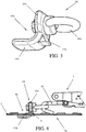
- the cooperating means are composed of at least one supporting body 11A adapted to be partially inserted through at least one opening 9 of the platform 5 (the opening 9 being, for example, a through oval hole of the platform 5), the supporting body 11A comprising at least one engaging portion 13A adapted to go out from a first face 5a of the platform 5 (for example through the oval hole) and at least one fastening portion 15A for connecting the belt adapted to go out from a second face 5b of the platform 5 (preferably always through the oval hole), the second face 5b being opposite to the first face 5a.
- the engaging portion 13A has a substantially flat shape with rounded edges.
- the supporting body 11A could have, seen laterally, a shape substantially as an "L" in which the engaging portion 13A is inclined with respect to the fastening portion 15A by an angle ⁇ included between 80° and 100°.
- the engaging portion 13A can be equipped with at least one projection 17A adapted to prevent that the engaging portion 13A can be accidentally withdrawn from the opening 9 of the platform 5.
- the fastening portion 15A can be equipped with at least one hook or eyelet 19A, preferably of the rotating type, aimed to allow the connection of the terminal portion of the belt or of the tensioning device 7, for example by interposing at least one hook 11 or other similar connecting means: in particular, the hook or eyelet 19A can have a rounded shape and mechanical characteristics suitable for well supporting the tension exerted by the belt; moreover, the hook or eyelet 19A, being rotatable, can offer a good fastening point for the hook 11 of the belt and can be suited at different angles.
- the engaging portion 13A advantageously allows distributing the pressure exerted by the traction of the belt on the majority of the edge of the opening 9, and in particular of the oval hole, in order to drastically reduce the specific pressure and avoid flexion phenomena of the sheet composing the platform 5.
- the possible projection 17A opposes the accidental disengagement of the first interposing element 1A since the belt traction force tends to fit more and more in the engaging portion 13A, preventing it from coming out and requiring an accurate manoeuvre to free it from the opening 9 of the platform 5.
- the fastening system according to the present invention could comprise at least one second interposing element 1B comprising at least one transmission element 11B of at least one intermediate portion of the belt.
- the belt applies a force which is the resultant of the two components, the one tangential to the platform 5, deriving from the portion of the belt 3a, and the one substantially perpendicular to the platform 5 itself deriving from the portion of the belt 3b, usually aimed to be wound around a tire 13: the vector composition of the two components thereby determines a force which has a direction with an angle approximately at 45° with respect to the sheet platform 5 and a greater intensity.
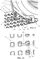
- the cooperating means are composed of at least one reinforcing plate 17B equipped with one or more through openings 19B, the plate 17B being adapted to abut on the surface on the platform 5 so that at least one through opening 19B is at least partially next to at least one of the openings 9 (oval hole) of the platform 5 itself.
- the transmission element 11B is then composed of a supporting body adapted to be partially inserted through at least one opening 9 of the platform 5 and at least one through opening 19B of the reinforcing plate 17B corresponding therewith, the supporting body comprising at least one transmission portion 21B of the belt adapted to go out from the second face 5b of the platform 5 (for example through the oval hole) and at least one fastening portion 23A of the transmission element 11B to the openings 9, 19B adapted to go out from the first face 5a of the platform 5 (preferably always through the oval hole and the through opening 19B of the reinforcing plate 17B).
- the shape of the through opening 19B of the reinforcing plate 17B can therefore be optimized, with respect to the possibly oval shape of the opening 9 of the platform 5, to receive the fastening portion 23A and the additional thickness offered by the reinforcing plate 17B itself, which contributes to stiffen and reinforce the sheet composing the platform 5.
- the second interposing element 1B further comprises at least one wheel-stopping wedge 13B which, as known, is generally a device normally used coupled with the belts to fasten the vehicles to the loading platforms and, for such purpose, comprising at least one stop abutment 15B against which, usually, the tire 13 is rested: advantageously, the wheel-stopping wedge 13B of the second interposing element 1B comprises at least one reinforcing plate 17B.
- wheel-stopping wedge 13B of the second interposing element 1B comprises at least one reinforcing plate 17B.
- the fastening system according to the present invention could comprise at least one third interposing element 1C composed of at least one second fastening element of at least one second terminal portion of the belt 3, typically by interposing at least one connecting device 15 such as, for example, a hook of a type known in the art.
- the belt 3 applies an almost perpendicular force to the platform 5: the contact with the connecting device 15 is therefore very critical and determines out-of-plane flexural forces and high localized contact pressure.
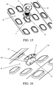
- the cooperating means are composed of at least one central pin 3C adapted to be inserted at least partially through at least one opening 9 of the platform 5 (the opening 9 being, for example, a through oval hole of the platform 5), the central pin 3C having a first end adapted to go out from the second face 5b of the platform 5 (for example through the oval hole) and a second end opposite to the first end adapted to go out from the first face 5a of the platform 5 (preferably always through the oval hole), the first end being equipped with at least one fastening portion 5C for connecting the belt (for example by interposing the connecting device 15) and the second end being equipped with at least one locking/unlocking device 7C adapted to allow, when taken in its operating unlocking position, the passage of at least the second end through the opening 9 of the platform 5 and to prevent, when taken in its operating locking position, the passage of at least the second end through the opening 9 of the platform 5.
- the cooperating means of the third interposing element 1C further comprise at least one abutment element 9C having bigger sizes with respect to the opening 9 of the platform 5 (therefore not passing through the opening 9) and axially sliding along the central pin 3C and at least one elastic means 11C (such as, for example, at least one helical spring) interposed between the abutment element 9C and the fastening portion 5C along the central pin 3C itself.
- at least one abutment element 9C having bigger sizes with respect to the opening 9 of the platform 5 (therefore not passing through the opening 9) and axially sliding along the central pin 3C and at least one elastic means 11C (such as, for example, at least one helical spring) interposed between the abutment element 9C and the fastening portion 5C along the central pin 3C itself.
- the abutment element 9C can be equipped with one or more projections 13C adapted to allow the element 9C itself to abut onto the plane surface surrounding the oval hole, avoiding mechanical interferences with the deep drawn projection of the oval hole itself.
- the fastening portion 5C can be equipped with at least one hook or eyelet, preferably integral with the pin 3C, aimed to allow the connection of the end portion of the belt 3 or of the connecting device 15.
- the locking/unlocking device 7C can be made as at least one pawl rotating around a central axis of the central pin 3C between the operating unlocking position in which the passage of the second end of the central pin 3C through the opening 9 is allows, and the operating locking position in which the passage of the second end of the central pin 3C through the opening 9 is prevented, and vice versa.
- the pawl and the fastening portion 5C are integral in rotation with the central pin 3C: consequently, by rotating the fastening portion 5C, it is possible to take in rotation the pawl between its operating positions through the opening 9, above all when the first face 5a of the platform 5 is easily accessed by the hands of an operator.
- the pawl can be equipped with one or more suitable planes 15C shaped in order to be coupled with the perimeter portion of the opening 9 of the first face 5a of the platform 5 against which it is aimed to abut.
- FIG. 15 With reference then to Figures 15 to 18 , some installation steps are shown for the third interposing element 1C of the fastening system according to the present invention inside an opening 9 (oval hole) of a loading platform 5.
- the abutment element 9C abuts onto the platform 5, and in particular onto the surface surrounding the opening 9 itself through the projections 13C.
- the third interposing element 1C by being inserted between the connecting device 15 and the sheet of the platform 5, consequently allows obtaining a force distributed on a wide area, strongly reducing the above tensions.
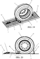
- Figures 19 and 20 show, as an example, the fastening system according to the present invention applied to a preferred use mode in which the system itself simultaneously comprises all three above described interposing elements 1A, 1B and 1C.
- one or more belts are traditionally used, one or more of the belts being aimed to be wound around the vehicle tire tread, to be then fastened and tensioned by suitable hooks or gaffs and ratchets in the openings (oval holes) of the platform.
- Figures 19 and 20 then show the fastening system according to the present invention in which the belt 3 is, in its second terminal portion, connected to the third interposing element 1C, partially wound around the tire 13, transmitted by the second interposing element 1B and finally connected, in its first terminal portion, to the first interposing element 1A where it is pun under traction through the tensioning device 7, allowing, next to each interposing element 1A, 1B and 1C, to minimize the tension concentrations induced by the force exerted by the belt 3 on the platform 5.
Landscapes
- Engineering & Computer Science (AREA)
- Transportation (AREA)
- Mechanical Engineering (AREA)
- Health & Medical Sciences (AREA)
- Public Health (AREA)
- Clamps And Clips (AREA)
- Basic Packing Technique (AREA)
Applications Claiming Priority (1)
| Application Number | Priority Date | Filing Date | Title |
|---|---|---|---|
| IT102016000116512A IT201600116512A1 (it) | 2016-11-18 | 2016-11-18 | Sistema di ancoraggio per cinghie di ritenuta. |
Publications (2)
| Publication Number | Publication Date |
|---|---|
| EP3323675A1 true EP3323675A1 (fr) | 2018-05-23 |
| EP3323675B1 EP3323675B1 (fr) | 2019-05-01 |
Family
ID=58266105
Family Applications (1)
| Application Number | Title | Priority Date | Filing Date |
|---|---|---|---|
| EP17001842.8A Active EP3323675B1 (fr) | 2016-11-18 | 2017-11-09 | Système de fixation pour ceintures de retenue |
Country Status (4)
| Country | Link |
|---|---|
| EP (1) | EP3323675B1 (fr) |
| IT (1) | IT201600116512A1 (fr) |
| LT (1) | LT3323675T (fr) |
| TR (1) | TR201907811T4 (fr) |
Cited By (2)
| Publication number | Priority date | Publication date | Assignee | Title |
|---|---|---|---|---|
| EP3636489A1 (fr) * | 2018-10-04 | 2020-04-15 | Moetefindt Fahrzeugbau GmbH & Co. KG | Crochet de sangle pour une tôle de fond à ouvertures et dispositif de fixation et sangle de serrage dotée de crochets de sangle |
| WO2020123064A1 (fr) * | 2018-12-11 | 2020-06-18 | Illinois Tool Works Inc. | Dispositif de fixation pour véhicules |
Citations (7)
| Publication number | Priority date | Publication date | Assignee | Title |
|---|---|---|---|---|
| US2591986A (en) * | 1951-02-23 | 1952-04-08 | Weiss Harry | One-piece tie down device and grabhook |
| DE19514811A1 (de) * | 1995-04-21 | 1996-10-24 | Hermann Schneebichler | Vorrichtung zur Befestigung von Personenkraftwagen auf Autotransport-Fahrzeugen |
| DE29724160U1 (de) * | 1997-03-26 | 2000-03-30 | Helmut Kuhnwaldt Spedition KG, 21109 Hamburg | Zurrgurt |
| US6328511B1 (en) * | 2000-02-07 | 2001-12-11 | Kinedyne Corporation | Vehicle transport restraint anchor |
| US20070212185A1 (en) * | 2005-08-12 | 2007-09-13 | Holland L.P. | "B" Hook Retainer for Railcar Anchor and Load Snugger Arrangement for Securing Cargo |
| EP2705983A2 (fr) * | 2012-09-06 | 2014-03-12 | Burg Silvergreen GmbH | Dispositif de sécurisation de marchandises |
| US20160031359A1 (en) * | 2013-03-28 | 2016-02-04 | Cordstrap B.V. | Method and system for securing heavy loads |
-
2016
- 2016-11-18 IT IT102016000116512A patent/IT201600116512A1/it unknown
-
2017
- 2017-11-09 EP EP17001842.8A patent/EP3323675B1/fr active Active
- 2017-11-09 TR TR2019/07811T patent/TR201907811T4/tr unknown
- 2017-11-09 LT LTEP17001842.8T patent/LT3323675T/lt unknown
Patent Citations (7)
| Publication number | Priority date | Publication date | Assignee | Title |
|---|---|---|---|---|
| US2591986A (en) * | 1951-02-23 | 1952-04-08 | Weiss Harry | One-piece tie down device and grabhook |
| DE19514811A1 (de) * | 1995-04-21 | 1996-10-24 | Hermann Schneebichler | Vorrichtung zur Befestigung von Personenkraftwagen auf Autotransport-Fahrzeugen |
| DE29724160U1 (de) * | 1997-03-26 | 2000-03-30 | Helmut Kuhnwaldt Spedition KG, 21109 Hamburg | Zurrgurt |
| US6328511B1 (en) * | 2000-02-07 | 2001-12-11 | Kinedyne Corporation | Vehicle transport restraint anchor |
| US20070212185A1 (en) * | 2005-08-12 | 2007-09-13 | Holland L.P. | "B" Hook Retainer for Railcar Anchor and Load Snugger Arrangement for Securing Cargo |
| EP2705983A2 (fr) * | 2012-09-06 | 2014-03-12 | Burg Silvergreen GmbH | Dispositif de sécurisation de marchandises |
| US20160031359A1 (en) * | 2013-03-28 | 2016-02-04 | Cordstrap B.V. | Method and system for securing heavy loads |
Cited By (2)
| Publication number | Priority date | Publication date | Assignee | Title |
|---|---|---|---|---|
| EP3636489A1 (fr) * | 2018-10-04 | 2020-04-15 | Moetefindt Fahrzeugbau GmbH & Co. KG | Crochet de sangle pour une tôle de fond à ouvertures et dispositif de fixation et sangle de serrage dotée de crochets de sangle |
| WO2020123064A1 (fr) * | 2018-12-11 | 2020-06-18 | Illinois Tool Works Inc. | Dispositif de fixation pour véhicules |
Also Published As
| Publication number | Publication date |
|---|---|
| EP3323675B1 (fr) | 2019-05-01 |
| IT201600116512A1 (it) | 2017-02-18 |
| TR201907811T4 (tr) | 2019-06-21 |
| LT3323675T (lt) | 2019-09-10 |
Similar Documents
| Publication | Publication Date | Title |
|---|---|---|
| US5011347A (en) | Universal wheel restraining cleat and strap assembly for wheel chocks | |
| US5282706A (en) | Retractable tie-down assembly | |
| EP2969662B1 (fr) | Système de ceinture de sécurité | |
| US8641096B1 (en) | Web mounted load limiting seatbelt anchor | |
| CN102099228A (zh) | 安全带锚定装置 | |
| EP3323675B1 (fr) | Système de fixation pour ceintures de retenue | |
| US20230173974A1 (en) | Hybrid ratchet | |
| US20130097827A1 (en) | Seat belt latch plate assembly | |
| EP2583863A1 (fr) | Roue à rochet de dispositif de serrage | |
| US4809953A (en) | Belt tightener | |
| US20050177984A1 (en) | Strap fastener set | |
| US10300834B1 (en) | Tailgate latching system | |
| US4253702A (en) | Lock for safety belts in vehicles | |
| US20060123604A1 (en) | Boot band | |
| CN102958761B (zh) | 用于汽车座椅安全带的固定于汽车的端部的快速锁合装置 | |
| EP3597481B1 (fr) | Système de fixation pour ceintures de retenue | |
| US20050184502A1 (en) | Detachment prevention device of seat rail for vehicle | |
| US4130255A (en) | Passenger restraining belt retractor | |
| CN101272934B (zh) | 用于将饰件固定于机动车凹处支柱上的设备和方法 | |
| US20140159448A1 (en) | Child seat safety strap | |
| US8870502B2 (en) | Multi-function winch system for securing cargo to a transport vehicle | |
| RU2532310C2 (ru) | Упорный клин для автомобилей | |
| JP6825845B2 (ja) | タイヤ固縛装置およびこれを備える車両運搬車 | |
| US7090450B1 (en) | Tie down and release shackle | |
| KR950002750Y1 (ko) | 화물자동차용 화물결박장치 |
Legal Events
| Date | Code | Title | Description |
|---|---|---|---|
| PUAI | Public reference made under article 153(3) epc to a published international application that has entered the european phase |
Free format text: ORIGINAL CODE: 0009012 |
|
| STAA | Information on the status of an ep patent application or granted ep patent |
Free format text: STATUS: THE APPLICATION HAS BEEN PUBLISHED |
|
| AK | Designated contracting states |
Kind code of ref document: A1 Designated state(s): AL AT BE BG CH CY CZ DE DK EE ES FI FR GB GR HR HU IE IS IT LI LT LU LV MC MK MT NL NO PL PT RO RS SE SI SK SM TR |
|
| AX | Request for extension of the european patent |
Extension state: BA ME |
|
| STAA | Information on the status of an ep patent application or granted ep patent |
Free format text: STATUS: REQUEST FOR EXAMINATION WAS MADE |
|
| 17P | Request for examination filed |
Effective date: 20181031 |
|
| RBV | Designated contracting states (corrected) |
Designated state(s): AL AT BE BG CH CY CZ DE DK EE ES FI FR GB GR HR HU IE IS IT LI LT LU LV MC MK MT NL NO PL PT RO RS SE SI SK SM TR |
|
| RIC1 | Information provided on ipc code assigned before grant |
Ipc: B60P 3/075 20060101AFI20181220BHEP Ipc: B60P 7/08 20060101ALI20181220BHEP |
|
| GRAP | Despatch of communication of intention to grant a patent |
Free format text: ORIGINAL CODE: EPIDOSNIGR1 |
|
| STAA | Information on the status of an ep patent application or granted ep patent |
Free format text: STATUS: GRANT OF PATENT IS INTENDED |
|
| INTG | Intention to grant announced |
Effective date: 20190131 |
|
| GRAS | Grant fee paid |
Free format text: ORIGINAL CODE: EPIDOSNIGR3 |
|
| GRAA | (expected) grant |
Free format text: ORIGINAL CODE: 0009210 |
|
| STAA | Information on the status of an ep patent application or granted ep patent |
Free format text: STATUS: THE PATENT HAS BEEN GRANTED |
|
| AK | Designated contracting states |
Kind code of ref document: B1 Designated state(s): AL AT BE BG CH CY CZ DE DK EE ES FI FR GB GR HR HU IE IS IT LI LT LU LV MC MK MT NL NO PL PT RO RS SE SI SK SM TR |
|
| REG | Reference to a national code |
Ref country code: GB Ref legal event code: FG4D |
|
| REG | Reference to a national code |
Ref country code: CH Ref legal event code: EP Ref country code: AT Ref legal event code: REF Ref document number: 1126483 Country of ref document: AT Kind code of ref document: T Effective date: 20190515 |
|
| REG | Reference to a national code |
Ref country code: DE Ref legal event code: R096 Ref document number: 602017003541 Country of ref document: DE |
|
| REG | Reference to a national code |
Ref country code: IE Ref legal event code: FG4D |
|
| REG | Reference to a national code |
Ref country code: NL Ref legal event code: MP Effective date: 20190501 |
|
| PG25 | Lapsed in a contracting state [announced via postgrant information from national office to epo] |
Ref country code: AL Free format text: LAPSE BECAUSE OF FAILURE TO SUBMIT A TRANSLATION OF THE DESCRIPTION OR TO PAY THE FEE WITHIN THE PRESCRIBED TIME-LIMIT Effective date: 20190501 Ref country code: ES Free format text: LAPSE BECAUSE OF FAILURE TO SUBMIT A TRANSLATION OF THE DESCRIPTION OR TO PAY THE FEE WITHIN THE PRESCRIBED TIME-LIMIT Effective date: 20190501 Ref country code: PT Free format text: LAPSE BECAUSE OF FAILURE TO SUBMIT A TRANSLATION OF THE DESCRIPTION OR TO PAY THE FEE WITHIN THE PRESCRIBED TIME-LIMIT Effective date: 20190901 Ref country code: NO Free format text: LAPSE BECAUSE OF FAILURE TO SUBMIT A TRANSLATION OF THE DESCRIPTION OR TO PAY THE FEE WITHIN THE PRESCRIBED TIME-LIMIT Effective date: 20190801 Ref country code: SE Free format text: LAPSE BECAUSE OF FAILURE TO SUBMIT A TRANSLATION OF THE DESCRIPTION OR TO PAY THE FEE WITHIN THE PRESCRIBED TIME-LIMIT Effective date: 20190501 Ref country code: HR Free format text: LAPSE BECAUSE OF FAILURE TO SUBMIT A TRANSLATION OF THE DESCRIPTION OR TO PAY THE FEE WITHIN THE PRESCRIBED TIME-LIMIT Effective date: 20190501 Ref country code: NL Free format text: LAPSE BECAUSE OF FAILURE TO SUBMIT A TRANSLATION OF THE DESCRIPTION OR TO PAY THE FEE WITHIN THE PRESCRIBED TIME-LIMIT Effective date: 20190501 Ref country code: FI Free format text: LAPSE BECAUSE OF FAILURE TO SUBMIT A TRANSLATION OF THE DESCRIPTION OR TO PAY THE FEE WITHIN THE PRESCRIBED TIME-LIMIT Effective date: 20190501 |
|
| PG25 | Lapsed in a contracting state [announced via postgrant information from national office to epo] |
Ref country code: LV Free format text: LAPSE BECAUSE OF FAILURE TO SUBMIT A TRANSLATION OF THE DESCRIPTION OR TO PAY THE FEE WITHIN THE PRESCRIBED TIME-LIMIT Effective date: 20190501 Ref country code: BG Free format text: LAPSE BECAUSE OF FAILURE TO SUBMIT A TRANSLATION OF THE DESCRIPTION OR TO PAY THE FEE WITHIN THE PRESCRIBED TIME-LIMIT Effective date: 20190801 Ref country code: RS Free format text: LAPSE BECAUSE OF FAILURE TO SUBMIT A TRANSLATION OF THE DESCRIPTION OR TO PAY THE FEE WITHIN THE PRESCRIBED TIME-LIMIT Effective date: 20190501 Ref country code: GR Free format text: LAPSE BECAUSE OF FAILURE TO SUBMIT A TRANSLATION OF THE DESCRIPTION OR TO PAY THE FEE WITHIN THE PRESCRIBED TIME-LIMIT Effective date: 20190802 |
|
| PG25 | Lapsed in a contracting state [announced via postgrant information from national office to epo] |
Ref country code: IS Free format text: LAPSE BECAUSE OF FAILURE TO SUBMIT A TRANSLATION OF THE DESCRIPTION OR TO PAY THE FEE WITHIN THE PRESCRIBED TIME-LIMIT Effective date: 20190901 |
|
| PG25 | Lapsed in a contracting state [announced via postgrant information from national office to epo] |
Ref country code: SK Free format text: LAPSE BECAUSE OF FAILURE TO SUBMIT A TRANSLATION OF THE DESCRIPTION OR TO PAY THE FEE WITHIN THE PRESCRIBED TIME-LIMIT Effective date: 20190501 Ref country code: DK Free format text: LAPSE BECAUSE OF FAILURE TO SUBMIT A TRANSLATION OF THE DESCRIPTION OR TO PAY THE FEE WITHIN THE PRESCRIBED TIME-LIMIT Effective date: 20190501 Ref country code: EE Free format text: LAPSE BECAUSE OF FAILURE TO SUBMIT A TRANSLATION OF THE DESCRIPTION OR TO PAY THE FEE WITHIN THE PRESCRIBED TIME-LIMIT Effective date: 20190501 Ref country code: RO Free format text: LAPSE BECAUSE OF FAILURE TO SUBMIT A TRANSLATION OF THE DESCRIPTION OR TO PAY THE FEE WITHIN THE PRESCRIBED TIME-LIMIT Effective date: 20190501 Ref country code: CZ Free format text: LAPSE BECAUSE OF FAILURE TO SUBMIT A TRANSLATION OF THE DESCRIPTION OR TO PAY THE FEE WITHIN THE PRESCRIBED TIME-LIMIT Effective date: 20190501 |
|
| REG | Reference to a national code |
Ref country code: DE Ref legal event code: R097 Ref document number: 602017003541 Country of ref document: DE |
|
| PG25 | Lapsed in a contracting state [announced via postgrant information from national office to epo] |
Ref country code: SM Free format text: LAPSE BECAUSE OF FAILURE TO SUBMIT A TRANSLATION OF THE DESCRIPTION OR TO PAY THE FEE WITHIN THE PRESCRIBED TIME-LIMIT Effective date: 20190501 |
|
| PLBE | No opposition filed within time limit |
Free format text: ORIGINAL CODE: 0009261 |
|
| STAA | Information on the status of an ep patent application or granted ep patent |
Free format text: STATUS: NO OPPOSITION FILED WITHIN TIME LIMIT |
|
| 26N | No opposition filed |
Effective date: 20200204 |
|
| PG25 | Lapsed in a contracting state [announced via postgrant information from national office to epo] |
Ref country code: PL Free format text: LAPSE BECAUSE OF FAILURE TO SUBMIT A TRANSLATION OF THE DESCRIPTION OR TO PAY THE FEE WITHIN THE PRESCRIBED TIME-LIMIT Effective date: 20190501 |
|
| PG25 | Lapsed in a contracting state [announced via postgrant information from national office to epo] |
Ref country code: SI Free format text: LAPSE BECAUSE OF FAILURE TO SUBMIT A TRANSLATION OF THE DESCRIPTION OR TO PAY THE FEE WITHIN THE PRESCRIBED TIME-LIMIT Effective date: 20190501 |
|
| PG25 | Lapsed in a contracting state [announced via postgrant information from national office to epo] |
Ref country code: LU Free format text: LAPSE BECAUSE OF NON-PAYMENT OF DUE FEES Effective date: 20191109 Ref country code: MC Free format text: LAPSE BECAUSE OF FAILURE TO SUBMIT A TRANSLATION OF THE DESCRIPTION OR TO PAY THE FEE WITHIN THE PRESCRIBED TIME-LIMIT Effective date: 20190501 |
|
| REG | Reference to a national code |
Ref country code: BE Ref legal event code: MM Effective date: 20191130 |
|
| PG25 | Lapsed in a contracting state [announced via postgrant information from national office to epo] |
Ref country code: IE Free format text: LAPSE BECAUSE OF NON-PAYMENT OF DUE FEES Effective date: 20191109 |
|
| PG25 | Lapsed in a contracting state [announced via postgrant information from national office to epo] |
Ref country code: BE Free format text: LAPSE BECAUSE OF NON-PAYMENT OF DUE FEES Effective date: 20191130 |
|
| PGFP | Annual fee paid to national office [announced via postgrant information from national office to epo] |
Ref country code: TR Payment date: 20201118 Year of fee payment: 4 |
|
| PGFP | Annual fee paid to national office [announced via postgrant information from national office to epo] |
Ref country code: LT Payment date: 20201118 Year of fee payment: 4 Ref country code: IT Payment date: 20201130 Year of fee payment: 4 Ref country code: FR Payment date: 20201125 Year of fee payment: 4 Ref country code: DE Payment date: 20201106 Year of fee payment: 4 |
|
| PG25 | Lapsed in a contracting state [announced via postgrant information from national office to epo] |
Ref country code: CY Free format text: LAPSE BECAUSE OF FAILURE TO SUBMIT A TRANSLATION OF THE DESCRIPTION OR TO PAY THE FEE WITHIN THE PRESCRIBED TIME-LIMIT Effective date: 20190501 |
|
| REG | Reference to a national code |
Ref country code: CH Ref legal event code: PL |
|
| PG25 | Lapsed in a contracting state [announced via postgrant information from national office to epo] |
Ref country code: HU Free format text: LAPSE BECAUSE OF FAILURE TO SUBMIT A TRANSLATION OF THE DESCRIPTION OR TO PAY THE FEE WITHIN THE PRESCRIBED TIME-LIMIT; INVALID AB INITIO Effective date: 20171109 Ref country code: MT Free format text: LAPSE BECAUSE OF FAILURE TO SUBMIT A TRANSLATION OF THE DESCRIPTION OR TO PAY THE FEE WITHIN THE PRESCRIBED TIME-LIMIT Effective date: 20190501 |
|
| PG25 | Lapsed in a contracting state [announced via postgrant information from national office to epo] |
Ref country code: LI Free format text: LAPSE BECAUSE OF NON-PAYMENT OF DUE FEES Effective date: 20201130 Ref country code: CH Free format text: LAPSE BECAUSE OF NON-PAYMENT OF DUE FEES Effective date: 20201130 |
|
| REG | Reference to a national code |
Ref country code: AT Ref legal event code: UEP Ref document number: 1126483 Country of ref document: AT Kind code of ref document: T Effective date: 20190501 |
|
| REG | Reference to a national code |
Ref country code: DE Ref legal event code: R119 Ref document number: 602017003541 Country of ref document: DE |
|
| REG | Reference to a national code |
Ref country code: LT Ref legal event code: MM4D Effective date: 20211109 |
|
| PG25 | Lapsed in a contracting state [announced via postgrant information from national office to epo] |
Ref country code: MK Free format text: LAPSE BECAUSE OF FAILURE TO SUBMIT A TRANSLATION OF THE DESCRIPTION OR TO PAY THE FEE WITHIN THE PRESCRIBED TIME-LIMIT Effective date: 20190501 |
|
| GBPC | Gb: european patent ceased through non-payment of renewal fee |
Effective date: 20211109 |
|
| PG25 | Lapsed in a contracting state [announced via postgrant information from national office to epo] |
Ref country code: LT Free format text: LAPSE BECAUSE OF NON-PAYMENT OF DUE FEES Effective date: 20211109 |
|
| PG25 | Lapsed in a contracting state [announced via postgrant information from national office to epo] |
Ref country code: GB Free format text: LAPSE BECAUSE OF NON-PAYMENT OF DUE FEES Effective date: 20211109 Ref country code: DE Free format text: LAPSE BECAUSE OF NON-PAYMENT OF DUE FEES Effective date: 20220601 |
|
| PG25 | Lapsed in a contracting state [announced via postgrant information from national office to epo] |
Ref country code: FR Free format text: LAPSE BECAUSE OF NON-PAYMENT OF DUE FEES Effective date: 20211130 |
|
| PG25 | Lapsed in a contracting state [announced via postgrant information from national office to epo] |
Ref country code: IT Free format text: LAPSE BECAUSE OF NON-PAYMENT OF DUE FEES Effective date: 20211109 |
|
| PGFP | Annual fee paid to national office [announced via postgrant information from national office to epo] |
Ref country code: AT Payment date: 20221121 Year of fee payment: 6 |
|
| REG | Reference to a national code |
Ref country code: AT Ref legal event code: MM01 Ref document number: 1126483 Country of ref document: AT Kind code of ref document: T Effective date: 20231109 |
|
| PG25 | Lapsed in a contracting state [announced via postgrant information from national office to epo] |
Ref country code: AT Free format text: LAPSE BECAUSE OF NON-PAYMENT OF DUE FEES Effective date: 20231109 |
|
| PG25 | Lapsed in a contracting state [announced via postgrant information from national office to epo] |
Ref country code: AT Free format text: LAPSE BECAUSE OF NON-PAYMENT OF DUE FEES Effective date: 20231109 |