EP3323701A1 - Dispositif de détection de couple, en particulier permettant de commander l'entraînement supplémentaire d'un véhicule pourvu d'entraînement hybride propulsé par force musculaire - Google Patents
Dispositif de détection de couple, en particulier permettant de commander l'entraînement supplémentaire d'un véhicule pourvu d'entraînement hybride propulsé par force musculaire Download PDFInfo
- Publication number
- EP3323701A1 EP3323701A1 EP17001631.5A EP17001631A EP3323701A1 EP 3323701 A1 EP3323701 A1 EP 3323701A1 EP 17001631 A EP17001631 A EP 17001631A EP 3323701 A1 EP3323701 A1 EP 3323701A1
- Authority
- EP
- European Patent Office
- Prior art keywords
- drive
- gear
- lever arm
- sun
- torque
- Prior art date
- Legal status (The legal status is an assumption and is not a legal conclusion. Google has not performed a legal analysis and makes no representation as to the accuracy of the status listed.)
- Granted
Links
Images
Classifications
-
- B—PERFORMING OPERATIONS; TRANSPORTING
- B62—LAND VEHICLES FOR TRAVELLING OTHERWISE THAN ON RAILS
- B62M—RIDER PROPULSION OF WHEELED VEHICLES OR SLEDGES; POWERED PROPULSION OF SLEDGES OR SINGLE-TRACK CYCLES; TRANSMISSIONS SPECIALLY ADAPTED FOR SUCH VEHICLES
- B62M6/00—Rider propulsion of wheeled vehicles with additional source of power, e.g. combustion engine or electric motor
- B62M6/40—Rider propelled cycles with auxiliary electric motor
- B62M6/55—Rider propelled cycles with auxiliary electric motor power-driven at crank shafts parts
-
- B—PERFORMING OPERATIONS; TRANSPORTING
- B62—LAND VEHICLES FOR TRAVELLING OTHERWISE THAN ON RAILS
- B62M—RIDER PROPULSION OF WHEELED VEHICLES OR SLEDGES; POWERED PROPULSION OF SLEDGES OR SINGLE-TRACK CYCLES; TRANSMISSIONS SPECIALLY ADAPTED FOR SUCH VEHICLES
- B62M11/00—Transmissions characterised by the use of interengaging toothed wheels or frictionally-engaging wheels
- B62M11/04—Transmissions characterised by the use of interengaging toothed wheels or frictionally-engaging wheels of changeable ratio
- B62M11/14—Transmissions characterised by the use of interengaging toothed wheels or frictionally-engaging wheels of changeable ratio with planetary gears
- B62M11/145—Transmissions characterised by the use of interengaging toothed wheels or frictionally-engaging wheels of changeable ratio with planetary gears built in, or adjacent to, the bottom bracket
-
- B—PERFORMING OPERATIONS; TRANSPORTING
- B62—LAND VEHICLES FOR TRAVELLING OTHERWISE THAN ON RAILS
- B62M—RIDER PROPULSION OF WHEELED VEHICLES OR SLEDGES; POWERED PROPULSION OF SLEDGES OR SINGLE-TRACK CYCLES; TRANSMISSIONS SPECIALLY ADAPTED FOR SUCH VEHICLES
- B62M6/00—Rider propulsion of wheeled vehicles with additional source of power, e.g. combustion engine or electric motor
- B62M6/40—Rider propelled cycles with auxiliary electric motor
- B62M6/45—Control or actuating devices therefor
- B62M6/50—Control or actuating devices therefor characterised by detectors or sensors, or arrangement thereof
-
- B—PERFORMING OPERATIONS; TRANSPORTING
- B62—LAND VEHICLES FOR TRAVELLING OTHERWISE THAN ON RAILS
- B62M—RIDER PROPULSION OF WHEELED VEHICLES OR SLEDGES; POWERED PROPULSION OF SLEDGES OR SINGLE-TRACK CYCLES; TRANSMISSIONS SPECIALLY ADAPTED FOR SUCH VEHICLES
- B62M6/00—Rider propulsion of wheeled vehicles with additional source of power, e.g. combustion engine or electric motor
- B62M6/40—Rider propelled cycles with auxiliary electric motor
- B62M6/60—Rider propelled cycles with auxiliary electric motor power-driven at axle parts
-
- G—PHYSICS
- G01—MEASURING; TESTING
- G01L—MEASURING FORCE, STRESS, TORQUE, WORK, MECHANICAL POWER, MECHANICAL EFFICIENCY, OR FLUID PRESSURE
- G01L3/00—Measuring torque, work, mechanical power, or mechanical efficiency, in general
- G01L3/02—Rotary-transmission dynamometers
- G01L3/14—Rotary-transmission dynamometers wherein the torque-transmitting element is other than a torsionally-flexible shaft
- G01L3/1407—Rotary-transmission dynamometers wherein the torque-transmitting element is other than a torsionally-flexible shaft involving springs
- G01L3/1428—Rotary-transmission dynamometers wherein the torque-transmitting element is other than a torsionally-flexible shaft involving springs using electrical transducers
- G01L3/1435—Rotary-transmission dynamometers wherein the torque-transmitting element is other than a torsionally-flexible shaft involving springs using electrical transducers involving magnetic or electromagnetic means
-
- G—PHYSICS
- G01—MEASURING; TESTING
- G01L—MEASURING FORCE, STRESS, TORQUE, WORK, MECHANICAL POWER, MECHANICAL EFFICIENCY, OR FLUID PRESSURE
- G01L3/00—Measuring torque, work, mechanical power, or mechanical efficiency, in general
- G01L3/02—Rotary-transmission dynamometers
- G01L3/14—Rotary-transmission dynamometers wherein the torque-transmitting element is other than a torsionally-flexible shaft
- G01L3/1478—Rotary-transmission dynamometers wherein the torque-transmitting element is other than a torsionally-flexible shaft involving hinged levers
Definitions
- the invention relates to a device according to the preamble of the main claim; wherein it is a sea or land vehicle with respect to the vehicle, which is mainly moved by muscle power but also has a motor auxiliary drive of any kind in principle to support this locomotion.
- the muscle power usually acts via a pedal crankshaft such as a pedal boat or a single or multi-lane bike on an output shaft, which is also under the influence of the auxiliary drive.
- a pedal crankshaft such as a pedal boat or a single or multi-lane bike on an output shaft, which is also under the influence of the auxiliary drive.
- the support of locomotion by the auxiliary drive should begin when the introduced muscle force has reached a specifiable level of performance; that henceforth practically does not need to be exceeded, because then the additional power required by the auxiliary drive is fed into the rotational movement of an output shaft with constant muscle contribution.
- Such a device is from the DE 10 2013 214 395 A1 , but also already from the DE 29 31 230 C2 known.
- a designed as a bending beam, pivotally mounted one-armed lever is supported with its free front end on a housing-fixed abutment.
- the torque occurring around the bearing leads to a reversible deformation of the bending beam.
- This deformation can be detected metrologically by means of strain gauges.
- the beam deflection under the influence of the torque to be detected does not follow a circular arc. Therefore, the measured value varies depending on the location of the strain gauge along the bending beam. In production, optimizing the measuring location and aligning several measuring points on each other are prone to error and associated with considerable additional effort.
- the reaction torque of the supported bending beam should be the product of the supporting force on the beam abutment and the constructive length of the bending beam.
- the effective length of the bending beam varies with the beam bending, resulting in further error influences. Such instability is particularly troublesome when the fluctuating as torque-dependent driven auxiliary drive should still work stably.
- the present invention is based on the technical problem of designing a device of the generic type with the simplest possible design for more reliable torque detection.
- the displacement of the abutment against the force of a return spring is autical and reliably determined by common metrological methods; Inductive by immersion core distance measurement, by eddy current measurement or by Capacitive distance measurement between on the one hand fixed to the housing and on the other hand high-strength electrodes.
- the metrological detection of the tensile or compressive stress of preferably applied under bias strain gauges can be done via a bridge circuit that provides about a voltage value which is proportional to the current linear mechanical stress of the sensor rod. This is a reliable size for the operation-dependent control of the auxiliary drive of a hybrid-powered vehicle available, in particular a bicycle or the like pedal-operated vehicle with auxiliary drive.
- a planetary gear is under the influence of one hand with a muscle power as a main drive rotated pedal crankshaft and on the other hand, the drive shaft of the auxiliary drive. Their two torques are superimposed on each other by mutual application of a ring gear of the planetary gear.
- the planetary carrier rotating in the ring gear with its planetary gears is driven by the crankshaft, and the ring gear itself from the drive shaft of the auxiliary drive.
- the sun which intervenes centrally between the planetary gears, is stopped at a torque measuring unit fixed to the housing.
- a thin-walled ring gear has there an axially stepped diameter as part of a switchable gearbox, via which a driven there by the crankshaft and driven by an output or transmission wheel (chainring or pulley) driven hollow shaft is driven.
- the technical problem underlying the invention is to design a torque-controlled additional drive for smaller dimensions of its surrounding housing; and thereby to open a gear technically unproblematic gear change, which can also be easily extended over several gear ratios, if necessary.
- the geared coupling of the torque supplied by the additional drive can equally be done via a spur gear or a belt transmission. More advantageous, however, is already because of the concentric input and output shafts, a smaller planetary gear - especially if the there axially projecting drive shaft is fitted as a drive pinion directly to the sun of this additional planetary gear.
- the further drive is geared from the planet carrier of this additional, equipped with the auxiliary drive planetary gear.
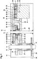
- a stable housing 11 takes on a vehicle frame (not shown), inter alia, the position of the bottom bracket 13 for both sides of the housing 11 outstanding crankshaft 14 with pedals (not shown) for the muscle drive of a hybrid vehicle 10, here a bicycle, with electric motor auxiliary drive 12.
- the introduced muscle power serves as the main drive for locomotion, which can be supported by the auxiliary drive 12 as needed.
- a planetary gear which is preferably designed as a planetary gear 15. This is at least an eccentrically mounted on a concentric rotating carrier 22 planetary gear 20 simultaneously with the outer periphery of a central wheel (sun gear 21) and with the inner periphery of a ring gear 18 in operative connection, in particular in meshing engagement.
- One of these three concentric gear partners (sun 21 - carrier 22 - ring gear 18) is driven by the pedal crankshaft 14 forth with muscle power, and another gear partner of a drive shaft 35 of the drive motor 31 forth with engine power; while the third transmission partner for generating a reaction torque for the output of the superposition resulting from (superposition) torque can run slowed down, but is preferably stopped fixed to the housing. It is understood in the present invention under the partner not only an immediate part of the transmission itself (such as a gear), but also an extension to rotatably coupled or populated, functionally preceding or subsequent construction elements such as levers, shafts or wheels.
- crankshaft 14 is rotatably equipped with a spur gear 16 which meshes with the external teeth 17 of an internally toothed ring gear 18, however, of smaller diameter.
- spur gear 16 which meshes with the external teeth 17 of an internally toothed ring gear 18, however, of smaller diameter.
- planet gears 20 which are mounted eccentrically on a concentrically arranged planetary carrier 22.
- the spur gear planetary gears 20 mesh on the one hand with a sun 21 intervening centrally between them and on the other hand with the internal teeth 19 of the ring gear 18 concentric therewith.
- the planet carrier 22 is rotatably mounted on the central shaft 40; but it is locked by means of a, as molded or attached rigid arm lever 46, support 41 on the housing 11 at a torque measuring device 47 against rotation.
- the term of the lever arm 46 is not limited to the classic standard design in bar form; it extends to any support 41 of the transmission partner in question against an abutment 51, its state of tension, deformation or displacement measure is.
- the lever arm 46 may therefore be designed as an eccentric projection on the transmission partner to be fixed itself or on a disk which is rigidly connected thereto.
- sun 21 in the planetary gear 15 acts at in Fig.1 , Sketched implementation example, the external teeth 23 of a sleeve 24, on which the ring gear 19 is rotatably mounted.
- the offset in the axial direction to the outside of the planetary gear 15 is rotatably mounted in the surrounding housing 11 centrally mounted central shaft 40 with the here designated as coupling gear 25 gear.
- This can, as shown in one piece with the sleeve 24, ie formed with the sun 21 or rotatably connected to it.
- sun 21 and cuff 24 are two axially overlapping portions for rotationally coupling them via a freewheel (not shown).
- the freewheel engages when a sun gear 21 is to be transmitted from the sun 21 in the direction of the output or transmission wheel 28; but it opens when the direction of rotation is reversed by reverse pedaling on the crankshaft 14 together with its spur gear 16, to reliably exclude possible transmission blockages. From comparable For reasons it may be appropriate to further gears in Fig.1 sketched gear on their waves by means of freewheels only in the operating direction to transmit torques (not shown).
- the output shaft 27 rotatably carries a driven or transmission wheel 28 for driving the vehicle 10 via a chain 29 (or, in the case of adapted tooth geometry, via a toothed belt).
- the vehicle 10 can be driven by introducing muscle power on the pedals in the crankshaft 14.
- the coupling wheel 25 also meshes with an intermediate gear 30, via which a drive motor 31 of the auxiliary drive 12 introduces its torque into the output shaft 27 to the transmission wheel 28.
- the drive motor 31 operates on a reduction gear 32, which may be a conventional spur gear or a transmission; but preferably designed as a second planetary gear 33.
- Its sun 34 sits as a pinion torsionally rigid on the axially projecting engine drive shaft 35 and engages between the local planet gears 36 a.
- the roll in the torsionally rigid ring gear 37 and therefore rotate their planet carrier 38 with its coaxial before it rotatably connected drive pinion 39. This meshes with the already mentioned intermediate 30 to the resulting drive torque in addition to the coupling gear 25 and then via the drive wheel 26 in the output shaft 27th feed.
- the intermediate gear 30 may be designed as a double gear to bridge an axial distance between the drive pinion 39, as part of the second drive reduction gear 32, and the coupling wheel 25.
- an additional gear stage for reducing the rotational speed of the additional drive 12 can be realized there via the design of the mutually meshing tooth pair.
- the illustrated gear ratio between the coupling wheel 25 and the drive wheel 26 may represent the first gear of a multi-speed circuit. Then you can switch to other gears (gear ratios) by putting in this area of the Umgephaseuses 11 differently designed such gear pairings 25-26 are provided axially adjacent to each other on the output shaft 27 (not shown), which are selectively effective switchable, so to put in meshing engagement.
- the output shaft 27 is equipped with the drive wheels 26 via freewheels (not shown), so that the lower gears are rolled over by the currently load-bearing gear, without causing blockages.
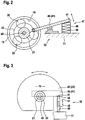
- the eccentric rigid lever arm 46 for stopping one of the gear partners on the measuring unit 47, formed directly on the planet carrier 22 or fixed in the illustrated embodiment; or it is formed with a coaxial extension of the planet carrier 22 axially in front of the planetary gear 15 or arranged, as in Figure 3 outlined.
- the rotatably provided on the planet carrier 22 lever arm 46 may be formed as a centripetal support incision 44 in the manner of aêtsektors in a kink fixed-dimensioned rotating disc 45 or be dimensioned for bending stiff, classical lever arm 46 abstracted.
- the support force occurring at the measuring unit 47 is a measure of the torque taken up by the stopped gear partner, here by the planet carrier 22; and thus also for the introduced with muscle power in the planetary gear 15 torque of the main drive in the form of the crankshaft 14 for locomotion of hybrid drivable vehicle 10.
- a motor control not shown
- more highly controlled auxiliary drive 12 a higher power contribution, and the muscle moment can be withdrawn.
- the deflection of the spring 50 out of its basic position with introduction of force into the abutment 51 on the spring 50 takes place by pivoting the lever arm 46 until torque equilibrium sets. The then reached pivot angle, so indirectly the current spring length can be determined in the measuring unit 47. That can by means of Electrodes for capacitive distance measurement between the housing 11 and the lever arm 46 may be made, generally by means of a distance measuring device 52.
- a plunger coil system may be provided or, for eddy current measurement, a coil printed on a stationary circuit board in the vicinity of about one Copper plate, which is integrated, for example, in a lever arm 46 made of fiber-reinforced plastic.
- strain gauges 48 which are applied to a prismatic sensor rod 49 and are evaluated approximately in bridge circuit. Due to the lack of bending stress, the location of the attachment of the strain gauge transducers along the sensor rod 49 is not critical.
- the metallic sensor rod 49 set by the rigid lever arm 46 via the abutment 51 under tensile or compressive stress is dimensioned longitudinally stress-resistant and kink-proof. So that it is claimed only in the longitudinal direction (on pressure or train), the sensor rod 49 is as sketched at its base and top surfaces preferably hingedly connected to the surrounding housing 11 and to the abutment 51 for the lever arm 46.
- a for a primarily with muscle power to moving vehicle 10 such as a bicycle designed hybrid drive with preferably electric motor auxiliary drive 12 thus has a acted upon by the crankshaft 14 and acted upon by the auxiliary drive 12 transmission, in which one of the Getriebepartner- in a planetary gear 15 one of the three concentric rotatable gear partner (ring gear 18, planet carrier 22 or sun 21) - is locked by means of a rigid lever arm 46 to a housing-fixed torque measuring mechanism 47.
- the measuring unit 47 preferably has a sensor rod 49, which is acted upon by the lever arm 46 in the longitudinal direction.
- a soft-elastic sensor rod 49 may be realized by a coil spring 50; then the angular position of the lever arm 46 is determined at moment equilibrium by means of an approximately capacitive or inductive distance sensor 52 working.
- the supporting moment is detected via its inner longitudinal tension by means of strain gauges 48 applied to the rod outer surface.
Landscapes
- Engineering & Computer Science (AREA)
- Chemical & Material Sciences (AREA)
- Combustion & Propulsion (AREA)
- Transportation (AREA)
- Mechanical Engineering (AREA)
- Physics & Mathematics (AREA)
- General Physics & Mathematics (AREA)
- Electromagnetism (AREA)
- Retarders (AREA)
Applications Claiming Priority (1)
| Application Number | Priority Date | Filing Date | Title |
|---|---|---|---|
| DE202016008403 | 2016-11-14 |
Publications (2)
| Publication Number | Publication Date |
|---|---|
| EP3323701A1 true EP3323701A1 (fr) | 2018-05-23 |
| EP3323701B1 EP3323701B1 (fr) | 2021-12-01 |
Family
ID=62026306
Family Applications (1)
| Application Number | Title | Priority Date | Filing Date |
|---|---|---|---|
| EP17001631.5A Active EP3323701B1 (fr) | 2016-11-14 | 2017-10-05 | Dispositif de détection de couple, en particulier permettant de commander l'entraînement supplémentaire d'un véhicule pourvu d'entraînement hybride propulsé par force musculaire |
Country Status (2)
| Country | Link |
|---|---|
| EP (1) | EP3323701B1 (fr) |
| DE (1) | DE102017010198A1 (fr) |
Cited By (4)
| Publication number | Priority date | Publication date | Assignee | Title |
|---|---|---|---|---|
| WO2018226095A1 (fr) * | 2017-06-06 | 2018-12-13 | Advancing Technologies B.V. | Transmission pour une bicyclette |
| CN109969333A (zh) * | 2019-04-02 | 2019-07-05 | 无锡川克智能电机有限公司 | 基于行星轮系传动系统的电动自行车测扭矩机构 |
| CN113117316A (zh) * | 2019-12-31 | 2021-07-16 | 罗技欧洲公司 | 改进的游戏踏板组件 |
| CN121068069A (zh) * | 2025-11-07 | 2025-12-05 | 歌尔股份有限公司 | 扭矩测试设备 |
Families Citing this family (4)
| Publication number | Priority date | Publication date | Assignee | Title |
|---|---|---|---|---|
| DE102019132715B4 (de) | 2019-12-02 | 2024-03-14 | Ika - Werke Gmbh & Co. Kg | Rührgerät |
| DE102020134254A1 (de) | 2020-12-18 | 2022-06-23 | Frank Scheftlein | Verfahren zur Messung der Trittkraft an einem Tretantrieb und Tretantrieb mit mindestens einem Kraftsensor |
| CN114370997B (zh) * | 2021-12-31 | 2023-06-09 | 重庆大学 | 一种行星轮系内部动态分流测试方法 |
| IT202300011868A1 (it) * | 2023-06-09 | 2024-12-09 | Hgears Padova S P A | Dispositivo di assistenza alla pedalata |
Citations (7)
| Publication number | Priority date | Publication date | Assignee | Title |
|---|---|---|---|---|
| US3034368A (en) * | 1958-08-16 | 1962-05-15 | Reimers Getriebe K G Fa | Apparatus for the automatic control of the output of power supply |
| DE2931230C2 (fr) | 1978-08-03 | 1990-04-05 | Continental Scale Corp., Bridgeview, Ill., Us | |
| JP2000337981A (ja) * | 1999-05-26 | 2000-12-08 | Yamaha Motor Co Ltd | 駆動装置 |
| JP2002331985A (ja) * | 2001-05-31 | 2002-11-19 | Ind Technol Res Inst | 自転車のトルク検出及び大ギア小型化装置 |
| DE102013214395A1 (de) | 2013-07-23 | 2015-01-29 | Soehnle Industrial Solutions Gmbh | Drehmomentmessvorrichtung und Fahrrad mit einer Drehmomentmessvorrichtung |
| EP3012181A1 (fr) * | 2014-10-21 | 2016-04-27 | Wuxi Aimeike Power Machinery Company Limited | Système d'entraînement de moteur intermédiaire pour une bicyclette électrique |
| DE102014009833B4 (de) | 2014-07-02 | 2016-05-19 | Ling He | Antriebseinheit für ein elektrisch unterstütztes Fahrrad. |
Family Cites Families (3)
| Publication number | Priority date | Publication date | Assignee | Title |
|---|---|---|---|---|
| KR20020000578A (ko) * | 2000-06-23 | 2002-01-05 | 안 태 환 | 토크미터 부착형 유성기어장치 |
| CN102620875A (zh) * | 2012-04-09 | 2012-08-01 | 潍柴动力股份有限公司 | 一种扭矩测量仪 |
| CN104052196B (zh) * | 2013-03-13 | 2017-08-25 | 宁波兴隆巨创机电科技有限公司 | 一种用于助力自行车上的电机 |
-
2017
- 2017-10-05 EP EP17001631.5A patent/EP3323701B1/fr active Active
- 2017-11-02 DE DE102017010198.1A patent/DE102017010198A1/de not_active Withdrawn
Patent Citations (7)
| Publication number | Priority date | Publication date | Assignee | Title |
|---|---|---|---|---|
| US3034368A (en) * | 1958-08-16 | 1962-05-15 | Reimers Getriebe K G Fa | Apparatus for the automatic control of the output of power supply |
| DE2931230C2 (fr) | 1978-08-03 | 1990-04-05 | Continental Scale Corp., Bridgeview, Ill., Us | |
| JP2000337981A (ja) * | 1999-05-26 | 2000-12-08 | Yamaha Motor Co Ltd | 駆動装置 |
| JP2002331985A (ja) * | 2001-05-31 | 2002-11-19 | Ind Technol Res Inst | 自転車のトルク検出及び大ギア小型化装置 |
| DE102013214395A1 (de) | 2013-07-23 | 2015-01-29 | Soehnle Industrial Solutions Gmbh | Drehmomentmessvorrichtung und Fahrrad mit einer Drehmomentmessvorrichtung |
| DE102014009833B4 (de) | 2014-07-02 | 2016-05-19 | Ling He | Antriebseinheit für ein elektrisch unterstütztes Fahrrad. |
| EP3012181A1 (fr) * | 2014-10-21 | 2016-04-27 | Wuxi Aimeike Power Machinery Company Limited | Système d'entraînement de moteur intermédiaire pour une bicyclette électrique |
Cited By (5)
| Publication number | Priority date | Publication date | Assignee | Title |
|---|---|---|---|---|
| WO2018226095A1 (fr) * | 2017-06-06 | 2018-12-13 | Advancing Technologies B.V. | Transmission pour une bicyclette |
| CN109969333A (zh) * | 2019-04-02 | 2019-07-05 | 无锡川克智能电机有限公司 | 基于行星轮系传动系统的电动自行车测扭矩机构 |
| CN109969333B (zh) * | 2019-04-02 | 2023-09-05 | 无锡川克智能电机有限公司 | 基于行星轮系传动系统的电动自行车测扭矩机构 |
| CN113117316A (zh) * | 2019-12-31 | 2021-07-16 | 罗技欧洲公司 | 改进的游戏踏板组件 |
| CN121068069A (zh) * | 2025-11-07 | 2025-12-05 | 歌尔股份有限公司 | 扭矩测试设备 |
Also Published As
| Publication number | Publication date |
|---|---|
| EP3323701B1 (fr) | 2021-12-01 |
| DE102017010198A1 (de) | 2018-05-17 |
Similar Documents
| Publication | Publication Date | Title |
|---|---|---|
| EP3323701A1 (fr) | Dispositif de détection de couple, en particulier permettant de commander l'entraînement supplémentaire d'un véhicule pourvu d'entraînement hybride propulsé par force musculaire | |
| EP2986493B1 (fr) | Véhicule entraînable par un moteur et par la force musculaire | |
| EP2986492B1 (fr) | Véhicule entraînable par un moteur et par la force musculaire | |
| DE102014009833B4 (de) | Antriebseinheit für ein elektrisch unterstütztes Fahrrad. | |
| DE69512958T2 (de) | Pedalkraftdetektor für Fahrrad mit Hilfsmotor | |
| DE102013011504B4 (de) | Fahrradantriebseinheit | |
| DE69601972T2 (de) | Pedalkraftdetektor für Fahrrad mit Hilfsmotor | |
| WO2001066338A2 (fr) | Dispositif d'enfoncement | |
| EP2470417B1 (fr) | Unité d'entraînement | |
| DE102010028643A1 (de) | Getriebe für Elektrofahrräder zur Erfassung eines Drehmoments und zugehöriges Verfahren für Elektrofahrräder zur Erfassung eines Drehmoments | |
| EP3450200B1 (fr) | Unité de transmission de moyeu de roue pour un moyeu de roue d'un véhicule, moyeu de roue et véhicule à entraînement auxiliaire | |
| DE102010048592A1 (de) | Tretlagersystem zum beidseitigen Messen des Drehmomentes und der Drehzahl | |
| DE102010003050A1 (de) | Fahrrad | |
| DE102017209652B4 (de) | Anordnung zur Drehmomenterfassung, Antrieb und Arbeitsvorrichtung | |
| CN108068982B (zh) | 检测转矩、控制混合驱动的车辆的附加驱动装置的装置 | |
| DE102010018658A1 (de) | Mittel zur Messung der Pedalkräfte, Auswertung und oder Gangwahl am Fahrrad | |
| DE102011012311A1 (de) | Elektromechanische Lenkung | |
| DE102011087784A1 (de) | Kurbeltrieb für ein Fahrrad | |
| DE69707738T2 (de) | Fahrrad mit Hilfsmotor | |
| DE102015201815B3 (de) | Zahnkranzpaket und zugehöriger Antriebsstrang | |
| EP1431161B1 (fr) | Système de direction pour un véhicule | |
| DE102010026810A1 (de) | Elektrofahrrad mit Elektromotor | |
| DE102013214395B4 (de) | Drehmomentmessvorrichtung und Fahrrad mit einer Drehmomentmessvorrichtung | |
| DE102018209908A1 (de) | Getriebe mit einer Messeinrichtung | |
| DE102024208813A1 (de) | Antriebsanordnung |
Legal Events
| Date | Code | Title | Description |
|---|---|---|---|
| PUAI | Public reference made under article 153(3) epc to a published international application that has entered the european phase |
Free format text: ORIGINAL CODE: 0009012 |
|
| STAA | Information on the status of an ep patent application or granted ep patent |
Free format text: STATUS: THE APPLICATION HAS BEEN PUBLISHED |
|
| AK | Designated contracting states |
Kind code of ref document: A1 Designated state(s): AL AT BE BG CH CY CZ DE DK EE ES FI FR GB GR HR HU IE IS IT LI LT LU LV MC MK MT NL NO PL PT RO RS SE SI SK SM TR |
|
| AX | Request for extension of the european patent |
Extension state: BA ME |
|
| STAA | Information on the status of an ep patent application or granted ep patent |
Free format text: STATUS: REQUEST FOR EXAMINATION WAS MADE |
|
| 17P | Request for examination filed |
Effective date: 20181017 |
|
| RAP1 | Party data changed (applicant data changed or rights of an application transferred) |
Owner name: OECHSLER AG |
|
| RBV | Designated contracting states (corrected) |
Designated state(s): AL AT BE BG CH CY CZ DE DK EE ES FI FR GB GR HR HU IE IS IT LI LT LU LV MC MK MT NL NO PL PT RO RS SE SI SK SM TR |
|
| STAA | Information on the status of an ep patent application or granted ep patent |
Free format text: STATUS: EXAMINATION IS IN PROGRESS |
|
| 17Q | First examination report despatched |
Effective date: 20200331 |
|
| GRAP | Despatch of communication of intention to grant a patent |
Free format text: ORIGINAL CODE: EPIDOSNIGR1 |
|
| STAA | Information on the status of an ep patent application or granted ep patent |
Free format text: STATUS: GRANT OF PATENT IS INTENDED |
|
| INTG | Intention to grant announced |
Effective date: 20210528 |
|
| GRAS | Grant fee paid |
Free format text: ORIGINAL CODE: EPIDOSNIGR3 |
|
| GRAA | (expected) grant |
Free format text: ORIGINAL CODE: 0009210 |
|
| STAA | Information on the status of an ep patent application or granted ep patent |
Free format text: STATUS: THE PATENT HAS BEEN GRANTED |
|
| AK | Designated contracting states |
Kind code of ref document: B1 Designated state(s): AL AT BE BG CH CY CZ DE DK EE ES FI FR GB GR HR HU IE IS IT LI LT LU LV MC MK MT NL NO PL PT RO RS SE SI SK SM TR |
|
| REG | Reference to a national code |
Ref country code: GB Ref legal event code: FG4D Free format text: NOT ENGLISH |
|
| REG | Reference to a national code |
Ref country code: AT Ref legal event code: REF Ref document number: 1451514 Country of ref document: AT Kind code of ref document: T Effective date: 20211215 Ref country code: CH Ref legal event code: EP |
|
| REG | Reference to a national code |
Ref country code: IE Ref legal event code: FG4D Free format text: LANGUAGE OF EP DOCUMENT: GERMAN |
|
| REG | Reference to a national code |
Ref country code: DE Ref legal event code: R096 Ref document number: 502017012118 Country of ref document: DE |
|
| REG | Reference to a national code |
Ref country code: LT Ref legal event code: MG9D |
|
| REG | Reference to a national code |
Ref country code: NL Ref legal event code: MP Effective date: 20211201 |
|
| PG25 | Lapsed in a contracting state [announced via postgrant information from national office to epo] |
Ref country code: RS Free format text: LAPSE BECAUSE OF FAILURE TO SUBMIT A TRANSLATION OF THE DESCRIPTION OR TO PAY THE FEE WITHIN THE PRESCRIBED TIME-LIMIT Effective date: 20211201 Ref country code: LT Free format text: LAPSE BECAUSE OF FAILURE TO SUBMIT A TRANSLATION OF THE DESCRIPTION OR TO PAY THE FEE WITHIN THE PRESCRIBED TIME-LIMIT Effective date: 20211201 Ref country code: FI Free format text: LAPSE BECAUSE OF FAILURE TO SUBMIT A TRANSLATION OF THE DESCRIPTION OR TO PAY THE FEE WITHIN THE PRESCRIBED TIME-LIMIT Effective date: 20211201 Ref country code: BG Free format text: LAPSE BECAUSE OF FAILURE TO SUBMIT A TRANSLATION OF THE DESCRIPTION OR TO PAY THE FEE WITHIN THE PRESCRIBED TIME-LIMIT Effective date: 20220301 |
|
| PG25 | Lapsed in a contracting state [announced via postgrant information from national office to epo] |
Ref country code: SE Free format text: LAPSE BECAUSE OF FAILURE TO SUBMIT A TRANSLATION OF THE DESCRIPTION OR TO PAY THE FEE WITHIN THE PRESCRIBED TIME-LIMIT Effective date: 20211201 Ref country code: PL Free format text: LAPSE BECAUSE OF FAILURE TO SUBMIT A TRANSLATION OF THE DESCRIPTION OR TO PAY THE FEE WITHIN THE PRESCRIBED TIME-LIMIT Effective date: 20211201 Ref country code: NO Free format text: LAPSE BECAUSE OF FAILURE TO SUBMIT A TRANSLATION OF THE DESCRIPTION OR TO PAY THE FEE WITHIN THE PRESCRIBED TIME-LIMIT Effective date: 20220301 Ref country code: LV Free format text: LAPSE BECAUSE OF FAILURE TO SUBMIT A TRANSLATION OF THE DESCRIPTION OR TO PAY THE FEE WITHIN THE PRESCRIBED TIME-LIMIT Effective date: 20211201 Ref country code: HR Free format text: LAPSE BECAUSE OF FAILURE TO SUBMIT A TRANSLATION OF THE DESCRIPTION OR TO PAY THE FEE WITHIN THE PRESCRIBED TIME-LIMIT Effective date: 20211201 Ref country code: GR Free format text: LAPSE BECAUSE OF FAILURE TO SUBMIT A TRANSLATION OF THE DESCRIPTION OR TO PAY THE FEE WITHIN THE PRESCRIBED TIME-LIMIT Effective date: 20220302 Ref country code: ES Free format text: LAPSE BECAUSE OF FAILURE TO SUBMIT A TRANSLATION OF THE DESCRIPTION OR TO PAY THE FEE WITHIN THE PRESCRIBED TIME-LIMIT Effective date: 20211201 |
|
| PG25 | Lapsed in a contracting state [announced via postgrant information from national office to epo] |
Ref country code: NL Free format text: LAPSE BECAUSE OF FAILURE TO SUBMIT A TRANSLATION OF THE DESCRIPTION OR TO PAY THE FEE WITHIN THE PRESCRIBED TIME-LIMIT Effective date: 20211201 |
|
| PG25 | Lapsed in a contracting state [announced via postgrant information from national office to epo] |
Ref country code: SM Free format text: LAPSE BECAUSE OF FAILURE TO SUBMIT A TRANSLATION OF THE DESCRIPTION OR TO PAY THE FEE WITHIN THE PRESCRIBED TIME-LIMIT Effective date: 20211201 Ref country code: SK Free format text: LAPSE BECAUSE OF FAILURE TO SUBMIT A TRANSLATION OF THE DESCRIPTION OR TO PAY THE FEE WITHIN THE PRESCRIBED TIME-LIMIT Effective date: 20211201 Ref country code: RO Free format text: LAPSE BECAUSE OF FAILURE TO SUBMIT A TRANSLATION OF THE DESCRIPTION OR TO PAY THE FEE WITHIN THE PRESCRIBED TIME-LIMIT Effective date: 20211201 Ref country code: PT Free format text: LAPSE BECAUSE OF FAILURE TO SUBMIT A TRANSLATION OF THE DESCRIPTION OR TO PAY THE FEE WITHIN THE PRESCRIBED TIME-LIMIT Effective date: 20220401 Ref country code: EE Free format text: LAPSE BECAUSE OF FAILURE TO SUBMIT A TRANSLATION OF THE DESCRIPTION OR TO PAY THE FEE WITHIN THE PRESCRIBED TIME-LIMIT Effective date: 20211201 Ref country code: CZ Free format text: LAPSE BECAUSE OF FAILURE TO SUBMIT A TRANSLATION OF THE DESCRIPTION OR TO PAY THE FEE WITHIN THE PRESCRIBED TIME-LIMIT Effective date: 20211201 |
|
| REG | Reference to a national code |
Ref country code: DE Ref legal event code: R097 Ref document number: 502017012118 Country of ref document: DE |
|
| PG25 | Lapsed in a contracting state [announced via postgrant information from national office to epo] |
Ref country code: IS Free format text: LAPSE BECAUSE OF FAILURE TO SUBMIT A TRANSLATION OF THE DESCRIPTION OR TO PAY THE FEE WITHIN THE PRESCRIBED TIME-LIMIT Effective date: 20220401 |
|
| PLBE | No opposition filed within time limit |
Free format text: ORIGINAL CODE: 0009261 |
|
| STAA | Information on the status of an ep patent application or granted ep patent |
Free format text: STATUS: NO OPPOSITION FILED WITHIN TIME LIMIT |
|
| PG25 | Lapsed in a contracting state [announced via postgrant information from national office to epo] |
Ref country code: DK Free format text: LAPSE BECAUSE OF FAILURE TO SUBMIT A TRANSLATION OF THE DESCRIPTION OR TO PAY THE FEE WITHIN THE PRESCRIBED TIME-LIMIT Effective date: 20211201 Ref country code: AL Free format text: LAPSE BECAUSE OF FAILURE TO SUBMIT A TRANSLATION OF THE DESCRIPTION OR TO PAY THE FEE WITHIN THE PRESCRIBED TIME-LIMIT Effective date: 20211201 |
|
| 26N | No opposition filed |
Effective date: 20220902 |
|
| PG25 | Lapsed in a contracting state [announced via postgrant information from national office to epo] |
Ref country code: SI Free format text: LAPSE BECAUSE OF FAILURE TO SUBMIT A TRANSLATION OF THE DESCRIPTION OR TO PAY THE FEE WITHIN THE PRESCRIBED TIME-LIMIT Effective date: 20211201 |
|
| PG25 | Lapsed in a contracting state [announced via postgrant information from national office to epo] |
Ref country code: MC Free format text: LAPSE BECAUSE OF FAILURE TO SUBMIT A TRANSLATION OF THE DESCRIPTION OR TO PAY THE FEE WITHIN THE PRESCRIBED TIME-LIMIT Effective date: 20211201 Ref country code: IT Free format text: LAPSE BECAUSE OF FAILURE TO SUBMIT A TRANSLATION OF THE DESCRIPTION OR TO PAY THE FEE WITHIN THE PRESCRIBED TIME-LIMIT Effective date: 20211201 |
|
| REG | Reference to a national code |
Ref country code: CH Ref legal event code: PL |
|
| REG | Reference to a national code |
Ref country code: BE Ref legal event code: MM Effective date: 20221031 |
|
| GBPC | Gb: european patent ceased through non-payment of renewal fee |
Effective date: 20221005 |
|
| PG25 | Lapsed in a contracting state [announced via postgrant information from national office to epo] |
Ref country code: LU Free format text: LAPSE BECAUSE OF NON-PAYMENT OF DUE FEES Effective date: 20221005 |
|
| P01 | Opt-out of the competence of the unified patent court (upc) registered |
Effective date: 20230601 |
|
| PG25 | Lapsed in a contracting state [announced via postgrant information from national office to epo] |
Ref country code: LI Free format text: LAPSE BECAUSE OF NON-PAYMENT OF DUE FEES Effective date: 20221031 Ref country code: FR Free format text: LAPSE BECAUSE OF NON-PAYMENT OF DUE FEES Effective date: 20221031 Ref country code: CH Free format text: LAPSE BECAUSE OF NON-PAYMENT OF DUE FEES Effective date: 20221031 |
|
| PG25 | Lapsed in a contracting state [announced via postgrant information from national office to epo] |
Ref country code: BE Free format text: LAPSE BECAUSE OF NON-PAYMENT OF DUE FEES Effective date: 20221031 |
|
| PG25 | Lapsed in a contracting state [announced via postgrant information from national office to epo] |
Ref country code: IE Free format text: LAPSE BECAUSE OF NON-PAYMENT OF DUE FEES Effective date: 20221005 Ref country code: GB Free format text: LAPSE BECAUSE OF NON-PAYMENT OF DUE FEES Effective date: 20221005 |
|
| REG | Reference to a national code |
Ref country code: AT Ref legal event code: MM01 Ref document number: 1451514 Country of ref document: AT Kind code of ref document: T Effective date: 20221005 |
|
| PG25 | Lapsed in a contracting state [announced via postgrant information from national office to epo] |
Ref country code: AT Free format text: LAPSE BECAUSE OF NON-PAYMENT OF DUE FEES Effective date: 20221005 |
|
| PG25 | Lapsed in a contracting state [announced via postgrant information from national office to epo] |
Ref country code: HU Free format text: LAPSE BECAUSE OF FAILURE TO SUBMIT A TRANSLATION OF THE DESCRIPTION OR TO PAY THE FEE WITHIN THE PRESCRIBED TIME-LIMIT; INVALID AB INITIO Effective date: 20171005 |
|
| PG25 | Lapsed in a contracting state [announced via postgrant information from national office to epo] |
Ref country code: CY Free format text: LAPSE BECAUSE OF FAILURE TO SUBMIT A TRANSLATION OF THE DESCRIPTION OR TO PAY THE FEE WITHIN THE PRESCRIBED TIME-LIMIT Effective date: 20211201 |
|
| PG25 | Lapsed in a contracting state [announced via postgrant information from national office to epo] |
Ref country code: MK Free format text: LAPSE BECAUSE OF FAILURE TO SUBMIT A TRANSLATION OF THE DESCRIPTION OR TO PAY THE FEE WITHIN THE PRESCRIBED TIME-LIMIT Effective date: 20211201 |
|
| PG25 | Lapsed in a contracting state [announced via postgrant information from national office to epo] |
Ref country code: TR Free format text: LAPSE BECAUSE OF FAILURE TO SUBMIT A TRANSLATION OF THE DESCRIPTION OR TO PAY THE FEE WITHIN THE PRESCRIBED TIME-LIMIT Effective date: 20211201 |
|
| PG25 | Lapsed in a contracting state [announced via postgrant information from national office to epo] |
Ref country code: MT Free format text: LAPSE BECAUSE OF FAILURE TO SUBMIT A TRANSLATION OF THE DESCRIPTION OR TO PAY THE FEE WITHIN THE PRESCRIBED TIME-LIMIT Effective date: 20211201 |
|
| PGFP | Annual fee paid to national office [announced via postgrant information from national office to epo] |
Ref country code: DE Payment date: 20241022 Year of fee payment: 8 |