EP3323711A1 - Sperrbares verriegelungsystem für eine verschiebbare triebwerksgondelstruktur - Google Patents
Sperrbares verriegelungsystem für eine verschiebbare triebwerksgondelstruktur Download PDFInfo
- Publication number
- EP3323711A1 EP3323711A1 EP17202441.6A EP17202441A EP3323711A1 EP 3323711 A1 EP3323711 A1 EP 3323711A1 EP 17202441 A EP17202441 A EP 17202441A EP 3323711 A1 EP3323711 A1 EP 3323711A1
- Authority
- EP
- European Patent Office
- Prior art keywords
- component
- lock
- fanlet
- track
- bolt
- Prior art date
- Legal status (The legal status is an assumption and is not a legal conclusion. Google has not performed a legal analysis and makes no representation as to the accuracy of the status listed.)
- Granted
Links
Images


Classifications
-
- B—PERFORMING OPERATIONS; TRANSPORTING
- B64—AIRCRAFT; AVIATION; COSMONAUTICS
- B64D—EQUIPMENT FOR FITTING IN OR TO AIRCRAFT; FLIGHT SUITS; PARACHUTES; ARRANGEMENT OR MOUNTING OF POWER PLANTS OR PROPULSION TRANSMISSIONS IN AIRCRAFT
- B64D29/00—Power-plant nacelles, fairings or cowlings
- B64D29/06—Attaching of nacelles, fairings or cowlings
-
- B—PERFORMING OPERATIONS; TRANSPORTING
- B64—AIRCRAFT; AVIATION; COSMONAUTICS
- B64C—AEROPLANES; HELICOPTERS
- B64C7/00—Structures or fairings not otherwise provided for
- B64C7/02—Nacelles
-
- F—MECHANICAL ENGINEERING; LIGHTING; HEATING; WEAPONS; BLASTING
- F02—COMBUSTION ENGINES; HOT-GAS OR COMBUSTION-PRODUCT ENGINE PLANTS
- F02K—JET-PROPULSION PLANTS
- F02K1/00—Plants characterised by the form or arrangement of the jet pipe or nozzle; Jet pipes or nozzles peculiar thereto
- F02K1/54—Nozzles having means for reversing jet thrust
- F02K1/64—Reversing fan flow
- F02K1/70—Reversing fan flow using thrust reverser flaps or doors mounted on the fan housing
- F02K1/72—Reversing fan flow using thrust reverser flaps or doors mounted on the fan housing the aft end of the fan housing being movable to uncover openings in the fan housing for the reversed flow
-
- F—MECHANICAL ENGINEERING; LIGHTING; HEATING; WEAPONS; BLASTING
- F05—INDEXING SCHEMES RELATING TO ENGINES OR PUMPS IN VARIOUS SUBCLASSES OF CLASSES F01-F04
- F05D—INDEXING SCHEME FOR ASPECTS RELATING TO NON-POSITIVE-DISPLACEMENT MACHINES OR ENGINES, GAS-TURBINES OR JET-PROPULSION PLANTS
- F05D2220/00—Application
- F05D2220/30—Application in turbines
- F05D2220/32—Application in turbines in gas turbines
- F05D2220/323—Application in turbines in gas turbines for aircraft propulsion, e.g. jet engines
-
- F—MECHANICAL ENGINEERING; LIGHTING; HEATING; WEAPONS; BLASTING
- F05—INDEXING SCHEMES RELATING TO ENGINES OR PUMPS IN VARIOUS SUBCLASSES OF CLASSES F01-F04
- F05D—INDEXING SCHEME FOR ASPECTS RELATING TO NON-POSITIVE-DISPLACEMENT MACHINES OR ENGINES, GAS-TURBINES OR JET-PROPULSION PLANTS
- F05D2260/00—Function
- F05D2260/50—Kinematic linkage, i.e. transmission of position
- F05D2260/52—Kinematic linkage, i.e. transmission of position involving springs
Definitions
- This disclosure relates generally to an aircraft propulsion system and, more particularly, to a nacelle with at least one translatable structure such as, for example, a translating fanlet.
- translatable structure such as a fanlet that axially translates between an open position and a closed position.
- a typical lock for such a translatable structure is only operable to secure that translatable structure in the closed position.
- inadvertent / accidental movement of the translatable structure when open may cause injury to maintenance personnel. Therefore, there is a need in the art for a system capable of securing the translatable structure in a closed position as well as an open position.
- an assembly for an aircraft propulsion system.
- This assembly includes a fanlet and a track system configured to enable axial translation of the fanlet along a centerline between an open position and a closed position.
- the track system includes a first component, a second component and a lock.
- One of the first and the second components is configured as or otherwise includes a slider.
- the other one of the first and the second components includes or otherwise includes a track.
- the slider is mated with and configured to slide axially along the track.
- the lock includes or otherwise includes a bolt mounted with the first component. The lock is configured to move the bolt laterally into an aperture in the second component to prevent axial translation of the fanlet.
- an assembly for an aircraft propulsion system.
- This assembly includes a nacelle structure which is configured as or otherwise includes a cowl.
- the assembly also includes a track system configured to enable axial translation of the nacelle structure along a centerline between an open position and a closed position.
- the track system includes a first component, a second component and a lock.
- the first component is configured as or otherwise includes an axially extending slider.
- the second component is configured as or otherwise includes an axially extending track.
- the first component is fixedly mounted with the cowl.
- the slider is mated with and configured to slide axially along the track.
- the lock is configured as or otherwise includes a bolt mounted with the first component. The lock is configured to move the bolt laterally into an aperture in the second component to prevent axial translation of the fanlet.
- an assembly for an aircraft propulsion system.
- This assembly includes a nacelle structure which is configured as or otherwise includes a cowl.
- the assembly also includes a track system configured to enable axial translation of the fanlet along a centerline between an open position and a closed position.
- the track system includes a first component, a second component and a lock.
- the first component is configured as or otherwise includes an axially extending slider.
- the second component is configured as or otherwise includes an axially extending track.
- the slider is mated with and configured to slide axially along the track.
- the lock is configured to engage a first aperture in the second component to prevent axial translation of the nacelle structure at the closed position.
- the lock is further configured to engage a second aperture in the second component to prevent axial translation of the nacelle structure at the open position.
- the lock may be configured as or otherwise include a bolt mounted with the first component.
- the lock may be configured to move the bolt laterally into the first aperture at the closed position and laterally into the second aperture at the open position.
- the lock may be spring loaded.
- the track system may further include a third component, a fourth component and a second lock.
- the third component may be configured as or otherwise include an axially extending second slider.
- the fourth component may be configured as or otherwise include an axially extending second track.
- the second slider may be mated with and configured to slide axially along the second track.
- the second lock may be configured to engage a third aperture in the second component to prevent axial translation of the nacelle structure at the closed position.
- the second lock may be further configured to engage a fourth aperture in the second component to prevent axial translation of the nacelle structure at the open position.
- the lock may be configured to move the bolt laterally into the aperture in the second component when the fanlet is in the closed position.
- the lock may be configured to move the bolt laterally into a second aperture in the second component to prevent axial translation of the fanlet when the fanlet is in the open position.
- the lock may be configured to move the bolt laterally into the aperture in the second component when the fanlet is in the open position.
- the slider may be mounted to the fanlet.
- the track may be mounted to a fan case.
- the track may also or alternatively be mounted to another static structure.
- the first component is mounted with the fanlet and the second component is mounted with a static structure.
- This static structure may be a fan case.
- the bolt may be spring loaded.
- the lock may further include a fixed base.
- a threaded portion of the bolt may be mated with a threaded aperture in the fixed base.
- the lock may be operable to be actuated by a driver tool.
- a spring loaded access door may be included and configured to close an access port in the fanlet.
- the lock may be accessible from an exterior of the fanlet through the access port.
- the lock may be accessible by pushing the access door inward from the exterior of the fanlet.
- the track system may further include a third component, a fourth component and a second lock.
- One of the third and the fourth components may be configured as or otherwise include a second slider.
- the other one of the third and the fourth components may be configured as or otherwise include a second track.
- the second slider may be mated with and configured to slide axially along the second track.
- the second lock may be configured as or otherwise include a second bolt mounted with the third component.
- the second lock may be configured to move the second bolt laterally into a second aperture in the fourth component to prevent axial translation of the fanlet.
- the fanlet may be configured as or otherwise include an inlet structure and a fan cowl.
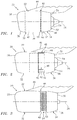
- FIG. 1 illustrates an aircraft propulsion system 20 for an aircraft such as a commercial airliner.
- the propulsion system 20 includes a nacelle 22 and a gas turbine engine.
- This gas turbine engine may be configured as a turbofan engine.
- the gas turbine engine may be configured as a turbojet engine or any other type of gas turbine engine capable of propelling the aircraft.
- the propulsion system 20 may also include a thrust reverser system 24 configured with the nacelle 22; see also FIG. 3 .
- the nacelle 22 may be configured without the thrust reverser system 24.
- the nacelle 22 of FIG. 1 circumscribes the gas turbine engine to provide an aerodynamic covering for the gas turbine engine.
- the nacelle 22 also forms a bypass gas path with the gas turbine engine, whereby air from the engine's turbofan is routed through the bypass gas path and around a core of the gas turbine engine and generates a majority (e.g., more than 75%) of engine thrust out of the aircraft propulsion system 20 in the case of a turbofan engine configuration.
- the nacelle 22 extends along an axial centerline 26 between a forward nacelle end 28 and an aft nacelle end 30.
- the nacelle 22 includes a forward nacelle structure 32 and an aft nacelle structure 34.
- the forward nacelle structure 32 may be configured as a fanlet, and is referred to below as fanlet 32 for ease of description.
- This fanlet 32 includes an inlet structure 36 (e.g., cowl or module) and a fan cowl 38.
- the fanlet 32 may also include one or more additional structures / components such as an acoustic inner barrel, etc.
- the inlet structure 36 is disposed at the forward nacelle end 28.
- the inlet structure 36 is configured to direct a stream of air through an inlet orifice at the forward nacelle end 28 and into the propulsion system 20 towards the gas turbine engine.
- the fan cowl 38 is disposed at an aft end 40 of the fanlet 32 and extends axially between the inlet structure 36 and the aft nacelle structure 34.
- the fan cowl 38 may be generally axially aligned with a fan section of the gas turbine engine.
- the fan cowl 38 is configured to provide an aerodynamic covering for a fan case 42 (see also FIG. 2 ) which circumscribes the fan section.
- the fanlet 32 is configured as a cohesive, translatable structure.
- the inlet structure 36 forms a forward portion of the fanlet 32 and the fan cowl 38 forms an aft portion of the fanlet 32.
- the fanlet 32 is slidably connected to a static structure 44, for example the fan case 42 and/or a pylon structure 46 and/or another static engine structure, through a track system 48, where the track system 48 provides a translatable joint between the fanlet 32 and the static structure 44 as described below in further detail.
- the entire fanlet 32 including the inlet structure 36 and the fan cowl 38 may translate axially along the centerline 26 as shown in FIGS. 1 and 2 .
- the fanlet 32 may thereby move axially between a closed / stowed position (see FIG. 1 ) and a fully open / deployed position, where FIG. 2 illustrates the fanlet 32 in a partially-open / deployed position.
- the inlet structure 36 and the fan cowl 38 provide the functionality described above.
- the fanlet 32 In the partially-open position and the fully open position, the fanlet 32 at least partially (or substantially completely) uncovers at least the fan case 42 and devices and systems mounted thereto (not shown for ease of illustration). This may facilitate propulsion system 20 assembly and maintenance.
- the aft nacelle structure 34 is disposed at the aft nacelle end 30 and extends axially between a forward end 50 thereof and the aft nacelle end 30.
- the aft nacelle structure 34 is configured to provide an outer boundary for an axial portion of the bypass gas path, which extends through the propulsion system 20 to a bypass gas path exhaust nozzle 52.
- the aft nacelle structure 34 may also form the exhaust nozzle 52 in conjunction with an inner fairing assembly 54 (e.g., an inner fixed structure), which houses the core of the gas turbine engine.
- the aft nacelle structure 34 may be configured as or otherwise include a thrust reverser sleeve 56 for the thrust reverser system 24, which may also be referred to as a translating sleeve.
- the aft nacelle structure 34 may also include other components such as, but not limited to, blocker doors, etc.
- the thrust reverser sleeve 56 may have a substantially tubular unitary sleeve body; e.g., may extend more than three-hundred and thirty degrees (330°) around the centerline 26.
- the thrust reverser sleeve 56 may include a pair of sleeve segments (e.g., halves) arranged on opposing sides of the propulsion system 20.
- the present disclosure is not limited to the foregoing exemplary sleeve configurations.
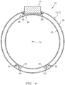
- FIG. 4 schematically illustrates an embodiment of the track system 48.
- This track system 48 is configured to enable axial translation of the fanlet 32 along the centerline 26 between an open position and a closed position.
- the track system 48 thereby provides a translatable joint between the fanlet 32 and the static structure 44 as set forth above.
- the track system 48 may include one or more translatable joint assemblies.
- the track system 48 of FIG. 4 for example, includes a pair of upper joint assemblies 58, a first pair of lower joint assemblies 59 and a second pair of lower joint assemblies 60.
- the upper joint assemblies 58 are arranged on opposing sides of the pylon structure 46.
- the upper joint assemblies 58 are also arranged adjacent to the sides of the pylon structure 46.
- the first pair of lower joint assemblies 59 are arranged approximately at a five-o'clock position.
- the second pair of lower joint assemblies 60 are arranged approximately at a seven-o'clock position.
- the present disclosure is not limited to the foregoing exemplary number and placement of the translatable joint assemblies.
- one of the joint assemblies 59, 60 in each of the lower pairs may be omitted.
- the lower pairs of joint assemblies 59 and 60 may be replaced by a single translatable joint assembly or a pair of translatable joint assemblies at the six-o'clock position.
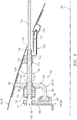
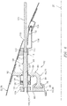
- FIGS. 5 and 6 are sectional diagrammatic illustrations of an exemplary translatable joint assembly 62.
- This translatable joint assembly 62 is representative of a general configuration of each of the translatable joint assemblies 58-60 of FIG. 4 .
- one or more of the translatable joint assemblies 58-60 of FIG. 4 may have a different configuration than that shown in FIGS. 5 and 6 .
- the present disclosure therefore is not limited to the specific translatable joint assembly of FIGS. 5 and 6 .
- the translatable joint assembly 62 of FIGS. 5 and 6 includes a component 64, a component 66 and a lock 68.
- the component 64 may be configured as or otherwise include a slider rail 70.
- this slider rail 70 has a longitudinal length 72 that extends axially along the centerline 26 between a slider forward end 74 and a slider aft end 76.
- the slider rail 70 includes a slider 78 (e.g., a lug) that extends axially and, for example, uninterrupted between the slider forward end 74 and the slider aft end 76.
- the slider 78 of FIG. 5 has a double lobed cross-section. However, in other embodiments, the slider 78 may have other cross-sections; e.g., a single lobed (e.g., circular or oval) cross-section.
- the slider rail 70 also includes a slider mounting bracket 80 that fixedly mounts the slider 78 to the fanlet 32; e.g., the fan cowl 38.
- the slider mounting bracket 80 of FIG. 5 includes a base 82, a web 84 and a flange 86.
- the base 82 is mechanically fastened, bonded (e.g., welded, brazed, adhered, etc.) and/or otherwise attached to the fanlet 32; e.g., the fan cowl 38.
- the web 84 extends between and connects the base 82 and the flange 86.
- the flange 86 projects out from a distal end of the web 84 to the slider 78.
- the flange 86 may be arranged approximately perpendicular to the web 84 such that the flange 86 is generally horizontal and the web 84 is generally vertical relative to gravity.
- the present disclosure is not limited to such a gravitational orientation or exemplary slider mounting bracket configuration.
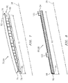
- the component 66 may be configured as or otherwise include a track rail 88.
- this track rail 88 has a longitudinal length 90 that extends axially along the centerline 26 between a track forward end 92 and a track aft end 94.
- This longitudinal length 90 may be substantially equal to (or greater or less than) the longitudinal length 72 of the slider rail 70.
- the track rail 88 includes a track 96 (e.g., a C-channel) that extends axially and, for example, uninterrupted between the track forward end 92 and the track aft end 94.
- the track 96 is configured to receive the slider 78 within a channel thereof. In this manner, the slider 78 is mated with and configured to slide axially along the track 96.
- the track rail 88 also includes a track mounting bracket 98 that fixedly mounts the track 96 to the static structure 44 (see FIG. 4 ); e.g., the pylon structure 46 and/or the fan case 42.
- a track mounting bracket 98 that fixedly mounts the track 96 to the static structure 44 (see FIG. 4 ); e.g., the pylon structure 46 and/or the fan case 42.
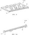
- Specific exemplary embodiments of such a track mounting bracket 98 are illustrated in FIGS. 9 and 10 ; however, the present disclosure is not limited to such exemplary configurations.
- the track mounting bracket 98 includes one or more bolt apertures 100 and 102. These bolt apertures 100 and 102 are arranged along the longitudinal length 90 of the track rail 88 adjacent the track 96 as best shown in FIG. 8 . Each of these bolt apertures 100, 102 extends laterally through the bracket 98.
- Each bolt aperture 100, 102 may also extend laterally through a reinforcement portion 104 of the bracket 98 (see FIGS. 5 and 6 ); e.g., a grommet. However, in other embodiments, one or more of the bolt apertures 100 and 102 may extend laterally into the bracket 98 from the side of the bracket 98 on which the track 96 is mounted and disposed.
- the lock 68 is configured to substantially prevent axial translation of the fanlet 32 when the fanlet 32 is in the closed position and/or the open position. More particularly, the lock 68 is configured to engage the aperture 100 (see also FIG. 8 ) when the fanlet 32 is in the closed position (e.g., see FIG. 1 ). The lock 68 is configured to engage the aperture 102 (see also FIG. 8 ) when the fanlet 32 is in an open position.
- the lock 68 of FIGS. 5 and 6 includes a bolt 106 (e.g., generally cylindrical pin) and a housing 108.
- the housing 108 is fixedly mounted to the fanlet 32 (e.g., the fan cowl 38) adjacent an access port 110; e.g., a through-hole.
- the housing 108 includes a fixed base 112 with a threaded aperture 114.
- the threaded aperture 114 extends laterally through the fixed base 112 and is aligned (e.g., co-axial) with and laterally between the access port 110 and an aperture 116 in the slider mounting bracket 80 (e.g., the web 84).
- a threaded portion 118 of the bolt 106 is mated with and extends through the threaded aperture 114.
- An intermediate portion 120 of the bolt 106 is mated with and extends through the aperture 116.
- An outer distal end of the bolt 106 includes an engagement feature 122 (e.g., a hexagonal socket), which enable a tool such as a driver 124 (e.g., a hexagonal driver tool) to engage the bolt 106 through the access port 110.
- the driver 124 may be manipulated (e.g., manually by hand) to spin the bolt 106 about a longitudinal axis thereof.
- the threaded connection between the bolt 106 and the fixed base 112 translates the spinning motion of the bolt 106 into lateral motion of the bolt 106 along the longitudinal axis. In this manner, an inner distal end of the bolt 106 may be moved laterally into the aperture 100, 102 (see FIG. 6 ) to prevent lateral translation of the fanlet 32, and out of the aperture 100, 102 (see FIG. 5 ) to enable lateral translation of the fanlet 32.
- the bolt 106 and, thus, the lock 68 may be spring loaded.
- the bolt 106 may extend through a bore of a coil spring 126.
- This coil spring 126 may be located laterally between a shoulder 128 on the bolt 106 and a spring housing 130 attached to the slider mounting bracket 80. With this arrangement, the coil spring 126 biases the bolt 106 towards its disengaged position; e.g., where the inner distal end of the bolt 106 is disengaged from the aperture 100, 102 and the track mounting bracket 98.
- An access door 132 may be mounted to the housing 108. When open, the access door 132 is configured to allow the driver 124 access to the bolt 106 through the access port 110. When closed, the access door 132 is configured to close the access port 110.
- the access door 132 may be spring loaded via a torsional spring 134 to prevent or reduce unwanted opening of the access door 132 during propulsion system 20 operation.
- the access door 132 may include a plug portion 136 configured to provide the fanlet 32 with a substantially smooth and continuous aerodynamic surface 138 proximate the access port 100 when the access door 132 is closed by the spring 134.
- the spring 134 may bias the access door 132 against the fanlet 32 and thereby help to maintain the aerodynamic surface 138 of FIG. 11 .
- the lock 68 is accessible from an exterior of the fanlet 32 through the access port 110, for example, by pushing the access door 132 inward from the exterior of the fanlet 32.
- markings 140 may be provided on the fanlet 32 proximate the access port 110 to facilitate engagement and disengagement of the lock 68.
- Each of the translatable joint assemblies 58-60 is described above as including a lock. However, in other embodiments, one or more of the translatable joint assemblies 58-60 of FIG. 4 may be configured without a lock. For example, only one of the two translatable joint assemblies 59, 60 in the lower pairs may include a lock.
- the arrangement of the component 64 and the component 66 may be reversed.
- the track rail 88 is mounted to the fanlet 32 and the slider rail 70 is mounted to the static structure 44.
- the lock 68 is mounted with the track rail 88 rather than the slider rail 70.
- one or more of the translatable joint assemblies 58-60 may include additional bolt apertures enable locking the fanlet 32 in a partially open position.
Landscapes
- Engineering & Computer Science (AREA)
- Aviation & Aerospace Engineering (AREA)
- Chemical & Material Sciences (AREA)
- Combustion & Propulsion (AREA)
- Mechanical Engineering (AREA)
- General Engineering & Computer Science (AREA)
- Structures Of Non-Positive Displacement Pumps (AREA)
Applications Claiming Priority (1)
| Application Number | Priority Date | Filing Date | Title |
|---|---|---|---|
| US15/355,761 US10543927B2 (en) | 2016-11-18 | 2016-11-18 | Lockable track system for a translating nacelle structure |
Publications (2)
| Publication Number | Publication Date |
|---|---|
| EP3323711A1 true EP3323711A1 (de) | 2018-05-23 |
| EP3323711B1 EP3323711B1 (de) | 2020-01-01 |
Family
ID=60387956
Family Applications (1)
| Application Number | Title | Priority Date | Filing Date |
|---|---|---|---|
| EP17202441.6A Active EP3323711B1 (de) | 2016-11-18 | 2017-11-17 | Sperrbares verriegelungssystem für eine verschiebbare triebwerksgondelstruktur |
Country Status (2)
| Country | Link |
|---|---|
| US (1) | US10543927B2 (de) |
| EP (1) | EP3323711B1 (de) |
Families Citing this family (3)
| Publication number | Priority date | Publication date | Assignee | Title |
|---|---|---|---|---|
| US11473527B2 (en) * | 2016-09-28 | 2022-10-18 | The Boeing Company | Nacelle with tangential restraint |
| US10752371B2 (en) * | 2016-09-30 | 2020-08-25 | General Electric Company | Translating nacelle wall for an aircraft tail mounted fan section |
| US10612491B2 (en) * | 2017-09-25 | 2020-04-07 | Rohr, Inc. | Mounting device with pin actuator |
Citations (5)
| Publication number | Priority date | Publication date | Assignee | Title |
|---|---|---|---|---|
| GB1520759A (en) * | 1974-11-13 | 1978-08-09 | Snecma | Device for mounting a turbojet on an aeroplane |
| EP0361901A1 (de) * | 1988-09-28 | 1990-04-04 | Short Brothers Plc | Mantelgebläse-Turbinentriebwerk |
| US20020195827A1 (en) * | 2001-06-20 | 2002-12-26 | Jackson Frank T. | Blowout latch |
| US20100314501A1 (en) * | 2008-01-18 | 2010-12-16 | Aircelle | Locking system for air intake structure for turbojet engine nacelle |
| US20160281640A1 (en) * | 2013-09-23 | 2016-09-29 | Aircelle | Thrust reverser for a turbojet engine nacelle comprising an end-of-travel stop on the primary guide rail |
Family Cites Families (31)
| Publication number | Priority date | Publication date | Assignee | Title |
|---|---|---|---|---|
| US3638983A (en) * | 1969-06-02 | 1972-02-01 | Lockheed Aircraft Corp | Locking mechanism and actuating means therefor |
| RU2120559C1 (ru) * | 1992-09-21 | 1998-10-20 | Дзе Боинг Компани | Механический стопор для реверсера тяги реактивного двигателя |
| US6340135B1 (en) | 2000-05-30 | 2002-01-22 | Rohr, Inc. | Translating independently mounted air inlet system for aircraft turbofan jet engine |
| FR2821892B1 (fr) * | 2001-03-08 | 2003-06-13 | Hispano Suiza Sa | Systeme d'actionnement du capotage mobile d'un inverseur de poussee dans un turboreacteur |
| US6584763B2 (en) * | 2001-08-01 | 2003-07-01 | Rohr, Inc. | Lock for the translating sleeve of a turbofan engine thrust reverser |
| US6625972B1 (en) * | 2001-08-30 | 2003-09-30 | The Boeing Company | Thrust reverser sleeve lock |
| US8613744B2 (en) * | 2002-09-30 | 2013-12-24 | Relievant Medsystems, Inc. | Systems and methods for navigating an instrument through bone |
| FR2905357B1 (fr) * | 2006-08-31 | 2009-07-03 | Aircelle Sa | Systeme de verrouillage pour capot mobile de nacelle |
| FR2906568B1 (fr) * | 2006-10-02 | 2012-01-06 | Aircelle Sa | Structure d'entree d'air deposable pour nacelle de turboreacteur. |
| FR2908109B1 (fr) * | 2006-11-03 | 2008-12-12 | Aircelle Sa | Element de nacelle de turboreacteur |
| FR2914363B1 (fr) | 2007-03-26 | 2012-07-27 | Aircelle Sa | Systeme de guidage verrouillable pour partie mobile d'une nacelle |
| FR2927061B1 (fr) * | 2008-02-01 | 2010-02-12 | Aircelle Sa | Systeme de verrouillage pour structure d'entree d'air d'une nacelle de turboreacteur |
| US9188026B2 (en) | 2008-11-26 | 2015-11-17 | Mra Systems, Inc. | Apparatus for facilitating access to a nacelle interior and method of assembling the same |
| US8181905B2 (en) | 2008-12-17 | 2012-05-22 | Rohr, Inc. | Aircraft engine nacelle with translating inlet cowl |
| US8628128B2 (en) * | 2009-04-21 | 2014-01-14 | Spirit Aerosystems, Inc. | Tertiary lock for pivot door thrust reverser |
| US20110120078A1 (en) * | 2009-11-24 | 2011-05-26 | Schwark Jr Fred W | Variable area fan nozzle track |
| FR2952908B1 (fr) | 2009-11-26 | 2011-11-25 | Aircelle Sa | Ensemble pour turboreacteur d'aeronef |
| FR2958910B1 (fr) * | 2010-04-20 | 2012-04-27 | Aircelle Sa | Nacelle pour moteur d'aeronef a tuyere de section variable |
| US8875486B2 (en) * | 2010-05-17 | 2014-11-04 | Rohr, Inc. | Guide system for nacelle assembly |
| US8978356B2 (en) * | 2010-12-03 | 2015-03-17 | The Boeing Company | Thrust reverser and variable area fan nozzle actuation system and method |
| US9783315B2 (en) * | 2012-02-24 | 2017-10-10 | Rohr, Inc. | Nacelle with longitudinal translating cowling and rotatable sleeves |
| US9303590B2 (en) * | 2012-05-22 | 2016-04-05 | Spirit Aerosystems, Inc. | Variable area fan nozzle actuation system |
| FR2991668B1 (fr) | 2012-06-08 | 2014-06-20 | Aircelle Sa | Dispositif de verrouillage/deverrouillage pour capot monobloc d'inverseur de poussee de nacelle de turboreacteur |
| US9109541B2 (en) * | 2012-10-31 | 2015-08-18 | Rohr, Inc. | Lock for a translating sleeve of a nacelle |
| FR3005130B1 (fr) * | 2013-04-24 | 2015-04-17 | Sonceboz Sa | Actionneur electrique a tige filetee |
| FR3011820B1 (fr) * | 2013-10-11 | 2017-03-31 | Aircelle Sa | Nacelle pour moteur d'aeronef a tuyere de section variable |
| US10077739B2 (en) * | 2014-04-24 | 2018-09-18 | Rohr, Inc. | Dual actuation system for cascade and thrust reverser panel for an integral cascade variable area fan nozzle |
| US9988157B2 (en) * | 2015-03-27 | 2018-06-05 | Rohr, Inc. | Fan cowl balking latch |
| US9567943B2 (en) * | 2015-05-15 | 2017-02-14 | Rohr, Inc. | Pivoting track lock |
| US10428764B2 (en) * | 2016-02-10 | 2019-10-01 | Rohr, Inc. | Deflection limiter for a cascade assembly of a thrust reverser |
| US10428763B2 (en) * | 2016-04-01 | 2019-10-01 | Rohr, Inc. | Controlling a relative position at an interface between translating structures of an aircraft nacelle |
-
2016
- 2016-11-18 US US15/355,761 patent/US10543927B2/en active Active
-
2017
- 2017-11-17 EP EP17202441.6A patent/EP3323711B1/de active Active
Patent Citations (5)
| Publication number | Priority date | Publication date | Assignee | Title |
|---|---|---|---|---|
| GB1520759A (en) * | 1974-11-13 | 1978-08-09 | Snecma | Device for mounting a turbojet on an aeroplane |
| EP0361901A1 (de) * | 1988-09-28 | 1990-04-04 | Short Brothers Plc | Mantelgebläse-Turbinentriebwerk |
| US20020195827A1 (en) * | 2001-06-20 | 2002-12-26 | Jackson Frank T. | Blowout latch |
| US20100314501A1 (en) * | 2008-01-18 | 2010-12-16 | Aircelle | Locking system for air intake structure for turbojet engine nacelle |
| US20160281640A1 (en) * | 2013-09-23 | 2016-09-29 | Aircelle | Thrust reverser for a turbojet engine nacelle comprising an end-of-travel stop on the primary guide rail |
Also Published As
| Publication number | Publication date |
|---|---|
| US10543927B2 (en) | 2020-01-28 |
| US20180141673A1 (en) | 2018-05-24 |
| EP3323711B1 (de) | 2020-01-01 |
Similar Documents
| Publication | Publication Date | Title |
|---|---|---|
| EP3244053B1 (de) | Schubumkehrsystem mit versteckten blockerklappen | |
| US10837404B2 (en) | Thrust reverser with blocker door system | |
| US10731602B2 (en) | Thrust reverser system exhibiting limited aerodynamic perturbation | |
| CN104364508B (zh) | 包括可伸缩叶栅叶片的推力反向器 | |
| US9694912B2 (en) | ATR guide pins for sliding nacelle | |
| EP3323711B1 (de) | Sperrbares verriegelungssystem für eine verschiebbare triebwerksgondelstruktur | |
| EP3798133B1 (de) | Verbindung zum stützen einer klappe eines flugzeugantriebssystems | |
| US8333343B2 (en) | Jet engine nacelle intended to equip an aircraft | |
| EP4163487B1 (de) | Schubumkehrsystem mit verborgener drehtür | |
| US8413346B2 (en) | Device for centering an air inlet structure on a central structure of a nacelle | |
| US10697396B2 (en) | Fan cowl mounted to thrust reverser | |
| US10428763B2 (en) | Controlling a relative position at an interface between translating structures of an aircraft nacelle | |
| US20120247571A1 (en) | Jet engine nacelle rear assembly | |
| EP3323710B1 (de) | Selbstsichernde ausrichtung für eine triebwerksgondel | |
| EP3798134B1 (de) | Verbindung(en) zwischen innerer und äusserer triebwerksverkleidung | |
| US11913406B2 (en) | Hidden door thrust reverser system for an aircraft propulsion system | |
| US20110220218A1 (en) | Turbojet engine nacelle | |
| US20170283081A1 (en) | Securing a translating fanlet for an aircraft propulsion system nacelle | |
| EP4428357A1 (de) | Schubumkehrvorrichtung mit blockertürverriegelung | |
| EP2969763B1 (de) | An einer gondel montiertes verriegelungssystem | |
| US10239628B2 (en) | Set of latches with identical components for nacelle doors | |
| US20220307446A1 (en) | Thrust reverser comprising primary latches offset with respect to a plane of symmetry of the movable hood |
Legal Events
| Date | Code | Title | Description |
|---|---|---|---|
| PUAI | Public reference made under article 153(3) epc to a published international application that has entered the european phase |
Free format text: ORIGINAL CODE: 0009012 |
|
| STAA | Information on the status of an ep patent application or granted ep patent |
Free format text: STATUS: THE APPLICATION HAS BEEN PUBLISHED |
|
| AK | Designated contracting states |
Kind code of ref document: A1 Designated state(s): AL AT BE BG CH CY CZ DE DK EE ES FI FR GB GR HR HU IE IS IT LI LT LU LV MC MK MT NL NO PL PT RO RS SE SI SK SM TR |
|
| AX | Request for extension of the european patent |
Extension state: BA ME |
|
| STAA | Information on the status of an ep patent application or granted ep patent |
Free format text: STATUS: REQUEST FOR EXAMINATION WAS MADE |
|
| 17P | Request for examination filed |
Effective date: 20181123 |
|
| RBV | Designated contracting states (corrected) |
Designated state(s): AL AT BE BG CH CY CZ DE DK EE ES FI FR GB GR HR HU IE IS IT LI LT LU LV MC MK MT NL NO PL PT RO RS SE SI SK SM TR |
|
| GRAP | Despatch of communication of intention to grant a patent |
Free format text: ORIGINAL CODE: EPIDOSNIGR1 |
|
| STAA | Information on the status of an ep patent application or granted ep patent |
Free format text: STATUS: GRANT OF PATENT IS INTENDED |
|
| RIC1 | Information provided on ipc code assigned before grant |
Ipc: B64D 29/06 20060101ALI20190304BHEP Ipc: B64C 7/02 20060101AFI20190304BHEP Ipc: F02K 1/72 20060101ALN20190304BHEP |
|
| RIC1 | Information provided on ipc code assigned before grant |
Ipc: B64D 29/06 20060101ALI20190308BHEP Ipc: F02K 1/72 20060101ALN20190308BHEP Ipc: B64C 7/02 20060101AFI20190308BHEP |
|
| INTG | Intention to grant announced |
Effective date: 20190405 |
|
| GRAJ | Information related to disapproval of communication of intention to grant by the applicant or resumption of examination proceedings by the epo deleted |
Free format text: ORIGINAL CODE: EPIDOSDIGR1 |
|
| STAA | Information on the status of an ep patent application or granted ep patent |
Free format text: STATUS: REQUEST FOR EXAMINATION WAS MADE |
|
| GRAP | Despatch of communication of intention to grant a patent |
Free format text: ORIGINAL CODE: EPIDOSNIGR1 |
|
| STAA | Information on the status of an ep patent application or granted ep patent |
Free format text: STATUS: GRANT OF PATENT IS INTENDED |
|
| INTC | Intention to grant announced (deleted) | ||
| RIC1 | Information provided on ipc code assigned before grant |
Ipc: B64D 29/06 20060101ALI20190606BHEP Ipc: F02K 1/72 20060101ALN20190606BHEP Ipc: B64C 7/02 20060101AFI20190606BHEP |
|
| INTG | Intention to grant announced |
Effective date: 20190704 |
|
| GRAS | Grant fee paid |
Free format text: ORIGINAL CODE: EPIDOSNIGR3 |
|
| GRAA | (expected) grant |
Free format text: ORIGINAL CODE: 0009210 |
|
| STAA | Information on the status of an ep patent application or granted ep patent |
Free format text: STATUS: THE PATENT HAS BEEN GRANTED |
|
| AK | Designated contracting states |
Kind code of ref document: B1 Designated state(s): AL AT BE BG CH CY CZ DE DK EE ES FI FR GB GR HR HU IE IS IT LI LT LU LV MC MK MT NL NO PL PT RO RS SE SI SK SM TR |
|
| REG | Reference to a national code |
Ref country code: GB Ref legal event code: FG4D |
|
| REG | Reference to a national code |
Ref country code: CH Ref legal event code: EP Ref country code: AT Ref legal event code: REF Ref document number: 1219487 Country of ref document: AT Kind code of ref document: T Effective date: 20200115 |
|
| REG | Reference to a national code |
Ref country code: IE Ref legal event code: FG4D |
|
| REG | Reference to a national code |
Ref country code: DE Ref legal event code: R096 Ref document number: 602017010362 Country of ref document: DE |
|
| REG | Reference to a national code |
Ref country code: NL Ref legal event code: MP Effective date: 20200101 |
|
| REG | Reference to a national code |
Ref country code: LT Ref legal event code: MG4D |
|
| PG25 | Lapsed in a contracting state [announced via postgrant information from national office to epo] |
Ref country code: CZ Free format text: LAPSE BECAUSE OF FAILURE TO SUBMIT A TRANSLATION OF THE DESCRIPTION OR TO PAY THE FEE WITHIN THE PRESCRIBED TIME-LIMIT Effective date: 20200101 Ref country code: NO Free format text: LAPSE BECAUSE OF FAILURE TO SUBMIT A TRANSLATION OF THE DESCRIPTION OR TO PAY THE FEE WITHIN THE PRESCRIBED TIME-LIMIT Effective date: 20200401 Ref country code: RS Free format text: LAPSE BECAUSE OF FAILURE TO SUBMIT A TRANSLATION OF THE DESCRIPTION OR TO PAY THE FEE WITHIN THE PRESCRIBED TIME-LIMIT Effective date: 20200101 Ref country code: FI Free format text: LAPSE BECAUSE OF FAILURE TO SUBMIT A TRANSLATION OF THE DESCRIPTION OR TO PAY THE FEE WITHIN THE PRESCRIBED TIME-LIMIT Effective date: 20200101 Ref country code: NL Free format text: LAPSE BECAUSE OF FAILURE TO SUBMIT A TRANSLATION OF THE DESCRIPTION OR TO PAY THE FEE WITHIN THE PRESCRIBED TIME-LIMIT Effective date: 20200101 Ref country code: LT Free format text: LAPSE BECAUSE OF FAILURE TO SUBMIT A TRANSLATION OF THE DESCRIPTION OR TO PAY THE FEE WITHIN THE PRESCRIBED TIME-LIMIT Effective date: 20200101 Ref country code: PT Free format text: LAPSE BECAUSE OF FAILURE TO SUBMIT A TRANSLATION OF THE DESCRIPTION OR TO PAY THE FEE WITHIN THE PRESCRIBED TIME-LIMIT Effective date: 20200527 |
|
| PG25 | Lapsed in a contracting state [announced via postgrant information from national office to epo] |
Ref country code: BG Free format text: LAPSE BECAUSE OF FAILURE TO SUBMIT A TRANSLATION OF THE DESCRIPTION OR TO PAY THE FEE WITHIN THE PRESCRIBED TIME-LIMIT Effective date: 20200401 Ref country code: IS Free format text: LAPSE BECAUSE OF FAILURE TO SUBMIT A TRANSLATION OF THE DESCRIPTION OR TO PAY THE FEE WITHIN THE PRESCRIBED TIME-LIMIT Effective date: 20200501 Ref country code: GR Free format text: LAPSE BECAUSE OF FAILURE TO SUBMIT A TRANSLATION OF THE DESCRIPTION OR TO PAY THE FEE WITHIN THE PRESCRIBED TIME-LIMIT Effective date: 20200402 Ref country code: LV Free format text: LAPSE BECAUSE OF FAILURE TO SUBMIT A TRANSLATION OF THE DESCRIPTION OR TO PAY THE FEE WITHIN THE PRESCRIBED TIME-LIMIT Effective date: 20200101 Ref country code: SE Free format text: LAPSE BECAUSE OF FAILURE TO SUBMIT A TRANSLATION OF THE DESCRIPTION OR TO PAY THE FEE WITHIN THE PRESCRIBED TIME-LIMIT Effective date: 20200101 Ref country code: HR Free format text: LAPSE BECAUSE OF FAILURE TO SUBMIT A TRANSLATION OF THE DESCRIPTION OR TO PAY THE FEE WITHIN THE PRESCRIBED TIME-LIMIT Effective date: 20200101 |
|
| REG | Reference to a national code |
Ref country code: DE Ref legal event code: R097 Ref document number: 602017010362 Country of ref document: DE |
|
| PG25 | Lapsed in a contracting state [announced via postgrant information from national office to epo] |
Ref country code: DK Free format text: LAPSE BECAUSE OF FAILURE TO SUBMIT A TRANSLATION OF THE DESCRIPTION OR TO PAY THE FEE WITHIN THE PRESCRIBED TIME-LIMIT Effective date: 20200101 Ref country code: ES Free format text: LAPSE BECAUSE OF FAILURE TO SUBMIT A TRANSLATION OF THE DESCRIPTION OR TO PAY THE FEE WITHIN THE PRESCRIBED TIME-LIMIT Effective date: 20200101 Ref country code: SK Free format text: LAPSE BECAUSE OF FAILURE TO SUBMIT A TRANSLATION OF THE DESCRIPTION OR TO PAY THE FEE WITHIN THE PRESCRIBED TIME-LIMIT Effective date: 20200101 Ref country code: EE Free format text: LAPSE BECAUSE OF FAILURE TO SUBMIT A TRANSLATION OF THE DESCRIPTION OR TO PAY THE FEE WITHIN THE PRESCRIBED TIME-LIMIT Effective date: 20200101 Ref country code: SM Free format text: LAPSE BECAUSE OF FAILURE TO SUBMIT A TRANSLATION OF THE DESCRIPTION OR TO PAY THE FEE WITHIN THE PRESCRIBED TIME-LIMIT Effective date: 20200101 Ref country code: RO Free format text: LAPSE BECAUSE OF FAILURE TO SUBMIT A TRANSLATION OF THE DESCRIPTION OR TO PAY THE FEE WITHIN THE PRESCRIBED TIME-LIMIT Effective date: 20200101 |
|
| PLBE | No opposition filed within time limit |
Free format text: ORIGINAL CODE: 0009261 |
|
| STAA | Information on the status of an ep patent application or granted ep patent |
Free format text: STATUS: NO OPPOSITION FILED WITHIN TIME LIMIT |
|
| REG | Reference to a national code |
Ref country code: AT Ref legal event code: MK05 Ref document number: 1219487 Country of ref document: AT Kind code of ref document: T Effective date: 20200101 |
|
| 26N | No opposition filed |
Effective date: 20201002 |
|
| PG25 | Lapsed in a contracting state [announced via postgrant information from national office to epo] |
Ref country code: IT Free format text: LAPSE BECAUSE OF FAILURE TO SUBMIT A TRANSLATION OF THE DESCRIPTION OR TO PAY THE FEE WITHIN THE PRESCRIBED TIME-LIMIT Effective date: 20200101 Ref country code: AT Free format text: LAPSE BECAUSE OF FAILURE TO SUBMIT A TRANSLATION OF THE DESCRIPTION OR TO PAY THE FEE WITHIN THE PRESCRIBED TIME-LIMIT Effective date: 20200101 |
|
| PG25 | Lapsed in a contracting state [announced via postgrant information from national office to epo] |
Ref country code: PL Free format text: LAPSE BECAUSE OF FAILURE TO SUBMIT A TRANSLATION OF THE DESCRIPTION OR TO PAY THE FEE WITHIN THE PRESCRIBED TIME-LIMIT Effective date: 20200101 Ref country code: SI Free format text: LAPSE BECAUSE OF FAILURE TO SUBMIT A TRANSLATION OF THE DESCRIPTION OR TO PAY THE FEE WITHIN THE PRESCRIBED TIME-LIMIT Effective date: 20200101 |
|
| PG25 | Lapsed in a contracting state [announced via postgrant information from national office to epo] |
Ref country code: MC Free format text: LAPSE BECAUSE OF FAILURE TO SUBMIT A TRANSLATION OF THE DESCRIPTION OR TO PAY THE FEE WITHIN THE PRESCRIBED TIME-LIMIT Effective date: 20200101 |
|
| REG | Reference to a national code |
Ref country code: CH Ref legal event code: PL |
|
| PG25 | Lapsed in a contracting state [announced via postgrant information from national office to epo] |
Ref country code: LU Free format text: LAPSE BECAUSE OF NON-PAYMENT OF DUE FEES Effective date: 20201117 |
|
| REG | Reference to a national code |
Ref country code: BE Ref legal event code: MM Effective date: 20201130 |
|
| PG25 | Lapsed in a contracting state [announced via postgrant information from national office to epo] |
Ref country code: CH Free format text: LAPSE BECAUSE OF NON-PAYMENT OF DUE FEES Effective date: 20201130 Ref country code: LI Free format text: LAPSE BECAUSE OF NON-PAYMENT OF DUE FEES Effective date: 20201130 |
|
| PG25 | Lapsed in a contracting state [announced via postgrant information from national office to epo] |
Ref country code: IE Free format text: LAPSE BECAUSE OF NON-PAYMENT OF DUE FEES Effective date: 20201117 |
|
| PG25 | Lapsed in a contracting state [announced via postgrant information from national office to epo] |
Ref country code: TR Free format text: LAPSE BECAUSE OF FAILURE TO SUBMIT A TRANSLATION OF THE DESCRIPTION OR TO PAY THE FEE WITHIN THE PRESCRIBED TIME-LIMIT Effective date: 20200101 Ref country code: MT Free format text: LAPSE BECAUSE OF FAILURE TO SUBMIT A TRANSLATION OF THE DESCRIPTION OR TO PAY THE FEE WITHIN THE PRESCRIBED TIME-LIMIT Effective date: 20200101 Ref country code: CY Free format text: LAPSE BECAUSE OF FAILURE TO SUBMIT A TRANSLATION OF THE DESCRIPTION OR TO PAY THE FEE WITHIN THE PRESCRIBED TIME-LIMIT Effective date: 20200101 |
|
| PG25 | Lapsed in a contracting state [announced via postgrant information from national office to epo] |
Ref country code: MK Free format text: LAPSE BECAUSE OF FAILURE TO SUBMIT A TRANSLATION OF THE DESCRIPTION OR TO PAY THE FEE WITHIN THE PRESCRIBED TIME-LIMIT Effective date: 20200101 Ref country code: AL Free format text: LAPSE BECAUSE OF FAILURE TO SUBMIT A TRANSLATION OF THE DESCRIPTION OR TO PAY THE FEE WITHIN THE PRESCRIBED TIME-LIMIT Effective date: 20200101 |
|
| PG25 | Lapsed in a contracting state [announced via postgrant information from national office to epo] |
Ref country code: BE Free format text: LAPSE BECAUSE OF NON-PAYMENT OF DUE FEES Effective date: 20201130 |
|
| PGFP | Annual fee paid to national office [announced via postgrant information from national office to epo] |
Ref country code: DE Payment date: 20251022 Year of fee payment: 9 |
|
| PGFP | Annual fee paid to national office [announced via postgrant information from national office to epo] |
Ref country code: GB Payment date: 20251022 Year of fee payment: 9 |
|
| PGFP | Annual fee paid to national office [announced via postgrant information from national office to epo] |
Ref country code: FR Payment date: 20251022 Year of fee payment: 9 |
|
| P01 | Opt-out of the competence of the unified patent court (upc) registered |
Free format text: CASE NUMBER: UPC_APP_0017285_3323711/2025 Effective date: 20251212 |