EP3323712B1 - Flugzeugklappenscharnier - Google Patents
Flugzeugklappenscharnier Download PDFInfo
- Publication number
- EP3323712B1 EP3323712B1 EP17202633.8A EP17202633A EP3323712B1 EP 3323712 B1 EP3323712 B1 EP 3323712B1 EP 17202633 A EP17202633 A EP 17202633A EP 3323712 B1 EP3323712 B1 EP 3323712B1
- Authority
- EP
- European Patent Office
- Prior art keywords
- flap
- link
- hinge
- skin
- hinge fitting
- Prior art date
- Legal status (The legal status is an assumption and is not a legal conclusion. Google has not performed a legal analysis and makes no representation as to the accuracy of the status listed.)
- Active
Links
Images




Classifications
-
- B—PERFORMING OPERATIONS; TRANSPORTING
- B64—AIRCRAFT; AVIATION; COSMONAUTICS
- B64C—AEROPLANES; HELICOPTERS
- B64C9/00—Adjustable control surfaces or members, e.g. rudders
- B64C9/02—Mounting or supporting thereof
-
- B—PERFORMING OPERATIONS; TRANSPORTING
- B64—AIRCRAFT; AVIATION; COSMONAUTICS
- B64C—AEROPLANES; HELICOPTERS
- B64C3/00—Wings
- B64C3/38—Adjustment of complete wings or parts thereof
- B64C3/44—Varying camber
- B64C3/50—Varying camber by leading or trailing edge flaps
-
- B—PERFORMING OPERATIONS; TRANSPORTING
- B64—AIRCRAFT; AVIATION; COSMONAUTICS
- B64C—AEROPLANES; HELICOPTERS
- B64C9/00—Adjustable control surfaces or members, e.g. rudders
- B64C9/14—Adjustable control surfaces or members, e.g. rudders forming slots
- B64C9/16—Adjustable control surfaces or members, e.g. rudders forming slots at the rear of the wing
-
- F—MECHANICAL ENGINEERING; LIGHTING; HEATING; WEAPONS; BLASTING
- F16—ENGINEERING ELEMENTS AND UNITS; GENERAL MEASURES FOR PRODUCING AND MAINTAINING EFFECTIVE FUNCTIONING OF MACHINES OR INSTALLATIONS; THERMAL INSULATION IN GENERAL
- F16C—SHAFTS; FLEXIBLE SHAFTS; ELEMENTS OR CRANKSHAFT MECHANISMS; ROTARY BODIES OTHER THAN GEARING ELEMENTS; BEARINGS
- F16C11/00—Pivots; Pivotal connections
- F16C11/04—Pivotal connections
-
- B—PERFORMING OPERATIONS; TRANSPORTING
- B64—AIRCRAFT; AVIATION; COSMONAUTICS
- B64C—AEROPLANES; HELICOPTERS
- B64C9/00—Adjustable control surfaces or members, e.g. rudders
- B64C9/14—Adjustable control surfaces or members, e.g. rudders forming slots
- B64C9/16—Adjustable control surfaces or members, e.g. rudders forming slots at the rear of the wing
- B64C9/18—Adjustable control surfaces or members, e.g. rudders forming slots at the rear of the wing by single flaps
-
- Y—GENERAL TAGGING OF NEW TECHNOLOGICAL DEVELOPMENTS; GENERAL TAGGING OF CROSS-SECTIONAL TECHNOLOGIES SPANNING OVER SEVERAL SECTIONS OF THE IPC; TECHNICAL SUBJECTS COVERED BY FORMER USPC CROSS-REFERENCE ART COLLECTIONS [XRACs] AND DIGESTS
- Y02—TECHNOLOGIES OR APPLICATIONS FOR MITIGATION OR ADAPTATION AGAINST CLIMATE CHANGE
- Y02T—CLIMATE CHANGE MITIGATION TECHNOLOGIES RELATED TO TRANSPORTATION
- Y02T50/00—Aeronautics or air transport
- Y02T50/30—Wing lift efficiency
-
- Y—GENERAL TAGGING OF NEW TECHNOLOGICAL DEVELOPMENTS; GENERAL TAGGING OF CROSS-SECTIONAL TECHNOLOGIES SPANNING OVER SEVERAL SECTIONS OF THE IPC; TECHNICAL SUBJECTS COVERED BY FORMER USPC CROSS-REFERENCE ART COLLECTIONS [XRACs] AND DIGESTS
- Y02—TECHNOLOGIES OR APPLICATIONS FOR MITIGATION OR ADAPTATION AGAINST CLIMATE CHANGE
- Y02T—CLIMATE CHANGE MITIGATION TECHNOLOGIES RELATED TO TRANSPORTATION
- Y02T50/00—Aeronautics or air transport
- Y02T50/40—Weight reduction
Definitions
- This disclosure relates generally to trailing edge wing flaps for aircraft, and support structures for deploying trailing edge wing flaps. More particularly, the disclosure relates to a flap hinge assembly having a small footprint for pivotally mounting a wing flap to a trailing edge of an aircraft wing which can be enclosed in a relatively small aerodynamic fairing.
- Aircraft typically have one or more flaps movably attached to a trailing edge of a fixed wing structure.
- Such trailing edge wing flaps perform two functions: (a) to provide a high lift-to-drag ratio take-off configuration, and (b) to provide a high lift coefficient landing configuration.
- a high lift-to-drag ratio for take-off can be accomplished by trailing edge wing flap positions with (a) high Fowler motion (i.e. aft motion which increases wing projected area), (b) a single short and converging slot and, (c) a small flap deflection angle.
- the high lift coefficient for landing requires (a) high Fowler motion, (b) a short converging slot between the flap and the wing (and two such slots for double slotted flap configuration) and, (c) high flap deflection angles.
- the best Fowler motion versus flap deflection angle progression would be that the flap would initially move rearward with little or no rotation, and at the end of its rearward travel deflect downwardly for the landing configuration.
- a flap support structure that approaches this motion as closely as possible is the most desirable.
- flap support structures have been developed to guide and drive a trailing edge wing flap between its stowed and take-off and landing configurations, most of which incorporate a number of complex mechanical linkages.
- flap support structures are typically located on an undersurface of the flaps and therefore extend into the airstream below the lower aft edge of the wing, causing undesirable drag.
- Airplane performance is enhanced through minimizing drag, which can be directly correlated to a dollar saving for the airplane operator.
- flap support structures are covered with an aerodynamic fairing, which is attached to the undersurfaces of the wing and the flap.
- Aerodynamic fairings having a narrow cross-sectional area are a feature of the outboard flaps on a Boeing 777X aircraft.
- the flap hinge fitting that connects the flap to the trailing edge of the Boeing 777X wing is cranked to result in an attachment footprint on the undersurface of the flap that is bent to remain within the narrow fairing loft and includes a number of tension joints, inefficient load paths and associated increased weight and manufacturing complexity.
- US 2013/075537 A1 discloses a trailing edge flap mechanism incorporates a support beam, a flap carrier beam supporting an aerodynamic flap, a first link interconnecting a first and second rotation points and a second link interconnecting third and fourth rotation points.
- the support beam has a ground connection on a first fixed axis of rotation.
- a connecting link has a ground connection on a second fixed axis of rotation and is connected to the first link intermediate the first and second rotation points.
- An actuator is connected with a drive link pivotally engaged to the first link for initial forward and aft movement of a nose profile of the Fowler flap substantially parallel to the wing lower surface with extending aft movement providing a rapidly changing angle of the flap with respect to the wing upper surface.
- US 2016/251074 A1 discloses a system for operating a droop panel on an air vehicle, the droop panel positioned between a fixed structure and a trailing edge flap on the wing.
- the system includes a pin joint linkage assembly coupled between and to the fixed structure, the droop panel, and the trailing edge flap.
- the assembly has a first link attached to the fixed structure; and a second link coupled to the first link, and pivotably connected to a third pin joint, connected to a fourth pin joint, and an angled portion pivotably connected to a second pin joint.
- the assembly has a third link coupled to the second link, and coupled to the fourth pin joint and to a fifth pin joint attached to the trailing edge flap.
- the assembly is configured to operate the droop panel by concurrently moving the droop panel and the trailing edge flap in a single coordinated motion.
- EP 3 034 393 A1 discloses a bell crank mechanism which is configured to at least indirectly link any movement of an aircraft wing spoiler-like hinge panel to the movement of an aircraft wing trailing edge flight control device.
- the aircraft wing is configured to be fixed to and to extend from an aircraft fuselage, the wing including a leading edge and a trailing edge.
- the flight control device is attached to the trailing edge, and any movement of the control device is directly subject to an aircraft input controller.
- the moveable aerodynamic hinge panel is situated proximally to the control device, and the hinge panel is separately attached to the trailing edge.
- the bell crank mechanism assures that any hinge panel motion is slaved to the control device in a manner intended to optimize aerodynamic performance and efficiency.
- a lightweight flap hinge assembly having a small external footprint on an undersurface of a flap for pivotally mounting the flap to a trailing edge of an aircraft wing.
- the flap hinge assembly has particular application to aircraft wings having a swept-wing structure that forms an acute angle with respect to the portion of the aircraft aft of the wing.
- the flap hinge assembly is integrated with an internal support rib of the flap, and a link that passes through an aperture in a lower skin of the flap and couples the internal support rib within the flap to a hinge fitting positioned external to an undersurface of the flap.
- This configuration permits a hinge fitting external to the flap to have a smaller attachment footprint (i.e., smaller area on the undersurface of the flap) than typical hinge fittings and enables the use of an aerodynamic fairing having a more narrow cross-sectional area to minimize drag.
- the flap hinge assembly also displays a relatively determinant load path allowing reduced reliance on fine element modeling (FEM) for internal load calculation and a corresponding reduction in non-recurring analysis costs, thus reducing cost and providing manufacturing and flight efficiencies.
- FEM fine element modeling
- a combination of a flap and a flap hinge assembly for pivotally mounting the flap to a trailing edge of an aircraft wing as defined in claim 1 is provided. Further embodiments of this combination of flap and flap hinge assembly form the subject matter of dependent claims 2-12.
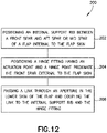
- a method of reducing an external footprint of a support structure for pivotally mounting a flap to a trailing edge of an aircraft wing as defined in claim 13 is disclosed.
- the method provides for a smaller external footprint of the support structure attached to the undersurface of the flap and permits use of a fairing having a narrow cross-sectional area.
- an internal support rib of the support structure is positioned between the spars of the flap internal to the flap skin.
- a hinge fitting exhibiting an actuation point and a hinge point is positioned proximate the front spar external to the flap skin.
- a link is passed through an aperture in the lower skin of the flap and coupled to the internal support rib and the hinge fitting, such that the bulk of the support structure is internal to the flap, and the external components of the support structure have a small external footprint.
- flap hinge assembly various examples are described with reference to aerospace structures, and more particularly to swept-wing aircraft of the type shown for example in FIGS. 1A and 1B , to illustrate the general principles of the present disclosure.
- FIGS. 1A and 1B is generally representative of wings used for commercial passenger aircraft
- teachings of this disclosure may be applied to other passenger aircraft, cargo aircraft, military aircraft, rotorcraft, and other types of aircraft or aerial vehicles, as well as aerospace vehicles, satellites, space launch vehicles, rockets, and other aerospace vehicles, as well as boats and other watercraft, trains, automobiles, trucks, buses, or other suitable structures having surfaces that move relative to one another under a load.
- those methods, procedures, components, or functions which are commonly known to persons of ordinary skill in the field of the disclosure are not described in detail herein.
- FIGS. 1A and 1B illustrate partial top and rear views, respectively, of an exemplary aircraft 10 having a fuselage 12, a wing 14, and an under-wing mounted engine 16.
- the wing 14 is of a type having a swept-wing structure, wherein a wing axis (shown by dotted line A in FIG. 1A ) of the wing 14 forms an acute angle C with respect to a lengthwise axis (shown by dotted line B) of the fuselage 12.
- the wing 14 has a plurality of trailing edge flaps 17, including inboard flap 18 and one or more outboard flap(s) 20, all moveably mounted to the wing fixed trailing edge 22.
- the flaps 17 are supported by and moveable with respect to the wing fixed trailing edge 22 by multiple flap support structure (not shown in FIGS. 1A and IB), each of which are covered with an aerodynamic fairing 24 to minimize drag during flight.
- the fairing 24 is attached to undersurfaces of the wing 14 and the flaps 17.
- the flap support structures are positioned on the undersurface of the flaps 17, in whole or in part, generally normal to the wing axis A of the wing 14.
- the fairings are preferably positioned in a streamwise direction generally parallel to the lengthwise axis B of the fuselage 12 and, for the outboard flaps 20, at the acute angle C (not normal) relative to the wing axis A of the wing 14. Therefore, at least for the outboard flaps 20, the fairings 24 must be wide enough to cover an angled width of the flap support structure.
- the disclosed flap hinge assembly 30 is an improved type of flap support structure that has a smaller attachment footprint 32 (i.e., smaller area on the undersurface of the flaps 17), permitting the aerodynamic fairing 24 to have a smaller cross-sectional area 26, which further minimizes drag during flight and increases overall aircraft efficiency.
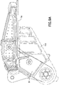
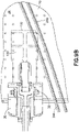
- FIGS. 9A and 9B are illustrations showing the smaller attachment footprint 32 of the flap hinge assembly 30 to the undersurface 34 of an outboard flap 20 as compared, for example, to the larger footprint 102 of a standard straight hinge fitting type of flap support structure 100 (a standard straight hinge fitting) on an outboard flap 20 of a Boeing 787-9 aircraft ( FIG. 9A shows a view looking inboard along the hingeline; FIG. 9B shows a view looking up on the undersurface 34 of outboard flap 20).
- Fairing edges 24A and 24B of two fairings 24 are depicted to illustrate the corresponding size difference of the fairings 24.
- the fairing used with the flap hinge assembly 30 of this disclosure has a narrower cross-section than the fairing used with the flap support structure 100, which must be wider to accommodate the larger footprint 102 of the typical flap support structure 100 (fairing edge 24A is closer than fairing edge 24B to the flap hinge assembly 30). This permits the fairing 24 used with the flap hinge assembly 30 to have a smaller cross-sectional area 26 with reduced drag and improved aerodynamics.
- the flap hinge assembly 30 has particular application on outboard flaps 20 where the acute angle C is formed by the fairings 24 relative to the wing axis A of the wing 14. However, the flap hinge assembly 30 may also replace a typical support structure for the inboard flap 18, which is generally positioned to be parallel to the streamwise direction and the lengthwise axis B of the fuselage 12.
- the flap hinge assembly 30 moveably connects one of the flaps 17 to a wing fixed trailing edge 22 of a wing 14.
- the drawings refer to an outboard flap 20, but the concepts are the same for an inboard flap 18 or other types of aerospace structures.
- the trailing edge 22 of the wing 14 is typically equipped with a wing hinge structure 36 extending aft from the trailing edge 22 below the wing lower skin 38 and terminating with a pair of spaced-apart pivot lugs 40 at a distal end of the trailing edge hinge structure 36 for connection to the outboard flap 20.
- the flap hinge assembly 30 has a hinge fitting 44 extending below a flap lower skin 46 and typically forward of a forward edge 48 of the outboard flap 20.
- the hinge fitting 44 has an actuation point 50 proximate an upper end of the hinge fitting 44 and a flap hinge point 52 proximate a lower end of the hinge fitting 44, both positioned forward of the forward edge 48 of the outboard flap 20.
- the spaced-apart pivot lugs 40 of the wing hinge structure 36 of the wing 14 are pivotally connected to the flap hinge point 52 via any type of pivoting pin through aligned holes 42 in both the spaced-apart pivot lugs 40 and the flap hinge point 52.
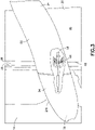
- a space 58 is provided between trailing edge 22 of the wing 14 and the forward edge 48 of the outboard flap 20.
- An aerodynamic fairing 24 is attached at its edges 24A to the undersurface 34 of the outboard flap 20 to cover the wing hinge structure 36 and the hinge fitting 44 of the outboard flap 20.
- the aerodynamic fairing 24 may be comprised of a front fairing 54 attached to the wing 14 and an aft fairing 56 attached to the outboard flap 20 to facilitate relative movement of the outboard flap 20 in relation to the wing 14.
- the fairing 24 is attached to the wing 14 and the outboard flap 20 at an angle relative to the flap hinge assembly 30 and the trailing edge 22 of the wing 14 to position the fairing 24 in a streamwise direction.
- the small footprint 32 of the flap hinge assembly 30 permits the fairing 24 to have a narrow cross-sectional area 26 in this configuration to minimize drag and improve aerodynamic efficiencies.
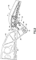
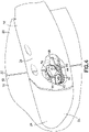
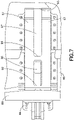
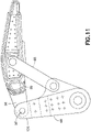
- the flap hinge assembly 30 for pivotally mounting flaps 17 to the trailing edge 22 of an aircraft wing 14 is shown in further detail in FIGS 5 - 8 .
- the inboard flap 18 and outboard flap 20 are of the type having a flap box structure comprising a front spar 60, an aft spar 62 and a plurality of ribs connecting the front spar 60 and aft spar 62.
- a flap skin 64 surrounds the flap box structure to enclose the front spar 60, an aft spar 62 and the plurality of ribs.
- An internal support rib 66 is positioned between the front spar 60 and either the aft spar 62 or a mid spar 74 of the flap box structure internal to the flap skin 64 to provide structural support to the hinge fitting 44, which is positioned proximate the front spar 60 of the flap box structure external to the skin 64.
- a link 68 passes through an aperture 70 in a lower skin 46 of the flap skin 64 and couples the internal support rib 66 to the hinge fitting 44.
- the internal support rib 66 and the hinge fitting 44 may each be composed of a primary and secondary parts to provide alternative load paths in structures as is typical in the art. As shown in FIG.
- the internal support rib 66 is composed of a primary rib 66A and two secondary ribs 66B positioned on the sides of the primary rib 66A; and the hinge fitting 44 is composed of a primary fitting 44A and two secondary fittings 44B positioned on the sides of the primary fitting 44A.
- the internal support rib 66 is attached to the flap lower skin 46 with fasteners 47, which may be any type of fastener suitable for aerospace applications.
- the internal support rib 66 or as shown the secondary ribs 66B, includes a mid spar attachment point 72 on a side of the internal support rib 66 for attaching the mid spar 74 within the flap box structure.
- the mid spar 74 is positioned to be generally parallel to and between the front spar 60 and the aft spar 62.
- the hinge fitting 44 is positioned to extend external to the lower skin 46 a chordwise distance from the front spar 60 that is less than a distance between the front spar 60 and the mid spar 74. This small chordwise distance contributes to the smaller attachment footprint 32 of the flap hinge assembly 30 on the undersurface 34 of the flaps 17.
- the hinge fitting 44 has a generally horizontal load transfer face 76 and a generally vertical load transfer face 78 positioned respectively about a lower generally horizontal flange 80 of the front spar 60 and a generally vertical web 82 of the front spar 60.
- the generally horizontal load transfer face 76 of the hinge fitting 44 has a first length that is approximately equal to a second length of the lower generally horizontal flange 80 of the front spar 60
- the generally vertical load transfer face 78 of the hinge fitting 44 has a third length that is approximately equal to a fourth length of the generally vertical web 82 of the front spar 60.
- the generally horizontal load transfer face 76 and the vertical load transfer face 78 typically transfer load via compression contact with the flap box (rather than tension), which further enhances the load transfer properties of the flap hinge assembly 30.
- the link 68 that connects the hinge fitting 44 to the internal support rib 66 comprises a generally elongated structure having a first hole 84 and a second hole 86 at respective ends of the link 68.
- the link 68 may be formed as a unitary structure or may be formed with a primary link 68A and a secondary link 68B in back to back configuration as shown in FIG. 5 .
- the first hole 84 and the second hole 86 of the link 68 are coupled to the internal support rib 66 and the hinge fitting 44 via any type of pin joint 89 known in the art, for example, a pin-in-pin joint acting in double shear (held on both sides of the pin).
- the internal support rib 66 comprises a link attachment point 88 positioned proximate the mid spar attachment point 72, and between the front spar 60 and the mid spar 74, for coupling the first hole 84 of the link 68 to the internal support rib 66.
- the link attachment point 88 may be formed by structuring the internal support rib 66 with two spaced-apart chordwise webs 67 connected together at a front region 92, a mid region 94 and an aft region 96 to form spaces 97 between the two chordwise webs 67.
- the link 68 is coupled in one of the spaces 97 formed between the front region 92 and the mid region 94.
- the hinge fitting 44 comprises a connection flange 90 for coupling the second hole 86 of the link 68 to the hinge fitting 44.
- the connection flange 90 is positioned between the hinge point 52 and the generally horizontal load transfer face 76 of the hinge fitting 44.
- the hinge fitting 44 When the hinge fitting 44 is connected to the internal support rib 66 through the link 68, the first hole 84 and the second hole 86 of the link 68 and the hinge point 52 in the hinge fitting 44 are aligned in a substantially straight line D, shown in FIG. 2 .
- the straight line D forms an aft angle E relative to the lower skin that is greater than 90 degrees and less than about 135 degrees to further provide the smaller attachment footprint 32.
- the foregoing structural features all contribute to the smaller attachment footprint 32 of the flap hinge assembly 30.
- the volume of the external structure of the flap hinge assembly 30 (including the hinge fitting 44 and part of the link 68 is about 2000 cubic centimeters (120 cubic inches), which is substantially less the external structure volume of a kinked or cranked design (about 4100 cubic centimeters (250 cubic inches)) or a straight hinge (about 2400 cubic centimeters (150 cubic inches)), resulting in the ability to use a fairing 24 that has a width of 53 centimeters (21 inches), which is approximately 15% reduced as compared to a width of the fairing required for a typical straight hinge, and therefore a reduced cross-sectional area 26.
- This smaller attachment footprint 32 also results in a weight reduction for each flap hinge assembly 30 of about 21% as compared to the weight of a kinked or cranked design (about 20 kilograms (43 pounds) as compared to about 24 kilograms (52 pounds)), and about 64 kilograms (140 pounds) reduction for an aircraft of a size similar to the Boeing 777.
- the design of a the flap hinge assembly also offers a determinant load path, which simplifies structural analysis through reduced reliance on FEM for internal load calculations, provides a corresponding reduction in non-recurring analysis costs, and provides a weight savings when compared to existing designs.
- the flap hinge assembly 30 provides for a more efficient load transfer through shear joints at the connection flange 90 in the hinge fitting 44 and the link attachment point 88 in the internal support rib 66, and compression joints at the generally horizontal load transfer face 76 and the vertical load transfer face 78 of the hinge fitting 44, instead of numerous tension joints typically used to connect straight or cranked hinges to the undersurface 34 of the flaps 17, and avoids use of heavier and inefficient "bathtub" type tension joints.
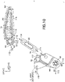
- FIG. 10 is an exploded side view of the flap hinge assembly 30 showing the efficient load paths through the hinge fitting 44, the link 68 and the internal support rib 66, including flap attachment interface loads 110, compression loads 112, tension load 114 through the link 68 and shear load 116 around the internal support rib 66.
- flap attachment interface loads 110 under typical air loading, the flap-hinge moment is reacted as a couple between the link 68 (tension load) and the generally horizontal load transfer face 76 and the vertical load transfer face 78, which contact the lower horizontal flange 80 and vertical web 82 of the front spar 60, where the compression load 112 results.
- the primary load (CX) of the flap attachment interface load 110 is applied at the actuation point 50 and acts in the x direction.
- This load is reacted as horizontal compression load (FX) applied against the vertical load transfer face 78, which is in contact with the vertical web 82 of the front spar 60.
- a vertical compression load (FZ) exists at the generally horizontal load transfer face 76 where compression occurs through a forward region of the flap lower skin 46 to the internal support rib 66. Loading through the link 68 is in tension (under normal operation) where it is reacted at each end of the link 68 through a standard pin, lug and clevis double shear arrangement.
- shear load 116 resulting from the attachment of the link 68 and compression loads 112 to the internal support rib 66 acts on the internal support rib 66 and is reacted at the connections of between the front spar 60, the aft spar 62 and the mid spar 74 as a running load (shear flow).
- This shear flow reaction is typical of airplane multi-cell support rib reaction loading.
- the reduced attachment footprint 32 of the hinge fitting 44 will also result in alleviation of load caused by a strain mismatch between the materials of the flap hinge assembly 30 and the flap box (e.g., front spar 60, aft spar 62 and mid spar 74) when subject to a non room temperature thermal environment. For example, under elevated or reduced temperatures, thermal loading is setup between aluminum materials of the flap hinge assembly 30 and carbon fiber materials of the flap skins 64. The reduced attachment footprint 32 would also alleviate these undesirable thermal loads.
- a detectable failure feature for the link 68 may be incorporated to annunciate a failure of the link 68 to the pilot through existing skew detection systems. This would permit the link 68 to be designed as a unitary structure with a single load path instead of having primary and secondary load paths since it would then be detectable through twisting of the flap box.
- the upper portion 120 of the hinge fitting 44 where the actuation point 50 is located may be formed integral with the internal support rib 66 and the front spar 60 may be separated into two parts to attach on both sides of the internal support rib 66 to accommodate this.
- a further aspect of the disclosure relates to a method of reducing an external footprint 32 of a support structure for pivotally mounting a flap 17 to a trailing edge 22 of an aircraft wing 14, where the flap 17 has a front spar 60, an aft spar 62 and a plurality of ribs connecting the front spar 60 and the aft spar 62, and a flap skin 64 surrounding the front spar 60, the aft spar 62 and the plurality of ribs.
- an internal support rib 66 is positioned between the front spar 60 and the aft spar 62 of the flap 17 internal to the flap skin 64.
- a hinge fitting 44 having an actuation point 50 and a hinge point 52 is positioned proximate the front spar 60 external to the flap skin 64.
- a link 68 is passed through an aperture 70 in the lower skin 46 of the flap 17 and coupled to the internal support rib 66 and the hinge fitting 44, such that the bulk of the support structure is internal to the flap 17, and the external components of the support structure have a small external footprint 32.
- the flap hinge assembly 30 may be used with existing wing trailing edge connection structures in the Boeing 787 and new 777-8/9 aircraft or any other aircraft having a suitable structural beam extending below the wing lower skin 38, or the flap hinge point 52 may be readily modified to connect with other types of wing trailing edge connection structures.
- the flap hinge assembly 30 may also be used with any type of flap box structure comprising multiple spars, a plurality of ribs connecting between spars, and a skin surrounding the flap box structure.
- the internal support rib 66 of the flap hinge assembly 30 may be positioned between the front spar 60 and either an aft spar 62 or mid spar 74 of the flap box structure internal to the flap skin 64 taking into account flap size and design considerations. It is intended that all such modifications and variations be considered as within the scope of the following claims.
Landscapes
- Engineering & Computer Science (AREA)
- Aviation & Aerospace Engineering (AREA)
- General Engineering & Computer Science (AREA)
- Mechanical Engineering (AREA)
- Tires In General (AREA)
- Connection Of Plates (AREA)
Claims (13)
- Kombination aus einer Klappe (17) und einer Klappenscharnieranordnung (30) zum schwenkbaren Anbringen einer Klappe (17) an einer Hinterkante (22) eines Flugzeugflügels (14),wobei die Klappe eine Klappenkastenstruktur mit einer Vielzahl von Holmen (60, 62, 74), einer Vielzahl von Rippen, die zwischen den Holme verbunden sind, und einer Haut (64), die die Holme und die Rippen umgibt, aufweist, wobei die Haut (64) eine untere Haut (46) umfasst, undwobei die Klappenscharnieranordnung Folgendes umfasst:eine innere Stützrippe (66), die innerhalb der Haut zwischen den Holmen der Klappenkastenstruktur positioniert ist,einen Scharnierbeschlag (44) mit einem Betätigungspunkt (50) und einem Scharnierpunkt (52), wobei der Scharnierbeschlag außerhalb der Haut in der Nähe eines vorderen Holms (60) positioniert ist, undein Verbindungsglied (68), das durch eine Öffnung (70) in der unteren Haut (46) der Klappe verläuft und die innere Stützrippe mit dem Scharnierbeschlag koppelt.
- Kombination nach Anspruch 1, wobei sich der Scharnierbeschlag (44) außerhalb der unteren Haut (46) von dem vorderen Holm (60) erstreckt in einem Sehnenabstand, der kleiner ist als ein Abstand zwischen dem vorderen Holm und einem mittleren Holm (74) der Klappe (17).
- Kombination nach Anspruch 1 oder 2, wobei der Scharnierbeschlag (44) ferner eine im Allgemeinen horizontale Lastübertragungsfläche (76) und eine im Allgemeinen vertikale Lastübertragungsfläche (78) umfasst, die jeweils um einen im Allgemeinen horizontalen Flansch (80) des vorderen Holms (60) bzw. einen im Allgemeinen vertikalen Steg (82) des vorderen Holms positioniert sind.
- Kombination nach Anspruch 3, wobei die im Allgemeinen horizontale Lastübertragungsfläche (76) des Scharnierbeschlags (44) eine erste Länge aufweist, die ungefähr gleich einer zweiten Länge des im Allgemeinen horizontalen Flansches (80) des vorderen Holms (60) ist, und die im Allgemeinen vertikale Lastübertragungsfläche (78) des Scharnierbeschlags eine dritte Länge aufweist, die ungefähr gleich einer vierten Länge des im Allgemeinen vertikalen Stegs (82) des vorderen Holms ist.
- Kombination nach einem der vorhergehenden Ansprüche, wobei das Verbindungsglied (68) eine im Allgemeinen längliche Struktur mit einem ersten Loch (84) und einem zweiten Loch (86) an jeweiligen Enden des Verbindungsglieds umfasst, wobei das erste Loch und das zweite Loch jeweils über doppelschnittig wirkende Bolzengelenke (89) mit der inneren Stützrippe (66) bzw. dem Scharnierbeschlag (44) gekoppelt sind.
- Kombination nach Anspruch 5, wobei die innere Stützrippe (66) einen Verbindungsgliedbefestigungspunkt (88) umfasst, der in der Nähe eines mittleren Holms (74) der Klappe (17) positioniert ist, um das erste Loch (84) des Verbindungsglieds (68) mit der inneren Stützrippe zu koppeln.
- Kombination nach Anspruch 5 oder 6, wobei der Scharnierbeschlag (44) ferner einen Verbindungsflansch (90) zum Koppeln des zweiten Lochs (86) des Verbindungsglieds (68) mit dem Scharnierbeschlag umfasst, wobei der Verbindungsflansch zwischen dem Scharnierpunkt (52) und einer im Allgemeinen horizontalen Lastübertragungsfläche (76) des Scharnierbeschlags positioniert ist.
- Kombination nach Anspruch 7, wobei das erste Loch (84), das zweite Loch (86) und der Scharnierpunkt (52) in einer im Wesentlichen geraden Linie (D) ausgerichtet sind.
- Kombination nach Anspruch 8, wobei die im Wesentlichen gerade Linie (D) in Relation zu der unteren Haut (46) einen hinteren Winkel (E) bildet, der größer als 90 Grad ist.
- Kombination nach Anspruch 6, wobei der Verbindungsbefestigungspunkt (88) zwischen dem vorderen Holm (60) und dem mittleren Holm (74) der Klappe (17) positioniert ist.
- Kombination nach Anspruch 6 oder 10, wobei die innere Stützrippe (66) zwei Stege (67) umfasst, die an einem vorderen Bereich (92), einem mittleren Bereich (94) und einem hinteren Bereich (96) der inneren Stützrippe miteinander verbunden sind, um Zwischenräume (97) zwischen den beiden Stegen zu bilden, wobei das Verbindungsglied (68) in einem der zwischen dem vorderen Bereich und dem mittleren Bereich gebildeten Zwischenräume gekoppelt ist.
- Kombination nach einem der vorhergehenden Ansprüche, wobei die innere Stützrippe (66), der Scharnierbeschlag (44) und das Verbindungsglied (68) so angeordnet sind, dass sie einen bestimmenden Lastpfad für auf die Klappe (17) wirkende Luftlasten bereitstellen.
- Verfahren zum Reduzieren einer äußeren Grundfläche (32) einer Stützstruktur zum schwenkbaren Anbringen einer Klappe (17) an einer Hinterkante (22) eines Flügels (14) eines Flugzeugs (10), wobei die Klappe eine Klappenkastenstruktur mit Holmen und Rippen, die die Holme verbinden, und eine Klappenhaut (64), die die Holme und die Rippen umgibt, umfasst, wobei die Haut (64) eine untere Haut (46) umfasst, wobei das Verfahren die folgenden Schritte umfasst:Positionieren einer inneren Stützrippe (66) innerhalb der Klappenhaut zwischen den Holmen der Klappe;Positionieren eines Scharnierbeschlags (44) mit einem Betätigungspunkt (50) und einem Scharnierpunkt (52) außerhalb der Klappenhaut in der Nähe eines vorderen Holms (60);Führen eines Verbindungsglieds (68) durch eine Öffnung (70) in der unteren Haut (46) der Klappe; undKoppeln des Verbindungsglieds mit der inneren Stützrippe und dem Scharnierbeschlag.
Applications Claiming Priority (1)
| Application Number | Priority Date | Filing Date | Title |
|---|---|---|---|
| US15/356,693 US10494083B2 (en) | 2016-11-21 | 2016-11-21 | Aircraft flap hinge |
Publications (2)
| Publication Number | Publication Date |
|---|---|
| EP3323712A1 EP3323712A1 (de) | 2018-05-23 |
| EP3323712B1 true EP3323712B1 (de) | 2023-01-04 |
Family
ID=60409239
Family Applications (1)
| Application Number | Title | Priority Date | Filing Date |
|---|---|---|---|
| EP17202633.8A Active EP3323712B1 (de) | 2016-11-21 | 2017-11-20 | Flugzeugklappenscharnier |
Country Status (4)
| Country | Link |
|---|---|
| US (1) | US10494083B2 (de) |
| EP (1) | EP3323712B1 (de) |
| JP (1) | JP6917258B2 (de) |
| CN (1) | CN108082450B (de) |
Families Citing this family (18)
| Publication number | Priority date | Publication date | Assignee | Title |
|---|---|---|---|---|
| US10493083B2 (en) * | 2015-10-30 | 2019-12-03 | Cmp Development Llc | Spironolactone aqueous compositions |
| CN109606638B (zh) * | 2018-11-07 | 2022-05-27 | 中国航空工业集团公司西安飞机设计研究所 | 一种下沉铰链式襟翼摇臂支撑结构 |
| US11167840B2 (en) * | 2019-04-16 | 2021-11-09 | The Boeing Company | Aircraft main landing gear drag brace backup fitting assemblies and related methods |
| US11492097B2 (en) * | 2019-08-30 | 2022-11-08 | Airbus Operations Gmbh | Wing and aircraft |
| US11046420B2 (en) * | 2019-10-23 | 2021-06-29 | The Boeing Company | Trailing edge flap having a waffle grid interior structure |
| US11338905B2 (en) * | 2019-11-11 | 2022-05-24 | The Boeing Company | Offset drive arm actuation of inboard flaps |
| CN111056041B (zh) * | 2019-12-25 | 2022-10-11 | 中国航空工业集团公司西安飞机设计研究所 | 一种襟翼咔滞的处理方法 |
| US11104422B1 (en) | 2020-02-07 | 2021-08-31 | The Boeing Company | Compact and redundant method for powering flight control surface from within fuselage |
| US11247767B2 (en) * | 2020-03-05 | 2022-02-15 | Ruben Leon | Wireless autopilot system |
| US11933353B2 (en) * | 2021-03-16 | 2024-03-19 | The Boeing Company | Three piece failsafe clevis |
| EP4105119B1 (de) | 2021-06-18 | 2023-09-06 | Airbus Operations GmbH | Befestigungskonzept für eine verkleidung an einem tragflügel wie einer klappe oder einem flügel eines flugzeugs |
| CN114104261B (zh) * | 2022-01-24 | 2022-04-12 | 中国空气动力研究与发展中心空天技术研究所 | 一种复合翼飞行器的机翼翼梁 |
| US11827338B2 (en) | 2022-02-14 | 2023-11-28 | Rohr, Inc. | Aircraft control surface with linear actuator |
| EP4282751B1 (de) * | 2022-05-24 | 2025-08-27 | Airbus Operations GmbH | Lasteinführungssystem und verfahren zur herstellung eines lasteinführungssystems |
| EP4385888B1 (de) * | 2022-12-14 | 2026-02-18 | Airbus Operations GmbH | Lasteinführungssystem und verfahren zur herstellung eines lasteinführungssystems |
| EP4385887B1 (de) | 2022-12-14 | 2026-02-18 | Airbus Operations GmbH | Lasteinführungssystem und verfahren zur herstellung eines lasteinführungssystems |
| US12494735B2 (en) | 2023-10-10 | 2025-12-09 | Xplore Inc. | Hinge-locking mechanism for deployable solar array |
| CN119190340B (zh) * | 2024-10-21 | 2025-10-28 | 南京航空航天大学 | 一种用于产生机翼扭转的驱动装置 |
Family Cites Families (23)
| Publication number | Priority date | Publication date | Assignee | Title |
|---|---|---|---|---|
| DE2037933A1 (de) | 1970-07-30 | 1972-02-03 | Mitsubishi Jukogyo K.K., Tokio | Flugzeug-Tragflügel |
| US3790106A (en) * | 1973-01-24 | 1974-02-05 | J Morris | Flap system |
| US3853289A (en) | 1973-02-15 | 1974-12-10 | Boeing Co | Trailing edge flap and actuating mechanism therefor |
| US3985319A (en) | 1975-02-03 | 1976-10-12 | The Boeing Company | Variable pivot trailing edge flap |
| US4434959A (en) | 1981-09-28 | 1984-03-06 | The Boeing Company | Airfoil flap assembly with flap track member |
| US4448375A (en) | 1982-09-29 | 1984-05-15 | The Boeing Company | Folding truss mechanism for trailing edge flaps |
| US4605187A (en) | 1984-03-09 | 1986-08-12 | The Boeing Company | Wing flap mechanism |
| US4702442A (en) | 1984-12-06 | 1987-10-27 | The Boeing Company | Aircraft trailing edge flap apparatus |
| US4669687A (en) | 1985-03-06 | 1987-06-02 | The Boeing Company | Airfoil flap member with flap track member |
| FR2591557B1 (fr) * | 1985-12-13 | 1988-03-25 | Aerospatiale | Systeme de couplage de deux volets d'une aile d'aeronef, et aile d'aeronef equipee d'un tel systeme |
| US4995575A (en) | 1988-09-26 | 1991-02-26 | The Boeing Company | Wing trailing edge flap mechanism |
| US5161757A (en) | 1989-07-31 | 1992-11-10 | The Boeing Company | Extending bent shaft flap drive |
| GB2260521B (en) * | 1991-10-19 | 1995-03-22 | British Aerospace | An aircraft wing leading edge arrangement |
| US5915653A (en) | 1996-01-02 | 1999-06-29 | The Boeing Company | Spherical mating fairings for hingeline applications |
| US7500641B2 (en) * | 2005-08-10 | 2009-03-10 | The Boeing Company | Aerospace vehicle flow body systems and associated methods |
| US7762500B1 (en) * | 2006-11-06 | 2010-07-27 | Sanjay Dhall | Telescopic wing with articulated structural spar |
| US8763953B2 (en) | 2010-07-14 | 2014-07-01 | The Boeing Company | Aircraft flap actuator assembly |
| US8684316B2 (en) * | 2011-09-23 | 2014-04-01 | The Boeing Company | Aircraft flap mechanism having compact large fowler motion providing multiple cruise positions |
| GB201117340D0 (en) * | 2011-10-07 | 2011-11-23 | Airbus Uk Ltd | Flat support |
| EP2805879B1 (de) * | 2013-05-22 | 2017-07-05 | Airbus Operations GmbH | Klappenanordnung für einen flügel eines flugzeugs und ein flugzeug mit einem flügel mit solch einer klappenanordnung |
| US9878774B2 (en) | 2014-09-19 | 2018-01-30 | The Boeing Company | System and method for operating a droop panel using a pin joint linkage assembly |
| JP2016078584A (ja) * | 2014-10-15 | 2016-05-16 | 三菱航空機株式会社 | 航空機 |
| US9840320B2 (en) | 2014-12-19 | 2017-12-12 | The Boeing Company | Trailing edge device with bell crank mechanism |
-
2016
- 2016-11-21 US US15/356,693 patent/US10494083B2/en active Active
-
2017
- 2017-09-25 JP JP2017183420A patent/JP6917258B2/ja active Active
- 2017-11-20 EP EP17202633.8A patent/EP3323712B1/de active Active
- 2017-11-20 CN CN201711160861.6A patent/CN108082450B/zh active Active
Also Published As
| Publication number | Publication date |
|---|---|
| CN108082450A (zh) | 2018-05-29 |
| JP2018095237A (ja) | 2018-06-21 |
| CN108082450B (zh) | 2022-10-11 |
| US10494083B2 (en) | 2019-12-03 |
| JP6917258B2 (ja) | 2021-08-11 |
| EP3323712A1 (de) | 2018-05-23 |
| US20180141636A1 (en) | 2018-05-24 |
Similar Documents
| Publication | Publication Date | Title |
|---|---|---|
| EP3323712B1 (de) | Flugzeugklappenscharnier | |
| CA3035269C (en) | Wing flap with torque member and method for forming thereof | |
| US8302908B1 (en) | Blended wing aircraft | |
| JP7407589B2 (ja) | 折り曲げ可能航空機翼 | |
| US8720817B1 (en) | Twin-boom empennage | |
| US10597141B2 (en) | Wing flap with torque member and method for forming thereof | |
| US9878774B2 (en) | System and method for operating a droop panel using a pin joint linkage assembly | |
| EP3546344B1 (de) | Flügelklappe mit drehmomentelement und verfahren zur formung davon | |
| US8061655B1 (en) | Aircraft configuration utilizing fuselage, wing, empennage, and exhaust flow control devices | |
| CN108698684A (zh) | 用于翼面的边缘变形装置 | |
| US8231079B2 (en) | Aerodynamic braking device for aircraft | |
| US8567711B1 (en) | Swept-wing powered-lift aircraft | |
| US8167249B1 (en) | Controllable upper surface blown nozzle | |
| US12434811B2 (en) | Flap support systems and methods for a wing of an aircraft | |
| CN117125245A (zh) | 用于飞行器的机翼组件和飞行器 | |
| GB2632284A (en) | Flight control surface deployment |
Legal Events
| Date | Code | Title | Description |
|---|---|---|---|
| PUAI | Public reference made under article 153(3) epc to a published international application that has entered the european phase |
Free format text: ORIGINAL CODE: 0009012 |
|
| STAA | Information on the status of an ep patent application or granted ep patent |
Free format text: STATUS: REQUEST FOR EXAMINATION WAS MADE |
|
| 17P | Request for examination filed |
Effective date: 20171120 |
|
| AK | Designated contracting states |
Kind code of ref document: A1 Designated state(s): AL AT BE BG CH CY CZ DE DK EE ES FI FR GB GR HR HU IE IS IT LI LT LU LV MC MK MT NL NO PL PT RO RS SE SI SK SM TR |
|
| AX | Request for extension of the european patent |
Extension state: BA ME |
|
| STAA | Information on the status of an ep patent application or granted ep patent |
Free format text: STATUS: EXAMINATION IS IN PROGRESS |
|
| 17Q | First examination report despatched |
Effective date: 20190911 |
|
| RIC1 | Information provided on ipc code assigned before grant |
Ipc: B64C 9/18 20060101ALN20210204BHEP Ipc: B64C 9/02 20060101AFI20210204BHEP |
|
| GRAP | Despatch of communication of intention to grant a patent |
Free format text: ORIGINAL CODE: EPIDOSNIGR1 |
|
| STAA | Information on the status of an ep patent application or granted ep patent |
Free format text: STATUS: GRANT OF PATENT IS INTENDED |
|
| RIC1 | Information provided on ipc code assigned before grant |
Ipc: B64C 9/18 20060101ALN20220615BHEP Ipc: B64C 9/02 20060101AFI20220615BHEP |
|
| RIC1 | Information provided on ipc code assigned before grant |
Ipc: B64C 9/18 20060101ALN20220629BHEP Ipc: B64C 9/02 20060101AFI20220629BHEP |
|
| INTG | Intention to grant announced |
Effective date: 20220720 |
|
| GRAS | Grant fee paid |
Free format text: ORIGINAL CODE: EPIDOSNIGR3 |
|
| GRAA | (expected) grant |
Free format text: ORIGINAL CODE: 0009210 |
|
| STAA | Information on the status of an ep patent application or granted ep patent |
Free format text: STATUS: THE PATENT HAS BEEN GRANTED |
|
| AK | Designated contracting states |
Kind code of ref document: B1 Designated state(s): AL AT BE BG CH CY CZ DE DK EE ES FI FR GB GR HR HU IE IS IT LI LT LU LV MC MK MT NL NO PL PT RO RS SE SI SK SM TR |
|
| REG | Reference to a national code |
Ref country code: GB Ref legal event code: FG4D |
|
| REG | Reference to a national code |
Ref country code: CH Ref legal event code: EP |
|
| REG | Reference to a national code |
Ref country code: AT Ref legal event code: REF Ref document number: 1541774 Country of ref document: AT Kind code of ref document: T Effective date: 20230115 |
|
| REG | Reference to a national code |
Ref country code: DE Ref legal event code: R096 Ref document number: 602017065174 Country of ref document: DE |
|
| REG | Reference to a national code |
Ref country code: IE Ref legal event code: FG4D |
|
| RAP4 | Party data changed (patent owner data changed or rights of a patent transferred) |
Owner name: THE BOEING COMPANY |
|
| REG | Reference to a national code |
Ref country code: LT Ref legal event code: MG9D |
|
| REG | Reference to a national code |
Ref country code: NL Ref legal event code: MP Effective date: 20230104 |
|
| REG | Reference to a national code |
Ref country code: AT Ref legal event code: MK05 Ref document number: 1541774 Country of ref document: AT Kind code of ref document: T Effective date: 20230104 |
|
| P01 | Opt-out of the competence of the unified patent court (upc) registered |
Effective date: 20230516 |
|
| PG25 | Lapsed in a contracting state [announced via postgrant information from national office to epo] |
Ref country code: NL Free format text: LAPSE BECAUSE OF FAILURE TO SUBMIT A TRANSLATION OF THE DESCRIPTION OR TO PAY THE FEE WITHIN THE PRESCRIBED TIME-LIMIT Effective date: 20230104 |
|
| PG25 | Lapsed in a contracting state [announced via postgrant information from national office to epo] |
Ref country code: RS Free format text: LAPSE BECAUSE OF FAILURE TO SUBMIT A TRANSLATION OF THE DESCRIPTION OR TO PAY THE FEE WITHIN THE PRESCRIBED TIME-LIMIT Effective date: 20230104 Ref country code: PT Free format text: LAPSE BECAUSE OF FAILURE TO SUBMIT A TRANSLATION OF THE DESCRIPTION OR TO PAY THE FEE WITHIN THE PRESCRIBED TIME-LIMIT Effective date: 20230504 Ref country code: NO Free format text: LAPSE BECAUSE OF FAILURE TO SUBMIT A TRANSLATION OF THE DESCRIPTION OR TO PAY THE FEE WITHIN THE PRESCRIBED TIME-LIMIT Effective date: 20230404 Ref country code: LV Free format text: LAPSE BECAUSE OF FAILURE TO SUBMIT A TRANSLATION OF THE DESCRIPTION OR TO PAY THE FEE WITHIN THE PRESCRIBED TIME-LIMIT Effective date: 20230104 Ref country code: LT Free format text: LAPSE BECAUSE OF FAILURE TO SUBMIT A TRANSLATION OF THE DESCRIPTION OR TO PAY THE FEE WITHIN THE PRESCRIBED TIME-LIMIT Effective date: 20230104 Ref country code: HR Free format text: LAPSE BECAUSE OF FAILURE TO SUBMIT A TRANSLATION OF THE DESCRIPTION OR TO PAY THE FEE WITHIN THE PRESCRIBED TIME-LIMIT Effective date: 20230104 Ref country code: ES Free format text: LAPSE BECAUSE OF FAILURE TO SUBMIT A TRANSLATION OF THE DESCRIPTION OR TO PAY THE FEE WITHIN THE PRESCRIBED TIME-LIMIT Effective date: 20230104 Ref country code: AT Free format text: LAPSE BECAUSE OF FAILURE TO SUBMIT A TRANSLATION OF THE DESCRIPTION OR TO PAY THE FEE WITHIN THE PRESCRIBED TIME-LIMIT Effective date: 20230104 |
|
| PG25 | Lapsed in a contracting state [announced via postgrant information from national office to epo] |
Ref country code: SE Free format text: LAPSE BECAUSE OF FAILURE TO SUBMIT A TRANSLATION OF THE DESCRIPTION OR TO PAY THE FEE WITHIN THE PRESCRIBED TIME-LIMIT Effective date: 20230104 Ref country code: PL Free format text: LAPSE BECAUSE OF FAILURE TO SUBMIT A TRANSLATION OF THE DESCRIPTION OR TO PAY THE FEE WITHIN THE PRESCRIBED TIME-LIMIT Effective date: 20230104 Ref country code: IS Free format text: LAPSE BECAUSE OF FAILURE TO SUBMIT A TRANSLATION OF THE DESCRIPTION OR TO PAY THE FEE WITHIN THE PRESCRIBED TIME-LIMIT Effective date: 20230504 Ref country code: GR Free format text: LAPSE BECAUSE OF FAILURE TO SUBMIT A TRANSLATION OF THE DESCRIPTION OR TO PAY THE FEE WITHIN THE PRESCRIBED TIME-LIMIT Effective date: 20230405 Ref country code: FI Free format text: LAPSE BECAUSE OF FAILURE TO SUBMIT A TRANSLATION OF THE DESCRIPTION OR TO PAY THE FEE WITHIN THE PRESCRIBED TIME-LIMIT Effective date: 20230104 |
|
| REG | Reference to a national code |
Ref country code: DE Ref legal event code: R097 Ref document number: 602017065174 Country of ref document: DE |
|
| PG25 | Lapsed in a contracting state [announced via postgrant information from national office to epo] |
Ref country code: SM Free format text: LAPSE BECAUSE OF FAILURE TO SUBMIT A TRANSLATION OF THE DESCRIPTION OR TO PAY THE FEE WITHIN THE PRESCRIBED TIME-LIMIT Effective date: 20230104 Ref country code: RO Free format text: LAPSE BECAUSE OF FAILURE TO SUBMIT A TRANSLATION OF THE DESCRIPTION OR TO PAY THE FEE WITHIN THE PRESCRIBED TIME-LIMIT Effective date: 20230104 Ref country code: EE Free format text: LAPSE BECAUSE OF FAILURE TO SUBMIT A TRANSLATION OF THE DESCRIPTION OR TO PAY THE FEE WITHIN THE PRESCRIBED TIME-LIMIT Effective date: 20230104 Ref country code: DK Free format text: LAPSE BECAUSE OF FAILURE TO SUBMIT A TRANSLATION OF THE DESCRIPTION OR TO PAY THE FEE WITHIN THE PRESCRIBED TIME-LIMIT Effective date: 20230104 Ref country code: CZ Free format text: LAPSE BECAUSE OF FAILURE TO SUBMIT A TRANSLATION OF THE DESCRIPTION OR TO PAY THE FEE WITHIN THE PRESCRIBED TIME-LIMIT Effective date: 20230104 |
|
| PLBE | No opposition filed within time limit |
Free format text: ORIGINAL CODE: 0009261 |
|
| STAA | Information on the status of an ep patent application or granted ep patent |
Free format text: STATUS: NO OPPOSITION FILED WITHIN TIME LIMIT |
|
| PG25 | Lapsed in a contracting state [announced via postgrant information from national office to epo] |
Ref country code: SK Free format text: LAPSE BECAUSE OF FAILURE TO SUBMIT A TRANSLATION OF THE DESCRIPTION OR TO PAY THE FEE WITHIN THE PRESCRIBED TIME-LIMIT Effective date: 20230104 |
|
| 26N | No opposition filed |
Effective date: 20231005 |
|
| PG25 | Lapsed in a contracting state [announced via postgrant information from national office to epo] |
Ref country code: SI Free format text: LAPSE BECAUSE OF FAILURE TO SUBMIT A TRANSLATION OF THE DESCRIPTION OR TO PAY THE FEE WITHIN THE PRESCRIBED TIME-LIMIT Effective date: 20230104 |
|
| PG25 | Lapsed in a contracting state [announced via postgrant information from national office to epo] |
Ref country code: IT Free format text: LAPSE BECAUSE OF FAILURE TO SUBMIT A TRANSLATION OF THE DESCRIPTION OR TO PAY THE FEE WITHIN THE PRESCRIBED TIME-LIMIT Effective date: 20230104 |
|
| REG | Reference to a national code |
Ref country code: CH Ref legal event code: PL |
|
| PG25 | Lapsed in a contracting state [announced via postgrant information from national office to epo] |
Ref country code: MC Free format text: LAPSE BECAUSE OF FAILURE TO SUBMIT A TRANSLATION OF THE DESCRIPTION OR TO PAY THE FEE WITHIN THE PRESCRIBED TIME-LIMIT Effective date: 20230104 |
|
| PG25 | Lapsed in a contracting state [announced via postgrant information from national office to epo] |
Ref country code: LU Free format text: LAPSE BECAUSE OF NON-PAYMENT OF DUE FEES Effective date: 20231120 |
|
| PG25 | Lapsed in a contracting state [announced via postgrant information from national office to epo] |
Ref country code: CH Free format text: LAPSE BECAUSE OF NON-PAYMENT OF DUE FEES Effective date: 20231130 |
|
| PG25 | Lapsed in a contracting state [announced via postgrant information from national office to epo] |
Ref country code: MC Free format text: LAPSE BECAUSE OF FAILURE TO SUBMIT A TRANSLATION OF THE DESCRIPTION OR TO PAY THE FEE WITHIN THE PRESCRIBED TIME-LIMIT Effective date: 20230104 Ref country code: LU Free format text: LAPSE BECAUSE OF NON-PAYMENT OF DUE FEES Effective date: 20231120 Ref country code: CH Free format text: LAPSE BECAUSE OF NON-PAYMENT OF DUE FEES Effective date: 20231130 |
|
| REG | Reference to a national code |
Ref country code: BE Ref legal event code: MM Effective date: 20231130 |
|
| REG | Reference to a national code |
Ref country code: IE Ref legal event code: MM4A |
|
| PG25 | Lapsed in a contracting state [announced via postgrant information from national office to epo] |
Ref country code: IE Free format text: LAPSE BECAUSE OF NON-PAYMENT OF DUE FEES Effective date: 20231120 |
|
| PG25 | Lapsed in a contracting state [announced via postgrant information from national office to epo] |
Ref country code: BE Free format text: LAPSE BECAUSE OF NON-PAYMENT OF DUE FEES Effective date: 20231130 |
|
| PG25 | Lapsed in a contracting state [announced via postgrant information from national office to epo] |
Ref country code: IE Free format text: LAPSE BECAUSE OF NON-PAYMENT OF DUE FEES Effective date: 20231120 Ref country code: BE Free format text: LAPSE BECAUSE OF NON-PAYMENT OF DUE FEES Effective date: 20231130 |
|
| PG25 | Lapsed in a contracting state [announced via postgrant information from national office to epo] |
Ref country code: BG Free format text: LAPSE BECAUSE OF FAILURE TO SUBMIT A TRANSLATION OF THE DESCRIPTION OR TO PAY THE FEE WITHIN THE PRESCRIBED TIME-LIMIT Effective date: 20230104 |
|
| PG25 | Lapsed in a contracting state [announced via postgrant information from national office to epo] |
Ref country code: BG Free format text: LAPSE BECAUSE OF FAILURE TO SUBMIT A TRANSLATION OF THE DESCRIPTION OR TO PAY THE FEE WITHIN THE PRESCRIBED TIME-LIMIT Effective date: 20230104 |
|
| PG25 | Lapsed in a contracting state [announced via postgrant information from national office to epo] |
Ref country code: CY Free format text: LAPSE BECAUSE OF FAILURE TO SUBMIT A TRANSLATION OF THE DESCRIPTION OR TO PAY THE FEE WITHIN THE PRESCRIBED TIME-LIMIT; INVALID AB INITIO Effective date: 20171120 |
|
| PG25 | Lapsed in a contracting state [announced via postgrant information from national office to epo] |
Ref country code: HU Free format text: LAPSE BECAUSE OF FAILURE TO SUBMIT A TRANSLATION OF THE DESCRIPTION OR TO PAY THE FEE WITHIN THE PRESCRIBED TIME-LIMIT; INVALID AB INITIO Effective date: 20171120 |
|
| PG25 | Lapsed in a contracting state [announced via postgrant information from national office to epo] |
Ref country code: TR Free format text: LAPSE BECAUSE OF FAILURE TO SUBMIT A TRANSLATION OF THE DESCRIPTION OR TO PAY THE FEE WITHIN THE PRESCRIBED TIME-LIMIT Effective date: 20230104 |
|
| PGFP | Annual fee paid to national office [announced via postgrant information from national office to epo] |
Ref country code: DE Payment date: 20251128 Year of fee payment: 9 |
|
| PGFP | Annual fee paid to national office [announced via postgrant information from national office to epo] |
Ref country code: GB Payment date: 20251127 Year of fee payment: 9 |
|
| PGFP | Annual fee paid to national office [announced via postgrant information from national office to epo] |
Ref country code: FR Payment date: 20251125 Year of fee payment: 9 |