EP3323732A1 - Produktentladungssteuerungsvorrichtung für eine form-füll-siegelmaschine - Google Patents
Produktentladungssteuerungsvorrichtung für eine form-füll-siegelmaschine Download PDFInfo
- Publication number
- EP3323732A1 EP3323732A1 EP16382544.1A EP16382544A EP3323732A1 EP 3323732 A1 EP3323732 A1 EP 3323732A1 EP 16382544 A EP16382544 A EP 16382544A EP 3323732 A1 EP3323732 A1 EP 3323732A1
- Authority
- EP
- European Patent Office
- Prior art keywords
- discharge control
- fill
- control device
- product
- control elements
- Prior art date
- Legal status (The legal status is an assumption and is not a legal conclusion. Google has not performed a legal analysis and makes no representation as to the accuracy of the status listed.)
- Granted
Links
Images


Classifications
-
- B—PERFORMING OPERATIONS; TRANSPORTING
- B65—CONVEYING; PACKING; STORING; HANDLING THIN OR FILAMENTARY MATERIAL
- B65B—MACHINES, APPARATUS OR DEVICES FOR, OR METHODS OF, PACKAGING ARTICLES OR MATERIALS; UNPACKING
- B65B43/00—Forming, feeding, opening or setting-up containers or receptacles in association with packaging
-
- B—PERFORMING OPERATIONS; TRANSPORTING
- B65—CONVEYING; PACKING; STORING; HANDLING THIN OR FILAMENTARY MATERIAL
- B65B—MACHINES, APPARATUS OR DEVICES FOR, OR METHODS OF, PACKAGING ARTICLES OR MATERIALS; UNPACKING
- B65B39/00—Nozzles, funnels or guides for introducing articles or materials into containers or wrappers
- B65B39/001—Nozzles, funnels or guides for introducing articles or materials into containers or wrappers with flow cut-off means, e.g. valves
- B65B39/002—Pivoting plates
-
- B—PERFORMING OPERATIONS; TRANSPORTING
- B65—CONVEYING; PACKING; STORING; HANDLING THIN OR FILAMENTARY MATERIAL
- B65B—MACHINES, APPARATUS OR DEVICES FOR, OR METHODS OF, PACKAGING ARTICLES OR MATERIALS; UNPACKING
- B65B1/00—Packaging fluent solid material, e.g. powders, granular or loose fibrous material, loose masses of small articles, in individual containers or receptacles, e.g. bags, sacks, boxes, cartons, cans, or jars
- B65B1/02—Machines characterised by the incorporation of means for making the containers or receptacles
-
- B—PERFORMING OPERATIONS; TRANSPORTING
- B65—CONVEYING; PACKING; STORING; HANDLING THIN OR FILAMENTARY MATERIAL
- B65B—MACHINES, APPARATUS OR DEVICES FOR, OR METHODS OF, PACKAGING ARTICLES OR MATERIALS; UNPACKING
- B65B1/00—Packaging fluent solid material, e.g. powders, granular or loose fibrous material, loose masses of small articles, in individual containers or receptacles, e.g. bags, sacks, boxes, cartons, cans, or jars
- B65B1/04—Methods of, or means for, filling the material into the containers or receptacles
- B65B1/06—Methods of, or means for, filling the material into the containers or receptacles by gravity flow
-
- B—PERFORMING OPERATIONS; TRANSPORTING
- B65—CONVEYING; PACKING; STORING; HANDLING THIN OR FILAMENTARY MATERIAL
- B65B—MACHINES, APPARATUS OR DEVICES FOR, OR METHODS OF, PACKAGING ARTICLES OR MATERIALS; UNPACKING
- B65B1/00—Packaging fluent solid material, e.g. powders, granular or loose fibrous material, loose masses of small articles, in individual containers or receptacles, e.g. bags, sacks, boxes, cartons, cans, or jars
- B65B1/30—Devices or methods for controlling or determining the quantity or quality or the material fed or filled
-
- B—PERFORMING OPERATIONS; TRANSPORTING
- B65—CONVEYING; PACKING; STORING; HANDLING THIN OR FILAMENTARY MATERIAL
- B65B—MACHINES, APPARATUS OR DEVICES FOR, OR METHODS OF, PACKAGING ARTICLES OR MATERIALS; UNPACKING
- B65B1/00—Packaging fluent solid material, e.g. powders, granular or loose fibrous material, loose masses of small articles, in individual containers or receptacles, e.g. bags, sacks, boxes, cartons, cans, or jars
- B65B1/30—Devices or methods for controlling or determining the quantity or quality or the material fed or filled
- B65B1/32—Devices or methods for controlling or determining the quantity or quality or the material fed or filled by weighing
-
- B—PERFORMING OPERATIONS; TRANSPORTING
- B65—CONVEYING; PACKING; STORING; HANDLING THIN OR FILAMENTARY MATERIAL
- B65B—MACHINES, APPARATUS OR DEVICES FOR, OR METHODS OF, PACKAGING ARTICLES OR MATERIALS; UNPACKING
- B65B37/00—Supplying or feeding fluent-solid, plastic, or liquid material, or loose masses of small articles, to be packaged
- B65B37/02—Supplying or feeding fluent-solid, plastic, or liquid material, or loose masses of small articles, to be packaged by gravity flow
-
- B—PERFORMING OPERATIONS; TRANSPORTING
- B65—CONVEYING; PACKING; STORING; HANDLING THIN OR FILAMENTARY MATERIAL
- B65B—MACHINES, APPARATUS OR DEVICES FOR, OR METHODS OF, PACKAGING ARTICLES OR MATERIALS; UNPACKING
- B65B37/00—Supplying or feeding fluent-solid, plastic, or liquid material, or loose masses of small articles, to be packaged
- B65B37/16—Separating measured quantities from supply
- B65B37/18—Separating measured quantities from supply by weighing
-
- B—PERFORMING OPERATIONS; TRANSPORTING
- B65—CONVEYING; PACKING; STORING; HANDLING THIN OR FILAMENTARY MATERIAL
- B65B—MACHINES, APPARATUS OR DEVICES FOR, OR METHODS OF, PACKAGING ARTICLES OR MATERIALS; UNPACKING
- B65B57/00—Automatic control, checking, warning, or safety devices
- B65B57/10—Automatic control, checking, warning, or safety devices responsive to absence, presence, abnormal feed, or misplacement of articles or materials to be packaged
- B65B57/14—Automatic control, checking, warning, or safety devices responsive to absence, presence, abnormal feed, or misplacement of articles or materials to be packaged and operating to control, or stop, the feed of articles or material to be packaged
- B65B57/145—Automatic control, checking, warning, or safety devices responsive to absence, presence, abnormal feed, or misplacement of articles or materials to be packaged and operating to control, or stop, the feed of articles or material to be packaged for fluent material
-
- B—PERFORMING OPERATIONS; TRANSPORTING
- B65—CONVEYING; PACKING; STORING; HANDLING THIN OR FILAMENTARY MATERIAL
- B65B—MACHINES, APPARATUS OR DEVICES FOR, OR METHODS OF, PACKAGING ARTICLES OR MATERIALS; UNPACKING
- B65B9/00—Enclosing successive articles, or quantities of material, e.g. liquids or semiliquids, in flat, folded, or tubular webs of flexible sheet material; Subdividing filled flexible tubes to form packages
- B65B9/10—Enclosing successive articles, or quantities of material, in preformed tubular webs, or in webs formed into tubes around filling nozzles, e.g. extruded tubular webs
Definitions
- the present invention relates to a product discharge control device for a form-fill-seal machine which allows filling bags reliably and more quickly.
- Form-fill-seal machines using a tubular reel of plastic material are known, and the process starts from a tubular reel for forming a bag having a given length, which bag is filled with a product and is closed or sealed once it is filled.
- the fill station in which the bag previously formed in a previous station and transferred to the fill station by conveyance means is opened at the upper part to allow the bag fill nozzle to enter the bag and discharge the product that has been prepared upstream from the bag fill nozzle through the passage formed by blades of the nozzle as they open.
- the bag is filled with the metered product amount by means of using a discharge device located upstream from the bag fill nozzle, which allows reducing the total time required to perform this filling and to thereby obtain the maximum working speed of the form-fill-seal machine, since the faster the product discharge into the bag is, the lower the work cycle of this station, and accordingly, the higher the working speed, and therefore, the higher the production capacity of the form-fill-seal machine.
- the device typically used to discharge the product into the bag is called a gravity discharge tube, or a gravity acceleration tube.
- Examples of tubes of this type are shown, for example, in patent documents ES 2,334,474 and US 5168906 .
- a solution for decoupling both systems and improving the working speed at high speeds is for the discharge device to allow decoupling both machines from one another.
- An improvement to the material discharge devices existing on the market basically consists of a gravity discharge tube, the distinguishing feature of which compared to the cone or the blades controlling the product discharge is that instead of being kept in a preferably open setting adapted to the maximum flow that can be unloaded towards the fill nozzle, they have the improved feature of being completely closed when they receive the discharge from the weighing unit, not allowing any product flow downstream.
- this discharge gate in the form of a cone or blades opened to allow product discharge from the hopper. This means that as soon as the weighing unit has discharged the product in the discharge control system downstream, a metering and weighing cycle starts up again regardless of the status of the form-fill-seal machine, and in the same manner, if there were a product discharge prepared in the discharge control device, this discharge can be done at the request of the form-fill-seal machine, even if the weighing unit has not finished preparing a new metered product amount.
- the gates of the product discharge device are opened and closed by means of a pneumatic-type drive, so by means of adjustment mechanisms the optimal discharge opening can be regulated so as to obtain the minimum discharge time which thus allows maximizing the working speed of the form-fill-seal machine.
- This solution has some drawbacks: on one hand, the use of these devices controlled by pneumatic driving means for effecting the movements of the discharge blades has a limitation in controlling the opening and closing speeds, because the sudden stops upon reaching the end positions of the drives cause vibrations and collisions (particularly when closing the blades on the discharge opening), limiting in practice the maximum working speed of this device.
- This regulation of the open position can be automated, but with a system for automatically positioning the opening stop, two basic drawbacks would remain unsolved: the limitation to the opening/closing speeds of the blades of the discharge devices, and the possibility of optimizing the discharge cycle by means of positioning the discharge blades in different positions during product discharge for the purpose of minimizing the total discharge time, for example, with a first opening for maximizing the discharge, while the outlet opening is filled with product, and a second position to finish discharging the residue when the product slides down over the actual surface of the discharge blades.
- the purpose of the present invention is to overcome the limitations existing in the current state of the art of devices which, controlled by pneumatic drives, do not allow working with high opening/closing speeds of the blades of the product discharge device in a product discharge control device with the required reliability, for example, at form-fill-seal speeds of about 2,400 to 2,750 cycles per hour.
- the discharge control device solves the aforementioned drawbacks and has other advantages that will be described below.
- the product discharge control device for a form-fill-seal machine according to the present invention is defined in independent Claim 1. Other optional features are described in the dependent claims.
- the product discharge control device for a form-fill-seal machine comprises a hopper receiving the discharge of a predetermined metered product amount used for filling the bag downstream in the fill nozzle of the form-fill-seal machine, which also comprises a discharge nozzle through which the metered product amount is discharged downstream in a controlled manner by means of control elements movable between a closed position and an open position by driving means, and characterized in that said driving means comprise first and second levers, each integral with one of said discharge control elements, said levers being connected at one of their ends to a common synchronizing connecting rod, synchronizing the opening and closing movements of both discharge control elements.
- This discharge device is preferably driven by means of using a motor the output shaft of which is coupled to a mechanism comprising a second connecting rod and a crank, which second connecting rod is attached to the end of one of the two levers, integral with one of the two discharge control elements, transmitting the movement of the motor through the described kinematic chain.
- the second of the levers integral with the other discharge control element is driven by means of the synchronizing connecting rod attaching them to one another.
- both the speed of the product discharge control elements and the position thereof during the discharge cycle can be controlled in an optimal manner, resulting in a shorter discharge time for discharging metered product amount through the fill tube connecting the described discharge device with the bag fill nozzle of the form-fill-seal machine located downstream.
- the reduction of this discharge time is what allows obtaining shorter work cycle times of the form-fill-seal machine and increasing the working speed thereof.
- the device is provided with a motorized drive allows making specific adjustments to the discharge control means for each product, metered fill amount and type of bag fill nozzle located downstream, without having to make mechanical adjustments to the system, only by means of the parameterization of opening positions and speeds of the control system of the motor, resulting in a reduction of the required adjustment times in the case of having to make a change in the product to be packaged or a change in the value of the metered fill amount.
- the drive mechanism of the second connecting rod and the crank when the discharge control elements are in the closed position, the drive mechanism of the second connecting rod and the crank is located in a dead center position, i.e., in the position defined by the kinematics of this mechanism, in which an increase in rotation of the crank in the same direction makes the second connecting rod move in the direction opposite the one in which it was moving up until this time, which allows adjusting the position of the discharge control elements on the discharge hopper outlet profile, without any collisions occurring at the closing point, since the actual mechanism of the second connecting rod and the crank limits the maximum angular position the discharge control elements reach with respect to the discharge hopper outlet profile.
- this embodiment has the advantage that in the described closed position, the mechanism of the second connecting rod and crank located in this dead center position is irreversible or locked in place against external forces, in this case caused by the product impacting against the discharge control elements in the closed position thereof. This results in greater reliability and robustness of the control device, preventing the possible opening of the discharge control elements due to the impact of the metered product amount discharged upstream by the weighing unit in this closed position.
- said open position of said discharge control elements can be regulated, for example, with an angle of opening comprised between 50° and 90°, and furthermore, said discharge control elements are also movable during the discharge cycle to a regulating position, in which the angle of opening is increased to make it easier to discharge all of the product from inside the hopper.
- the motorized driving means comprise the use of a servomotor, because it allows effecting in a controlled parameterizable manner both the positions and the speeds of the control elements during the discharge cycle.
- said discharge control elements are swinging blades.
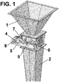
- the drawings depict the product discharge control device according to the present invention, comprising a hopper 1 where the metered product amount used for filling the bag is discharged and a fill tube 2, connecting the discharge control device according to the present invention to the fill nozzle of the form-fill-seal machine.
- the control device also comprises discharge control elements 3 that are movable between an open position in which product discharge is allowed, and a closed position in which product discharge is prevented, which allows receiving in this closed position a new metered product amount discharge released by the metering and weighing system located upstream.
- Said discharge control elements 3 are arranged between the hopper 1 and the fill tube 2, as seen in the drawings, and allow controlling product discharge towards the fill nozzle of the form-fill-seal machine.
- said discharge control elements 3 are swinging blades, although they could be any suitable discharge control element that is equivalent in terms of function.
- the driving means which allow the movement of said discharge control elements 3 comprise a connecting rod-crank mechanism that will be described below, driven by means of a motor 7, for example, by means of a servomotor.
- Said connecting rod-crank mechanism comprises a crank 8 connected to the output shaft of the motor 7 and a second connecting rod 4 connected thereto at one of its ends.
- the other opposite end of this second connecting rod 4 is in turn connected to one of the ends of the lever 5 integral with the rotating shaft of one of the discharge control elements 3.
- the rotational movement of the first lever 5 is transmitted to the second lever 6, which is integral with the rotating shaft of the second of the discharge control elements 3, in a synchronous manner by means of the synchronizing connecting rod 9.
- said crank 8 and said connecting rod second 4 are in a dead center position, i.e., in the position defined by the kinematics of this mechanism, in which an increase in rotation of the crank 8 in the same direction makes the second connecting rod 4 move in the direction opposite the one in which it was moving up until this time, which allows adjusting the position of the discharge control elements on the discharge hopper outlet profile, without any collisions occurring at the closing point, since the connecting rod-crank mechanism itself limits the maximum angular position the discharge control elements 3 reach with respect to the discharge hopper outlet profile.
- discharge control elements 3 can also be placed in different positions of the angle defined by said discharge control elements 3 during the product discharge cycle to obtain the shortest discharge time of all the product contents. Said positions of the discharge control elements can be fixed during the entire discharge cycle, or they can be variable and controlled by the automaton effecting discharge control during this cycle.
- the angle defined by said discharge control elements 3 with respect to the horizontal, indicated in Figures 2 and 3 by means of the letter "a”, is preferably comprised between 50° and 90°.
- the hopper 1 In the closed position, in the dead center position of the connecting rod-crank mechanism, the hopper 1 is filled with the metered product amount to be filled or discharged into the bag.
- the discharge control elements 3 move following the opening cycle pre-established by the control system for discharging the metered product amount in a controlled manner.
- the movement of the discharge control elements 3 is achieved by means of driving the connecting rod-crank mechanism described above by means of the motor 7.
- the discharge control elements 3 move to the closed position following the closing cycle pre-established by the control system, also by means of the connecting rod-crank mechanism and the motor 7.
- the angular movement trajectory (angular positions and speeds) of the discharge control elements during the opening and closing cycle can be programmed and/or adjusted by means of the control automaton for the purpose of obtaining the shortest time for the complete metered product amount discharge.
- the cycle is repeated again as soon as the device receives a new metered product amount, and the form-fill-seal machine requests a new discharge.
- Figure 4 shows a second embodiment of the discharge control device according to the present invention.
- the driving means of the discharge control elements also comprise first and second levers 5, 6 connected by means of said synchronizing connecting rod 9, each integral with a shaft for moving each of said discharge control elements 3, and the movement of which is driven by means of a drive belt 10 located between the output shaft of the motor 7, preferably a servomotor, and one of said levers 5, 6.
- Figure 5 shows a third embodiment of the discharge control device according to the present invention.
- the driving means also comprise first and second levers 5, 6 connected by means of said synchronizing connecting rod 9, each integral with a shaft for moving each of said discharge control elements 3, and the movement of which is driven by means of the output shaft of the motor 7 directly driving one of said levers 5, 6.
Landscapes
- Engineering & Computer Science (AREA)
- Mechanical Engineering (AREA)
- Quality & Reliability (AREA)
- Basic Packing Technique (AREA)
- Supply Of Fluid Materials To The Packaging Location (AREA)
Priority Applications (3)
| Application Number | Priority Date | Filing Date | Title |
|---|---|---|---|
| EP16382544.1A EP3323732B1 (de) | 2016-11-22 | 2016-11-22 | Produktentladungssteuerungsvorrichtung für eine form-füll-siegelmaschine |
| ES16382544T ES2767649T3 (es) | 2016-11-22 | 2016-11-22 | Dispositivo de control de descarga de producto para una máquina formadora, llenadora, selladora |
| US15/820,956 US10730650B2 (en) | 2016-11-22 | 2017-11-22 | Product discharge control device for a form-fill-seal machine |
Applications Claiming Priority (1)
| Application Number | Priority Date | Filing Date | Title |
|---|---|---|---|
| EP16382544.1A EP3323732B1 (de) | 2016-11-22 | 2016-11-22 | Produktentladungssteuerungsvorrichtung für eine form-füll-siegelmaschine |
Publications (2)
| Publication Number | Publication Date |
|---|---|
| EP3323732A1 true EP3323732A1 (de) | 2018-05-23 |
| EP3323732B1 EP3323732B1 (de) | 2019-12-25 |
Family
ID=57799519
Family Applications (1)
| Application Number | Title | Priority Date | Filing Date |
|---|---|---|---|
| EP16382544.1A Active EP3323732B1 (de) | 2016-11-22 | 2016-11-22 | Produktentladungssteuerungsvorrichtung für eine form-füll-siegelmaschine |
Country Status (3)
| Country | Link |
|---|---|
| US (1) | US10730650B2 (de) |
| EP (1) | EP3323732B1 (de) |
| ES (1) | ES2767649T3 (de) |
Cited By (2)
| Publication number | Priority date | Publication date | Assignee | Title |
|---|---|---|---|---|
| CN111056054A (zh) * | 2019-12-31 | 2020-04-24 | 三只松鼠(无为)有限责任公司 | 应用于工业互联网的灌装机下料机 |
| EP3936443B1 (de) | 2019-03-07 | 2023-01-18 | Tecnicas Mecanicas Ilerdenses, S.L. | Durchflussregelungssystem zur befüllung eines sacks mit einem körnigen produkt und zughörige maschine und verfahren |
Citations (4)
| Publication number | Priority date | Publication date | Assignee | Title |
|---|---|---|---|---|
| US5168906A (en) | 1990-04-26 | 1992-12-08 | Haver & Boecker | Apparatus for filling bags with flowable bulk material and method of adjusting the apparatus |
| EP1956351A1 (de) * | 2005-12-01 | 2008-08-13 | Ishida Co., Ltd. | Messgerät |
| ES2334474A1 (es) | 2007-03-26 | 2010-03-10 | Payper, S.A. | Tubo de aceleracion o tubo de llenado por gravedad para descarga de material pulvurulento o granulado. |
| EP2843379A1 (de) * | 2012-04-23 | 2015-03-04 | Yamato Scale Co., Ltd. | Wägeeinrichtung |
Family Cites Families (5)
| Publication number | Priority date | Publication date | Assignee | Title |
|---|---|---|---|---|
| GB8621259D0 (en) * | 1986-09-03 | 1986-10-08 | W J Morray Engineering Limited | Filling bag with articles |
| JP5786210B2 (ja) * | 2010-09-03 | 2015-09-30 | 株式会社タカゾノテクノロジー | ホッパー及びこれを備えた薬剤供給装置 |
| JP5918980B2 (ja) * | 2011-02-04 | 2016-05-18 | 株式会社イシダ | 製袋包装機 |
| EP2707291A2 (de) * | 2011-05-10 | 2014-03-19 | GEA Food Solutions Weert B.V. | Versiegelungssystem für eine verpackungsmaschine |
| US10723492B2 (en) * | 2017-09-21 | 2020-07-28 | Yamato Corporation | Depositor apparatus |
-
2016
- 2016-11-22 ES ES16382544T patent/ES2767649T3/es active Active
- 2016-11-22 EP EP16382544.1A patent/EP3323732B1/de active Active
-
2017
- 2017-11-22 US US15/820,956 patent/US10730650B2/en active Active
Patent Citations (4)
| Publication number | Priority date | Publication date | Assignee | Title |
|---|---|---|---|---|
| US5168906A (en) | 1990-04-26 | 1992-12-08 | Haver & Boecker | Apparatus for filling bags with flowable bulk material and method of adjusting the apparatus |
| EP1956351A1 (de) * | 2005-12-01 | 2008-08-13 | Ishida Co., Ltd. | Messgerät |
| ES2334474A1 (es) | 2007-03-26 | 2010-03-10 | Payper, S.A. | Tubo de aceleracion o tubo de llenado por gravedad para descarga de material pulvurulento o granulado. |
| EP2843379A1 (de) * | 2012-04-23 | 2015-03-04 | Yamato Scale Co., Ltd. | Wägeeinrichtung |
Cited By (2)
| Publication number | Priority date | Publication date | Assignee | Title |
|---|---|---|---|---|
| EP3936443B1 (de) | 2019-03-07 | 2023-01-18 | Tecnicas Mecanicas Ilerdenses, S.L. | Durchflussregelungssystem zur befüllung eines sacks mit einem körnigen produkt und zughörige maschine und verfahren |
| CN111056054A (zh) * | 2019-12-31 | 2020-04-24 | 三只松鼠(无为)有限责任公司 | 应用于工业互联网的灌装机下料机 |
Also Published As
| Publication number | Publication date |
|---|---|
| US10730650B2 (en) | 2020-08-04 |
| US20180141690A1 (en) | 2018-05-24 |
| ES2767649T3 (es) | 2020-06-18 |
| EP3323732B1 (de) | 2019-12-25 |
Similar Documents
| Publication | Publication Date | Title |
|---|---|---|
| EP2889590B1 (de) | Verfahren zum Füllen von Säcken mit einer Dosiermenge von Schüttgut, Vorrichtung und automatische Maschine zur Umsetzung des Verfahrens | |
| CN108995845B (zh) | 智能包装机 | |
| US10220969B2 (en) | Direct to container system with on-line weight control and associated method | |
| US20040182469A1 (en) | Apparatus for filling bags with loose material and automatic machine equipped with said apparatus | |
| US10730650B2 (en) | Product discharge control device for a form-fill-seal machine | |
| EP3592649B1 (de) | Dosiervorrichtung zum zuführung eines infusionsprodukts | |
| CN208715520U (zh) | 一种配合料生产自动定量包装装置 | |
| US4451954A (en) | Apparatus for consecutively metering discrete amounts of a divisible mass, particularly sausage-meat | |
| CN209209087U (zh) | 一种精密称重给料机 | |
| CN211108120U (zh) | 一种中药饮片的分装称重设备 | |
| CN105638840A (zh) | 用以收集并填充的分离驱动装置 | |
| CN110589039A (zh) | 一种变量给料装置及具有该变量给料装置的定量包装机 | |
| JP2016169037A (ja) | 包装装置 | |
| EP2233201A2 (de) | Für Verpackungsmaschine verwendbare Misch-Mess-Vorrichtung für zwei morphologisch unterschiedliche fließfähige Produkte | |
| US10723495B2 (en) | Bag opening device for form-fill-seal machines | |
| JP7022533B2 (ja) | 包装アセンブリ | |
| US4143725A (en) | Method and apparatus for separating bulk elongated products into quantities of predetermined weight | |
| EP3206960B1 (de) | Vorrichtung und verfahren zur zuführung und dosierung von filterbeuteln mit infusions- oder extraktionsprodukten | |
| EP3936443B1 (de) | Durchflussregelungssystem zur befüllung eines sacks mit einem körnigen produkt und zughörige maschine und verfahren | |
| CN210822857U (zh) | 一种变量给料装置及具有该变量给料装置的定量包装机 | |
| EP0744597A2 (de) | Vorrichtung zur Regelung der Materialzuführung an eine Waage | |
| CN210618526U (zh) | 自动灌装机 | |
| US5054993A (en) | Rotary intercept stacking apparatus and method | |
| DK176530B1 (da) | Fremgangsmåde og apparat til fyldning af fortrinsvis höjviskös iskrem i en beholder | |
| CN212386728U (zh) | 一种包装装置及包装存储机构 |
Legal Events
| Date | Code | Title | Description |
|---|---|---|---|
| PUAI | Public reference made under article 153(3) epc to a published international application that has entered the european phase |
Free format text: ORIGINAL CODE: 0009012 |
|
| STAA | Information on the status of an ep patent application or granted ep patent |
Free format text: STATUS: THE APPLICATION HAS BEEN PUBLISHED |
|
| AK | Designated contracting states |
Kind code of ref document: A1 Designated state(s): AL AT BE BG CH CY CZ DE DK EE ES FI FR GB GR HR HU IE IS IT LI LT LU LV MC MK MT NL NO PL PT RO RS SE SI SK SM TR |
|
| AX | Request for extension of the european patent |
Extension state: BA ME |
|
| STAA | Information on the status of an ep patent application or granted ep patent |
Free format text: STATUS: REQUEST FOR EXAMINATION WAS MADE |
|
| 17P | Request for examination filed |
Effective date: 20181122 |
|
| RBV | Designated contracting states (corrected) |
Designated state(s): AL AT BE BG CH CY CZ DE DK EE ES FI FR GB GR HR HU IE IS IT LI LT LU LV MC MK MT NL NO PL PT RO RS SE SI SK SM TR |
|
| GRAP | Despatch of communication of intention to grant a patent |
Free format text: ORIGINAL CODE: EPIDOSNIGR1 |
|
| STAA | Information on the status of an ep patent application or granted ep patent |
Free format text: STATUS: GRANT OF PATENT IS INTENDED |
|
| INTG | Intention to grant announced |
Effective date: 20190717 |
|
| GRAS | Grant fee paid |
Free format text: ORIGINAL CODE: EPIDOSNIGR3 |
|
| GRAA | (expected) grant |
Free format text: ORIGINAL CODE: 0009210 |
|
| STAA | Information on the status of an ep patent application or granted ep patent |
Free format text: STATUS: THE PATENT HAS BEEN GRANTED |
|
| AK | Designated contracting states |
Kind code of ref document: B1 Designated state(s): AL AT BE BG CH CY CZ DE DK EE ES FI FR GB GR HR HU IE IS IT LI LT LU LV MC MK MT NL NO PL PT RO RS SE SI SK SM TR |
|
| REG | Reference to a national code |
Ref country code: GB Ref legal event code: FG4D |
|
| REG | Reference to a national code |
Ref country code: CH Ref legal event code: EP |
|
| REG | Reference to a national code |
Ref country code: AT Ref legal event code: REF Ref document number: 1216854 Country of ref document: AT Kind code of ref document: T Effective date: 20200115 |
|
| REG | Reference to a national code |
Ref country code: DE Ref legal event code: R096 Ref document number: 602016026778 Country of ref document: DE |
|
| REG | Reference to a national code |
Ref country code: IE Ref legal event code: FG4D |
|
| REG | Reference to a national code |
Ref country code: NL Ref legal event code: MP Effective date: 20191225 |
|
| PG25 | Lapsed in a contracting state [announced via postgrant information from national office to epo] |
Ref country code: LT Free format text: LAPSE BECAUSE OF FAILURE TO SUBMIT A TRANSLATION OF THE DESCRIPTION OR TO PAY THE FEE WITHIN THE PRESCRIBED TIME-LIMIT Effective date: 20191225 Ref country code: GR Free format text: LAPSE BECAUSE OF FAILURE TO SUBMIT A TRANSLATION OF THE DESCRIPTION OR TO PAY THE FEE WITHIN THE PRESCRIBED TIME-LIMIT Effective date: 20200326 Ref country code: NO Free format text: LAPSE BECAUSE OF FAILURE TO SUBMIT A TRANSLATION OF THE DESCRIPTION OR TO PAY THE FEE WITHIN THE PRESCRIBED TIME-LIMIT Effective date: 20200325 Ref country code: BG Free format text: LAPSE BECAUSE OF FAILURE TO SUBMIT A TRANSLATION OF THE DESCRIPTION OR TO PAY THE FEE WITHIN THE PRESCRIBED TIME-LIMIT Effective date: 20200325 Ref country code: FI Free format text: LAPSE BECAUSE OF FAILURE TO SUBMIT A TRANSLATION OF THE DESCRIPTION OR TO PAY THE FEE WITHIN THE PRESCRIBED TIME-LIMIT Effective date: 20191225 Ref country code: LV Free format text: LAPSE BECAUSE OF FAILURE TO SUBMIT A TRANSLATION OF THE DESCRIPTION OR TO PAY THE FEE WITHIN THE PRESCRIBED TIME-LIMIT Effective date: 20191225 Ref country code: SE Free format text: LAPSE BECAUSE OF FAILURE TO SUBMIT A TRANSLATION OF THE DESCRIPTION OR TO PAY THE FEE WITHIN THE PRESCRIBED TIME-LIMIT Effective date: 20191225 |
|
| REG | Reference to a national code |
Ref country code: LT Ref legal event code: MG4D |
|
| PG25 | Lapsed in a contracting state [announced via postgrant information from national office to epo] |
Ref country code: RS Free format text: LAPSE BECAUSE OF FAILURE TO SUBMIT A TRANSLATION OF THE DESCRIPTION OR TO PAY THE FEE WITHIN THE PRESCRIBED TIME-LIMIT Effective date: 20191225 Ref country code: HR Free format text: LAPSE BECAUSE OF FAILURE TO SUBMIT A TRANSLATION OF THE DESCRIPTION OR TO PAY THE FEE WITHIN THE PRESCRIBED TIME-LIMIT Effective date: 20191225 |
|
| REG | Reference to a national code |
Ref country code: ES Ref legal event code: FG2A Ref document number: 2767649 Country of ref document: ES Kind code of ref document: T3 Effective date: 20200618 |
|
| PG25 | Lapsed in a contracting state [announced via postgrant information from national office to epo] |
Ref country code: AL Free format text: LAPSE BECAUSE OF FAILURE TO SUBMIT A TRANSLATION OF THE DESCRIPTION OR TO PAY THE FEE WITHIN THE PRESCRIBED TIME-LIMIT Effective date: 20191225 |
|
| PG25 | Lapsed in a contracting state [announced via postgrant information from national office to epo] |
Ref country code: EE Free format text: LAPSE BECAUSE OF FAILURE TO SUBMIT A TRANSLATION OF THE DESCRIPTION OR TO PAY THE FEE WITHIN THE PRESCRIBED TIME-LIMIT Effective date: 20191225 Ref country code: NL Free format text: LAPSE BECAUSE OF FAILURE TO SUBMIT A TRANSLATION OF THE DESCRIPTION OR TO PAY THE FEE WITHIN THE PRESCRIBED TIME-LIMIT Effective date: 20191225 Ref country code: PT Free format text: LAPSE BECAUSE OF FAILURE TO SUBMIT A TRANSLATION OF THE DESCRIPTION OR TO PAY THE FEE WITHIN THE PRESCRIBED TIME-LIMIT Effective date: 20200520 Ref country code: CZ Free format text: LAPSE BECAUSE OF FAILURE TO SUBMIT A TRANSLATION OF THE DESCRIPTION OR TO PAY THE FEE WITHIN THE PRESCRIBED TIME-LIMIT Effective date: 20191225 Ref country code: RO Free format text: LAPSE BECAUSE OF FAILURE TO SUBMIT A TRANSLATION OF THE DESCRIPTION OR TO PAY THE FEE WITHIN THE PRESCRIBED TIME-LIMIT Effective date: 20191225 |
|
| PG25 | Lapsed in a contracting state [announced via postgrant information from national office to epo] |
Ref country code: SK Free format text: LAPSE BECAUSE OF FAILURE TO SUBMIT A TRANSLATION OF THE DESCRIPTION OR TO PAY THE FEE WITHIN THE PRESCRIBED TIME-LIMIT Effective date: 20191225 Ref country code: IS Free format text: LAPSE BECAUSE OF FAILURE TO SUBMIT A TRANSLATION OF THE DESCRIPTION OR TO PAY THE FEE WITHIN THE PRESCRIBED TIME-LIMIT Effective date: 20200425 Ref country code: SM Free format text: LAPSE BECAUSE OF FAILURE TO SUBMIT A TRANSLATION OF THE DESCRIPTION OR TO PAY THE FEE WITHIN THE PRESCRIBED TIME-LIMIT Effective date: 20191225 |
|
| REG | Reference to a national code |
Ref country code: DE Ref legal event code: R097 Ref document number: 602016026778 Country of ref document: DE |
|
| PG25 | Lapsed in a contracting state [announced via postgrant information from national office to epo] |
Ref country code: DK Free format text: LAPSE BECAUSE OF FAILURE TO SUBMIT A TRANSLATION OF THE DESCRIPTION OR TO PAY THE FEE WITHIN THE PRESCRIBED TIME-LIMIT Effective date: 20191225 |
|
| PLBE | No opposition filed within time limit |
Free format text: ORIGINAL CODE: 0009261 |
|
| STAA | Information on the status of an ep patent application or granted ep patent |
Free format text: STATUS: NO OPPOSITION FILED WITHIN TIME LIMIT |
|
| REG | Reference to a national code |
Ref country code: AT Ref legal event code: MK05 Ref document number: 1216854 Country of ref document: AT Kind code of ref document: T Effective date: 20191225 |
|
| PG25 | Lapsed in a contracting state [announced via postgrant information from national office to epo] |
Ref country code: SI Free format text: LAPSE BECAUSE OF FAILURE TO SUBMIT A TRANSLATION OF THE DESCRIPTION OR TO PAY THE FEE WITHIN THE PRESCRIBED TIME-LIMIT Effective date: 20191225 |
|
| 26N | No opposition filed |
Effective date: 20200928 |
|
| PG25 | Lapsed in a contracting state [announced via postgrant information from national office to epo] |
Ref country code: AT Free format text: LAPSE BECAUSE OF FAILURE TO SUBMIT A TRANSLATION OF THE DESCRIPTION OR TO PAY THE FEE WITHIN THE PRESCRIBED TIME-LIMIT Effective date: 20191225 |
|
| PG25 | Lapsed in a contracting state [announced via postgrant information from national office to epo] |
Ref country code: PL Free format text: LAPSE BECAUSE OF FAILURE TO SUBMIT A TRANSLATION OF THE DESCRIPTION OR TO PAY THE FEE WITHIN THE PRESCRIBED TIME-LIMIT Effective date: 20191225 |
|
| PG25 | Lapsed in a contracting state [announced via postgrant information from national office to epo] |
Ref country code: MC Free format text: LAPSE BECAUSE OF FAILURE TO SUBMIT A TRANSLATION OF THE DESCRIPTION OR TO PAY THE FEE WITHIN THE PRESCRIBED TIME-LIMIT Effective date: 20191225 |
|
| REG | Reference to a national code |
Ref country code: CH Ref legal event code: PL |
|
| GBPC | Gb: european patent ceased through non-payment of renewal fee |
Effective date: 20201122 |
|
| PG25 | Lapsed in a contracting state [announced via postgrant information from national office to epo] |
Ref country code: LU Free format text: LAPSE BECAUSE OF NON-PAYMENT OF DUE FEES Effective date: 20201122 |
|
| REG | Reference to a national code |
Ref country code: BE Ref legal event code: MM Effective date: 20201130 |
|
| PG25 | Lapsed in a contracting state [announced via postgrant information from national office to epo] |
Ref country code: LI Free format text: LAPSE BECAUSE OF NON-PAYMENT OF DUE FEES Effective date: 20201130 Ref country code: CH Free format text: LAPSE BECAUSE OF NON-PAYMENT OF DUE FEES Effective date: 20201130 |
|
| PG25 | Lapsed in a contracting state [announced via postgrant information from national office to epo] |
Ref country code: FR Free format text: LAPSE BECAUSE OF NON-PAYMENT OF DUE FEES Effective date: 20201130 Ref country code: IE Free format text: LAPSE BECAUSE OF NON-PAYMENT OF DUE FEES Effective date: 20201122 |
|
| PG25 | Lapsed in a contracting state [announced via postgrant information from national office to epo] |
Ref country code: GB Free format text: LAPSE BECAUSE OF NON-PAYMENT OF DUE FEES Effective date: 20201122 |
|
| PG25 | Lapsed in a contracting state [announced via postgrant information from national office to epo] |
Ref country code: TR Free format text: LAPSE BECAUSE OF FAILURE TO SUBMIT A TRANSLATION OF THE DESCRIPTION OR TO PAY THE FEE WITHIN THE PRESCRIBED TIME-LIMIT Effective date: 20191225 Ref country code: MT Free format text: LAPSE BECAUSE OF FAILURE TO SUBMIT A TRANSLATION OF THE DESCRIPTION OR TO PAY THE FEE WITHIN THE PRESCRIBED TIME-LIMIT Effective date: 20191225 Ref country code: CY Free format text: LAPSE BECAUSE OF FAILURE TO SUBMIT A TRANSLATION OF THE DESCRIPTION OR TO PAY THE FEE WITHIN THE PRESCRIBED TIME-LIMIT Effective date: 20191225 |
|
| PG25 | Lapsed in a contracting state [announced via postgrant information from national office to epo] |
Ref country code: MK Free format text: LAPSE BECAUSE OF FAILURE TO SUBMIT A TRANSLATION OF THE DESCRIPTION OR TO PAY THE FEE WITHIN THE PRESCRIBED TIME-LIMIT Effective date: 20191225 |
|
| PG25 | Lapsed in a contracting state [announced via postgrant information from national office to epo] |
Ref country code: BE Free format text: LAPSE BECAUSE OF NON-PAYMENT OF DUE FEES Effective date: 20201130 |
|
| P01 | Opt-out of the competence of the unified patent court (upc) registered |
Effective date: 20230508 |
|
| PGFP | Annual fee paid to national office [announced via postgrant information from national office to epo] |
Ref country code: DE Payment date: 20251124 Year of fee payment: 10 |
|
| PGFP | Annual fee paid to national office [announced via postgrant information from national office to epo] |
Ref country code: IT Payment date: 20251104 Year of fee payment: 10 |
|
| PGFP | Annual fee paid to national office [announced via postgrant information from national office to epo] |
Ref country code: ES Payment date: 20251201 Year of fee payment: 10 |