EP3323955A1 - Support profilé en acier - Google Patents
Support profilé en acier Download PDFInfo
- Publication number
- EP3323955A1 EP3323955A1 EP17183426.0A EP17183426A EP3323955A1 EP 3323955 A1 EP3323955 A1 EP 3323955A1 EP 17183426 A EP17183426 A EP 17183426A EP 3323955 A1 EP3323955 A1 EP 3323955A1
- Authority
- EP
- European Patent Office
- Prior art keywords
- profile
- steel
- groove
- support
- carrier
- Prior art date
- Legal status (The legal status is an assumption and is not a legal conclusion. Google has not performed a legal analysis and makes no representation as to the accuracy of the status listed.)
- Withdrawn
Links
- 229910000831 Steel Inorganic materials 0.000 title claims abstract description 129
- 239000010959 steel Substances 0.000 title claims abstract description 129
- 230000002093 peripheral effect Effects 0.000 claims abstract description 68
- XLYOFNOQVPJJNP-UHFFFAOYSA-N water Substances O XLYOFNOQVPJJNP-UHFFFAOYSA-N 0.000 claims abstract description 9
- 239000000463 material Substances 0.000 claims description 6
- 238000009434 installation Methods 0.000 description 9
- 238000005096 rolling process Methods 0.000 description 6
- 239000011248 coating agent Substances 0.000 description 5
- 238000000576 coating method Methods 0.000 description 5
- 238000004519 manufacturing process Methods 0.000 description 5
- 238000005452 bending Methods 0.000 description 4
- 230000006378 damage Effects 0.000 description 4
- 238000003466 welding Methods 0.000 description 4
- 241000251131 Sphyrna Species 0.000 description 3
- 230000007704 transition Effects 0.000 description 3
- 208000027418 Wounds and injury Diseases 0.000 description 2
- 238000005246 galvanizing Methods 0.000 description 2
- 208000014674 injury Diseases 0.000 description 2
- HCHKCACWOHOZIP-UHFFFAOYSA-N Zinc Chemical compound [Zn] HCHKCACWOHOZIP-UHFFFAOYSA-N 0.000 description 1
- 230000001154 acute effect Effects 0.000 description 1
- 230000007797 corrosion Effects 0.000 description 1
- 238000005260 corrosion Methods 0.000 description 1
- 230000000694 effects Effects 0.000 description 1
- 238000004049 embossing Methods 0.000 description 1
- 238000010438 heat treatment Methods 0.000 description 1
- 239000007788 liquid Substances 0.000 description 1
- 238000004080 punching Methods 0.000 description 1
- 238000006748 scratching Methods 0.000 description 1
- 230000002393 scratching effect Effects 0.000 description 1
- 230000003068 static effect Effects 0.000 description 1
- 238000013024 troubleshooting Methods 0.000 description 1
- 238000009736 wetting Methods 0.000 description 1
- 239000011701 zinc Substances 0.000 description 1
- 229910052725 zinc Inorganic materials 0.000 description 1
Images


Classifications
-
- E—FIXED CONSTRUCTIONS
- E04—BUILDING
- E04C—STRUCTURAL ELEMENTS; BUILDING MATERIALS
- E04C3/00—Structural elongated elements designed for load-supporting
- E04C3/02—Joists; Girders, trusses, or trusslike structures, e.g. prefabricated; Lintels; Transoms; Braces
- E04C3/04—Joists; Girders, trusses, or trusslike structures, e.g. prefabricated; Lintels; Transoms; Braces of metal
- E04C3/06—Joists; Girders, trusses, or trusslike structures, e.g. prefabricated; Lintels; Transoms; Braces of metal with substantially solid, i.e. unapertured, web
- E04C3/07—Joists; Girders, trusses, or trusslike structures, e.g. prefabricated; Lintels; Transoms; Braces of metal with substantially solid, i.e. unapertured, web at least partly of bent or otherwise deformed strip- or sheet-like material
-
- E—FIXED CONSTRUCTIONS
- E04—BUILDING
- E04C—STRUCTURAL ELEMENTS; BUILDING MATERIALS
- E04C3/00—Structural elongated elements designed for load-supporting
- E04C3/02—Joists; Girders, trusses, or trusslike structures, e.g. prefabricated; Lintels; Transoms; Braces
- E04C3/04—Joists; Girders, trusses, or trusslike structures, e.g. prefabricated; Lintels; Transoms; Braces of metal
- E04C2003/0404—Joists; Girders, trusses, or trusslike structures, e.g. prefabricated; Lintels; Transoms; Braces of metal beams, girders, or joists characterised by cross-sectional aspects
- E04C2003/0408—Joists; Girders, trusses, or trusslike structures, e.g. prefabricated; Lintels; Transoms; Braces of metal beams, girders, or joists characterised by cross-sectional aspects characterised by assembly or the cross-section
- E04C2003/0421—Joists; Girders, trusses, or trusslike structures, e.g. prefabricated; Lintels; Transoms; Braces of metal beams, girders, or joists characterised by cross-sectional aspects characterised by assembly or the cross-section comprising one single unitary part
-
- E—FIXED CONSTRUCTIONS
- E04—BUILDING
- E04C—STRUCTURAL ELEMENTS; BUILDING MATERIALS
- E04C3/00—Structural elongated elements designed for load-supporting
- E04C3/02—Joists; Girders, trusses, or trusslike structures, e.g. prefabricated; Lintels; Transoms; Braces
- E04C3/04—Joists; Girders, trusses, or trusslike structures, e.g. prefabricated; Lintels; Transoms; Braces of metal
- E04C2003/0404—Joists; Girders, trusses, or trusslike structures, e.g. prefabricated; Lintels; Transoms; Braces of metal beams, girders, or joists characterised by cross-sectional aspects
- E04C2003/0426—Joists; Girders, trusses, or trusslike structures, e.g. prefabricated; Lintels; Transoms; Braces of metal beams, girders, or joists characterised by cross-sectional aspects characterised by material distribution in cross section
- E04C2003/0439—Joists; Girders, trusses, or trusslike structures, e.g. prefabricated; Lintels; Transoms; Braces of metal beams, girders, or joists characterised by cross-sectional aspects characterised by material distribution in cross section the cross-section comprising open parts and hollow parts
-
- E—FIXED CONSTRUCTIONS
- E04—BUILDING
- E04C—STRUCTURAL ELEMENTS; BUILDING MATERIALS
- E04C3/00—Structural elongated elements designed for load-supporting
- E04C3/02—Joists; Girders, trusses, or trusslike structures, e.g. prefabricated; Lintels; Transoms; Braces
- E04C3/04—Joists; Girders, trusses, or trusslike structures, e.g. prefabricated; Lintels; Transoms; Braces of metal
- E04C2003/0404—Joists; Girders, trusses, or trusslike structures, e.g. prefabricated; Lintels; Transoms; Braces of metal beams, girders, or joists characterised by cross-sectional aspects
- E04C2003/0443—Joists; Girders, trusses, or trusslike structures, e.g. prefabricated; Lintels; Transoms; Braces of metal beams, girders, or joists characterised by cross-sectional aspects characterised by substantial shape of the cross-section
- E04C2003/0465—Joists; Girders, trusses, or trusslike structures, e.g. prefabricated; Lintels; Transoms; Braces of metal beams, girders, or joists characterised by cross-sectional aspects characterised by substantial shape of the cross-section square- or rectangular-shaped
Definitions
- the invention relates to a steel profile support, which may also be referred to as a support profile or mounting profile made of steel, for Anmontieren of lines, such as water pipes, power cables or the like.
- the steel profile support according to the invention can be used for example in cantilevered halls, which are held primarily by concrete columns, which are arranged at a distance of usually more than 5 m from each other.
- cantilevered halls which are held primarily by concrete columns, which are arranged at a distance of usually more than 5 m from each other.
- neither the roof (a trapezoidal sheet) nor the side panels (sandwich panels) may be subjected to static loads.
- supporting profiles can be mounted laterally on concrete pillars or transversely between concrete supports in order to carry cables to be laid in the self-supporting hall.
- a generic support profile made of steel is known from the utility model DE 20 2005 006 528 U1 ,
- the known support profile has a substantially square profile cross-section, which is formed by four adjoining profile peripheral walls.
- continuous fastening grooves are formed on two opposite profile peripheral walls in the profile longitudinal direction.
- successive punched perforations in the form of individual slots are formed in each case in a row.
- the generic support profile is versatile, especially in the installation area, for example, communication and data lines, supply lines of various kinds, such as electrical supply lines, supply lines for the gas and water supply, hot water supply, pipes for heating, sewers, etc.
- known support profiles for example, with elbows, attached to each other or on walls, ceilings or floors of buildings.
- slotted holes provided in the slotted profile peripheral walls allow attaching, for example, pipe clamps for piping or the like to install pipes.
- hammer head screws or wedge head screws can be introduced with their hammer or wedge head to For example, to attach two support profiles together. Due to the simple assembly, the known support profile has proven very successful in practice.
- U1 known supporting profile are provided diametrically opposite profile peripheral wall pairs either with slots or with mounting grooves.
- the slots are to allow a connection of functional elements of various kinds, while the mounting groove should accommodate hammerhead screws, so that different types of attachment are available.
- the mounting direction is either a slot side wall or a mounting groove side wall front side for mounting additional functional elements or attachments ready.
- a steel profile support for mounting lines, such as communication and data lines, supply lines, for example for gas, water or hot water supply, sewers or the like provided, the four adjoining profile peripheral walls with a minimum wall thickness of 1 mm.
- Steel profile beams may have a length of more than 1 m, more than 5 m and / or less than 20 m, less than 10 m, preferably about 6 m.
- the steel profile carrier according to the invention has, in a longitudinal direction, preferably along at least 500 mm, 1000 mm or even its entire length, a substantially constant, rectangular cross-section transverse to the longitudinal direction.
- the rectangular profile cross section may have a substantially rectangular, preferably square, outer contour.
- all profile peripheral sides are substantially the same length and / or width. It is clear that the corners of the rectangle may in particular have manufacturing-related curves.
- the profile cross section has a side length of at least 50 mm, preferably between 50 mm and 150 mm, in particular about 100 mm.
- the introduction of notches, oblong holes or the like in profile walls or profile peripheral walls of the steel profile carrier is not to be regarded as a deviation from a substantially constant rectangular profile cross-section.
- the circumferential perimeter walls define planes that intersect each other at an angle of 90 ° ⁇ 5 °, preferably ⁇ 1 °.
- the contact of the perpendicular adjoining profile circumferential walls may preferably be formed and / or rounded by bending, rolling and / or welding, in particular butt welding, one or more steel sheets or steel strips.
- each of the four profile peripheral walls has at least one, preferably at least 500 mm, 1000 mm or completely along the steel profile support, longitudinally extending mounting grooves for receiving a mounting wedge, such as a hammer head nut or a hammer head of a hammer head screw for mounting the lines on.
- the respective fastening groove in the respectively associated circumferential profile wall defines a preferably elongate and / or slot-shaped opening.
- the respective fastening groove protrudes from its respective opening into the interior of the steel profile support and expands to form undercuts.
- the undercuts can serve as fastening abutment to be introduced into the mounting groove mounting wedge or hammer head of a hammer head screw.
- the fastening groove can be used, for example, for mounting lines by means of a fastening wedge or for fastening two steel profile beams to each other.
- the width of the opening transverse to the longitudinal direction of the steel profile carrier is smaller than a largest clear width of the mounting groove parallel to the width of the opening.
- the width of the opening may be between 5 mm and 30 mm, preferably between 10 mm and 15 mm, in particular about 13 mm.
- each attachment groove has two preferably diametrically opposed, the undercuts forming wings extending away from the opening and the transversely relative to a pointing in the steel profile carrier profile peripheral wall-vertical, preferably at an angle between 45 ° and 135 °, are oriented.
- one wing each may extend from a groove edge delimiting the opening and / or to a groove side face bounding the groove base transversely to the longitudinal direction.
- the groove edge referred to as a vertical peripheral direction, extends from a plane inwardly into the cross-sectional profile, the plane being defined by the profile circumferential wall in which the fastening groove, its Wing is described, is arranged.
- the fastening groove can provide an abutment for a fastening wedge with a predetermined spring action, which has proven to be advantageous in terms of assembly safety.
- the wings have relative to the pointing in the steel profile carrier Perimeter profile vertical walls each at an angle of at least 60 ° and at most 90 °, preferably at least 75 ° and at most 85 °, in particular about 78 °, on.
- a coating such as a galvanizing liquid
- the wings each have an angle of at least 90 ° and at most 120 °, preferably at least 100 ° and at most 110 °, in particular about 105 °, relative to the profile peripheral wall vertical pointing in the steel profile carrier.
- the wing is guided back toward the inside of the profile peripheral wall and may preferably be brought into inside contact with the profile peripheral wall, which increases the mounting strength of the steel profile carrier. Due to the increased stiffness of the wing setting phenomena that can lead to a reduction in the holding force of a hammer head mounting screw can be avoided.
- the steel profile support has a wall thickness which is preferably full, in particular also in the fastening grooves, and / or along its entire extent in the longitudinal direction.
- the wall thickness of the steel profile carrier is greater than 0.5 mm and / or smaller than 5.0 mm, in particular greater than 1.0 mm and / or smaller than 3 , 00 mm, preferably greater than 1.3 mm and / or less than 2.8 mm.
- the wall thickness is preferably greater than 1.1 mm and / or less than 1.3 mm, more preferably about 1.25 mm.
- the wall thickness is preferably greater than 1.3 mm and / or less than 1.7 mm, more preferably about 1.5 mm.
- the wall thickness is greater than 2.3 mm and / or less than 2.7 mm, particularly preferably about 2.5 mm.
- each fastening groove has two mutually opposite, the opening limiting groove edges, each having an outer radius of curvature.
- the outer radius of curvature of the groove edges is at least 1 mm and / or at most 5 mm, in particular about 1.8 mm or about 3 mm.
- the radius of curvature can be dimensioned depending on the preferably constant wall thickness of the steel profile carrier, in particular the radius of curvature can be at least 1.2 times or at most twice the wall thickness of the steel profile carrier.
- the radius of curvature of a groove edge can preferably pass on the one hand into the profile circumferential wall, in particular in an aligned and / or seamless manner, and on the other hand, in particular, pass into a wing forming an undercut of the fastening groove in a flush and / or seamless manner.
- the respective fastening groove is centered on each, i. the associated profile circumferential wall is formed, wherein in particular the preferably mirror-symmetrical fastening groove defines a fastening groove central axis.
- the center axis is preferably cut by the profile peripheral wall vertical, which is arranged at the same distance from the two adjacent profile peripheral walls, which are each provided laterally of the profile circumferential wall associated therewith to the fastening groove. Due to the mirror-symmetrical and central design of the mounting groove is ensured in a particularly simple manner that several steel profile support compatible with each other are particularly well suited for easy installation.
- each fastening groove has a closed inner contour, which may optionally be broken by punching, embossing, slots or the like.
- the fastening groove is formed integrally with the material of the associated circumferential profile wall.
- Such a mounting groove can be made in a particularly simple manner by bending or rolling rollers made of the same material as the profile peripheral wall, for example a steel strip.
- the attachment groove has a groove bottom surface which preferably extends plane-parallel to the profile peripheral wall in particular extending between the opening and the groove bottom surface opposing, preferably mutually plane-parallel and / or transversely, preferably perpendicular, to the groove bottom surface and / or the associated profile peripheral wall arranged groove side surfaces.
- the groove bottom between the opposite groove side surfaces has a clearance (a clearance) of at least 1.5 times the opening width and at most 5 times the opening width.
- the inside width between the opposite groove side surfaces measures at least 10 mm and / or at most 50 mm, preferably about 30 mm ⁇ 5 mm.
- the distance between the groove side surfaces may preferably be between one fifth and one third.
- the distance of the groove side surfaces in relation to the size of the opening width of the mounting groove and / or the side length of the associated peripheral profile wall allows for this dimensioning a particularly stable steel profile carrier design.
- the steel profile support is made of at least one steel strip, for example two, three or four steel strips, preferably a single steel strip.
- the steel profile carrier consists of a single or at least one steel strip.
- a steel profile carrier can be produced in a particularly simple manner by two preferably uniformly shaped steel strips, which each form two profile peripheral walls and are connected to one another along their end marginal edges by welds, preferably along their entire length.
- a continuous welded joint in Longitudinal direction along the edge of the steel strip realizes a particularly stable connection.
- the at least one preferably planed weld seam is arranged on a profile peripheral corner formed by two adjoining profile peripheral walls.
- the profile perimeter corners are particularly easy to access for welding machines.
- the steel profile support may be surface treated, for. B. melt-dip refined.
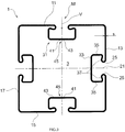
- the support profile according to the invention is generally characterized by the reference numeral 1.
- the steel profile support 1 can alternatively as a support profile or mounting profile be designated and is made as a closed box body profile.
- the steel profile support can be made for example by rolling or bending of a single steel strip. It is also conceivable to produce a steel profile carrier by rolling rolls of two or more steel strips and then welding the plurality of steel strips.
- the steel profile support 1 is made of a steel material which may be provided with a surface coating, such as zinc, for corrosion protection.
- the four profile circumferential walls 11, 13, 15, 17 which are diametrically opposite each other in pairs adjoin one another essentially at right angles.
- In the profile peripheral corners 12, 14, 16, 18 between each two adjacent circumferential profile walls 11 and 13, 13 and 15, 15 and 17 or 17 and 11 may, due to production, for example, due to bending or profile rolling, have curves.
- Each of the tread peripheral walls or tread portions 11, 13, 15, 17 is substantially the same length and width having a circumferential width of about 10 cm ⁇ 10 mm transverse to the longitudinal direction L of the support tread 1, so that the rectangular profile cross-section forms transversely to the longitudinal direction L.
- a steel profile support may be dimensioned such that each two mutually opposite profile peripheral walls have the same width, with one pair of opposed peripheral walls having a short circumferential width and the other pair of opposite circumferential walls having a long circumferential width.
- a short circumferential width may be 5 cm and an associated long circumferential width 10 cm.
- a short circumferential width may be 10 cm and the long circumferential width 15 cm.
- Such a steel profile carrier would have a rectangular profile cross-section with a substantially rectangular profile circumference.
- the distance x, y from the midpoint M of the opening 23 to the circumferential perimeter wall (e.g., 11 and 15) adjacent to the associated perimeter wall (e.g., 17) is about 50 mm for a square profile cross section.
- the distance of the center line M to the adjacent circumferential profile wall may preferably correspond to half of the shorter circumferential width.
- the center M of the slot opening 23 may be about 50 mm to the nearest adjacent circumferential profile wall.
- the profile carrier 1 extends in a longitudinal direction L over up to 10 m, with a length of 5 m to 7 m, in particular about 6 m ⁇ 30 cm is preferred. This length has become Use proven in customary cantilevered halls as particularly practical.
- the circumferential profile walls 11, 13, 15 and 17 extend parallel to each other and parallel to the longitudinal direction L with the fastening grooves 21 arranged centrally therein.
- the fastening grooves 21 in the illustrated preferred embodiment extend over the entire length of each circumferential profile wall 11, 13 , 15 and 17. It is also conceivable that a fastening groove extends only over a part of a circumferential profile wall. In one, two, three or all four mounting grooves 21 through openings, in particular slots (not shown) may be provided, which may serve for additional attachment of attachments.
- Each attachment groove 21 has a slot-shaped opening 23 formed in the peripheral profile wall 11, 13, 15, 17 having the respective attachment groove 21.
- the groove 21 extends like a pocket into the interior 3 of the steel profile support 1.
- the fastening groove 21 widens inwardly into the steel profile support 1 transversely to the longitudinal direction L and away from a center line M, the center along the longitudinal extent L of the opening 23 is defined, gone.
- the inwardly 3 in the steel profile support and away from the opening 23 projecting inner contour of the mounting groove 21 is realized by two diametrically opposite wings 37.
- the foot of the wings 37 is formed by a radial bend of the steel sheet, and forms an opening 23 of the mounting groove 21 delimiting groove edge 25.
- the steel sheet, which forms the peripheral profile walls 11, 13, 15, 17, is bent or folded over the groove edge 25 and merges with the wing 37 to form a radius of about 3 mm.
- the wing 37 realizes a return toward the outer side 53 of the profile circumferential walls 11, 13, 15 and 17.
- the profile peripheral wall 11, 13, 15 and 17 is substantially flat and defines a plane along the longitudinal direction L and across. Perpendicular to this plane preferably extends through the center line M of the opening 23 a profile peripheral wall vertical V, which is to be assumed with an orientation which is based on the respective profile peripheral wall 11, 13, 15 or 17 and directed into the interior 3 of the steel profile carrier 1 is.
- the vane 37 is oriented at an obtuse angle ⁇ relative to the profile peripheral wall vertical V.
- the angle ⁇ can be in a range between 90 ° and 135 °, and is preferably about 115 °. In this case (even at angle ⁇ ) is to be assumed by a tolerance band of ⁇ 5 °, with particularly accurate production ⁇ 1 ° 30 '.
- a retaining wedge or, for example, the hammer head of a hammer head bolt is inserted into the fastening groove 21, then it is supported in the embodiment according to FIG Fig. 1 to 3 on the inside of the fastening groove at a transition between the rounded Nutrand 25 and the wing 37 from.
- the wing 37 can be fed back to the inside 51 of the profile peripheral wall 11, 13, 15 and 17, so that the wing 37 to hold a fastening screw or the like to two Positions relative to the inner side 51 of the profile circumferential wall 11, 13, 15 and 17 are supported.
- the folding of the blade 37 at an angle of 90 ° or more relative to the circumferential profile wall V has also proved to be particularly advantageous in view of a roll-rolling production of a steel profile carrier 1 from a single steel strip.
- the representations of the Fig. 2 and 3 differ essentially only by the different wall thickness S, which in the steel profile carrier 1 in Fig. 3 about 1.5 mm ⁇ 0.1 mm and for the steel profile support 1 according to Fig. 3 is about 2.5 mm ⁇ 0.1 mm.
- the width B of the opening 23 of each attachment groove 21 is about 10 mm to 15 mm, preferably between 13 mm and 14 mm.
- the groove bottom has a clear width W of between 25 mm and 35 mm, preferably between 29 mm and 30 mm.
- the groove depth A perpendicular to the associated profile peripheral wall 11, 13, 15 and 17 is about 5 mm to 15 mm, preferably 10 mm ⁇ 0.5 mm.
- the groove base is formed by a flat groove bottom 33, which extends plane-parallel to the respective profile peripheral wall 11, 13, 15 and 17, in particular the outer side 53. Perpendicular to the profile bottom 33 and the respective profile peripheral wall 11, 13, 15 and 17 extend opposite plane-parallel side walls 35 of the groove 21. Since the groove edges 25, the wings 37, the groove sides 35 and the groove bottom 33 are integrally formed, preferably in one piece the corresponding profile peripheral wall 11, 13, 15 or 17, each groove 21 forms a closed pocket 31. In particular, at the groove bottom 33, the pocket 31 may be partially broken, for example, by a slot which preferably extends in the longitudinal direction L.
- the mounting groove 22 is particularly designed by coating or galvanizing that the wing 37 extends at a relatively acute angle relative to the profile peripheral wall vertical of the highest 90 °. In this way, between the inner side 51 of each belonging to the groove 22 profile peripheral wall 11, 13, 15 or 17 and the wing 37, a convex gap cavity whose smallest width is at the transition of the inner side 51 of the profile peripheral wall 11, 13, 15 and 17 to the curved groove edge 25 is present.
- the coating material can thus freely penetrate into the gap between the wing 37 and the profile peripheral wall 11, 13, 15, 17.
- the angle ⁇ between the profile peripheral wall vertical and the wing 37 is preferably between 45 ° and 90 °, in particular about 78 °.
- the inner dimensions of the mounting groove 22 correspond to the other angle ⁇ of the wing 37 substantially the above for Fig. 1 to 3 mentioned.
- the depth A of the groove 21 or 22 is generally measured at the shortest distance A between the groove bottom 33 and the wing 37, as shown this distance determines the maximum size of a deployable mounting wedge, such as a hammerhead of a hammerhead bolt.
- welds 55 which connect individual formed steel strips, shown at different possible locations of the profile carrier.
- the welds 45 each extend preferably in the longitudinal direction L over the entire length of the steel profile carrier 1 or 2.
- Fig. 2 shows a steel profile carrier 1, which is formed of a single steel strip and in which the weld 45 is provided in the profile peripheral corner 12 between the profile of the sides of the profile 11 and 13.
- the opposite longitudinal edges 41, 43 of the single steel strip extending in the longitudinal direction L come together.
- To injuries of the assembly personnel or damages, in particular scratching of surface coating To avoid the steel profile carrier along the weld 45 is surface-treated, for example by planing and / or grinding.
- the steel profile carrier 1 according to Fig. 3 consists of two steel bands, each extending laterally in the longitudinal direction L, and edge edges 41 and 43, which are set flush with each other and welded.
- steel profile support 2 are two in the longitudinal direction L over the entire length of the steel profile carrier 2 extending welds 45 in the opposite profile peripheral corners 12 and 16 are provided.
- the steel profile carrier 2 is formed from two formed sheets or steel strips whose respective peripheral edges 41 and 43 collide.
- angles (.alpha., .Beta.) Described in the respective embodiments can be variably combined between profile peripheral wall-vertical V and vane 37, wall thicknesses S and arrangement and number of weld seams 45.
- the features disclosed in the foregoing description, the figures and the claims may be of importance both individually and in any combination for the realization of the invention in various embodiments.
Landscapes
- Engineering & Computer Science (AREA)
- Architecture (AREA)
- Civil Engineering (AREA)
- Structural Engineering (AREA)
- Joining Of Building Structures In Genera (AREA)
- Connection Of Plates (AREA)
Applications Claiming Priority (1)
| Application Number | Priority Date | Filing Date | Title |
|---|---|---|---|
| DE102016122371.9A DE102016122371A1 (de) | 2016-11-21 | 2016-11-21 | Stahlprofilträger |
Publications (1)
| Publication Number | Publication Date |
|---|---|
| EP3323955A1 true EP3323955A1 (fr) | 2018-05-23 |
Family
ID=59485204
Family Applications (1)
| Application Number | Title | Priority Date | Filing Date |
|---|---|---|---|
| EP17183426.0A Withdrawn EP3323955A1 (fr) | 2016-11-21 | 2017-07-27 | Support profilé en acier |
Country Status (2)
| Country | Link |
|---|---|
| EP (1) | EP3323955A1 (fr) |
| DE (1) | DE102016122371A1 (fr) |
Cited By (1)
| Publication number | Priority date | Publication date | Assignee | Title |
|---|---|---|---|---|
| CN114932533A (zh) * | 2022-06-30 | 2022-08-23 | 中铭谷智能机器人(广东)有限公司 | 一种应用于桁架铝型材 |
Citations (4)
| Publication number | Priority date | Publication date | Assignee | Title |
|---|---|---|---|---|
| DE3513382A1 (de) * | 1985-04-15 | 1986-10-23 | Moeller automation GmbH, 5303 Bornheim | Tragprofile fuer montageeinrichtungen, stuetzkonstruktionen und transportbaender und verfahren fuer deren herstellung |
| DE3532507A1 (de) * | 1985-04-15 | 1987-03-19 | Moeller Automation Gmbh | Tragprofile fuer montageeinrichtungen, stuetzkonstruktionen und transportbaender |
| DE202005006528U1 (de) | 2005-04-22 | 2005-09-22 | Karl Lausser Heizungsbau- und Sanitär GmbH Pilgramsberg | Befestigungsprofil |
| WO2012081994A1 (fr) * | 2010-12-13 | 2012-06-21 | Southrim Technology Co. Limited | Structure de verrouillage à système d'assemblage de construction modulaire associé |
-
2016
- 2016-11-21 DE DE102016122371.9A patent/DE102016122371A1/de active Pending
-
2017
- 2017-07-27 EP EP17183426.0A patent/EP3323955A1/fr not_active Withdrawn
Patent Citations (4)
| Publication number | Priority date | Publication date | Assignee | Title |
|---|---|---|---|---|
| DE3513382A1 (de) * | 1985-04-15 | 1986-10-23 | Moeller automation GmbH, 5303 Bornheim | Tragprofile fuer montageeinrichtungen, stuetzkonstruktionen und transportbaender und verfahren fuer deren herstellung |
| DE3532507A1 (de) * | 1985-04-15 | 1987-03-19 | Moeller Automation Gmbh | Tragprofile fuer montageeinrichtungen, stuetzkonstruktionen und transportbaender |
| DE202005006528U1 (de) | 2005-04-22 | 2005-09-22 | Karl Lausser Heizungsbau- und Sanitär GmbH Pilgramsberg | Befestigungsprofil |
| WO2012081994A1 (fr) * | 2010-12-13 | 2012-06-21 | Southrim Technology Co. Limited | Structure de verrouillage à système d'assemblage de construction modulaire associé |
Cited By (1)
| Publication number | Priority date | Publication date | Assignee | Title |
|---|---|---|---|---|
| CN114932533A (zh) * | 2022-06-30 | 2022-08-23 | 中铭谷智能机器人(广东)有限公司 | 一种应用于桁架铝型材 |
Also Published As
| Publication number | Publication date |
|---|---|
| DE102016122371A1 (de) | 2018-05-24 |
Similar Documents
| Publication | Publication Date | Title |
|---|---|---|
| EP1238222B1 (fr) | Rail de montage forme d'au moins un element profile | |
| DE3346171C2 (de) | Als Leichtbauprofil ausgebildete Profilleiste, insbesondere Deckentrageprofil | |
| EP3095943B1 (fr) | Élément de support et d'isolation en forme de bande pour le support et l'isolation d'un cadre de fenêtre | |
| EP2573291A1 (fr) | Élément de profilé de construction légère formé à froid à paroi mince et procédé de fabrication d'un tel élément de profilé | |
| EP2163699B1 (fr) | Profilé de raccord | |
| EP3323956A1 (fr) | Support profilé en acier | |
| DE202011100168U1 (de) | Befestigungswinkel für die Unterkonstruktion von vorgehängten Fassaden und Montagesystem umfassend wenigstens einen solchen Befestigungswinkel | |
| EP3323955A1 (fr) | Support profilé en acier | |
| EP0647747A1 (fr) | Structure porteuse pour la couverture et/ou le recouvrement extérieur des bâtiments | |
| WO2020183358A1 (fr) | Système modulaire, module de panneau rayonnant et procédé | |
| EP2944740B1 (fr) | Système et corps de liaison | |
| EP0438046B1 (fr) | Pièce d'assemblage d'angle pour dormants | |
| DE102009011974B4 (de) | Trennwand aus vorzugsweise industriell gefertigten Wandelementen mit mehrseitig freiem Montagezugriff auf den Wandhohlraum | |
| EP1905919A2 (fr) | Profilé de recouvrement de socle | |
| DE102017102536A1 (de) | Halterung zur Befestigung einer Verkleidung an einer Gebäudewand oder -decke | |
| EP2995929A2 (fr) | Chambre de test de climatisation | |
| DE2905238A1 (de) | Unterkonstruktion | |
| AT525573B1 (de) | Einteiliges sockelprofil | |
| DE9001067U1 (de) | Verbinder für verdeckte Balkenanschlüsse | |
| DE202008015446U1 (de) | Raumverkleidungsanordnung mit unebener Verkleidungsfläche | |
| DE102012014790A1 (de) | Montageschiene sowie Verfahren zu deren Herstellung | |
| EP2764177A1 (fr) | Profilé creux | |
| EP2476810A1 (fr) | Profil de doublement | |
| EP3249103B1 (fr) | Support pour un mur de protection contre l'inondation | |
| EP3322860A1 (fr) | Patte de fixation permettant l'application de charges à l'isolation thermique d'un bâtiment |
Legal Events
| Date | Code | Title | Description |
|---|---|---|---|
| PUAI | Public reference made under article 153(3) epc to a published international application that has entered the european phase |
Free format text: ORIGINAL CODE: 0009012 |
|
| STAA | Information on the status of an ep patent application or granted ep patent |
Free format text: STATUS: THE APPLICATION HAS BEEN PUBLISHED |
|
| AK | Designated contracting states |
Kind code of ref document: A1 Designated state(s): AL AT BE BG CH CY CZ DE DK EE ES FI FR GB GR HR HU IE IS IT LI LT LU LV MC MK MT NL NO PL PT RO RS SE SI SK SM TR |
|
| AX | Request for extension of the european patent |
Extension state: BA ME |
|
| STAA | Information on the status of an ep patent application or granted ep patent |
Free format text: STATUS: REQUEST FOR EXAMINATION WAS MADE |
|
| 17P | Request for examination filed |
Effective date: 20181123 |
|
| RBV | Designated contracting states (corrected) |
Designated state(s): AL AT BE BG CH CY CZ DE DK EE ES FI FR GB GR HR HU IE IS IT LI LT LU LV MC MK MT NL NO PL PT RO RS SE SI SK SM TR |
|
| STAA | Information on the status of an ep patent application or granted ep patent |
Free format text: STATUS: EXAMINATION IS IN PROGRESS |
|
| 17Q | First examination report despatched |
Effective date: 20190207 |
|
| STAA | Information on the status of an ep patent application or granted ep patent |
Free format text: STATUS: THE APPLICATION IS DEEMED TO BE WITHDRAWN |
|
| 18D | Application deemed to be withdrawn |
Effective date: 20200128 |