EP3323964A1 - Schlüssel für ein zylinderschloss-schliesssystem mit schlüsselschaft und schlüsselreide - Google Patents
Schlüssel für ein zylinderschloss-schliesssystem mit schlüsselschaft und schlüsselreide Download PDFInfo
- Publication number
- EP3323964A1 EP3323964A1 EP17200242.0A EP17200242A EP3323964A1 EP 3323964 A1 EP3323964 A1 EP 3323964A1 EP 17200242 A EP17200242 A EP 17200242A EP 3323964 A1 EP3323964 A1 EP 3323964A1
- Authority
- EP
- European Patent Office
- Prior art keywords
- key
- cylinder
- recess
- locking
- lock
- Prior art date
- Legal status (The legal status is an assumption and is not a legal conclusion. Google has not performed a legal analysis and makes no representation as to the accuracy of the status listed.)
- Granted
Links
- 230000000903 blocking effect Effects 0.000 claims abstract description 18
- 230000000295 complement effect Effects 0.000 claims abstract description 12
- 230000007704 transition Effects 0.000 description 4
- 230000015572 biosynthetic process Effects 0.000 description 2
- 238000011161 development Methods 0.000 description 2
- 230000018109 developmental process Effects 0.000 description 2
- 230000004888 barrier function Effects 0.000 description 1
- 238000010276 construction Methods 0.000 description 1
- 230000001419 dependent effect Effects 0.000 description 1
- 230000000694 effects Effects 0.000 description 1
- 230000003993 interaction Effects 0.000 description 1
- 230000000717 retained effect Effects 0.000 description 1
- 238000000926 separation method Methods 0.000 description 1
- 210000002023 somite Anatomy 0.000 description 1
Images




Classifications
-
- E—FIXED CONSTRUCTIONS
- E05—LOCKS; KEYS; WINDOW OR DOOR FITTINGS; SAFES
- E05B—LOCKS; ACCESSORIES THEREFOR; HANDCUFFS
- E05B27/00—Cylinder locks or other locks with tumbler pins or balls that are set by pushing the key in
- E05B27/0042—Cylinder locks or other locks with tumbler pins or balls that are set by pushing the key in with additional key identifying function, e.g. with use of additional key operated rotor-blocking elements, not of split pin tumbler type
-
- E—FIXED CONSTRUCTIONS
- E05—LOCKS; KEYS; WINDOW OR DOOR FITTINGS; SAFES
- E05B—LOCKS; ACCESSORIES THEREFOR; HANDCUFFS
- E05B27/00—Cylinder locks or other locks with tumbler pins or balls that are set by pushing the key in
- E05B27/0057—Cylinder locks or other locks with tumbler pins or balls that are set by pushing the key in with increased picking resistance
- E05B27/006—Cylinder locks or other locks with tumbler pins or balls that are set by pushing the key in with increased picking resistance whereby a small rotation without the correct key blocks further rotation of the rotor
Definitions
- the invention relates to a key for a cylinder lock system with key shank and key chalk and a plurality of formed on one side of the key shank projections and recesses, which correspond with locking pins, which dive into the lock cylinder channel of the locking system according to the preamble of claim 1.
- an evolved lock cylinder with flat key for this purpose is already known, wherein in the lock cylinder a channel is incorporated, which receives a displaceable in the cylinder longitudinal direction, piston-like part.
- the piston-like member has one or more recesses which receive a ball or a respective pin to form a locking plane or to block a locking plane.
- the piston-like element is displaceably actuated by a stop, wherein the stop is carried out on the key ridge of the flat key. If the stop is not suitable, the blocking function is retained, so that this results in a supplementary coding possibility.
- the construction with additional channel and lijnsverschieblichem piston together with locking pin or ball locking is extremely expensive, since all relevant components must be integrated into the rotatable core of the lock cylinder.
- a notch present, in which a lever-like extension engages, which is located in the cylinder core of an associated cylinder lock.
- the lever arm interacts with an additional locking pin. It is therefore possible via the lever arm to move the additional locking pin from a blocking position, ie a position in which the locking plane is blocked, into a release position.
- the FR 2 871 497 A1 shows a security key for a lock cylinder with a mounted on the key back, pivotable about an axis locking means which blocks the locking plane between the cylinder housing and cylinder core in mismatching internal structuring of the cylinder core, in this regard, a further lever mechanism is provided which is fixed to or in the cylinder core and engages via an outer lever arm in a recess on the inner surface in the cylinder housing.
- the task is, in particular, not only to provide an additional coding possibility, but also to ensure a secure, torque-resistant locking of the cylinder core in the locking or locking position, so that even with an increased force no rotational movement of the cylinder core or an opening of the relevant Lock can be done without a valid key.
- an insertable but otherwise not matching key to prevent actuation of a latch and the key to be caught, so that manipulation attempts are recognizable.
- the object of the invention is achieved by a key according to the combination of features according to claim 1, wherein the dependent claims represent at least expedient refinements and developments.
- claim 1 is based in this respect on the basic idea that the key back of the key for the special cylinder lock system, in particular in the area of the key grain directed key stop has a, extending in the key longitudinal direction recess.
- This recess is capable of receiving a complementary blocking element, in particular a locking plate.
- the blocking element or locking plate extends virtually like a bridge over a partial region of the closing cylinder channel. This extension direction can preferably amount to 90 ° to the keyway longitudinal axis according to one embodiment.
- the blocking element or locking plate is supported on the lock cylinder core, wherein with suitable flat key for the cylinder lock locking system, the locking plate flush with respect to the cylinder core comes to the situation, and the separation or locking plane between the cylinder core and cylinder housing is released.
- the aforementioned recess in the key can be realized as an undercut.
- a free cut is provided in the housing of the cylinder lock system in which the lock plate dips when it is lifted by the matching key.
- the locking element or locking plate is only then positioned flush with the cylinder core, when the key is completely inserted.
- Ausgestaltend has the blocking element or locking plate facing the housing of the cylinder lock locking system surface shape, which corresponds to the radius of curvature of the cylinder core.
- a plurality of recesses for receiving complementary locking plates or blocking elements can be provided on the key back.
- the blocking element or locking plate on its underside, which are directed to the key, a web-like projection.
- This web-like projection is complementary to a recess in the recess in the back of the key. That is, only when the key has the recess corresponding to the web-like projection, a closing operation is executable. This results in additional coding options and a higher copy protection of the key. It is therefore not possible to transfer by a relatively simple removal of material of the key back the locking plate in parting plane release position when a key manipulated in this regard is plugged.
- the recess in the recess can be realized for example as a flat groove with inlet slope or as a longitudinal groove with wedge-shaped course.
- Rounding the web-like projection facilitate sliding on the spine or in the recess, which is located within the recess.
- a kinematic reversal with the formation of a web-like projection which extends in the recess in the spine in the direction of locking plate and there corresponds with a matching groove in the locking plate is within the scope of the invention.
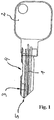
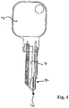
- Both Fig. 1 to 4 is assumed by a known per se key for a cylinder lock system.
- the respective key 11 has a key shank 1 and a key chalk 2.
- the key shank may have on one side a plurality of projections and recesses, which correspond with corresponding tumbler pins, which dive into the lock cylinder channel of the locking system. This has been omitted for the sake of simplicity in the figurative representations.
- the key back 3 can now according to the various examples of the Fig. 1 to 4 have at least one, extending in the key longitudinal direction recess 4.
- This recess can after Fig. 1 two bevelled edges with a flat bottom surface, a circular arc-shaped bottom surface Fig. 2 , an inclined only to the key tip oblique surface transition area after Fig. 3 or after Fig. 4 be performed as an open recess 4 on the key tip 5.
- the key 11 is not inserted correctly or not completely, like the Fig. 6a shows, or is introduced such a key 11, which is not complementary to the locking plate 6 recess. 4 has, the locking plate or the locking element 6 is in a raised position, with the result that the parting plane 8 between the cylinder housing 9 and the cylinder core 7 is locked.
- the locking plate 6 at least partially immersed in a corresponding recess or free-cutting 10 in the housing 9 a.
- the Fig. 7 shows a plan view of a lock cylinder with lock cylinder core 7 and inserted key 11th
- the key is in an end position.
- An unillustrated locking plate can completely immerse in matching key 11 in the recess 4 in the back of the key 3 and in recesses 22, which are present in the lock cylinder core 7, come to rest.
- the recess 21 in the recess 4 can be realized for example as a flat groove with inlet slope 23 or as a longitudinal groove with wedge-shaped course.
- the inclined surface 23 also facilitates the removal of the key with lifting of the locking plate 6 (see Fig. 8b ).
- the Fig. 8a shows a schematic side view of a further developed according to the invention key 11 with key crayon 2 and a plurality of formed on one side of the key shank projections and recesses, which correspond with locking pins (not shown), which dive into the lock cylinder channel of the locking system.
- the enlarged view D-D shows the cross section of the key shank 1 in the region of the recess 4.
- the recess 4 has the already explained recess 21, which corresponds to the web-like projection 20 in the locking plate 6.
- the web-like projection 20 is thus complementary to the recess 21 in the recess 4 in the back of the key, that is, only if the key 11 has the recess 20 corresponding to the web-like projection 20 recess 21 in the recess 4, a closing operation is executed, that is only then is the parting line 8 (see Fig. 5c ) Approved.
- Fig. 9 shows a cross-section of a further developed embodiment of the invention, starting from a cylinder lock system with a key inserted into the lock channel within the lock cylinder 7 key with key 2.
- the key with key shank 1 and key grain 2 is designed so that the locking plate 6 at least partially (in the illustration shown on the left and right sides) below the parting plane 8 comes to lie in not completely correct manner.
- the key and thus also the lock cylinder core 7 would be rotatable. This could be operated at least the latch of a lock and a not properly closed door can be opened.
- the area of the free-cutting 10 closely adjacent or at this area 10 immediately adjacent in the example shown on the left and right, that is both sides, in the possible direction of rotation of the lock cylinder 7 each at least one spring-biased additional Zuhaltet 100 used.
- FIG. 10 is a release of the rotation through the low-lying barrier plate 6 before.
Landscapes
- Lock And Its Accessories (AREA)
Abstract
Description
- Die Erfindung betrifft einen Schlüssel für ein Zylinderschloss-Schließsystem mit Schlüsselschaft und Schlüsselreide sowie einer Vielzahl von auf einer Seite des Schlüsselschafts ausgebildeten Vor- und Rücksprüngen, welche mit Zuhaltestiften, die in den Schließzylinderkanal des Schließsystems eintauchen, korrespondieren gemäß Oberbegriff des Anspruchs 1.
- Aus der
EP 2 360 333 A2 ist ein weiterentwickelter Schließzylinder mit Flachschlüssel hierfür vorbekannt, wobei im Schließzylinder ein Kanal eingearbeitet ist, welcher ein in Zylinderlängsrichtung verschiebliches, kolbenartiges Teil aufnimmt. Das kolbenartige Teil weist einen oder mehrere Rücksprünge auf, die eine Kugel oder einen diesbezüglichen Stift aufnehmen, um eine Sperrebene zu bilden bzw. eine Sperrebene zu blockieren. Das kolbenartige Element wird von einem Anschlag verschieblich betätigt, wobei der Anschlag an der Schlüsselreide des Flachschlüssels ausgeführt ist. Bei nicht passendem Anschlag bleibt die Sperrfunktion erhalten, so dass sich hierdurch eine ergänzende Kodiermöglichkeit ergibt. Die Konstruktion mit zusätzlichem Kanal und längsverschieblichem Kolben nebst Sperrstift oder Sperrkugel ist jedoch außerordentlich aufwendig, da sämtliche diesbezügliche Bauteile in den drehbaren Kern des Schließzylinders integriert werden müssen. - Bei dem
US-Patent 1,977,189 ist ein Schlüssel vorgesehen, der einen säbelartig gebogenen Schlüsselschaft aufweist. - Neben Rücksprüngen des Schlüssels, welche die bekannten Zuhaltungen betätigen, diesen gegenüberliegend, ist im Schlüsselschaft eine Einkerbung vorhanden, in die ein hebelartiger Fortsatz eingreift, der sich im Zylinderkern eines zugehörigen Zylinderschlosses befindet. Der Hebelarm wirkt mit einem zusätzlichen Sperrstift zusammen. Über den Hebelarm ist es demnach möglich, den zusätzlichen Sperrstift von einer Sperrposition, d.h. einer solchen Position, in der die Sperrebene blockiert ist, in eine Freigabeposition zu bewegen.
- Die Ausbildung eines verschwenkbar gelagerten Hebels zur Abtastung der Kerbe im Schlüsselschaft mit der Folge der Betätigung eines weiteren Zuhaltestifts ist jedoch technologisch schwierig und mithin kostenintensiv.
- Die
FR 2 871 497 A1 - Aus dem Vorgenannten ist es Aufgabe der Erfindung, einen weiterentwickelten Schlüssel für ein Zylinderschloss-Schließsystem mit Schlüsselschaft und Schlüsselreide sowie einer Vielzahl von auf einer Seite des Schlüsselschafts ausgebildeten Vor- und Rücksprüngen anzugeben, wobei die Vor- und Rücksprünge mit korrespondierenden Zuhaltestiften, die in den Schließzylinderkanal des Schließsystems eintauchen, zusammenwirken. Die Aufgabe besteht insbesondere darin, nicht nur eine zusätzliche Kodiermöglichkeit zu schaffen, sondern auch eine sichere, drehmomentfeste Arretierung des Zylinderkerns in der Zuhalte- bzw. Sperrposition zu gewährleisten, so dass auch mit einem erhöhten Kraftaufwand keine Drehbewegung des Zylinderkerns bzw. ein Öffnen des diesbezüglichen Schlosses ohne einen berechtigten Schlüssel erfolgen kann. Darüber hinaus soll auch bei einem einführbaren aber ansonsten nicht passendem Schlüssel eine Betätigung einer Schließfalle verhindert und der Schlüssel gefangen werden, so dass Manipulationsversuche erkennbar sind.
- Die Lösung der Aufgabe der Erfindung erfolgt durch einen Schlüssel gemäß der Merkmalskombination nach Patentanspruch 1, wobei die Unteransprüche mindestens zweckmäßige Ausgestaltungen und Weiterbildungen darstellen. Gemäß Anspruch 1 wird diesbezüglich von dem Grundgedanken ausgegangen, dass der Schlüsselrücken des Schlüssels für das spezielle Zylinderschloss-Schließsystem insbesondere im Bereich des zur Schlüsselreide gerichteten Schlüsselanschlags eine, sich in Schlüssellängsrichtung erstreckende Ausnehmung aufweist.
- Diese Ausnehmung ist in der Lage, ein komplementäres Sperrelement, insbesondere ein Sperrplättchen aufzunehmen. Das Sperrelement oder Sperrplättchen erstreckt sich quasi brückenartig über einen Teilbereich des Schließzylinderkanals. Diese Erstreckungsrichtung kann gemäß einem Ausführungsbeispiel bevorzugt 90° zur Schlüsselkanal-Längsachse betragen.
- Das Sperrelement oder Sperrplättchen stützt sich am Schließzylinderkern ab, wobei bei passendem Flachschlüssel für das Zylinderschloss-Schließsystem das Sperrplättchen bündig bezogen auf den Zylinderkern zur Lage kommt, und die Trenn- oder Sperrebene zwischen Zylinderkern und Zylindergehäuse freigegeben ist.
- In einer Ausgestaltung ist die vorerwähnte Ausnehmung im Schlüssel als Hinterschnitt realisierbar.
- Weiterhin ist eine Freifräsung im Gehäuse des Zylinderschloss-Schließsystems vorgesehen, in welche das Sperrplättchen eintaucht, wenn es durch den passenden Schlüssel angehoben ist.
- Letztendlich ist das Sperrelement oder Sperrplättchen auch nur dann bündig mit dem Zylinderkern abschließend positioniert, wenn der Schlüssel vollständig gesteckt ist.
- Ausgestaltend besitzt das Sperrelement oder Sperrplättchen eine zum Gehäuse des Zylinderschloss-Schließsystems weisende Oberflächengestalt, welche dem Krümmungsradius des Zylinderkerns entspricht.
- Alternativ können auf dem Schlüsselrücken mehrere Ausnehmungen zur Aufnahme jeweils komplementärer Sperrplättchen oder Sperrelemente vorgesehen sein.
- Erfindungsgemäß besitzt das Sperrelement oder Sperrplättchen an seiner Unterseite, welche zum Schlüssel gerichtet sind, einen stegartigen Vorsprung. Dieser stegartige Vorsprung ist komplementär zu einer Vertiefung in der Ausnehmung im Schlüsselrücken. Das heißt, nur dann, wenn der Schlüssel die zum stegartigen Vorsprung passende Vertiefung aufweist, ist ein Schließvorgang ausführbar. Hierdurch entstehen zusätzlich Kodiermöglichkeiten sowie ein höherer Kopierschutz des Schlüssels. Es ist also nicht möglich, durch ein relativ einfaches Abtragen von Material des Schlüsselrückens das Sperrplättchen in Trennebenen-Freigabeposition zu überführen, wenn ein diesbezüglich manipulierter Schlüssel gesteckt wird.
- Die Vertiefung in der Ausnehmung kann beispielsweise als Flachnut mit Einlaufschräge oder als eine Längsnut mit keilförmigem Verlauf realisiert werden.
- Abrundungen des stegartigen Vorsprunges erleichtern das Gleiten auf dem Schlüsselrücken bzw. in die Vertiefung hinein, die sich innerhalb der Ausnehmung befindet.
- Eine kinematische Umkehr mit der Ausbildung eines stegartigen Vorsprunges, der sich in der Ausnehmung im Schlüsselrücken in Richtung Sperrplättchen erstreckt und dort mit einer passenden Nut im Sperrplättchen korrespondiert, liegt im Rahmen der Erfindung.
- Bei bezogen auf das Sperrelement oder Sperrplättchen zu großen Ausnehmungen oder zu großem Hinterschnitt im Schlüssel tauchen bei versuchter Drehbewegung die Zuhaltestifte in den verbleibenden Freiraum ein, so dass hierdurch eine weitere Drehung des Schließzylinders unterbunden ist.
- Die Erfindung soll nachstehend anhand eines Ausführungsbeispiels sowie unter Zuhilfenahme von Figuren näher erläutert werden.
- Hierbei zeigen:
- Fig. 1
- eine Seitenansicht eines Flachschlüssels mit einer sich in Schlüssellängsrichtung erstreckenden Ausnehmung mit zwei schräg ausgebildeten Kantenbereichen;
- Fig. 2
- eine Darstellung eines erfindungsgemäßen Flachschlüssels mit einer Ausnehmung, die zur Schlüsselspitze hin einen schrägen Kantenbereich und zur Schlüsselreide hin einen nahezu rechtwinkligen Kanten- oder Übergangsbereich aufweist, wobei der Bodenabschnitt der Ausnehmung einen bogenförmigen Verlauf besitzt;
- Fig. 3
- eine Darstellung eines Flachschlüssels in Seitenansicht mit einer Ausnehmung im Bereich des zur Schlüsselreide gerichteten Abschnitts des Schlüsselschafts mit zur Schlüsselspitze hin gerichteten schrägen Kanten- oder Übergangsbereich und zur Schlüsselreide hin gerichteten nahezu rechtwinkligen Übergangsbereich;
- Fig. 4
- eine weitere Darstellung eines Flachschlüssels mit der erfindungsgemäßen Ausnehmung im Bereich der Schlüsselspitze auf dem Schlüsselrücken;
- Fig. 5a
- eine Seitenansicht auf ein Zylinderschloss mit eingestecktem Flachschlüssel;
- Fig. 5b
- eine Schnittdarstellung gemäß der Linie A-A nach
Fig. 5a ; - Fig. 5c
- eine Detaildarstellung des in
Fig. 5b gekennzeichneten Bereichs der Trennebene zwischen dem drehbaren Zylinderkern und dem Zylindergehäuse in dem Zustand mit freigegebener Trennebene, wobei diesbezüglich das Sperrplättchen oder das Sperrelement in der Ausnehmung des zugehörigen Schlüssels liegt; - Fig. 6a
- eine Darstellung ähnlich derjenigen nach
Fig. 5a , jedoch mit nicht vollständig gestecktem Schlüssel; - Fig. 6b
- eine Schnittdarstellung längs der Linie F-F nach
Fig. 6a ; - Fig. 6c
- eine Detaildarstellung der
Fig. 6b gemäß dem dort gekennzeichneten Bereich, wobei in der Detaildarstellung nachFig. 6c erkennbar ist, dass die Trenn- oder Sperrebene gesperrt wird, und zwar durch das angehobene Sperrelement oder Sperrplättchen, welches in eine zugehörige Ausnehmung im entsprechenden Abschnitt des Zylindergehäuses eintauchen kann; - Fig. 7
- eine Draufsicht auf einen Schließzylinder mit gestecktem Schlüssel, wobei die Ausnehmung im Schlüsselrücken nebst innerhalb der Ausnehmung vorgesehener nutartiger Vertiefung erkennbar ist. Zur besseren Übersichtlichkeit wurde das Zylindergehäuse in der Darstellung nach
Fig. 7 weggelassen; - Fig. 8a
- eine Seitenansicht eines erfindungsgemäßen Schlüssels für das Zylinderschloss-Schließsystem mit erkennbarer Ausnehmung im Schlüsselrücken; und
- Fig. 8b
- eine vergrößerte Darstellung längs der Linie D-D mit stegartigem Vorsprung 20 am Sperrplättchen 6, wobei der stegartige Vorsprung 20 komplementär ist zu einer entsprechenden Vertiefung 21 im Schlüsselrücken 3 (siehe
Fig. 7 ); - Fig. 9
- eine Querschnittsdarstellung durch ein erfindungsgemäßes Zylinderschloss mit eingeführten, das heißt gestecktem Schlüssel, wobei das Sperrelement oder Sperrplättchen in eine solche Lage kommt, bei der zumindestens Abschnitte des Sperrelementes oder Sperrplättchens unterhalb der Trennebene 8 (siehe
Fig. 5c ) liegen sowie mit zwei weiteren Zusatz-Zuhaltestiften, welche federkraftvorgespannt im Zylindergehäuse 9 angeordnet sind und - Fig. 10
- eine Darstellung ähnlich derjenigen nach
Fig. 9 , jedoch mit einer durch Pfeilrichtung angedeuteten versuchten Drehbewegung des Schlüssels, wobei der dargestellte Zusatz-Zuhaltestift aufgrund seiner Federvorspannung in einen Freiraum unterhalb der Trennebene eintritt und somit eine Weiterdrehung des Schlüssels bzw. des Schließzylinderkerns verhindert und gleichzeitig ein Herausziehen des Schlüssels aus dem Zylinderkern wirksam verhindert, das heißt den Schlüssel fängt, so dass erkennbar wird, ob und inwieweit ein Manipulationsversuch stattgefunden hat, indem ein nicht korrekter Schlüssel in den Schließzylinderkern eingeführt wurde. - Bei den
Fig. 1 bis 4 wird von einem an sich bekannten Schlüssel für ein Zylinderschloss-Schließsystem ausgegangen. Der jeweilige Schlüssel 11 weist einen Schlüsselschaft 1 sowie eine Schlüsselreide 2 auf. Der Schlüsselschaft kann auf einer Seite eine Vielzahl von Vor- und Rücksprüngen aufweisen, die mit korrespondierenden Zuhaltestiften, die in den Schließzylinderkanal des Schließsystems eintauchen, korrespondieren. Dies wurde aus Gründen der Vereinfachung bei den figürlichen Darstellungen weggelassen. - Der Schlüsselrücken 3 kann nun gemäß den verschiedenen Beispielen nach den
Fig. 1 bis 4 mindestens eine, sich in Schlüssellängsrichtung erstreckende Ausnehmung 4 besitzen. Diese Ausnehmung kann nachFig. 1 zwei Schrägkanten mit ebener Bodenfläche, eine kreisbogenförmige Bodenfläche nachFig. 2 , einen nur zur Schlüsselspitze gerichteten Schrägflächen-Übergangsbereich nachFig. 3 oder nachFig. 4 als offene Ausnehmung 4 an der Schlüsselspitze 5 ausgeführt werden. - Anhand der
Fig. 5 und 6 wird die Wirkung der erfindungsgemäßen Lösung im Sinne der Wechselwirkung zwischen Ausnehmung 4 und Sperrplättchen oder Sperrelement 6 deutlich. - Bei gestecktem Schlüssel 11 gemäß
Fig. 5a befindet sich dieser mit seinem Schlüsselanschlag am äußeren Ende des Zylinderkerns 7. - In diesem Zustand liegt die in der
Fig. 6a gezeigte Ausnehmung 4 mit schräger Bodenfläche so im Bereich des Zylinderkerns, dass das Sperrplättchen 6 mit seiner Oberkante mit der Innenoberfläche des Zylinderkerns in eine bündige Lage kommt, so dass die Trennebene 8 freigegeben ist. - Wird hingegen der Schlüssel 11 nicht korrekt oder nicht vollständig eingesteckt, wie dies die
Fig. 6a zeigt, oder wird ein solcher Schlüssel 11 eingeführt, der keine zum Sperrplättchen 6 komplementäre Ausnehmung 4 besitzt, befindet sich das Sperrplättchen oder das Sperrelement 6 in einer angehobenen Stellung mit der Folge, dass die Trennebene 8 zwischen dem Zylindergehäuse 9 und dem Zylinderkern 7 gesperrt ist. Insofern taucht das Sperrplättchen 6 mindestens teilweise in eine entsprechende Ausnehmung bzw. Freifräsung 10 im Gehäuse 9 ein. - Die
Fig. 7 zeigt eine Draufsicht auf einen Schließzylinder mit Schließzylinderkern 7 und gestecktem Schlüssel 11. - Der Schlüssel befindet sich in einer Endlageposition.
- Ein nicht dargestelltes Sperrplättchen kann bei passendem Schlüssel 11 vollständig in die Ausnehmung 4 im Schlüsselrücken 3 eintauchen und in Rücksprünge 22, die im Schließzylinderkern 7 vorhanden sind, zur Anlage kommen.
- Dies ist jedoch nur dann möglich, wenn der stegartige Vorsprung 20 (siehe
Fig. 8b ) vollständig in eine komplementäre Vertiefung 21 in der Ausnehmung 4 eintaucht. - Die Vertiefung 21 in der Ausnehmung 4 kann beispielsweise als Flachnut mit Einlaufschräge 23 oder als Längsnut mit keilförmigem Verlauf realisiert werden.
- Die Schrägfläche 23 erleichtert darüber hinaus das Abziehen des Schlüssels mit Anheben des Sperrplättchens 6 (siehe
Fig. 8b ).
DieFig. 8a zeigt eine prinzipielle Seitenansicht eines erfindungsgemäß weitergebildeten Schlüssels 11 mit Schlüsselreide 2 sowie einer Vielzahl von auf einer Seite des Schlüsselschaftes ausgebildeten Vor- und Rücksprüngen, welche mit Zuhaltestiften (nicht gezeigt), die in den Schließzylinderkanal des Schließsystems eintauchen, korrespondieren. - Die vergrößerte Darstellung D-D lässt den Querschnitt des Schlüsselschaftes 1 im Bereich der Ausnehmung 4 erkennen.
- Die Ausnehmung 4 besitzt die bereits erläuterte Vertiefung 21, die mit dem stegartigen Vorsprung 20 im Sperrplättchen 6 korrespondiert.
- Der stegartige Vorsprung 20 ist also komplementär mit der Vertiefung 21 in der Ausnehmung 4 im Schlüsselrücken, das heißt nur dann, wenn der Schlüssel 11 die zum stegartigen Vorsprung 20 passende Vertiefung 21 in der Ausnehmung 4 besitzt, ist ein Schließvorgang ausführbar, das heißt nur dann wird die Trennebene 8 (siehe
Fig. 5c ) freigegeben. - Die
Fig. 9 zeigt einen Querschnitt einer weitergebildeten Ausführungsform der Erfindung ausgehend von einem Zylinderschloss-Schließsystem mit einem in den Schließkanal innerhalb des Schließzylinderkerns 7 eingeführten Schlüssel mit Schlüsselreide 2. - Der Schlüssel mit Schlüsselschaft 1 und Schlüsselreide 2 ist dabei so ausgebildet, dass in nicht völlig korrekter Weise das Sperrplättchen 6 mindestens teilweise (in der gezeigten Darstellung links- und rechtsseitig) unterhalb der Trennebene 8 zu liegen kommt.
- Ohne weitere Maßnahmen wäre hier der Schlüssel und damit auch der Schließzylinderkern 7 drehbar. Damit könnte zumindest die Schließfalle eines Schlosses betätigt und eine nicht korrekt verschlossene Tür geöffnet werden.
- Derartige Manipulationen gilt es mit der erfindungsgemäßen Weiterbildung im Rahmen des hier geschilderten Ausführungsbeispieles zu verhindern.
- Diesbezüglich ist im Zylindergehäuse 9, dem Bereich der Freifräsung 10 eng benachbart bzw. an diesem Bereich 10 unmittelbar angrenzend im gezeigten Beispiel links- und rechtsseitig, das heißt beidseitig, in möglicher Drehrichtung des Schließzylinders 7 jeweils mindestens ein federkraftvorgespannter Zusatz-Zuhaltestift 100 eingesetzt.
- Bei der Ausgangssituation gemäß
Figur 9 und erfolgter Drehung des Schlüssels gemäß Pfeilrichtung nachFigur 10 liegt eine Freigabe des Drehweges durch das tiefliegende Sperrplättchen 6 vor. - Da jedoch das Sperrplättchen 6 mit seiner Oberfläche nicht bündig mit der Oberfläche des Zylinderkerns 7 abschließt und insofern mindestens Abschnitte des Sperrplättchens unterhalb der Trennebene 8 liegen, kann der Zusatz-Zuhaltestift 100 in den diesbezüglichen, in der Figur erkennbaren Freiraum eintauchen und eine weitere Drehbewegung des Schlüssels respektive des Zylinderkerns 7 verhindern.
- Da es sich um eine quasi punktförmige Zuhaltung handelt und das Sperrplättchen in einer räumlich begrenzten Ausnehmung gemäß der bereits erfolgten Schilderung aufgenommen wird bzw. dort eintaucht sind auch die in der
Figur 10 gezeigten Freiräume 101 in Längsrichtung des Zylinderkerns 7 begrenzt. Die Folge ist, dass der Schlüssel aus der erreichten Position nicht mehr weitergedreht oder zurückgedreht werden kann. Ebenso wenig ist es möglich, den Schlüssel abzuziehen. - Wird ein derartiger Schlüssel, welcher nicht mehr beweglich ist, im entsprechenden Schloss entdeckt, handelt es sich mit großer Wahrscheinlichkeit um einen Manipulationsversuch. Hiernach können geeignete Maßnahmen ergriffen werden.
Claims (10)
- Schlüssel für ein Zylinderschloss-Schließsystem mit Schlüsselschaft (1) und Schlüsselreide (2) sowie einer Vielzahl von auf einer Seite des Schlüsselschafts (1) ausgebildeten Vor- und Rücksprüngen, welche mit Zuhaltestiften, die in den Schließzylinderkanal des Schließsystems eintauchen, korrespondieren,
dadurch gekennzeichnet, dass
der Schlüsselrücken (3) mindestens eine sich in Schlüssellängsrichtung erstreckende Ausnehmung (4) aufweist, welche ein der Ausnehmung (4) komplementäres Sperrelement oder Sperrplättchen (6) aufnehmen kann und das Sperrelement oder Sperrplättchen (6) sich brückenartig über einen Teilbereich des Schließzylinderkanals erstreckend am Schließzylinderkern (7) abstützt, wobei bei passendem Schlüssel (11) für das Zylinderschloss-Schließsystem das Sperrelement oder Sperrplättchen (6) bündig mit dem Zylinderkern (7) abschließt und die Trennebene (8) zwischen Zylinderkern (7) und Zylindergehäuse (9) freigegeben ist, wobei das Sperrelement oder Sperrplättchen (6) an seiner Unterseite einen stegartigen Vorsprung (20) besitzt, welcher komplementär zu einer Vertiefung (21) in der Ausnehmung (4) im Schlüsselrücken (3) ist. - Schlüssel nach Anspruch 1,
dadurch gekennzeichnet, dass
die Ausnehmung (4) im Schlüssel (11) als Hinterschnitt realisiert ist. - Schlüssel nach Anspruch 1 oder 2,
dadurch gekennzeichnet, dass
im Gehäuse (1) des Zylinderschloss-Schließsystems eine Freifräsung (10) ausgebildet ist, in welche das Sperrelement (6) im durch den Schlüssel (11) angehobenen Zustand eintaucht. - Schlüssel nach einem der vorangegangenen Ansprüche,
dadurch gekennzeichnet, dass
das Sperrelement (6) nur im vollständig gesteckten Zustand des Schlüssels (11) bündig mit dem Zylinderkern (7) abschließt. - Schlüssel nach einem der vorangegangenen Ansprüche,
dadurch gekennzeichnet, dass
das Sperrelement (6) eine zum Gehäuse (9) des Zylinderschloss-Schließsystems weisende Oberflächengestalt aufweist, welche dem Krümmungsradius des Zylinderkerns (7) entspricht oder diesem weitgehend angenähert ist. - Schlüssel nach einem der vorangegangenen Ansprüche,
dadurch gekennzeichnet, dass
auf dem Schlüsselrücken (3) mehrere Ausnehmungen (4) zur Aufnahme jeweils komplementärer Sperrelemente (6) vorgesehen sind. - Schlüssel nach einem der vorangegangenen Ansprüche,
dadurch gekennzeichnet, dass
bei bezogen auf das Sperrelement (6) zu großer Ausnehmung (4) oder zu großem Hinterschnitt im Schlüssel (11) bei versuchter Drehbewegung in den verbleibenden Freiraum Zuhaltestifte eintauchen und eine weitere Drehung des Schließzylinders unterbinden. - Schlüssel nach einem der vorangegangenen Ansprüche,
dadurch gekennzeichnet, dass
das Sperrelement oder Sperrplättchen (6) aus einem Material mit bezogen auf das Material des Schlüssels oder des Zylinderkerns (7) anderen Eigenschaften, insbesondere hinsichtlich der Härte besteht oder ein MIM-gefertigtes Teil ist. - Schlüssel nach einem der vorangegangenen Ansprüche,
dadurch gekennzeichnet, dass
die mindestens eine Ausnehmung (4) im Bereich des zur Schlüsselreide (2) gerichteten Schlüsselanschlags vorgesehen ist. - Schlüssel nach Anspruch 3 und 7,
dadurch gekennzeichnet, dass
im Zylindergehäuse (9), dem Bereich der Freifräsung (10), ein- und/oder beidseitig in Drehrichtung des Schließzylinders (7) benachbart, in Richtung Schließzylinderkern mindestens ein federkraftvorgespannter Zusatz-Zuhaltestift (100) vorgesehen ist, welcher eine weitere Drehung des Schließzylinderkerns (7) verhindert, wenn das Sperrplättchen (6) mindestens teilweise unterhalb der Trennebene (8) zu liegen kommt.
Applications Claiming Priority (1)
| Application Number | Priority Date | Filing Date | Title |
|---|---|---|---|
| DE102016122256.9A DE102016122256A1 (de) | 2016-11-18 | 2016-11-18 | Schlüssel für ein Zylinderschloss-Schließsystem mit Schlüsselschaft und Schlüsselreide |
Publications (2)
| Publication Number | Publication Date |
|---|---|
| EP3323964A1 true EP3323964A1 (de) | 2018-05-23 |
| EP3323964B1 EP3323964B1 (de) | 2020-03-04 |
Family
ID=60268293
Family Applications (1)
| Application Number | Title | Priority Date | Filing Date |
|---|---|---|---|
| EP17200242.0A Active EP3323964B1 (de) | 2016-11-18 | 2017-11-07 | Zylinderschloss-schliesssystem mit einem schlüssel |
Country Status (3)
| Country | Link |
|---|---|
| EP (1) | EP3323964B1 (de) |
| DE (1) | DE102016122256A1 (de) |
| ES (1) | ES2796376T3 (de) |
Citations (4)
| Publication number | Priority date | Publication date | Assignee | Title |
|---|---|---|---|---|
| US1835725A (en) * | 1927-05-27 | 1931-12-08 | Yale & Towne Mfg Co | Cylinder lock |
| EP0712980A1 (de) * | 1994-11-15 | 1996-05-22 | EVVA - Werk Spezialerzeugung von Zylinder-und Sicherheitsschlössern Gesellschaft m.b.H. & Co. Kommanditgesellschaft | Zylinderschloss mit Zylinderkern und Zylindergehäuse |
| WO2006066019A2 (en) * | 2004-12-14 | 2006-06-22 | Stanley Security Solutions, Inc. | Key core |
| EP2644809A1 (de) * | 2012-03-28 | 2013-10-02 | Assa Abloy Aube Anjou | Sicherheitszylinder mit Arretierungen und entsprechendem Schlüssel |
Family Cites Families (7)
| Publication number | Priority date | Publication date | Assignee | Title |
|---|---|---|---|---|
| US1977189A (en) | 1933-12-04 | 1934-10-16 | Ivar G Larson | Lock |
| DE963123C (de) * | 1954-06-15 | 1957-05-02 | Ladislao Jose Biro | Sicherheitsschloss |
| AT2738U1 (de) * | 1998-04-09 | 1999-03-25 | Kaba Gege Gmbh | Schliesszylinder mit schlüssel |
| DE10049780A1 (de) * | 2000-10-09 | 2002-04-18 | Winkhaus Fa August | Schlüssel für einen Profilschließzylinder und Profilschließzylinder |
| FR2820776B3 (fr) * | 2001-02-15 | 2002-12-27 | Evva Werke | Serrure a cylindre perfectionnee et cle plate pour une telle serrure |
| FR2871497B1 (fr) | 2004-06-10 | 2007-11-30 | Deny Fontaine Soc Par Actions | Cle de securite pour cylindre de serrure |
| GB201002548D0 (en) | 2010-02-15 | 2010-03-31 | Banham Patent Locks Ltd | Improved lock cylinder |
-
2016
- 2016-11-18 DE DE102016122256.9A patent/DE102016122256A1/de not_active Ceased
-
2017
- 2017-11-07 ES ES17200242T patent/ES2796376T3/es active Active
- 2017-11-07 EP EP17200242.0A patent/EP3323964B1/de active Active
Patent Citations (4)
| Publication number | Priority date | Publication date | Assignee | Title |
|---|---|---|---|---|
| US1835725A (en) * | 1927-05-27 | 1931-12-08 | Yale & Towne Mfg Co | Cylinder lock |
| EP0712980A1 (de) * | 1994-11-15 | 1996-05-22 | EVVA - Werk Spezialerzeugung von Zylinder-und Sicherheitsschlössern Gesellschaft m.b.H. & Co. Kommanditgesellschaft | Zylinderschloss mit Zylinderkern und Zylindergehäuse |
| WO2006066019A2 (en) * | 2004-12-14 | 2006-06-22 | Stanley Security Solutions, Inc. | Key core |
| EP2644809A1 (de) * | 2012-03-28 | 2013-10-02 | Assa Abloy Aube Anjou | Sicherheitszylinder mit Arretierungen und entsprechendem Schlüssel |
Also Published As
| Publication number | Publication date |
|---|---|
| ES2796376T3 (es) | 2020-11-26 |
| DE102016122256A1 (de) | 2018-05-24 |
| EP3323964B1 (de) | 2020-03-04 |
Similar Documents
| Publication | Publication Date | Title |
|---|---|---|
| DE4035934C2 (de) | Aus Schlüssel und Schließzylinder bestehende Schließvorrichtung | |
| DE2631674A1 (de) | Schloss und schluessel | |
| DE102004023608A1 (de) | Schloss | |
| DE69418997T2 (de) | Zuhaltungsschloss mit veränderbarer Kombination für Tresortüren | |
| DE69906312T2 (de) | Sperrvorrichtung mit selektiver verriegelung | |
| DE19549053A1 (de) | Sicherheitsschloß mit einem Schließzylinder und einem Schlüssel mit flachem Schaft | |
| DE102009044170A1 (de) | Schließvorrichtung bestehend aus einem Schließzylinder und einem dazu passenden Schlüssel | |
| DE2923972C2 (de) | Versperrbarer Schieber für Reißverschlüsse | |
| DE69207320T2 (de) | Verbesserter Schloss mit einer Einrichtung zwecks Öffnen im Notfall | |
| DE60025560T2 (de) | Schloss | |
| DE102013103790B4 (de) | Schließzylinder | |
| AT404857B (de) | Zylinderschloss mit zylinderkern und zylindergehäuse sowie flachschlüssel | |
| DE2743769A1 (de) | Schloss und codierter schluessel zur betaetigung des schlosses | |
| DE102009044207B4 (de) | Schließzylinder mit zugehörigem Schlüssel und Sperrrippenabtastung | |
| EP3323964B1 (de) | Zylinderschloss-schliesssystem mit einem schlüssel | |
| DE3533366C2 (de) | ||
| EP0756052B1 (de) | Schliesszylinder mit Stiftzuhaltungen sowie Schlüssel für einen Schliesszylinder mit Stiftzuhaltungen | |
| DE602004006061T2 (de) | Panik-Stangengriff für Einsteckschlösser | |
| DE2558249A1 (de) | Mittels eines permanentmagnet- schluessels betaetigbares drehzylinderschloss | |
| DE102015007961A1 (de) | Schlüssel für ein Zylinderschloss-Schließsystem mit Schlüsselschaft und Schlüsselreide | |
| DE1910849A1 (de) | Zylinderschloss | |
| DE102011000576A1 (de) | Schloss für eine Tür oder Dergleichen sowie Handwerkzeug für ein Schloss | |
| EP1785558B1 (de) | Schloss, insbesondere Tresorschloss | |
| EP0447354B1 (de) | Schloss mit Segmenteinsatz | |
| DE29722567U1 (de) | Stiftzylinderschloß |
Legal Events
| Date | Code | Title | Description |
|---|---|---|---|
| PUAI | Public reference made under article 153(3) epc to a published international application that has entered the european phase |
Free format text: ORIGINAL CODE: 0009012 |
|
| STAA | Information on the status of an ep patent application or granted ep patent |
Free format text: STATUS: THE APPLICATION HAS BEEN PUBLISHED |
|
| AK | Designated contracting states |
Kind code of ref document: A1 Designated state(s): AL AT BE BG CH CY CZ DE DK EE ES FI FR GB GR HR HU IE IS IT LI LT LU LV MC MK MT NL NO PL PT RO RS SE SI SK SM TR |
|
| AX | Request for extension of the european patent |
Extension state: BA ME |
|
| STAA | Information on the status of an ep patent application or granted ep patent |
Free format text: STATUS: REQUEST FOR EXAMINATION WAS MADE |
|
| 17P | Request for examination filed |
Effective date: 20180627 |
|
| RBV | Designated contracting states (corrected) |
Designated state(s): AL AT BE BG CH CY CZ DE DK EE ES FI FR GB GR HR HU IE IS IT LI LT LU LV MC MK MT NL NO PL PT RO RS SE SI SK SM TR |
|
| GRAP | Despatch of communication of intention to grant a patent |
Free format text: ORIGINAL CODE: EPIDOSNIGR1 |
|
| STAA | Information on the status of an ep patent application or granted ep patent |
Free format text: STATUS: GRANT OF PATENT IS INTENDED |
|
| INTG | Intention to grant announced |
Effective date: 20190918 |
|
| GRAS | Grant fee paid |
Free format text: ORIGINAL CODE: EPIDOSNIGR3 |
|
| GRAA | (expected) grant |
Free format text: ORIGINAL CODE: 0009210 |
|
| STAA | Information on the status of an ep patent application or granted ep patent |
Free format text: STATUS: THE PATENT HAS BEEN GRANTED |
|
| AK | Designated contracting states |
Kind code of ref document: B1 Designated state(s): AL AT BE BG CH CY CZ DE DK EE ES FI FR GB GR HR HU IE IS IT LI LT LU LV MC MK MT NL NO PL PT RO RS SE SI SK SM TR |
|
| REG | Reference to a national code |
Ref country code: GB Ref legal event code: FG4D Free format text: NOT ENGLISH |
|
| REG | Reference to a national code |
Ref country code: CH Ref legal event code: EP |
|
| REG | Reference to a national code |
Ref country code: AT Ref legal event code: REF Ref document number: 1240528 Country of ref document: AT Kind code of ref document: T Effective date: 20200315 |
|
| REG | Reference to a national code |
Ref country code: DE Ref legal event code: R096 Ref document number: 502017004074 Country of ref document: DE |
|
| REG | Reference to a national code |
Ref country code: IE Ref legal event code: FG4D Free format text: LANGUAGE OF EP DOCUMENT: GERMAN |
|
| REG | Reference to a national code |
Ref country code: NL Ref legal event code: FP |
|
| PG25 | Lapsed in a contracting state [announced via postgrant information from national office to epo] |
Ref country code: NO Free format text: LAPSE BECAUSE OF FAILURE TO SUBMIT A TRANSLATION OF THE DESCRIPTION OR TO PAY THE FEE WITHIN THE PRESCRIBED TIME-LIMIT Effective date: 20200604 Ref country code: RS Free format text: LAPSE BECAUSE OF FAILURE TO SUBMIT A TRANSLATION OF THE DESCRIPTION OR TO PAY THE FEE WITHIN THE PRESCRIBED TIME-LIMIT Effective date: 20200304 Ref country code: FI Free format text: LAPSE BECAUSE OF FAILURE TO SUBMIT A TRANSLATION OF THE DESCRIPTION OR TO PAY THE FEE WITHIN THE PRESCRIBED TIME-LIMIT Effective date: 20200304 |
|
| PG25 | Lapsed in a contracting state [announced via postgrant information from national office to epo] |
Ref country code: GR Free format text: LAPSE BECAUSE OF FAILURE TO SUBMIT A TRANSLATION OF THE DESCRIPTION OR TO PAY THE FEE WITHIN THE PRESCRIBED TIME-LIMIT Effective date: 20200605 Ref country code: BG Free format text: LAPSE BECAUSE OF FAILURE TO SUBMIT A TRANSLATION OF THE DESCRIPTION OR TO PAY THE FEE WITHIN THE PRESCRIBED TIME-LIMIT Effective date: 20200604 Ref country code: HR Free format text: LAPSE BECAUSE OF FAILURE TO SUBMIT A TRANSLATION OF THE DESCRIPTION OR TO PAY THE FEE WITHIN THE PRESCRIBED TIME-LIMIT Effective date: 20200304 Ref country code: SE Free format text: LAPSE BECAUSE OF FAILURE TO SUBMIT A TRANSLATION OF THE DESCRIPTION OR TO PAY THE FEE WITHIN THE PRESCRIBED TIME-LIMIT Effective date: 20200304 Ref country code: LV Free format text: LAPSE BECAUSE OF FAILURE TO SUBMIT A TRANSLATION OF THE DESCRIPTION OR TO PAY THE FEE WITHIN THE PRESCRIBED TIME-LIMIT Effective date: 20200304 |
|
| REG | Reference to a national code |
Ref country code: LT Ref legal event code: MG4D |
|
| PG25 | Lapsed in a contracting state [announced via postgrant information from national office to epo] |
Ref country code: PT Free format text: LAPSE BECAUSE OF FAILURE TO SUBMIT A TRANSLATION OF THE DESCRIPTION OR TO PAY THE FEE WITHIN THE PRESCRIBED TIME-LIMIT Effective date: 20200729 Ref country code: IS Free format text: LAPSE BECAUSE OF FAILURE TO SUBMIT A TRANSLATION OF THE DESCRIPTION OR TO PAY THE FEE WITHIN THE PRESCRIBED TIME-LIMIT Effective date: 20200704 Ref country code: SK Free format text: LAPSE BECAUSE OF FAILURE TO SUBMIT A TRANSLATION OF THE DESCRIPTION OR TO PAY THE FEE WITHIN THE PRESCRIBED TIME-LIMIT Effective date: 20200304 Ref country code: SM Free format text: LAPSE BECAUSE OF FAILURE TO SUBMIT A TRANSLATION OF THE DESCRIPTION OR TO PAY THE FEE WITHIN THE PRESCRIBED TIME-LIMIT Effective date: 20200304 Ref country code: LT Free format text: LAPSE BECAUSE OF FAILURE TO SUBMIT A TRANSLATION OF THE DESCRIPTION OR TO PAY THE FEE WITHIN THE PRESCRIBED TIME-LIMIT Effective date: 20200304 Ref country code: CZ Free format text: LAPSE BECAUSE OF FAILURE TO SUBMIT A TRANSLATION OF THE DESCRIPTION OR TO PAY THE FEE WITHIN THE PRESCRIBED TIME-LIMIT Effective date: 20200304 Ref country code: RO Free format text: LAPSE BECAUSE OF FAILURE TO SUBMIT A TRANSLATION OF THE DESCRIPTION OR TO PAY THE FEE WITHIN THE PRESCRIBED TIME-LIMIT Effective date: 20200304 Ref country code: EE Free format text: LAPSE BECAUSE OF FAILURE TO SUBMIT A TRANSLATION OF THE DESCRIPTION OR TO PAY THE FEE WITHIN THE PRESCRIBED TIME-LIMIT Effective date: 20200304 |
|
| REG | Reference to a national code |
Ref country code: ES Ref legal event code: FG2A Ref document number: 2796376 Country of ref document: ES Kind code of ref document: T3 Effective date: 20201126 |
|
| REG | Reference to a national code |
Ref country code: DE Ref legal event code: R097 Ref document number: 502017004074 Country of ref document: DE |
|
| PLBE | No opposition filed within time limit |
Free format text: ORIGINAL CODE: 0009261 |
|
| STAA | Information on the status of an ep patent application or granted ep patent |
Free format text: STATUS: NO OPPOSITION FILED WITHIN TIME LIMIT |
|
| PG25 | Lapsed in a contracting state [announced via postgrant information from national office to epo] |
Ref country code: DK Free format text: LAPSE BECAUSE OF FAILURE TO SUBMIT A TRANSLATION OF THE DESCRIPTION OR TO PAY THE FEE WITHIN THE PRESCRIBED TIME-LIMIT Effective date: 20200304 |
|
| 26N | No opposition filed |
Effective date: 20201207 |
|
| PG25 | Lapsed in a contracting state [announced via postgrant information from national office to epo] |
Ref country code: PL Free format text: LAPSE BECAUSE OF FAILURE TO SUBMIT A TRANSLATION OF THE DESCRIPTION OR TO PAY THE FEE WITHIN THE PRESCRIBED TIME-LIMIT Effective date: 20200304 Ref country code: SI Free format text: LAPSE BECAUSE OF FAILURE TO SUBMIT A TRANSLATION OF THE DESCRIPTION OR TO PAY THE FEE WITHIN THE PRESCRIBED TIME-LIMIT Effective date: 20200304 |
|
| PG25 | Lapsed in a contracting state [announced via postgrant information from national office to epo] |
Ref country code: MC Free format text: LAPSE BECAUSE OF FAILURE TO SUBMIT A TRANSLATION OF THE DESCRIPTION OR TO PAY THE FEE WITHIN THE PRESCRIBED TIME-LIMIT Effective date: 20200304 |
|
| PG25 | Lapsed in a contracting state [announced via postgrant information from national office to epo] |
Ref country code: LU Free format text: LAPSE BECAUSE OF NON-PAYMENT OF DUE FEES Effective date: 20201107 |
|
| PG25 | Lapsed in a contracting state [announced via postgrant information from national office to epo] |
Ref country code: IE Free format text: LAPSE BECAUSE OF NON-PAYMENT OF DUE FEES Effective date: 20201107 |
|
| PG25 | Lapsed in a contracting state [announced via postgrant information from national office to epo] |
Ref country code: TR Free format text: LAPSE BECAUSE OF FAILURE TO SUBMIT A TRANSLATION OF THE DESCRIPTION OR TO PAY THE FEE WITHIN THE PRESCRIBED TIME-LIMIT Effective date: 20200304 Ref country code: MT Free format text: LAPSE BECAUSE OF FAILURE TO SUBMIT A TRANSLATION OF THE DESCRIPTION OR TO PAY THE FEE WITHIN THE PRESCRIBED TIME-LIMIT Effective date: 20200304 Ref country code: CY Free format text: LAPSE BECAUSE OF FAILURE TO SUBMIT A TRANSLATION OF THE DESCRIPTION OR TO PAY THE FEE WITHIN THE PRESCRIBED TIME-LIMIT Effective date: 20200304 |
|
| PG25 | Lapsed in a contracting state [announced via postgrant information from national office to epo] |
Ref country code: MK Free format text: LAPSE BECAUSE OF FAILURE TO SUBMIT A TRANSLATION OF THE DESCRIPTION OR TO PAY THE FEE WITHIN THE PRESCRIBED TIME-LIMIT Effective date: 20200304 Ref country code: AL Free format text: LAPSE BECAUSE OF FAILURE TO SUBMIT A TRANSLATION OF THE DESCRIPTION OR TO PAY THE FEE WITHIN THE PRESCRIBED TIME-LIMIT Effective date: 20200304 |
|
| PGFP | Annual fee paid to national office [announced via postgrant information from national office to epo] |
Ref country code: NL Payment date: 20221124 Year of fee payment: 6 Ref country code: IT Payment date: 20221122 Year of fee payment: 6 Ref country code: GB Payment date: 20221122 Year of fee payment: 6 Ref country code: FR Payment date: 20221122 Year of fee payment: 6 Ref country code: ES Payment date: 20221212 Year of fee payment: 6 Ref country code: AT Payment date: 20221118 Year of fee payment: 6 Ref country code: DE Payment date: 20220530 Year of fee payment: 6 |
|
| PGFP | Annual fee paid to national office [announced via postgrant information from national office to epo] |
Ref country code: CH Payment date: 20221123 Year of fee payment: 6 Ref country code: BE Payment date: 20221124 Year of fee payment: 6 |
|
| P01 | Opt-out of the competence of the unified patent court (upc) registered |
Effective date: 20230621 |
|
| REG | Reference to a national code |
Ref country code: DE Ref legal event code: R119 Ref document number: 502017004074 Country of ref document: DE |
|
| REG | Reference to a national code |
Ref country code: CH Ref legal event code: PL |
|
| REG | Reference to a national code |
Ref country code: NL Ref legal event code: MM Effective date: 20231201 |
|
| REG | Reference to a national code |
Ref country code: AT Ref legal event code: MM01 Ref document number: 1240528 Country of ref document: AT Kind code of ref document: T Effective date: 20231107 |
|
| PG25 | Lapsed in a contracting state [announced via postgrant information from national office to epo] |
Ref country code: CH Free format text: LAPSE BECAUSE OF NON-PAYMENT OF DUE FEES Effective date: 20231130 |
|
| PG25 | Lapsed in a contracting state [announced via postgrant information from national office to epo] |
Ref country code: AT Free format text: LAPSE BECAUSE OF NON-PAYMENT OF DUE FEES Effective date: 20231107 |
|
| GBPC | Gb: european patent ceased through non-payment of renewal fee |
Effective date: 20231107 |
|
| PG25 | Lapsed in a contracting state [announced via postgrant information from national office to epo] |
Ref country code: CH Free format text: LAPSE BECAUSE OF NON-PAYMENT OF DUE FEES Effective date: 20231130 Ref country code: AT Free format text: LAPSE BECAUSE OF NON-PAYMENT OF DUE FEES Effective date: 20231107 |
|
| REG | Reference to a national code |
Ref country code: BE Ref legal event code: MM Effective date: 20231130 |
|
| PG25 | Lapsed in a contracting state [announced via postgrant information from national office to epo] |
Ref country code: NL Free format text: LAPSE BECAUSE OF NON-PAYMENT OF DUE FEES Effective date: 20231201 |
|
| PG25 | Lapsed in a contracting state [announced via postgrant information from national office to epo] |
Ref country code: NL Free format text: LAPSE BECAUSE OF NON-PAYMENT OF DUE FEES Effective date: 20231201 |
|
| PG25 | Lapsed in a contracting state [announced via postgrant information from national office to epo] |
Ref country code: DE Free format text: LAPSE BECAUSE OF NON-PAYMENT OF DUE FEES Effective date: 20240601 |
|
| PG25 | Lapsed in a contracting state [announced via postgrant information from national office to epo] |
Ref country code: GB Free format text: LAPSE BECAUSE OF NON-PAYMENT OF DUE FEES Effective date: 20231107 |
|
| PG25 | Lapsed in a contracting state [announced via postgrant information from national office to epo] |
Ref country code: BE Free format text: LAPSE BECAUSE OF NON-PAYMENT OF DUE FEES Effective date: 20231130 |
|
| PG25 | Lapsed in a contracting state [announced via postgrant information from national office to epo] |
Ref country code: FR Free format text: LAPSE BECAUSE OF NON-PAYMENT OF DUE FEES Effective date: 20231130 |
|
| PG25 | Lapsed in a contracting state [announced via postgrant information from national office to epo] |
Ref country code: GB Free format text: LAPSE BECAUSE OF NON-PAYMENT OF DUE FEES Effective date: 20231107 Ref country code: FR Free format text: LAPSE BECAUSE OF NON-PAYMENT OF DUE FEES Effective date: 20231130 Ref country code: DE Free format text: LAPSE BECAUSE OF NON-PAYMENT OF DUE FEES Effective date: 20240601 Ref country code: BE Free format text: LAPSE BECAUSE OF NON-PAYMENT OF DUE FEES Effective date: 20231130 |
|
| PG25 | Lapsed in a contracting state [announced via postgrant information from national office to epo] |
Ref country code: IT Free format text: LAPSE BECAUSE OF NON-PAYMENT OF DUE FEES Effective date: 20231107 |
|
| PG25 | Lapsed in a contracting state [announced via postgrant information from national office to epo] |
Ref country code: IT Free format text: LAPSE BECAUSE OF NON-PAYMENT OF DUE FEES Effective date: 20231107 |
|
| REG | Reference to a national code |
Ref country code: ES Ref legal event code: FD2A Effective date: 20250102 |
|
| PG25 | Lapsed in a contracting state [announced via postgrant information from national office to epo] |
Ref country code: ES Free format text: LAPSE BECAUSE OF NON-PAYMENT OF DUE FEES Effective date: 20231108 |
|
| PG25 | Lapsed in a contracting state [announced via postgrant information from national office to epo] |
Ref country code: ES Free format text: LAPSE BECAUSE OF NON-PAYMENT OF DUE FEES Effective date: 20231108 |