EP3323980A1 - Gasturbine - Google Patents
Gasturbine Download PDFInfo
- Publication number
- EP3323980A1 EP3323980A1 EP17201894.7A EP17201894A EP3323980A1 EP 3323980 A1 EP3323980 A1 EP 3323980A1 EP 17201894 A EP17201894 A EP 17201894A EP 3323980 A1 EP3323980 A1 EP 3323980A1
- Authority
- EP
- European Patent Office
- Prior art keywords
- inner ring
- gas turbine
- damping
- clamping member
- tie rod
- Prior art date
- Legal status (The legal status is an assumption and is not a legal conclusion. Google has not performed a legal analysis and makes no representation as to the accuracy of the status listed.)
- Granted
Links
Images




Classifications
-
- F—MECHANICAL ENGINEERING; LIGHTING; HEATING; WEAPONS; BLASTING
- F01—MACHINES OR ENGINES IN GENERAL; ENGINE PLANTS IN GENERAL; STEAM ENGINES
- F01D—NON-POSITIVE DISPLACEMENT MACHINES OR ENGINES, e.g. STEAM TURBINES
- F01D5/00—Blades; Blade-carrying members; Heating, heat-insulating, cooling or antivibration means on the blades or the members
- F01D5/02—Blade-carrying members, e.g. rotors
- F01D5/10—Anti- vibration means
-
- F—MECHANICAL ENGINEERING; LIGHTING; HEATING; WEAPONS; BLASTING
- F01—MACHINES OR ENGINES IN GENERAL; ENGINE PLANTS IN GENERAL; STEAM ENGINES
- F01D—NON-POSITIVE DISPLACEMENT MACHINES OR ENGINES, e.g. STEAM TURBINES
- F01D25/00—Component parts, details, or accessories, not provided for in, or of interest apart from, other groups
- F01D25/08—Cooling; Heating; Heat-insulation
- F01D25/12—Cooling
-
- F—MECHANICAL ENGINEERING; LIGHTING; HEATING; WEAPONS; BLASTING
- F01—MACHINES OR ENGINES IN GENERAL; ENGINE PLANTS IN GENERAL; STEAM ENGINES
- F01D—NON-POSITIVE DISPLACEMENT MACHINES OR ENGINES, e.g. STEAM TURBINES
- F01D25/00—Component parts, details, or accessories, not provided for in, or of interest apart from, other groups
- F01D25/16—Arrangement of bearings; Supporting or mounting bearings in casings
- F01D25/162—Bearing supports
- F01D25/164—Flexible supports; Vibration damping means associated with the bearing
-
- F—MECHANICAL ENGINEERING; LIGHTING; HEATING; WEAPONS; BLASTING
- F01—MACHINES OR ENGINES IN GENERAL; ENGINE PLANTS IN GENERAL; STEAM ENGINES
- F01D—NON-POSITIVE DISPLACEMENT MACHINES OR ENGINES, e.g. STEAM TURBINES
- F01D5/00—Blades; Blade-carrying members; Heating, heat-insulating, cooling or antivibration means on the blades or the members
- F01D5/02—Blade-carrying members, e.g. rotors
- F01D5/06—Rotors for more than one axial stage, e.g. of drum or multiple disc type; Details thereof, e.g. shafts, shaft connections
- F01D5/066—Connecting means for joining rotor-discs or rotor-elements together, e.g. by a central bolt, by clamps
-
- F—MECHANICAL ENGINEERING; LIGHTING; HEATING; WEAPONS; BLASTING
- F01—MACHINES OR ENGINES IN GENERAL; ENGINE PLANTS IN GENERAL; STEAM ENGINES
- F01D—NON-POSITIVE DISPLACEMENT MACHINES OR ENGINES, e.g. STEAM TURBINES
- F01D5/00—Blades; Blade-carrying members; Heating, heat-insulating, cooling or antivibration means on the blades or the members
- F01D5/02—Blade-carrying members, e.g. rotors
- F01D5/08—Heating, heat-insulating or cooling means
- F01D5/085—Heating, heat-insulating or cooling means cooling fluid circulating inside the rotor
-
- F—MECHANICAL ENGINEERING; LIGHTING; HEATING; WEAPONS; BLASTING
- F02—COMBUSTION ENGINES; HOT-GAS OR COMBUSTION-PRODUCT ENGINE PLANTS
- F02C—GAS-TURBINE PLANTS; AIR INTAKES FOR JET-PROPULSION PLANTS; CONTROLLING FUEL SUPPLY IN AIR-BREATHING JET-PROPULSION PLANTS
- F02C7/00—Features, components parts, details or accessories, not provided for in, or of interest apart form groups F02C1/00 - F02C6/00; Air intakes for jet-propulsion plants
- F02C7/12—Cooling of plants
- F02C7/16—Cooling of plants characterised by cooling medium
- F02C7/18—Cooling of plants characterised by cooling medium the medium being gaseous, e.g. air
-
- F—MECHANICAL ENGINEERING; LIGHTING; HEATING; WEAPONS; BLASTING
- F05—INDEXING SCHEMES RELATING TO ENGINES OR PUMPS IN VARIOUS SUBCLASSES OF CLASSES F01-F04
- F05D—INDEXING SCHEME FOR ASPECTS RELATING TO NON-POSITIVE-DISPLACEMENT MACHINES OR ENGINES, GAS-TURBINES OR JET-PROPULSION PLANTS
- F05D2220/00—Application
- F05D2220/30—Application in turbines
- F05D2220/32—Application in turbines in gas turbines
-
- F—MECHANICAL ENGINEERING; LIGHTING; HEATING; WEAPONS; BLASTING
- F05—INDEXING SCHEMES RELATING TO ENGINES OR PUMPS IN VARIOUS SUBCLASSES OF CLASSES F01-F04
- F05D—INDEXING SCHEME FOR ASPECTS RELATING TO NON-POSITIVE-DISPLACEMENT MACHINES OR ENGINES, GAS-TURBINES OR JET-PROPULSION PLANTS
- F05D2240/00—Components
- F05D2240/20—Rotors
- F05D2240/24—Rotors for turbines
-
- F—MECHANICAL ENGINEERING; LIGHTING; HEATING; WEAPONS; BLASTING
- F05—INDEXING SCHEMES RELATING TO ENGINES OR PUMPS IN VARIOUS SUBCLASSES OF CLASSES F01-F04
- F05D—INDEXING SCHEME FOR ASPECTS RELATING TO NON-POSITIVE-DISPLACEMENT MACHINES OR ENGINES, GAS-TURBINES OR JET-PROPULSION PLANTS
- F05D2250/00—Geometry
- F05D2250/30—Arrangement of components
- F05D2250/31—Arrangement of components according to the direction of their main axis or their axis of rotation
- F05D2250/311—Arrangement of components according to the direction of their main axis or their axis of rotation the axes being in line
-
- F—MECHANICAL ENGINEERING; LIGHTING; HEATING; WEAPONS; BLASTING
- F05—INDEXING SCHEMES RELATING TO ENGINES OR PUMPS IN VARIOUS SUBCLASSES OF CLASSES F01-F04
- F05D—INDEXING SCHEME FOR ASPECTS RELATING TO NON-POSITIVE-DISPLACEMENT MACHINES OR ENGINES, GAS-TURBINES OR JET-PROPULSION PLANTS
- F05D2260/00—Function
- F05D2260/20—Heat transfer, e.g. cooling
-
- F—MECHANICAL ENGINEERING; LIGHTING; HEATING; WEAPONS; BLASTING
- F05—INDEXING SCHEMES RELATING TO ENGINES OR PUMPS IN VARIOUS SUBCLASSES OF CLASSES F01-F04
- F05D—INDEXING SCHEME FOR ASPECTS RELATING TO NON-POSITIVE-DISPLACEMENT MACHINES OR ENGINES, GAS-TURBINES OR JET-PROPULSION PLANTS
- F05D2260/00—Function
- F05D2260/96—Preventing, counteracting or reducing vibration or noise
-
- F—MECHANICAL ENGINEERING; LIGHTING; HEATING; WEAPONS; BLASTING
- F05—INDEXING SCHEMES RELATING TO ENGINES OR PUMPS IN VARIOUS SUBCLASSES OF CLASSES F01-F04
- F05D—INDEXING SCHEME FOR ASPECTS RELATING TO NON-POSITIVE-DISPLACEMENT MACHINES OR ENGINES, GAS-TURBINES OR JET-PROPULSION PLANTS
- F05D2300/00—Materials; Properties thereof
- F05D2300/50—Intrinsic material properties or characteristics
- F05D2300/516—Surface roughness
Definitions
- Exemplary embodiments of the present invention relate to a gas turbine, and more particularly, a clamping member coupled to a tie rod of a gas turbine.
- a gas turbine refers to a kind of internal combustion engine which converts thermal energy into mechanical energy while expanding high-temperature and high-pressure combustion gas in a turbine, the high-temperature and high-pressure combustion gas being generated by burning a mixture of air and fuel, the air being compressed to high pressure by a compressor.
- the compressor and the turbine acquire a rotational force through a rotor.
- the gas turbine includes a plurality of compressor rotor disks each having a plurality of compressor blades arranged on the outer circumferential surface thereof, in order to construct a compressor rotor and a turbine rotor.
- the gas turbine further includes a tie bolt for connecting the compressor rotor disks to each other such that the compressor rotor disks are rotated together.
- the tie bolt also connects a plurality of turbine rotor disks to each other such that the turbine rotor disks are rotated together, the plurality of turbine rotor disks each having a plurality of turbine blades arranged thereon.
- the tie bolt is fastened through the central portions of the compressor rotor disks and the turbine rotor disks.
- the tie bolt which is rotated at high speed with the compressor rotor and the turbine rotor of the gas turbine may not be stably supported.
- the tie bolt is extended through the compressor rotor having the plurality of compressor rotor disks and the turbine rotor having the plurality of turbine rotor disks.
- a rotor assembly which supports a tie bolt through a support wheel installed in a hollow shaft that forcibly connects a compressor rotor and a turbine rotor to each other, when fastening the compressor rotor and the turbine rotor using the tie bolt, a compressor-side rotor fastening member and a turbine-side rotor fastening member.
- the rotor assembly has difficulties in forming a flow path in the support wheel, the flow path being used for transferring low-temperature air extracted from the compressor rotor to the high-temperature turbine rotor in order to utilize the low-temperature air as cooling air of the turbine rotor.
- Patent Document US Patent Registration No. 8506239B2
- the present invention has been made in view of the above problems, and the present invention provides a gas turbine which includes a clamping member which is inserted onto a tie rod in order to minimize vibration and shock generated through rotation of the tie rod, while performing damping and cooling at the same time.
- a gas turbine may include: a compressor rotor having a plurality of compressor rotor disks installed therein; a turbine rotor having a plurality of turbine rotor disks installed therein; a connection part connecting the compressor rotor and the turbine rotor to each other; a tie rod extended through central axes of the plurality of compressor rotor disks and central axes of the plurality of turbine rotor disks; and a clamping member forced onto the tie rod in an axial direction of the tie rod so as to be rotated with the tie rod, and relatively rotated with respect to an inner circumferential surface of the connection part.
- a cooling air is moved from the compressor rotor to the turbine rotor through an axial inside of the clamping member and a circumferential edge of the clamping member at the same time.
- the clamping member may include: an inner ring pressed against an outer circumferential surface of the tie rod.
- a plurality of support parts arranged at predetermined intervals such that one ends thereof are connected to an outer circumferential surface of the inner ring and the other ends thereof are extended toward an outside along a circumferential direction of the inner ring; and a plurality of stiffeners connected to the other ends of the support parts, respectively, and arranged along the circumferential direction of the inner ring while forming a concentric circle around a center of the inner ring.
- the support parts may be obliquely extended from the inner ring toward the respective stiffeners, when the clamping member is seen from the front.
- the support parts may be extended from the circumferential direction of the inner ring toward the respective stiffeners in a normal direction perpendicular to the circumferential direction.
- the stiffeners may have a slope corresponding to a slope of the inner circumferential surface of the connection part.
- the stiffeners may be top-bottom and left-right symmetrical with respect to the center of the inner ring.
- Each of the stiffeners may maintain a clearance from another neighboring stiffener.
- the plurality of stiffeners may have the same clearance therebetween.
- the clearance may be decreased toward the turbine rotor.
- the inner ring may have a plurality of grooves formed in the circumferential direction thereof, such that the support parts are inserted into the respective grooves.
- the support part may be connected to a center of a bottom surface of the stiffener.
- a surface of the stiffener, which is relatively rotated with respect to the connection part, may be processed to have low surface roughness.
- a gas turbine may include: a compressor rotor having a plurality of compressor rotor disks installed therein; a turbine rotor having a plurality of turbine rotor disks installed therein; a connection part connecting the compressor rotor and the turbine rotor to each other; a tie rod extended through central axes of the plurality of compressor rotor disks and central axes of the plurality of turbine rotor disks; and a clamping member forced onto the tie rod in an axial direction of the tie rod so as to be rotated with the tie rod, and relatively rotated with respect to an inner circumferential surface of the connection part, wherein the clamping member includes damping parts which damp an eternal force when the external force is applied.
- the clamping member may include: an inner ring pressed against an outer circumferential surface of the tie rod; a plurality of extensions arranged at predetermined intervals and extended from ends of the damping parts connected to an outer circumferential surface of the inner ring toward an outside along a circumferential direction of the inner ring; and a plurality of stiffeners connected to ends of the extensions, respectively, and arranged along the circumferential direction while forming a concentric circle around a center of the inner ring.
- Each of the damping parts may include a first damping part having one end fixed to a lower end of the corresponding extension and the other end fixed to the outer circumferential surface of the inner ring.
- the damping part may further include second damping parts having one ends fixed to left and right surfaces of the extension, respectively, and the other ends fixed to the outer circumferential surface of the inner ring.
- the first and second damping parts may have different elastic restoring forces.
- any one of the second damping parts may be elastically compressed, and the other of the second damping parts may be extended.
- the first damping part may be inserted and coupled to the inner ring.
- the damping parts may be extended in a zigzag manner from the inner ring toward the respective extensions, and have a width and thickness corresponding to a width of the inner ring.
- the damping parts may be made of a metal or high-elasticity metal which retains an elastic restoring force.
- FIG. 1 illustrates a gas turbine and a clamping member according to a first embodiment of the present invention
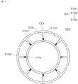
- FIG. 2 is a front view of the clamping member according to the first embodiment of the present invention
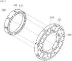
- FIG. 3 is a perspective view illustrating a modification of the clamping member according to the first embodiment of the present invention.
- the gas turbine includes a compressor rotor 100, a turbine rotor 200, a connection part 300, a tie rod 400, and a clamping member 500.
- the compressor rotor 100 includes a plurality of compressor rotor disks 102
- the turbine rotor 200 includes a plurality of turbine rotor disks 202
- the connection part 300 is installed to connect the compressor rotor 100 and the turbine rotor 200 to each other
- the tie rod 400 is extended through the center axes of the plurality of compressor rotor disks 102 and the center axes of the plurality of turbine rotor disks 202
- the clamping member 500 is forced onto the tie rod 400 in the axial direction of the tie rod 400 so as to be rotated with the tie rod 400, and relatively rotated with respect to the inner circumferential surface of the connection part 300.
- the clamping member 500 allows cooling air to move from the compressor rotor 100 to the turbine rotor 200 through the axial inside of the clamping member 500 and the circumferential edge of the clamping member 500 at the same time. Thus, a large amount of cooling air can be stably moved through the clamping member 500.
- the clamping member 500 includes an inner ring 510, a plurality of support parts 520, and a plurality of stiffeners 530.
- the inner ring 510 is pressed against the outer circumferential surface of the tie rod 400, the plurality of support parts 520 are arranged at predetermined intervals on the inner ring 510 such that one ends thereof are connected to the outer circumferential surface of the inner ring 510 and the other ends thereof are extended to the outside along the circumferential direction of the inner ring 510, and the plurality of stiffeners 530 are connected to the other ends of the respective support parts 520, and arranged along the circumferential direction while forming a concentric circle around the center of the inner ring 510.
- the inner ring 510 may be coupled to the tie rod 400 through a shrink fit method, and have an inner diameter corresponding to the outer diameter of the tie rod 400 such that the inner circumferential surface thereof is in contact with the outer circumferential surface of the tie rod 400. As illustrated in FIG. 2 , the inner ring 510 is formed in a ring shape with a predetermined diameter.
- the plurality of support parts 520 may be radially arranged on the outer circumferential surface of the inner ring 510 along the circumferential direction, and obliquely extended from the respective stiffeners 530 toward the inner ring 510 when the clamping member 500 is seen from the front.
- the support parts 520 may connect the inner ring 510 to the respective stiffeners 530 in various manners.
- the support parts 520 may be obliquely extended from the respective stiffeners 530 toward one side in order to improve a damping force in the center direction of the inner ring 510.
- the locations of the stiffeners 530 connected to the support parts 520 may be shifted in the circumferential direction through the rotation of the tie rod 400.
- the damping force may be changed depending on the inclination angle of the support part 520.
- an external force applied from the stiffener 530 toward the support part 520 is represented by F
- the external force F is divided into forces F1 and F2 by the inclination angle of the support part 520, and then transferred to the inner ring 510.
- the force F1 which is an external force applied in the same direction as the external force F is transferred to the inner ring 510 through the support part 520. Then, a part of the force F1 is transferred toward the axial center, and the other part of the force F1 is damped while being spread in the circumferential direction of the inner ring 510 as indicated by arrows.
- the force F2 is obliquely applied to the left through the stiffener 530 as illustrated in FIG. 2 .
- the force F2 may be applied in the 9 or 10 o'clock direction based on the clockwise direction.
- the support part 520 may damp the external force while being bent at a predetermined angle in the circumferential direction, and reduce a shock applied to the clamping member 500.
- the above-described embodiment is based on the case in which the external force F is applied to the stiffener 530 positioned in the 12 o'clock direction of the clamping member 500.
- the clamping member 500 can reduce a shock even though an external force is applied to a plurality of stiffeners 530 or an external force is applied to a stiffener located at an unspecified position.
- Each of the stiffeners 530 maintains a clearance C from another neighboring stiffener 530 in the circumferential direction. Since the clearance C provides a space through which cooling air can be moved, the clamping member 500 can perform a damping function and a cooling function at the same time.
- stiffeners 530 are connected to the respective support parts 520 connected to the inner ring 510, another neighboring stiffener is located in the one or 11 o'clock direction based on the stiffener 530 located in the 12 o'clock direction.
- the stiffener 530 located in the 12 o'clock direction is separated from another neighboring stiffener located in the circumferential direction, the plurality of stiffeners can independently perform damping in the circumferential direction.
- the clearance between the stiffener 530 and the neighboring stiffener is equally maintained among the plurality of stiffeners arranged in the circumferential direction.
- the stiffener 530 since the plurality of stiffeners are separated at even intervals from each other regardless of the locations thereof, the stiffener 530 may be moved by a distance corresponding to the clearance even when the stiffener 530 is moved toward the neighboring stiffener located at the left or right side thereof in the circumferential direction.
- the stiffener 530 can perform damping more stably through the movement in the circumferential direction.
- the clearance may be changed to a different clearance.
- cooling air can be moved from the compressor rotor 100 to the turbine rotor 200 through the clearance C between the stiffeners.
- the cooling performance can be improved.
- the clearance is set to a constant width from the compressor rotor 100 toward the turbine rotor 200 when the clamping member 500 is seen from the top.
- the clearance C may have a width that decreases toward the turbine rotor 200 from the compressor rotor 100.
- the moving speed of the cooling air is increased from the compressor rotor 100 toward the turbine rotor 200.
- a large amount of cooling air can be stably supplied while the moving speed and flow rate of the cooling air are increased.
- the stiffener 530 has a slope corresponding to the slope of the inner circumferential surface of the connection part 300 (refer to FIG. 1 ) when seen from the front.
- the stiffener 530 is rounded with a curvature corresponding to the curvature of the inner circumferential surface of the ring-shaped connection part 300, friction and unnecessary noise can be minimized even when the connection part 300 is coupled to the tie rod 400 and then rotated with the tie rod 400.
- FIG. 1 illustrates a cross-section of the connection part 300.
- the connection part 300 has a diameter and curvature corresponding to the outer circumferential surface of the stiffener 530.
- the stiffeners 530 are arranged so as to be top-bottom and left-right symmetrical with respect to the center of the inner ring 510.
- the stiffeners 530 are also top-bottom and left-right symmetrical with each other.
- the external force when an external force is transferred through the stiffeners 530 and the support parts 520, the external force may not be concentrated in a specific direction, but evenly supported and distributed, which makes it possible to improve the stability.
- the support part 520 is connected to the center of the bottom surface of the stiffener 530.
- the location where the support part 520 is connected is set based on the supposition that an external force is applied to the center of the outer circumferential surface of the stiffener 530.
- the support part 520 has an I-shaped cross-section, but may have a different cross-section such as a Y-shaped or T-shaped cross-section.
- the support part 520 is not limited to the shape illustrated in FIG. 3 .
- the inner ring 510 has a plurality of grooves 512 formed in the circumferential direction thereof, such that the support parts 520 are inserted into the respective grooves 512.
- the grooves 512 are formed in the outer circumferential surface in order to maintain a stable coupling of the support parts 520.
- the groove 512 may be formed in different shapes other than the shape illustrated in FIG. 5 , and the shape of the groove 512 or the support part 520 may be changed in such a manner that the support part 520 is more stably coupled to the groove 512.
- the support part 520 may be formed in a T-shape such that a temporarily fixed state thereof is maintained until the support part 520 is welded after being inserted into the groove 512.
- the support part 520 has an insertion piece 522 formed at the bottom thereof.
- the groove 512 has a shape corresponding to the cross-section of the low portion of the support part 520, the support part 520 can be stably inserted into the groove 512.
- the direction in which the support part 520 is inserted into the groove 512 may not be limited to the direction illustrated in FIG. 5 , but changed to a different direction. Since the insertion piece 522 of the support part 520 is inserted into the groove 512 while pressing against the groove 512, the support part 520 can be coupled to the groove 512 so as not to be separated from the groove 512.
- the support part 520 can be stably fixed through welding.
- the surface of the stiffener 530 which is relatively rotated with respect to the connection part 300, may be processed to have a low surface roughness.
- friction may occur between the stiffener 530 and the inner circumferential surface of the connection part 300.
- the friction may occur on the outer circumferential surface of the stiffener 530.
- the outer circumferential surface is processed to have a low surface roughness, the friction can be reduced. Thus, noise can be minimized.
- the damping ability of the clamping member 500 can be improved, while friction generated during rotation is minimized.
- the clamping member 500 includes the plurality of support parts 520 extended from the outer circumference of the inner ring 510 toward the respective stiffeners 530 in the normal direction P.
- the normal direction may indicate the direction in which the support part 520 is perpendicular to virtual lines a and a' drawn in a tangential direction on the circumference of the inner ring 510.
- the direction corresponds to an outward direction in which the stiffener 530 is located.
- the plurality of support parts 520 are arranged at predetermined intervals in the circumferential direction of the inner ring 510 while facing the outside in the normal direction.
- the support part 520 is extended from the outer circumferential surface of the inner ring 510 toward the stiffener 530 in the normal direction. Thus, even when an external force is applied in any directions, the support part 520 can stably damp the external force. Therefore, the damping force of the clamping member 500 can be improved.
- the external force transferred to the tie rod 400 can be reduced, and unnecessary vibration and noise can be minimized.
- the gas turbine according to the second embodiment of the present invention includes a compressor rotor 100a, a turbine rotor 200a, a connection part 300a, a tie rod 400a, and a clamping member 500a.
- the compressor rotor 100a includes a plurality of compressor rotor disks 102a
- the turbine rotor 200a includes a plurality of turbine rotor disks 202a
- the connection part 300a connects the compressor rotor 100a and the turbine rotor 200a to each other
- the tie rod 400a is extended through the center axes of the plurality of compressor rotor disks 102a and the center axes of the plurality of turbine rotor disks 202a
- the clamping member 500a is forced onto the tie rod 400a in the axial direction of the tie rod 400a so as to be rotated with the tie rod 400a, and relatively rotated with respect to the inner circumferential surface of the connection part 300a.
- the clamping member 500a allows cooling air to move from the compressor rotor 100a to the turbine rotor 200a through the axial inside of the clamping member 500a and the circumferential edge of the clamping member 500a at the same time.
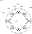
- the clamping member 500a includes an inner ring 510a, a plurality of extensions 520a and a plurality of stiffeners 530a.
- the inner ring 510a is pressed against the outer circumferential surface of the tie rod 400a, the plurality of extensions 520a are arranged at predetermined intervals such that one ends thereof are connected to the outer circumferential surface of the inner ring 510a and the other ends thereof are extended to the outside in the circumferential direction of the inner ring 510a, and the plurality of stiffeners 530 are connected to the other ends of the extensions 520a and arranged along the circumferential direction while forming a concentric circle around the center of the inner ring 510a.
- the inner ring 510a may be coupled to the tie rod 400a through a shrink fit method, for example, and have an inner diameter corresponding to the outer diameter of the tie rod 400a. As illustrated in FIG. 8 , the inner ring 510a may have a predetermined diameter.
- the plurality of extensions 520a may be obliquely extended toward the respective stiffeners 530a from the inner ring 510a along the circumferential direction of the inner ring 510a, when the clamping member 500a is seen from the front.
- the extensions 520a connect the inner ring 510a and the respective stiffeners 530a in various manners.
- the extensions 520a are obliquely extended in order to improve a damping force toward the center of the inner ring 510a from the stiffeners 530a, according to the rotation of the tie rod 400a.
- the positions of the stiffeners 530a connected to the extensions 520a may be shifted in the circumferential direction according to the rotation of the tie rod 400a.
- the clamping member 500a includes a damping part 600a for damping a force applied from the outside.
- the damping part 600a has one end fixed to the lower end of the extension 520a and the other end fixed to the outer circumferential surface of the inner ring 510a.
- the damping part 600a includes a plurality of unit damping part 600a1 to 600an which correspond to the respective stiffeners and are formed at predetermined intervals along the outer circumferential surface of the inner ring 510a.
- the reference numerals of the unit damping parts 610a1 to 610an may be sequentially set in the clockwise direction from the unit damping part 610a1 located at the 11 o'clock position.
- any one of a spring and plate spring which can damp a force applied from the outside may be selectively used as the damping part 600a. Furthermore, the damping part 600a can be changed to another component capable of generating an elastic restoring force.
- the damping part 600a includes a first damping part 610a having one end fixed to the lower end of the extension 520a and the other end fixed to the outer circumferential surface of the inner ring 510a.
- the first damping part 610a may be inserted and coupled to the outer circumferential surface of the inner ring 510a. In this case, the lower end of the first damping part 610a is partially inserted into the inner ring 510a and then fixed through welding.
- the first damping part 610a When the first damping part 610a is implemented with a coil spring or plate spring, the first damping part 610a can damp an external force applied in the radial direction of the inner ring 510a from the stiffener 530a and an external force applied in the circumferential direction of the inner ring 510a at the same time. Therefore, the damping performance can be improved in various directions in which external forces are applied.
- the damping part 600a further includes second damping parts 620a.
- One ends of the second damping parts 620a are connected to the left and right side surfaces of the extension 520a, respectively, and the other ends thereof are fixed to the outer circumferential surface of the inner ring 510a.
- the second damping parts 620a are connected to the left and right side surface surfaces of the extension 520a with the first damping part 610a.
- the second damping parts 620a may be configured to have the same spring constant at the left and right surfaces of the extension 520a based on FIG. 10 .
- any one of a spring and plate spring which can damp a force applied from outside may be selectively used as the damping part 600a. Furthermore, the damping part 600a can be changed to another component capable of generating an elastic restoring force.
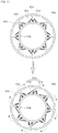
- the second damping part 620a positioned at the left side of the extension 520a based on FIG. 11 when the second damping part 620a positioned at the left side of the extension 520a based on FIG. 11 is compressed by an external force, the second damping part 620a positioned at the right side of the extension 520a is extended to damp an external force as indicated by an arrow.
- the second damping part 620a positioned at the right side of the extension 520a when the second damping part 620a positioned at the right side of the extension 520a is compressed, the second damping part 620a positioned at the left side of the extension 520a may be extended to stably damp an external force generated in the circumferential direction.
- the first and second damping parts 610a and 620a may be configured to retain different elastic restoring forces.
- the elastic restoring force of the first or second damping part 610a or 620a located at a position where damping is specifically required depending on the rotation of the tie rod 400 may be differently set.
- the damping part 600a may be extended in a zigzag manner toward the extension 520a from the inner ring 510a, and retain a width and thickness corresponding to the width of the inner ring 510a.
- the damping part 600a When the damping part 600a has a width and thickness corresponding to the width of the inner ring 510a, the damping part 600a can damp most of an external force applied to the stiffener 530a even though the damping performance differs depending on the magnitude of the external force.
- the damping part may include a metal or high-elasticity metal capable of retaining an elastic restoring force, and not be limited to a specific material.
- the gas turbine can damp vibration generated therein, minimize a damage of the components, which may be caused by the vibration and shock, and perform cooling to minimize a problem caused by overheating.
- the gas turbine can damp shock and vibration transferred in the radial or axial direction through rotation of the tie rod.
Landscapes
- Engineering & Computer Science (AREA)
- Mechanical Engineering (AREA)
- General Engineering & Computer Science (AREA)
- Chemical & Material Sciences (AREA)
- Combustion & Propulsion (AREA)
- Structures Of Non-Positive Displacement Pumps (AREA)
- Turbine Rotor Nozzle Sealing (AREA)
Applications Claiming Priority (1)
| Application Number | Priority Date | Filing Date | Title |
|---|---|---|---|
| KR1020160153360A KR101871060B1 (ko) | 2016-11-17 | 2016-11-17 | 가스터빈 |
Publications (2)
| Publication Number | Publication Date |
|---|---|
| EP3323980A1 true EP3323980A1 (de) | 2018-05-23 |
| EP3323980B1 EP3323980B1 (de) | 2019-03-13 |
Family
ID=60327220
Family Applications (1)
| Application Number | Title | Priority Date | Filing Date |
|---|---|---|---|
| EP17201894.7A Active EP3323980B1 (de) | 2016-11-17 | 2017-11-15 | Gasturbine |
Country Status (4)
| Country | Link |
|---|---|
| US (1) | US10731468B2 (de) |
| EP (1) | EP3323980B1 (de) |
| JP (1) | JP6478172B2 (de) |
| KR (1) | KR101871060B1 (de) |
Families Citing this family (1)
| Publication number | Priority date | Publication date | Assignee | Title |
|---|---|---|---|---|
| IT202100010781A1 (it) * | 2021-04-28 | 2022-10-28 | Nuovo Pignone Tecnologie Srl | Rotore di turbomacchina con giranti impilate e turbomacchina |
Citations (4)
| Publication number | Priority date | Publication date | Assignee | Title |
|---|---|---|---|---|
| EP1970528A1 (de) * | 2007-03-12 | 2008-09-17 | Siemens Aktiengesellschaft | Läufer einer thermischen Strömungsmaschine |
| US20090282679A1 (en) * | 2008-01-23 | 2009-11-19 | Snecma | Centering a part inside a shaft |
| US8506239B2 (en) | 2007-03-12 | 2013-08-13 | Siemens Aktiengesellschaft | Turbine with at least one rotor which comprises rotor disks and a tie-bolt |
| US20150198044A1 (en) * | 2014-01-15 | 2015-07-16 | Doosan Heavy Industries & Construction Co., Ltd. | Gas turbine having damping clamp |
Family Cites Families (3)
| Publication number | Priority date | Publication date | Assignee | Title |
|---|---|---|---|---|
| JP4928857B2 (ja) * | 2006-07-12 | 2012-05-09 | 三菱重工業株式会社 | 軸受支持構造及びガスタービン |
| JP6455179B2 (ja) * | 2015-01-26 | 2019-01-23 | 株式会社Ihi | センターベントチューブ調芯機構及びセンターベントチューブ支持装置 |
| KR101675269B1 (ko) * | 2015-10-02 | 2016-11-11 | 두산중공업 주식회사 | 가스터빈 디스크 |
-
2016
- 2016-11-17 KR KR1020160153360A patent/KR101871060B1/ko active Active
-
2017
- 2017-11-13 JP JP2017218533A patent/JP6478172B2/ja active Active
- 2017-11-15 US US15/814,120 patent/US10731468B2/en active Active
- 2017-11-15 EP EP17201894.7A patent/EP3323980B1/de active Active
Patent Citations (4)
| Publication number | Priority date | Publication date | Assignee | Title |
|---|---|---|---|---|
| EP1970528A1 (de) * | 2007-03-12 | 2008-09-17 | Siemens Aktiengesellschaft | Läufer einer thermischen Strömungsmaschine |
| US8506239B2 (en) | 2007-03-12 | 2013-08-13 | Siemens Aktiengesellschaft | Turbine with at least one rotor which comprises rotor disks and a tie-bolt |
| US20090282679A1 (en) * | 2008-01-23 | 2009-11-19 | Snecma | Centering a part inside a shaft |
| US20150198044A1 (en) * | 2014-01-15 | 2015-07-16 | Doosan Heavy Industries & Construction Co., Ltd. | Gas turbine having damping clamp |
Also Published As
| Publication number | Publication date |
|---|---|
| EP3323980B1 (de) | 2019-03-13 |
| KR101871060B1 (ko) | 2018-06-25 |
| KR20180055475A (ko) | 2018-05-25 |
| JP2018080700A (ja) | 2018-05-24 |
| JP6478172B2 (ja) | 2019-03-06 |
| US10731468B2 (en) | 2020-08-04 |
| US20180135416A1 (en) | 2018-05-17 |
Similar Documents
| Publication | Publication Date | Title |
|---|---|---|
| JP5551758B2 (ja) | ステータアッセンブリ、その製造方法およびダンパスプリング | |
| EP3112588B1 (de) | Rotordämpfer | |
| US8104290B2 (en) | Combustion liner damper | |
| US7534090B2 (en) | Enhanced bucket vibration system | |
| CA2714740C (en) | Radial balancing clip weight for rotor assembly | |
| JP5604512B2 (ja) | 係着式ばね釣合いおもり及びロータアセンブリ | |
| JP6730031B2 (ja) | タービン動翼を取り付けるための固定治具および方法 | |
| US20120207603A1 (en) | Trapped spring balance weight and rotor assembly | |
| CN105765168B (zh) | 径向系紧螺栓支承弹簧 | |
| US10472975B2 (en) | Damper pin having elongated bodies for damping adjacent turbine blades | |
| JP7638679B2 (ja) | ターボ機械ロータブレード用のダンパスタック | |
| CN102301095B (zh) | 涡轮机叶片系统 | |
| CN108223024A (zh) | 涡轮叶片至转子轮的转移 | |
| US11634991B1 (en) | Vibration damping system for turbine nozzle or blade using elongated body and wire mesh member | |
| US11519276B1 (en) | Vibration damping system for turbine blade or nozzle, retention system therefor, and method of assembly | |
| EP3323980B1 (de) | Gasturbine | |
| JP2021156286A (ja) | 改善されたロータブレードの制振構造 | |
| US10267168B2 (en) | Vane ring for a turbine engine having retention devices | |
| JP2015530518A (ja) | Cmcタービンブレード用の自己固定型ファスナ | |
| JP6027224B2 (ja) | トラップ式バランスウェイトおよびロータ組立体 | |
| JP2016507020A (ja) | ターボ機械の動翼係止組立体および固定方法 | |
| US11248797B2 (en) | Axial stop configuration for a combustion liner |
Legal Events
| Date | Code | Title | Description |
|---|---|---|---|
| PUAI | Public reference made under article 153(3) epc to a published international application that has entered the european phase |
Free format text: ORIGINAL CODE: 0009012 |
|
| STAA | Information on the status of an ep patent application or granted ep patent |
Free format text: STATUS: REQUEST FOR EXAMINATION WAS MADE |
|
| 17P | Request for examination filed |
Effective date: 20171115 |
|
| AK | Designated contracting states |
Kind code of ref document: A1 Designated state(s): AL AT BE BG CH CY CZ DE DK EE ES FI FR GB GR HR HU IE IS IT LI LT LU LV MC MK MT NL NO PL PT RO RS SE SI SK SM TR |
|
| AX | Request for extension of the european patent |
Extension state: BA ME |
|
| RBV | Designated contracting states (corrected) |
Designated state(s): AL AT BE BG CH CY CZ DE DK EE ES FI FR GB GR HR HU IE IS IT LI LT LU LV MC MK MT NL NO PL PT RO RS SE SI SK SM TR |
|
| GRAJ | Information related to disapproval of communication of intention to grant by the applicant or resumption of examination proceedings by the epo deleted |
Free format text: ORIGINAL CODE: EPIDOSDIGR1 |
|
| STAA | Information on the status of an ep patent application or granted ep patent |
Free format text: STATUS: GRANT OF PATENT IS INTENDED |
|
| GRAP | Despatch of communication of intention to grant a patent |
Free format text: ORIGINAL CODE: EPIDOSNIGR1 |
|
| INTG | Intention to grant announced |
Effective date: 20180809 |
|
| GRAS | Grant fee paid |
Free format text: ORIGINAL CODE: EPIDOSNIGR3 |
|
| GRAA | (expected) grant |
Free format text: ORIGINAL CODE: 0009210 |
|
| STAA | Information on the status of an ep patent application or granted ep patent |
Free format text: STATUS: THE PATENT HAS BEEN GRANTED |
|
| AK | Designated contracting states |
Kind code of ref document: B1 Designated state(s): AL AT BE BG CH CY CZ DE DK EE ES FI FR GB GR HR HU IE IS IT LI LT LU LV MC MK MT NL NO PL PT RO RS SE SI SK SM TR |
|
| REG | Reference to a national code |
Ref country code: GB Ref legal event code: FG4D |
|
| REG | Reference to a national code |
Ref country code: CH Ref legal event code: EP Ref country code: AT Ref legal event code: REF Ref document number: 1107932 Country of ref document: AT Kind code of ref document: T Effective date: 20190315 |
|
| REG | Reference to a national code |
Ref country code: IE Ref legal event code: FG4D |
|
| REG | Reference to a national code |
Ref country code: DE Ref legal event code: R096 Ref document number: 602017002713 Country of ref document: DE |
|
| REG | Reference to a national code |
Ref country code: NL Ref legal event code: MP Effective date: 20190313 |
|
| REG | Reference to a national code |
Ref country code: LT Ref legal event code: MG4D |
|
| PG25 | Lapsed in a contracting state [announced via postgrant information from national office to epo] |
Ref country code: FI Free format text: LAPSE BECAUSE OF FAILURE TO SUBMIT A TRANSLATION OF THE DESCRIPTION OR TO PAY THE FEE WITHIN THE PRESCRIBED TIME-LIMIT Effective date: 20190313 Ref country code: LT Free format text: LAPSE BECAUSE OF FAILURE TO SUBMIT A TRANSLATION OF THE DESCRIPTION OR TO PAY THE FEE WITHIN THE PRESCRIBED TIME-LIMIT Effective date: 20190313 Ref country code: NO Free format text: LAPSE BECAUSE OF FAILURE TO SUBMIT A TRANSLATION OF THE DESCRIPTION OR TO PAY THE FEE WITHIN THE PRESCRIBED TIME-LIMIT Effective date: 20190613 Ref country code: SE Free format text: LAPSE BECAUSE OF FAILURE TO SUBMIT A TRANSLATION OF THE DESCRIPTION OR TO PAY THE FEE WITHIN THE PRESCRIBED TIME-LIMIT Effective date: 20190313 |
|
| PG25 | Lapsed in a contracting state [announced via postgrant information from national office to epo] |
Ref country code: GR Free format text: LAPSE BECAUSE OF FAILURE TO SUBMIT A TRANSLATION OF THE DESCRIPTION OR TO PAY THE FEE WITHIN THE PRESCRIBED TIME-LIMIT Effective date: 20190614 Ref country code: RS Free format text: LAPSE BECAUSE OF FAILURE TO SUBMIT A TRANSLATION OF THE DESCRIPTION OR TO PAY THE FEE WITHIN THE PRESCRIBED TIME-LIMIT Effective date: 20190313 Ref country code: HR Free format text: LAPSE BECAUSE OF FAILURE TO SUBMIT A TRANSLATION OF THE DESCRIPTION OR TO PAY THE FEE WITHIN THE PRESCRIBED TIME-LIMIT Effective date: 20190313 Ref country code: LV Free format text: LAPSE BECAUSE OF FAILURE TO SUBMIT A TRANSLATION OF THE DESCRIPTION OR TO PAY THE FEE WITHIN THE PRESCRIBED TIME-LIMIT Effective date: 20190313 Ref country code: BG Free format text: LAPSE BECAUSE OF FAILURE TO SUBMIT A TRANSLATION OF THE DESCRIPTION OR TO PAY THE FEE WITHIN THE PRESCRIBED TIME-LIMIT Effective date: 20190613 Ref country code: NL Free format text: LAPSE BECAUSE OF FAILURE TO SUBMIT A TRANSLATION OF THE DESCRIPTION OR TO PAY THE FEE WITHIN THE PRESCRIBED TIME-LIMIT Effective date: 20190313 |
|
| REG | Reference to a national code |
Ref country code: AT Ref legal event code: MK05 Ref document number: 1107932 Country of ref document: AT Kind code of ref document: T Effective date: 20190313 |
|
| PG25 | Lapsed in a contracting state [announced via postgrant information from national office to epo] |
Ref country code: ES Free format text: LAPSE BECAUSE OF FAILURE TO SUBMIT A TRANSLATION OF THE DESCRIPTION OR TO PAY THE FEE WITHIN THE PRESCRIBED TIME-LIMIT Effective date: 20190313 Ref country code: AL Free format text: LAPSE BECAUSE OF FAILURE TO SUBMIT A TRANSLATION OF THE DESCRIPTION OR TO PAY THE FEE WITHIN THE PRESCRIBED TIME-LIMIT Effective date: 20190313 Ref country code: PT Free format text: LAPSE BECAUSE OF FAILURE TO SUBMIT A TRANSLATION OF THE DESCRIPTION OR TO PAY THE FEE WITHIN THE PRESCRIBED TIME-LIMIT Effective date: 20190713 Ref country code: EE Free format text: LAPSE BECAUSE OF FAILURE TO SUBMIT A TRANSLATION OF THE DESCRIPTION OR TO PAY THE FEE WITHIN THE PRESCRIBED TIME-LIMIT Effective date: 20190313 Ref country code: IT Free format text: LAPSE BECAUSE OF FAILURE TO SUBMIT A TRANSLATION OF THE DESCRIPTION OR TO PAY THE FEE WITHIN THE PRESCRIBED TIME-LIMIT Effective date: 20190313 Ref country code: SK Free format text: LAPSE BECAUSE OF FAILURE TO SUBMIT A TRANSLATION OF THE DESCRIPTION OR TO PAY THE FEE WITHIN THE PRESCRIBED TIME-LIMIT Effective date: 20190313 Ref country code: CZ Free format text: LAPSE BECAUSE OF FAILURE TO SUBMIT A TRANSLATION OF THE DESCRIPTION OR TO PAY THE FEE WITHIN THE PRESCRIBED TIME-LIMIT Effective date: 20190313 Ref country code: RO Free format text: LAPSE BECAUSE OF FAILURE TO SUBMIT A TRANSLATION OF THE DESCRIPTION OR TO PAY THE FEE WITHIN THE PRESCRIBED TIME-LIMIT Effective date: 20190313 |
|
| PG25 | Lapsed in a contracting state [announced via postgrant information from national office to epo] |
Ref country code: SM Free format text: LAPSE BECAUSE OF FAILURE TO SUBMIT A TRANSLATION OF THE DESCRIPTION OR TO PAY THE FEE WITHIN THE PRESCRIBED TIME-LIMIT Effective date: 20190313 Ref country code: PL Free format text: LAPSE BECAUSE OF FAILURE TO SUBMIT A TRANSLATION OF THE DESCRIPTION OR TO PAY THE FEE WITHIN THE PRESCRIBED TIME-LIMIT Effective date: 20190313 |
|
| REG | Reference to a national code |
Ref country code: DE Ref legal event code: R097 Ref document number: 602017002713 Country of ref document: DE |
|
| PG25 | Lapsed in a contracting state [announced via postgrant information from national office to epo] |
Ref country code: IS Free format text: LAPSE BECAUSE OF FAILURE TO SUBMIT A TRANSLATION OF THE DESCRIPTION OR TO PAY THE FEE WITHIN THE PRESCRIBED TIME-LIMIT Effective date: 20190713 Ref country code: AT Free format text: LAPSE BECAUSE OF FAILURE TO SUBMIT A TRANSLATION OF THE DESCRIPTION OR TO PAY THE FEE WITHIN THE PRESCRIBED TIME-LIMIT Effective date: 20190313 |
|
| PLBE | No opposition filed within time limit |
Free format text: ORIGINAL CODE: 0009261 |
|
| STAA | Information on the status of an ep patent application or granted ep patent |
Free format text: STATUS: NO OPPOSITION FILED WITHIN TIME LIMIT |
|
| PG25 | Lapsed in a contracting state [announced via postgrant information from national office to epo] |
Ref country code: DK Free format text: LAPSE BECAUSE OF FAILURE TO SUBMIT A TRANSLATION OF THE DESCRIPTION OR TO PAY THE FEE WITHIN THE PRESCRIBED TIME-LIMIT Effective date: 20190313 |
|
| 26N | No opposition filed |
Effective date: 20191216 |
|
| PG25 | Lapsed in a contracting state [announced via postgrant information from national office to epo] |
Ref country code: TR Free format text: LAPSE BECAUSE OF FAILURE TO SUBMIT A TRANSLATION OF THE DESCRIPTION OR TO PAY THE FEE WITHIN THE PRESCRIBED TIME-LIMIT Effective date: 20190313 |
|
| PG25 | Lapsed in a contracting state [announced via postgrant information from national office to epo] |
Ref country code: MC Free format text: LAPSE BECAUSE OF FAILURE TO SUBMIT A TRANSLATION OF THE DESCRIPTION OR TO PAY THE FEE WITHIN THE PRESCRIBED TIME-LIMIT Effective date: 20190313 Ref country code: LU Free format text: LAPSE BECAUSE OF NON-PAYMENT OF DUE FEES Effective date: 20191115 |
|
| REG | Reference to a national code |
Ref country code: BE Ref legal event code: MM Effective date: 20191130 |
|
| PG25 | Lapsed in a contracting state [announced via postgrant information from national office to epo] |
Ref country code: IE Free format text: LAPSE BECAUSE OF NON-PAYMENT OF DUE FEES Effective date: 20191115 |
|
| PG25 | Lapsed in a contracting state [announced via postgrant information from national office to epo] |
Ref country code: BE Free format text: LAPSE BECAUSE OF NON-PAYMENT OF DUE FEES Effective date: 20191130 |
|
| PG25 | Lapsed in a contracting state [announced via postgrant information from national office to epo] |
Ref country code: CY Free format text: LAPSE BECAUSE OF FAILURE TO SUBMIT A TRANSLATION OF THE DESCRIPTION OR TO PAY THE FEE WITHIN THE PRESCRIBED TIME-LIMIT Effective date: 20190313 |
|
| REG | Reference to a national code |
Ref country code: CH Ref legal event code: PL |
|
| PG25 | Lapsed in a contracting state [announced via postgrant information from national office to epo] |
Ref country code: HU Free format text: LAPSE BECAUSE OF FAILURE TO SUBMIT A TRANSLATION OF THE DESCRIPTION OR TO PAY THE FEE WITHIN THE PRESCRIBED TIME-LIMIT; INVALID AB INITIO Effective date: 20171115 Ref country code: MT Free format text: LAPSE BECAUSE OF FAILURE TO SUBMIT A TRANSLATION OF THE DESCRIPTION OR TO PAY THE FEE WITHIN THE PRESCRIBED TIME-LIMIT Effective date: 20190313 |
|
| PG25 | Lapsed in a contracting state [announced via postgrant information from national office to epo] |
Ref country code: CH Free format text: LAPSE BECAUSE OF NON-PAYMENT OF DUE FEES Effective date: 20201130 Ref country code: LI Free format text: LAPSE BECAUSE OF NON-PAYMENT OF DUE FEES Effective date: 20201130 |
|
| PG25 | Lapsed in a contracting state [announced via postgrant information from national office to epo] |
Ref country code: SI Free format text: LAPSE BECAUSE OF FAILURE TO SUBMIT A TRANSLATION OF THE DESCRIPTION OR TO PAY THE FEE WITHIN THE PRESCRIBED TIME-LIMIT Effective date: 20190313 |
|
| PG25 | Lapsed in a contracting state [announced via postgrant information from national office to epo] |
Ref country code: MK Free format text: LAPSE BECAUSE OF FAILURE TO SUBMIT A TRANSLATION OF THE DESCRIPTION OR TO PAY THE FEE WITHIN THE PRESCRIBED TIME-LIMIT Effective date: 20190313 |
|
| GBPC | Gb: european patent ceased through non-payment of renewal fee |
Effective date: 20211115 |
|
| PG25 | Lapsed in a contracting state [announced via postgrant information from national office to epo] |
Ref country code: GB Free format text: LAPSE BECAUSE OF NON-PAYMENT OF DUE FEES Effective date: 20211115 |
|
| PGFP | Annual fee paid to national office [announced via postgrant information from national office to epo] |
Ref country code: FR Payment date: 20250908 Year of fee payment: 9 |
|
| PGFP | Annual fee paid to national office [announced via postgrant information from national office to epo] |
Ref country code: DE Payment date: 20250923 Year of fee payment: 9 |