EP3324074A1 - Hydraulischer dämpfer mit dualem modus - Google Patents
Hydraulischer dämpfer mit dualem modus Download PDFInfo
- Publication number
- EP3324074A1 EP3324074A1 EP17200607.4A EP17200607A EP3324074A1 EP 3324074 A1 EP3324074 A1 EP 3324074A1 EP 17200607 A EP17200607 A EP 17200607A EP 3324074 A1 EP3324074 A1 EP 3324074A1
- Authority
- EP
- European Patent Office
- Prior art keywords
- rebound
- compression
- hydraulic damper
- chamber
- disposed
- Prior art date
- Legal status (The legal status is an assumption and is not a legal conclusion. Google has not performed a legal analysis and makes no representation as to the accuracy of the status listed.)
- Granted
Links
Images



Classifications
-
- F—MECHANICAL ENGINEERING; LIGHTING; HEATING; WEAPONS; BLASTING
- F16—ENGINEERING ELEMENTS AND UNITS; GENERAL MEASURES FOR PRODUCING AND MAINTAINING EFFECTIVE FUNCTIONING OF MACHINES OR INSTALLATIONS; THERMAL INSULATION IN GENERAL
- F16F—SPRINGS; SHOCK-ABSORBERS; MEANS FOR DAMPING VIBRATION
- F16F9/00—Springs, vibration-dampers, shock-absorbers, or similarly-constructed movement-dampers using a fluid or the equivalent as damping medium
- F16F9/10—Springs, vibration-dampers, shock-absorbers, or similarly-constructed movement-dampers using a fluid or the equivalent as damping medium using liquid only; using a fluid of which the nature is immaterial
- F16F9/14—Devices with one or more members, e.g. pistons, vanes, moving to and fro in chambers and using throttling effect
- F16F9/16—Devices with one or more members, e.g. pistons, vanes, moving to and fro in chambers and using throttling effect involving only straight-line movement of the effective parts
- F16F9/18—Devices with one or more members, e.g. pistons, vanes, moving to and fro in chambers and using throttling effect involving only straight-line movement of the effective parts with a closed cylinder and a piston separating two or more working spaces therein
- F16F9/19—Devices with one or more members, e.g. pistons, vanes, moving to and fro in chambers and using throttling effect involving only straight-line movement of the effective parts with a closed cylinder and a piston separating two or more working spaces therein with a single cylinder and of single-tube type
-
- F—MECHANICAL ENGINEERING; LIGHTING; HEATING; WEAPONS; BLASTING
- F16—ENGINEERING ELEMENTS AND UNITS; GENERAL MEASURES FOR PRODUCING AND MAINTAINING EFFECTIVE FUNCTIONING OF MACHINES OR INSTALLATIONS; THERMAL INSULATION IN GENERAL
- F16F—SPRINGS; SHOCK-ABSORBERS; MEANS FOR DAMPING VIBRATION
- F16F9/00—Springs, vibration-dampers, shock-absorbers, or similarly-constructed movement-dampers using a fluid or the equivalent as damping medium
- F16F9/32—Details
- F16F9/44—Means on or in the damper for manual or non-automatic adjustment; such means combined with temperature correction
- F16F9/46—Means on or in the damper for manual or non-automatic adjustment; such means combined with temperature correction allowing control from a distance, i.e. location of means for control input being remote from site of valves, e.g. on damper external wall
- F16F9/466—Throttling control, i.e. regulation of flow passage geometry
-
- B—PERFORMING OPERATIONS; TRANSPORTING
- B60—VEHICLES IN GENERAL
- B60G—VEHICLE SUSPENSION ARRANGEMENTS
- B60G13/00—Resilient suspensions characterised by arrangement, location or type of vibration dampers
- B60G13/02—Resilient suspensions characterised by arrangement, location or type of vibration dampers having dampers dissipating energy, e.g. frictionally
- B60G13/06—Resilient suspensions characterised by arrangement, location or type of vibration dampers having dampers dissipating energy, e.g. frictionally of fluid type
- B60G13/08—Resilient suspensions characterised by arrangement, location or type of vibration dampers having dampers dissipating energy, e.g. frictionally of fluid type hydraulic
-
- F—MECHANICAL ENGINEERING; LIGHTING; HEATING; WEAPONS; BLASTING
- F16—ENGINEERING ELEMENTS AND UNITS; GENERAL MEASURES FOR PRODUCING AND MAINTAINING EFFECTIVE FUNCTIONING OF MACHINES OR INSTALLATIONS; THERMAL INSULATION IN GENERAL
- F16F—SPRINGS; SHOCK-ABSORBERS; MEANS FOR DAMPING VIBRATION
- F16F9/00—Springs, vibration-dampers, shock-absorbers, or similarly-constructed movement-dampers using a fluid or the equivalent as damping medium
- F16F9/32—Details
- F16F9/34—Special valve constructions; Shape or construction of throttling passages
- F16F9/348—Throttling passages in the form of annular discs or other plate-like elements which may or may not have a spring action, operating in opposite directions or singly, e.g. annular discs positioned on top of the valve or piston body
-
- F—MECHANICAL ENGINEERING; LIGHTING; HEATING; WEAPONS; BLASTING
- F16—ENGINEERING ELEMENTS AND UNITS; GENERAL MEASURES FOR PRODUCING AND MAINTAINING EFFECTIVE FUNCTIONING OF MACHINES OR INSTALLATIONS; THERMAL INSULATION IN GENERAL
- F16F—SPRINGS; SHOCK-ABSORBERS; MEANS FOR DAMPING VIBRATION
- F16F9/00—Springs, vibration-dampers, shock-absorbers, or similarly-constructed movement-dampers using a fluid or the equivalent as damping medium
- F16F9/32—Details
- F16F9/44—Means on or in the damper for manual or non-automatic adjustment; such means combined with temperature correction
- F16F9/446—Adjustment of valve bias or pre-stress
-
- F—MECHANICAL ENGINEERING; LIGHTING; HEATING; WEAPONS; BLASTING
- F16—ENGINEERING ELEMENTS AND UNITS; GENERAL MEASURES FOR PRODUCING AND MAINTAINING EFFECTIVE FUNCTIONING OF MACHINES OR INSTALLATIONS; THERMAL INSULATION IN GENERAL
- F16F—SPRINGS; SHOCK-ABSORBERS; MEANS FOR DAMPING VIBRATION
- F16F9/00—Springs, vibration-dampers, shock-absorbers, or similarly-constructed movement-dampers using a fluid or the equivalent as damping medium
- F16F9/32—Details
- F16F9/44—Means on or in the damper for manual or non-automatic adjustment; such means combined with temperature correction
- F16F9/46—Means on or in the damper for manual or non-automatic adjustment; such means combined with temperature correction allowing control from a distance, i.e. location of means for control input being remote from site of valves, e.g. on damper external wall
- F16F9/463—Means on or in the damper for manual or non-automatic adjustment; such means combined with temperature correction allowing control from a distance, i.e. location of means for control input being remote from site of valves, e.g. on damper external wall characterised by electrical connections
-
- B—PERFORMING OPERATIONS; TRANSPORTING
- B60—VEHICLES IN GENERAL
- B60G—VEHICLE SUSPENSION ARRANGEMENTS
- B60G2206/00—Indexing codes related to the manufacturing of suspensions: constructional features, the materials used, procedures or tools
- B60G2206/01—Constructional features of suspension elements, e.g. arms, dampers, springs
- B60G2206/012—Hollow or tubular elements
-
- F—MECHANICAL ENGINEERING; LIGHTING; HEATING; WEAPONS; BLASTING
- F16—ENGINEERING ELEMENTS AND UNITS; GENERAL MEASURES FOR PRODUCING AND MAINTAINING EFFECTIVE FUNCTIONING OF MACHINES OR INSTALLATIONS; THERMAL INSULATION IN GENERAL
- F16F—SPRINGS; SHOCK-ABSORBERS; MEANS FOR DAMPING VIBRATION
- F16F2230/00—Purpose; Design features
- F16F2230/18—Control arrangements
Definitions
- the invention relates to a hydraulic damper, in particular a motor vehicle suspension damper. More specifically, a hydraulic damper electrically switchable between two different stiffness settings.
- dampers which are operable in either of two different stiffness settings (soft & firm), also known as “comfort mode” and “sport mode”, respectively.
- Such "dual mode” dampers may be switchable manually by the user, such as by a button on the dashboard, or automatically, such as by a vehicle's ECU.
- U.S. Patent 7,156,214 discloses a hydraulic damper piston with two valve assemblies and an electric actuator which selectively allows fluid to flow through one of the valve assemblies, while at the same time causing internal pistons to move in order to adjust the effective volume of the compression and rebound chambers.
- U.S. Patent 6,668,987 discloses a hydraulic damper piston which includes a valve body with rebound and compression passages and with a plurality of compression discs and a plurality of rebound discs deflectably covering the compression passages and rebound passages respectively for restricting the flow of the working fluid therebetween during the a corresponding stroke and for blocking the flow of the working fluid therebetween during the opposite stroke of the damper.
- the invention provides for a hydraulic damper, in particular a motor vehicle suspension damper including a tube filled with working liquid inside of which a piston assembly is disposed, dividing the tube into a compression chamber and a rebound chamber.
- the piston assembly includes a housing defining an interior space, with an opening in the housing to allow the working liquid to flow between the rebound chamber and a first internal chamber in the interior space.
- the piston assembly includes an armature defining a first borehole extending therethrough and a sleeve defining a bypass passage in fluid communication with the first borehole.
- a first valve assembly separates the first internal chamber from a second internal chamber in fluid communication with the bypass passage.
- a second valve assembly separates the second internal chamber from the compression chamber of the tube.
- a spring engages and biases the armature to a first position, also known as a default position, with the rebound chamber in fluid communication with the bypass passage.
- the armature is moveable to a second position in response to an electrical current in a coil of conductive wire, in which fluid communication between the rebound chamber and the bypass passage is blocked.
- the armature In the first position, with the coil not energized, the armature causes the working fluid to bypass the first valve in both rebound and compression strokes of the damper.
- the working fluid is primarily restricted only by the second valve assembly.
- the hydraulic damper operates in a less stiff, or "comfort mode".
- the armature With the coil energized, the armature moves to the second position, in which the working fluid does not bypass the first valve, and instead is restricted by both the first and second valves in both rebound and compression strokes to provide a stiffer dampening effect.
- the damper may be placed in a stiffer, or "sport mode” by energizing the coil, and the damper will default to a less stiff, or "comfort mode” with the coil de-energized.
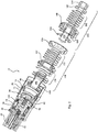
- a hydraulic damper 10 in particular a motor vehicle suspension damper 10 is generally shown and described in cross section in Fig. 1 and in exploded view in Fig. 2 .
- the hydraulic damper 10 includes a tube 20 which is substantially closed at both ends and filled with working liquid, inside of which a piston assembly 22 is disposed, dividing the tube 20 into a compression chamber 24 and a rebound chamber 26.
- the piston assembly 22 controls the flow of working liquid passing therethrough during rebound and compression strokes of the damper 10.
- the piston assembly 22 includes a housing 28 having a hollow cylindrical shape disposed about an axis A and defining an interior surface 30 and an exterior surface 32, each extending axially and circumferentially from a bottom 34 to define an interior space.
- a stem 36 having a cylindrical shape extends from the bottom 34 axially away from the housing 28 and fits within a hollow end 38 of a piston rod 40 and defines a first external thread 42 for engaging a first internal thread 44 in the hollow end 38 of the piston rod 40 to secure the piston assembly 22 thereupon.
- the stem 36 also defines a first annular channel thereabout holding a first O-ring providing a seal between the stem 36 and the hollow end 38 of the piston rod 40.
- a first retaining ring 46 may be disposed between the bottom 34 and a first shoulder 48 of the piston rod 40 for holding the piston assembly 22 thereupon by preventing the piston assembly 22 from unscrewing from the piston rod 40.
- An annular seal 50 is disposed circumferentially about the housing 28 of the piston assembly 22 for sealingly engaging the tube 20 and dividing the compression chamber 24 from the rebound chamber 26.
- An electrical cable 52 extends through the piston rod 40 and through the stem 36 and the bottom 34 of the piston assembly 22.
- a ferrule 54 surrounds and secures the electrical cable 52 in the piston assembly 22 at the point where the electrical cable 52 passes through the bottom 34 of the piston assembly 22, and may provide a fluid-tight seal around the electrical cable 52.
- the piston assembly 22 includes a spool 56 disposed in the interior space of the housing 28 adjacent the bottom 34 with a coil 58 of conductive wire in electrical communication with the electrical cable 52 wrapped about the spool 56 between a radial first wall 60 located adjacent to the bottom 34 and a radial second wall 62 axially spaced from the bottom 34.
- the radial second wall 62 defines a second annular channel which holds a second O-ring for sealingly engaging the interior surface 30 and isolating the coil 58 from the working liquid.
- An electromagnet core 64 is disposed within the spool 56 and inside of the coil 58.
- the electromagnet core 64 defines a first pocket 66 extending axially and partially therethrough with an opening opposite the bottom 34 of the housing 28.
- the interior and exterior surfaces 30, 32 of the housing 28 define a first step 68 extending circumferentially thereabout and adjacent the second wall 62 of the spool 56 and widening to a larger diameter away from the bottom 34 with a plurality of first transverse openings 70 therethrough and circumferentially thereabout to allow free flow of the working liquid between the rebound chamber 26 and a first internal chamber 72 in the interior space of the housing 28.
- the piston assembly 22 also includes a plunger guide 74 disposed in the interior space of the housing 28 engaging the interior surface 30 at the first step 68 and defining a guide chamber having a cylindrical shape coaxial with the housing 28 with an armature 76 disposed therein and moveable between a first position axially spaced from the electromagnet core 64 and a second position contacting the electromagnet core 64.
- the armature 76 defines a second pocket 78 having a cylindrical shape coaxial with the housing 28 extending partially therethrough and facing the first pocket 66 in the electromagnet core 64.
- the armature 76 also defines a plurality of first boreholes 80 extending therethrough and angled inwardly from a lower end 82 adjacent the electromagnet core 64 to a central chamber 84 in the armature 76 axially spaced from the electromagnet core 64.
- a protrusion 86 extends circumferentially and axially from the plunger guide 74 away from the bottom 34 and defines a third pocket 88 having a cylindrical shape coaxial with the housing 28.
- a plurality of connecting passages 90 extend axially through and circumferentially about the plunger guide 74 to allow free flow of the working liquid from the first transverse openings 70 to the first internal chamber 72 axially beyond the plunger guide 74, away from the bottom 34 of the housing 28.
- the piston assembly 22 also includes a plurality second transverse openings 92 extending through and circumferentially about the housing 28 proximate to the protrusion 86 in the plunger guide 74 to allow additional flow of the working liquid between the rebound chamber 26 and the first internal chamber 72.
- a second step in the exterior surface 32 of the housing 28 defines a widened portion 94 of the piston assembly 22 with the annular seal 50 disposed thereupon and with the transverse openings 70, 92 disposed between the bottom 34 and the widened portion 94.
- the piston assembly 22 also includes a sleeve 96 having a flange 98 disposed within the third pocket 88 of the plunger guide 74 and which extends to a rim 100, which defines a third annular channel holding a third O-Ring forming a seal between the flange 98 and the plunger guide 74.
- the sleeve 96 also includes a tubular portion 102 which extends axially from the flange 98 away from the bottom 34 to a flared end 104 and with the flange 98 and the tubular portion 102 together defining a bypass passage 106 extending axially therethrough and in fluid communication with the first boreholes 80 of the armature 76.
- a first valve assembly 108 is disposed circumferentially about the sleeve 96 and separates the first internal chamber 72 from a second internal chamber 110, which is in fluid communication with the bypass passage 106.
- the first valve assembly 108 includes a first valve body 112 disposed circumferentially about the sleeve 96 and extending to a peripheral edge adjacent the interior surface 30 and defining a fourth annular channel holding a fourth O-Ring forming a seal therebetween.
- the first valve body 112 also defines a plurality of first compression passages 114 and a plurality of first rebound passages 116, each extending axially therethrough.
- a first stop member 118 is disposed adjacent the flange 98 and spaced therefrom by a first washer with a plurality of first compression discs 120 disposed between the first stop member 118 and the first valve body 112 covering, but deflectable off of the first compression passages 114.
- the first stop member 118 may limit the amount of deflection of the first compression discs 120 away from the first valve body 112.
- a second washer and a third washer may be disposed on either side of the first compression discs 120 for axially supporting and sealing them against the sleeve 96. More specifically, the first compression discs 120 separate the first compression passages 114 from the first internal chamber 72 for restricting the flow of the working fluid therebetween during the compression stroke and for blocking the flow of the working fluid therebetween during the rebound stroke.
- the first valve assembly 108 also includes plurality of first rebound discs 122 disposed adjacent to the first valve body 112 opposite the first compression discs 120 covering, but deflectable off of the first rebound passages 116.
- a fourth washer and a fifth washer may be disposed on either side of the first rebound discs 122 for axially supporting and sealing them against the sleeve 96. More specifically, the first rebound discs 122 separate the first rebound passages 116 from the second internal chamber 110 for restricting the flow of the working fluid therebetween during the rebound stroke and for blocking the flow of the working fluid therebetween during the compression stroke.
- first compression discs 120 are configured to deflect axially away from the first valve body 112 in response and opposition to the working fluid being forced through the first compression passages 114 as a result of the piston assembly 22 being pushed into the compression chamber 24 when the hydraulic damper 10 is in a compression stroke.
- the first rebound discs 122 are configured to deflect axially away from the first valve body 112 in response and opposition to the working fluid being forced through the first rebound passages 116 as a result of the piston assembly 22 being pulled out of the compression chamber 24 when the hydraulic damper 10 is in a rebound stroke.
- a valve nut 124 is disposed in the second internal chamber 110 and secured around the flared end 104 of the sleeve 96, such as with a crimped interference fit.
- the valve nut 124 extends to a peripheral edge defining a second external thread 126 for engaging a second internal thread 128 in the interior surface 30 of the housing 28 for positioning and securing the sleeve 96 and the first valve assembly 108 within the housing 28.
- the valve nut 124 defines a plurality of second boreholes 130 for allowing the working fluid to freely pass axially therethrough.
- the valve nut 124 may also limit the amount of deflection of the first rebound discs 122 away from the first valve body 112.
- a second valve assembly 132 similar in construction and function to the first valve assembly 108, is disposed in the housing 28 adjacent the valve nut 124 and axially opposite the bottom 34, and separating the second internal chamber 110 from the compression chamber 24 of the tube 20.
- the second valve assembly 132 is held together by a pin 134 having a generally cylindrical shape located partially within and coaxial with the housing 28, with the pin 134 including a head 136 with a rounded top 138 and a flat second shoulder 140 disposed in the second internal chamber 110.
- the pin 134 extends axially away from the bottom 34 and through the second valve assembly 132.
- a second retaining ring 142 is disposed about the pin 134 and held in place by a fastener 144, which engages an annular slot 146 in the pin 134 spaced apart from the head 136.
- the fastener 144 may be a nut, threaded onto the pin 134, or may use any other suitable connection means.
- the second valve assembly 132 includes a second valve body 148, which extends to a peripheral edge defining a third external thread 150 for engaging a third internal thread 152 in the housing 28, thereby holding the second valve assembly 132 in position in the housing 28.
- the peripheral edge of the second valve body 148 also defines a fifth annular channel holding a fifth O-Ring forming a seal with said housing 28.
- the second valve assembly 132 further defines a plurality of second compression passages 154 and a plurality of second rebound passages 156, each extending axially therethrough.
- a second stop member 158 is disposed in the second internal chamber 110, engaging the second shoulder 140 of the pin 134.
- a plurality of second compression discs 160 are disposed between the second stop member 158 and the second valve body 148 covering, but deflectable off of the second compression passages 154.
- the second stop member 158 may limit the amount of deflection of the second compression discs 160 away from the second valve body 148.
- a sixth washer may be disposed between the second stop member 158 and the second compression discs 160. More specifically, the second compression discs 160 separate the second compression passages 154 from the second internal chamber 110 for restricting the flow of the working fluid therebetween during the compression stroke and for blocking the flow of the working fluid therebetween during the rebound stroke.
- the second valve assembly 132 also includes a plurality of second rebound discs 162 disposed adjacent to the second valve body 148 opposite the second compression discs 160 covering, but deflectable off of the second rebound passages 156.
- the second retaining ring 142 may limit the amount of deflection of the second rebound discs 162 away from the second valve body 148. More specifically, the second rebound discs 162 separate the second rebound passages 156 from the compression chamber 24 of the tube 20 for restricting the flow of the working fluid therebetween during the rebound stroke and for blocking the flow of the working fluid therebetween during the compression stroke.
- the second compression discs 160 are configured to deflect axially away from the second valve body 148 in response and opposition to the working fluid being forced through the second compression passages 154 as a result of the piston assembly 22 being pushed into the compression chamber 24 with the hydraulic damper 10 in a compression stroke.
- the second rebound discs 162 are configured to deflect axially away from the second valve body 148 in response and opposition to the working fluid being forced through the second rebound passages 156 as a result of the piston assembly 22 being pulled out of the compression chamber 24 with the hydraulic damper 10 in a rebound stroke.
- a spring 164 is disposed within and between the first pocket 66 of the electromagnet core 64 and the second pocket 78 of the armature 76 for biasing the armature 76 to the first position spaced from the electromagnet core 64 and with the rebound chamber 26 in fluid communication with the bypass passage 106 for allowing the working fluid to bypass the first valve assembly 108 in both rebound and compression strokes to provide a softer dampening effect.
- Fig.3A shows the armature 76 in the first position, with the corresponding fluid paths in the rebound and compression strokes.
- the armature 76 moves axially to the second position adjacent to the electromagnet core 64, with the first boreholes 80 covered to block fluid communication between the rebound chamber 26 and the bypass passage 106 in response to magnetic attraction between the armature 76 and the electromagnet core 64 due to an electrical current in the coil 58 as supplied via the electrical cable 52.
- the working fluid passing through the piston assembly 22 must pass through both the first valve assembly 108 and the second valve assembly 132 in both rebound and compression strokes, thereby providing a stiffer dampening effect.
- the damper 10 may be placed in a stiffer, or "sport mode” by energizing the coil 58, and the damper 10 will default to a less stiff, or “comfort mode” with the coil 58 de-energized.
- Fig. 3B shows the armature 76 in the second position, with the corresponding fluid paths in the rebound and compression strokes.
Landscapes
- Engineering & Computer Science (AREA)
- General Engineering & Computer Science (AREA)
- Mechanical Engineering (AREA)
- Fluid-Damping Devices (AREA)
- Vibration Dampers (AREA)
Applications Claiming Priority (2)
| Application Number | Priority Date | Filing Date | Title |
|---|---|---|---|
| US201662423867P | 2016-11-18 | 2016-11-18 | |
| US15/787,693 US10393210B2 (en) | 2016-11-18 | 2017-10-18 | Dual mode hydraulic damper |
Publications (2)
| Publication Number | Publication Date |
|---|---|
| EP3324074A1 true EP3324074A1 (de) | 2018-05-23 |
| EP3324074B1 EP3324074B1 (de) | 2022-05-25 |
Family
ID=60301800
Family Applications (1)
| Application Number | Title | Priority Date | Filing Date |
|---|---|---|---|
| EP17200607.4A Active EP3324074B1 (de) | 2016-11-18 | 2017-11-08 | Hydraulischer dämpfer mit dualem modus |
Country Status (7)
| Country | Link |
|---|---|
| US (1) | US10393210B2 (de) |
| EP (1) | EP3324074B1 (de) |
| JP (1) | JP6420883B2 (de) |
| KR (1) | KR101981726B1 (de) |
| CN (1) | CN107939891B (de) |
| ES (1) | ES2922773T3 (de) |
| PL (1) | PL3324074T3 (de) |
Cited By (2)
| Publication number | Priority date | Publication date | Assignee | Title |
|---|---|---|---|---|
| EP3537002B1 (de) * | 2018-03-05 | 2020-12-16 | BeijingWest Industries Co. Ltd. | Doppelte fahrdynamische dämpferanordnung |
| CN113969953A (zh) * | 2021-10-20 | 2022-01-25 | 北京京西重工有限公司 | 液压阻尼器 |
Families Citing this family (9)
| Publication number | Priority date | Publication date | Assignee | Title |
|---|---|---|---|---|
| CN108756410B (zh) * | 2018-05-29 | 2020-03-31 | 东南大学 | 一种预压环形弹簧自定心粘滞阻尼器 |
| US11448282B2 (en) * | 2018-06-20 | 2022-09-20 | N10Z Performance Shocks LLC | Shock absorber assembly |
| IT201800007584A1 (it) * | 2018-07-27 | 2020-01-27 | Sistemi Sospensioni Spa | Ammortizzatore idraulico a smorzamento variabile, particolarmente per sospensione di veicolo. |
| EP3620671B1 (de) * | 2018-09-06 | 2023-04-19 | KNORR-BREMSE Systeme für Nutzfahrzeuge GmbH | Kolbenanordnung |
| EP3809012B1 (de) * | 2019-10-18 | 2025-06-11 | Öhlins Racing AB | Vordergabelpositionsabhängige dämpfung für fahrräder und motorräder |
| EP4169750B1 (de) * | 2021-10-01 | 2025-07-09 | BeijingWest Industries Co., Ltd. | Fahrzeugaufhängungssystem mit einer mit der dämpferkolbenstange verbundenen spulenanordnung |
| US12077029B2 (en) | 2021-10-01 | 2024-09-03 | Beijingwest Industries Co., Ltd. | Solenoid assembly |
| PL4180690T3 (pl) | 2021-10-20 | 2025-04-07 | Beijingwest Industries Co. Ltd. | Amortyzator hydrauliczny o zmiennej sztywności |
| CN115370692B (zh) * | 2022-08-22 | 2024-05-31 | 辽宁机电职业技术学院 | 一种变阻尼减震器 |
Citations (4)
| Publication number | Priority date | Publication date | Assignee | Title |
|---|---|---|---|---|
| DE4008326C1 (en) * | 1990-03-15 | 1991-07-18 | Boge Ag, 5208 Eitorf, De | Variable hydraulic vibration damper for vehicle suspension - has spring-supported plunger settable in at least two positions and switching in corresp. by=pass |
| DE4002883A1 (de) * | 1990-02-01 | 1991-08-08 | Bilstein August Gmbh Co Kg | Schwingungsdaempfersteuerventil eines bypasses mit selbsthaltung |
| US6668987B2 (en) | 1999-11-30 | 2003-12-30 | Delphi Technologies, Inc. | Shock absorber |
| US7156214B2 (en) | 2003-04-12 | 2007-01-02 | Zf Sacha Ag | Vibration damper with amplitude-selective damping force |
Family Cites Families (41)
| Publication number | Priority date | Publication date | Assignee | Title |
|---|---|---|---|---|
| US4009326A (en) * | 1975-07-31 | 1977-02-22 | Gaf Corporation | Photoconductive polymer and method of manufacture |
| DE3518327A1 (de) * | 1985-05-22 | 1986-11-27 | Boge Gmbh, 5208 Eitorf | Hydraulischer, verstellbarer schwingungsdaempfer |
| DE3832625C2 (de) | 1987-10-13 | 1999-06-24 | Hauni Werke Koerber & Co Kg | Schwingungsdämpfer mit veränderbarer Dämpfungscharakteristik |
| JP2639396B2 (ja) * | 1988-07-11 | 1997-08-13 | ダイムラー―ベンツ・アクチエンゲゼルシヤフト | 液圧入れ子式緩衝器 |
| DE3911819A1 (de) | 1989-04-11 | 1990-10-18 | Hauni Werke Koerber & Co Kg | Stossdaempfer mit veraenderbarer daempfungscharakteristik |
| DE4002882C1 (en) | 1989-08-12 | 1991-02-28 | Boge Ag, 5208 Eitorf, De | Hydraulic shock absorber with damping liq. contg. cylinder - has several passages and couplers, each on different partial diameters |
| US5207300A (en) * | 1990-06-29 | 1993-05-04 | Boge Aktiengesellschaft | Hydraulic, adjustable vibration damper for motor vehicles |
| DE4105771A1 (de) | 1991-02-23 | 1992-08-27 | Boge Ag | Hydraulischer, verstellbarer schwingungsdaempfer fuer kraftfahrzeuge |
| US5180186A (en) | 1991-11-12 | 1993-01-19 | General Motors Corporation | Strut and method for steer-sensitive damping |
| US5551541A (en) * | 1993-03-18 | 1996-09-03 | Fichtel & Sachs Ag | Shock absorber |
| US5699885A (en) * | 1993-03-18 | 1997-12-23 | Fichtel & Sachs Ag | Vibration damper with adjustable damping force |
| JP2806236B2 (ja) * | 1993-12-16 | 1998-09-30 | トヨタ自動車株式会社 | 減衰力可変式ショックアブソーバ |
| ES2123382B1 (es) * | 1994-06-24 | 1999-08-01 | Fichtel & Sachs Ag | Dispositivo para la amortiguacion de sistemas elasticos de suspension de rueda. |
| US5647461A (en) | 1995-11-06 | 1997-07-15 | General Motors Corporation | Adjustable piston valve damper |
| DE19836286A1 (de) | 1998-08-11 | 2000-02-24 | Krupp Bilstein Gmbh | Hydraulischer Schwingungsdämpfer für Kraftfahrzeuge |
| US6676922B2 (en) * | 2000-11-03 | 2004-01-13 | Exxonmobil Oil Corporation | Synthetic porous crystalline MCM-71, its synthesis and use |
| DE10297516B4 (de) | 2001-12-11 | 2008-08-28 | Kayaba Industry Co., Ltd. | Elektromagnetisches Proportional-Stromregelventil |
| US6668986B2 (en) * | 2002-01-08 | 2003-12-30 | Delphi Technologies, Inc. | Active hydraulic fluid vehicular suspension damper |
| US6811135B2 (en) * | 2002-10-24 | 2004-11-02 | Eaton Corporation | Solenoid operated sleeve valve |
| US7021435B2 (en) | 2003-02-07 | 2006-04-04 | Delphi Technologies, Inc. | Monotube strut with rebound cut-off feature |
| JP4919045B2 (ja) * | 2007-04-19 | 2012-04-18 | 日立オートモティブシステムズ株式会社 | 減衰力調整式流体圧緩衝器 |
| JP4864123B2 (ja) | 2009-07-23 | 2012-02-01 | 本田技研工業株式会社 | 減衰力可変ダンパの制御装置 |
| DE102009038818A1 (de) * | 2009-08-25 | 2011-03-03 | Thyssenkrupp Bilstein Suspension Gmbh | Kraftfahrzeugstoßdämpfer |
| EP2504606B1 (de) | 2009-11-23 | 2019-05-08 | BeijingWest Industries Co., Ltd | Bistabile magnetische stossdämpferanordnung |
| NL2005740C2 (en) * | 2010-11-22 | 2012-05-23 | Tractive Suspension B V | Continuously variable damper device. |
| DE102010062262A1 (de) | 2010-12-01 | 2012-06-06 | Zf Friedrichshafen Ag | Aktuator für eine verstellbare Dämpfventileinrichtung |
| EP2732182B1 (de) | 2011-07-12 | 2017-04-19 | BeijingWest Industries Co. Ltd. | Hydraulische haltevorrichtung zum stützen einer schwingungsquelle |
| WO2013086687A1 (en) | 2011-12-13 | 2013-06-20 | Beijingwest Industries Co., Ltd. | Hydraulic suspension damper and method of assembling thereof |
| WO2013086761A1 (en) | 2011-12-14 | 2013-06-20 | Beijingwest Industries Co., Ltd. | Shock absorber system and method |
| ES2663249T3 (es) | 2012-03-27 | 2018-04-11 | Beijingwest Industries Co. Ltd. | Amortiguador hidráulico sensible a la amplitud |
| EP2828546B1 (de) | 2012-03-27 | 2016-11-23 | BeijingWest Industries Co. Ltd. | Hydraulischer dämpfer mit verstellbarer rückschlagventilanordnung |
| EP2841792B1 (de) | 2012-04-23 | 2018-04-11 | BeijingWest Industries Co. Ltd. | Hydraulischer aufhängungsdämpfer mit schwimmertellerventil |
| CN102678810B (zh) | 2012-06-01 | 2013-11-06 | 吉林大学 | 高低速双向阻尼可调机械式减振器 |
| US9074651B2 (en) * | 2012-07-02 | 2015-07-07 | Tenneco Automotive Operating Company Inc. | Dual range damping system for a shock absorber |
| NL2009504C2 (en) | 2012-09-24 | 2014-03-25 | Daf Trucks Nv | Suspension system for a driver's compartment of a vehicle. |
| DE102012112729B4 (de) | 2012-12-20 | 2015-12-17 | Wp Performance Systems Gmbh | Dämpfungsventilanordnung für einen semiaktiven Schwingungsdämpfer |
| US9719572B2 (en) | 2013-07-12 | 2017-08-01 | Beijingwest Industries Co., Ltd | Hydraulic damper |
| JP6239921B2 (ja) * | 2013-10-03 | 2017-11-29 | Kyb株式会社 | 液圧緩衝器 |
| CN203548687U (zh) | 2013-10-12 | 2014-04-16 | 安徽工程大学 | 汽车阻尼可调减振器 |
| WO2015078254A1 (en) | 2013-11-26 | 2015-06-04 | Beijingwest Industries Co., Ltd. | Actuation mechanism for a controllable damper |
| CN103953676B (zh) | 2014-05-14 | 2015-10-21 | 北京京西重工有限公司 | 具有液压止挡结构的液压阻尼器及其制造方法 |
-
2017
- 2017-10-18 US US15/787,693 patent/US10393210B2/en active Active
- 2017-10-24 CN CN201710998079.5A patent/CN107939891B/zh active Active
- 2017-11-08 EP EP17200607.4A patent/EP3324074B1/de active Active
- 2017-11-08 ES ES17200607T patent/ES2922773T3/es active Active
- 2017-11-08 PL PL17200607.4T patent/PL3324074T3/pl unknown
- 2017-11-16 KR KR1020170153112A patent/KR101981726B1/ko active Active
- 2017-11-17 JP JP2017221713A patent/JP6420883B2/ja active Active
Patent Citations (4)
| Publication number | Priority date | Publication date | Assignee | Title |
|---|---|---|---|---|
| DE4002883A1 (de) * | 1990-02-01 | 1991-08-08 | Bilstein August Gmbh Co Kg | Schwingungsdaempfersteuerventil eines bypasses mit selbsthaltung |
| DE4008326C1 (en) * | 1990-03-15 | 1991-07-18 | Boge Ag, 5208 Eitorf, De | Variable hydraulic vibration damper for vehicle suspension - has spring-supported plunger settable in at least two positions and switching in corresp. by=pass |
| US6668987B2 (en) | 1999-11-30 | 2003-12-30 | Delphi Technologies, Inc. | Shock absorber |
| US7156214B2 (en) | 2003-04-12 | 2007-01-02 | Zf Sacha Ag | Vibration damper with amplitude-selective damping force |
Cited By (2)
| Publication number | Priority date | Publication date | Assignee | Title |
|---|---|---|---|---|
| EP3537002B1 (de) * | 2018-03-05 | 2020-12-16 | BeijingWest Industries Co. Ltd. | Doppelte fahrdynamische dämpferanordnung |
| CN113969953A (zh) * | 2021-10-20 | 2022-01-25 | 北京京西重工有限公司 | 液压阻尼器 |
Also Published As
| Publication number | Publication date |
|---|---|
| JP2018080833A (ja) | 2018-05-24 |
| KR101981726B1 (ko) | 2019-05-24 |
| US10393210B2 (en) | 2019-08-27 |
| KR20180056394A (ko) | 2018-05-28 |
| PL3324074T3 (pl) | 2022-09-19 |
| ES2922773T3 (es) | 2022-09-20 |
| CN107939891A (zh) | 2018-04-20 |
| CN107939891B (zh) | 2019-11-12 |
| US20180142756A1 (en) | 2018-05-24 |
| JP6420883B2 (ja) | 2018-11-07 |
| EP3324074B1 (de) | 2022-05-25 |
Similar Documents
| Publication | Publication Date | Title |
|---|---|---|
| US10393210B2 (en) | Dual mode hydraulic damper | |
| EP3358213B1 (de) | Hydraulischer dämpfer mit einer hydraulischen kompressions-stoppanordnung | |
| US6637557B2 (en) | Magnetorheological strut piston with compression bypass | |
| US6419058B1 (en) | Magnetorheological damper with piston bypass | |
| EP3489540B1 (de) | Stossdämpfer mit hydraulischem kompressionsabsperrventil | |
| US9404551B2 (en) | Rod guide assembly with multi-piece valve assembly | |
| EP3207273B1 (de) | Dämpferanordnung | |
| US20090071773A1 (en) | Magnetorheological (MR) piston, MR piston assembly, and MR damper system | |
| EP3537002B1 (de) | Doppelte fahrdynamische dämpferanordnung | |
| CN112513492B (zh) | 用于车辆悬架的可变阻尼液压减震器 | |
| US10076941B2 (en) | Hydraulic shock absorber and cover member | |
| CN110206844A (zh) | 阻尼器组件 | |
| EP2828546A1 (de) | Hydraulischer dämpfer mit verstellbarer rückschlagventilanordnung | |
| KR20040036561A (ko) | 솔레노이드 변환 슬리브 밸브 | |
| EP3039313B1 (de) | Einzelrohrdämpferanordnung | |
| CN113969953A (zh) | 液压阻尼器 | |
| EP4180690B1 (de) | Hydraulischer dämpfer mit variabler steifigkeit |
Legal Events
| Date | Code | Title | Description |
|---|---|---|---|
| PUAI | Public reference made under article 153(3) epc to a published international application that has entered the european phase |
Free format text: ORIGINAL CODE: 0009012 |
|
| STAA | Information on the status of an ep patent application or granted ep patent |
Free format text: STATUS: THE APPLICATION HAS BEEN PUBLISHED |
|
| AK | Designated contracting states |
Kind code of ref document: A1 Designated state(s): AL AT BE BG CH CY CZ DE DK EE ES FI FR GB GR HR HU IE IS IT LI LT LU LV MC MK MT NL NO PL PT RO RS SE SI SK SM TR |
|
| AX | Request for extension of the european patent |
Extension state: BA ME |
|
| STAA | Information on the status of an ep patent application or granted ep patent |
Free format text: STATUS: REQUEST FOR EXAMINATION WAS MADE |
|
| 17P | Request for examination filed |
Effective date: 20181123 |
|
| RBV | Designated contracting states (corrected) |
Designated state(s): AL AT BE BG CH CY CZ DE DK EE ES FI FR GB GR HR HU IE IS IT LI LT LU LV MC MK MT NL NO PL PT RO RS SE SI SK SM TR |
|
| GRAP | Despatch of communication of intention to grant a patent |
Free format text: ORIGINAL CODE: EPIDOSNIGR1 |
|
| STAA | Information on the status of an ep patent application or granted ep patent |
Free format text: STATUS: GRANT OF PATENT IS INTENDED |
|
| RIC1 | Information provided on ipc code assigned before grant |
Ipc: F16F 9/46 20060101AFI20211105BHEP |
|
| INTG | Intention to grant announced |
Effective date: 20211208 |
|
| GRAS | Grant fee paid |
Free format text: ORIGINAL CODE: EPIDOSNIGR3 |
|
| GRAA | (expected) grant |
Free format text: ORIGINAL CODE: 0009210 |
|
| STAA | Information on the status of an ep patent application or granted ep patent |
Free format text: STATUS: THE PATENT HAS BEEN GRANTED |
|
| AK | Designated contracting states |
Kind code of ref document: B1 Designated state(s): AL AT BE BG CH CY CZ DE DK EE ES FI FR GB GR HR HU IE IS IT LI LT LU LV MC MK MT NL NO PL PT RO RS SE SI SK SM TR |
|
| REG | Reference to a national code |
Ref country code: GB Ref legal event code: FG4D |
|
| REG | Reference to a national code |
Ref country code: CH Ref legal event code: EP |
|
| REG | Reference to a national code |
Ref country code: DE Ref legal event code: R096 Ref document number: 602017057787 Country of ref document: DE |
|
| REG | Reference to a national code |
Ref country code: AT Ref legal event code: REF Ref document number: 1494380 Country of ref document: AT Kind code of ref document: T Effective date: 20220615 |
|
| REG | Reference to a national code |
Ref country code: IE Ref legal event code: FG4D |
|
| REG | Reference to a national code |
Ref country code: RO Ref legal event code: EPE |
|
| REG | Reference to a national code |
Ref country code: LT Ref legal event code: MG9D |
|
| REG | Reference to a national code |
Ref country code: ES Ref legal event code: FG2A Ref document number: 2922773 Country of ref document: ES Kind code of ref document: T3 Effective date: 20220920 |
|
| REG | Reference to a national code |
Ref country code: NL Ref legal event code: MP Effective date: 20220525 |
|
| REG | Reference to a national code |
Ref country code: AT Ref legal event code: MK05 Ref document number: 1494380 Country of ref document: AT Kind code of ref document: T Effective date: 20220525 |
|
| PG25 | Lapsed in a contracting state [announced via postgrant information from national office to epo] |
Ref country code: SE Free format text: LAPSE BECAUSE OF FAILURE TO SUBMIT A TRANSLATION OF THE DESCRIPTION OR TO PAY THE FEE WITHIN THE PRESCRIBED TIME-LIMIT Effective date: 20220525 Ref country code: PT Free format text: LAPSE BECAUSE OF FAILURE TO SUBMIT A TRANSLATION OF THE DESCRIPTION OR TO PAY THE FEE WITHIN THE PRESCRIBED TIME-LIMIT Effective date: 20220926 Ref country code: NO Free format text: LAPSE BECAUSE OF FAILURE TO SUBMIT A TRANSLATION OF THE DESCRIPTION OR TO PAY THE FEE WITHIN THE PRESCRIBED TIME-LIMIT Effective date: 20220825 Ref country code: NL Free format text: LAPSE BECAUSE OF FAILURE TO SUBMIT A TRANSLATION OF THE DESCRIPTION OR TO PAY THE FEE WITHIN THE PRESCRIBED TIME-LIMIT Effective date: 20220525 Ref country code: LT Free format text: LAPSE BECAUSE OF FAILURE TO SUBMIT A TRANSLATION OF THE DESCRIPTION OR TO PAY THE FEE WITHIN THE PRESCRIBED TIME-LIMIT Effective date: 20220525 Ref country code: HR Free format text: LAPSE BECAUSE OF FAILURE TO SUBMIT A TRANSLATION OF THE DESCRIPTION OR TO PAY THE FEE WITHIN THE PRESCRIBED TIME-LIMIT Effective date: 20220525 Ref country code: GR Free format text: LAPSE BECAUSE OF FAILURE TO SUBMIT A TRANSLATION OF THE DESCRIPTION OR TO PAY THE FEE WITHIN THE PRESCRIBED TIME-LIMIT Effective date: 20220826 Ref country code: FI Free format text: LAPSE BECAUSE OF FAILURE TO SUBMIT A TRANSLATION OF THE DESCRIPTION OR TO PAY THE FEE WITHIN THE PRESCRIBED TIME-LIMIT Effective date: 20220525 Ref country code: BG Free format text: LAPSE BECAUSE OF FAILURE TO SUBMIT A TRANSLATION OF THE DESCRIPTION OR TO PAY THE FEE WITHIN THE PRESCRIBED TIME-LIMIT Effective date: 20220825 Ref country code: AT Free format text: LAPSE BECAUSE OF FAILURE TO SUBMIT A TRANSLATION OF THE DESCRIPTION OR TO PAY THE FEE WITHIN THE PRESCRIBED TIME-LIMIT Effective date: 20220525 |
|
| PG25 | Lapsed in a contracting state [announced via postgrant information from national office to epo] |
Ref country code: RS Free format text: LAPSE BECAUSE OF FAILURE TO SUBMIT A TRANSLATION OF THE DESCRIPTION OR TO PAY THE FEE WITHIN THE PRESCRIBED TIME-LIMIT Effective date: 20220525 Ref country code: LV Free format text: LAPSE BECAUSE OF FAILURE TO SUBMIT A TRANSLATION OF THE DESCRIPTION OR TO PAY THE FEE WITHIN THE PRESCRIBED TIME-LIMIT Effective date: 20220525 Ref country code: IS Free format text: LAPSE BECAUSE OF FAILURE TO SUBMIT A TRANSLATION OF THE DESCRIPTION OR TO PAY THE FEE WITHIN THE PRESCRIBED TIME-LIMIT Effective date: 20220925 |
|
| PG25 | Lapsed in a contracting state [announced via postgrant information from national office to epo] |
Ref country code: SM Free format text: LAPSE BECAUSE OF FAILURE TO SUBMIT A TRANSLATION OF THE DESCRIPTION OR TO PAY THE FEE WITHIN THE PRESCRIBED TIME-LIMIT Effective date: 20220525 Ref country code: SK Free format text: LAPSE BECAUSE OF FAILURE TO SUBMIT A TRANSLATION OF THE DESCRIPTION OR TO PAY THE FEE WITHIN THE PRESCRIBED TIME-LIMIT Effective date: 20220525 Ref country code: EE Free format text: LAPSE BECAUSE OF FAILURE TO SUBMIT A TRANSLATION OF THE DESCRIPTION OR TO PAY THE FEE WITHIN THE PRESCRIBED TIME-LIMIT Effective date: 20220525 Ref country code: DK Free format text: LAPSE BECAUSE OF FAILURE TO SUBMIT A TRANSLATION OF THE DESCRIPTION OR TO PAY THE FEE WITHIN THE PRESCRIBED TIME-LIMIT Effective date: 20220525 |
|
| REG | Reference to a national code |
Ref country code: DE Ref legal event code: R097 Ref document number: 602017057787 Country of ref document: DE |
|
| PG25 | Lapsed in a contracting state [announced via postgrant information from national office to epo] |
Ref country code: AL Free format text: LAPSE BECAUSE OF FAILURE TO SUBMIT A TRANSLATION OF THE DESCRIPTION OR TO PAY THE FEE WITHIN THE PRESCRIBED TIME-LIMIT Effective date: 20220525 |
|
| PLBE | No opposition filed within time limit |
Free format text: ORIGINAL CODE: 0009261 |
|
| STAA | Information on the status of an ep patent application or granted ep patent |
Free format text: STATUS: NO OPPOSITION FILED WITHIN TIME LIMIT |
|
| 26N | No opposition filed |
Effective date: 20230228 |
|
| PG25 | Lapsed in a contracting state [announced via postgrant information from national office to epo] |
Ref country code: SI Free format text: LAPSE BECAUSE OF FAILURE TO SUBMIT A TRANSLATION OF THE DESCRIPTION OR TO PAY THE FEE WITHIN THE PRESCRIBED TIME-LIMIT Effective date: 20220525 |
|
| PG25 | Lapsed in a contracting state [announced via postgrant information from national office to epo] |
Ref country code: MC Free format text: LAPSE BECAUSE OF FAILURE TO SUBMIT A TRANSLATION OF THE DESCRIPTION OR TO PAY THE FEE WITHIN THE PRESCRIBED TIME-LIMIT Effective date: 20220525 |
|
| REG | Reference to a national code |
Ref country code: CH Ref legal event code: PL |
|
| REG | Reference to a national code |
Ref country code: BE Ref legal event code: MM Effective date: 20221130 |
|
| PG25 | Lapsed in a contracting state [announced via postgrant information from national office to epo] |
Ref country code: LI Free format text: LAPSE BECAUSE OF NON-PAYMENT OF DUE FEES Effective date: 20221130 Ref country code: CH Free format text: LAPSE BECAUSE OF NON-PAYMENT OF DUE FEES Effective date: 20221130 |
|
| PG25 | Lapsed in a contracting state [announced via postgrant information from national office to epo] |
Ref country code: LU Free format text: LAPSE BECAUSE OF NON-PAYMENT OF DUE FEES Effective date: 20221108 |
|
| PG25 | Lapsed in a contracting state [announced via postgrant information from national office to epo] |
Ref country code: IE Free format text: LAPSE BECAUSE OF NON-PAYMENT OF DUE FEES Effective date: 20221108 |
|
| PG25 | Lapsed in a contracting state [announced via postgrant information from national office to epo] |
Ref country code: BE Free format text: LAPSE BECAUSE OF NON-PAYMENT OF DUE FEES Effective date: 20221130 |
|
| PG25 | Lapsed in a contracting state [announced via postgrant information from national office to epo] |
Ref country code: HU Free format text: LAPSE BECAUSE OF FAILURE TO SUBMIT A TRANSLATION OF THE DESCRIPTION OR TO PAY THE FEE WITHIN THE PRESCRIBED TIME-LIMIT; INVALID AB INITIO Effective date: 20171108 |
|
| PG25 | Lapsed in a contracting state [announced via postgrant information from national office to epo] |
Ref country code: CY Free format text: LAPSE BECAUSE OF FAILURE TO SUBMIT A TRANSLATION OF THE DESCRIPTION OR TO PAY THE FEE WITHIN THE PRESCRIBED TIME-LIMIT Effective date: 20220525 |
|
| PG25 | Lapsed in a contracting state [announced via postgrant information from national office to epo] |
Ref country code: MK Free format text: LAPSE BECAUSE OF FAILURE TO SUBMIT A TRANSLATION OF THE DESCRIPTION OR TO PAY THE FEE WITHIN THE PRESCRIBED TIME-LIMIT Effective date: 20220525 |
|
| PG25 | Lapsed in a contracting state [announced via postgrant information from national office to epo] |
Ref country code: MT Free format text: LAPSE BECAUSE OF FAILURE TO SUBMIT A TRANSLATION OF THE DESCRIPTION OR TO PAY THE FEE WITHIN THE PRESCRIBED TIME-LIMIT Effective date: 20220525 |
|
| PG25 | Lapsed in a contracting state [announced via postgrant information from national office to epo] |
Ref country code: BG Free format text: LAPSE BECAUSE OF FAILURE TO SUBMIT A TRANSLATION OF THE DESCRIPTION OR TO PAY THE FEE WITHIN THE PRESCRIBED TIME-LIMIT Effective date: 20220525 |
|
| PG25 | Lapsed in a contracting state [announced via postgrant information from national office to epo] |
Ref country code: BG Free format text: LAPSE BECAUSE OF FAILURE TO SUBMIT A TRANSLATION OF THE DESCRIPTION OR TO PAY THE FEE WITHIN THE PRESCRIBED TIME-LIMIT Effective date: 20220525 |
|
| PGFP | Annual fee paid to national office [announced via postgrant information from national office to epo] |
Ref country code: GB Payment date: 20250930 Year of fee payment: 9 |
|
| PGFP | Annual fee paid to national office [announced via postgrant information from national office to epo] |
Ref country code: FR Payment date: 20250930 Year of fee payment: 9 |
|
| PG25 | Lapsed in a contracting state [announced via postgrant information from national office to epo] |
Ref country code: TR Free format text: LAPSE BECAUSE OF FAILURE TO SUBMIT A TRANSLATION OF THE DESCRIPTION OR TO PAY THE FEE WITHIN THE PRESCRIBED TIME-LIMIT Effective date: 20220525 |
|
| PGFP | Annual fee paid to national office [announced via postgrant information from national office to epo] |
Ref country code: DE Payment date: 20250930 Year of fee payment: 9 |
|
| PGFP | Annual fee paid to national office [announced via postgrant information from national office to epo] |
Ref country code: IT Payment date: 20251022 Year of fee payment: 9 |
|
| PGFP | Annual fee paid to national office [announced via postgrant information from national office to epo] |
Ref country code: CZ Payment date: 20251021 Year of fee payment: 9 |
|
| PGFP | Annual fee paid to national office [announced via postgrant information from national office to epo] |
Ref country code: PL Payment date: 20251008 Year of fee payment: 9 |
|
| PGFP | Annual fee paid to national office [announced via postgrant information from national office to epo] |
Ref country code: RO Payment date: 20251027 Year of fee payment: 9 |
|
| PGFP | Annual fee paid to national office [announced via postgrant information from national office to epo] |
Ref country code: ES Payment date: 20251211 Year of fee payment: 9 |