EP3324097A1 - Füllvorrichtung - Google Patents
Füllvorrichtung Download PDFInfo
- Publication number
- EP3324097A1 EP3324097A1 EP17197423.1A EP17197423A EP3324097A1 EP 3324097 A1 EP3324097 A1 EP 3324097A1 EP 17197423 A EP17197423 A EP 17197423A EP 3324097 A1 EP3324097 A1 EP 3324097A1
- Authority
- EP
- European Patent Office
- Prior art keywords
- filling
- receptacle
- rod
- hydrogen
- pipe joint
- Prior art date
- Legal status (The legal status is an assumption and is not a legal conclusion. Google has not performed a legal analysis and makes no representation as to the accuracy of the status listed.)
- Granted
Links
Images


Classifications
-
- F—MECHANICAL ENGINEERING; LIGHTING; HEATING; WEAPONS; BLASTING
- F16—ENGINEERING ELEMENTS AND UNITS; GENERAL MEASURES FOR PRODUCING AND MAINTAINING EFFECTIVE FUNCTIONING OF MACHINES OR INSTALLATIONS; THERMAL INSULATION IN GENERAL
- F16L—PIPES; JOINTS OR FITTINGS FOR PIPES; SUPPORTS FOR PIPES, CABLES OR PROTECTIVE TUBING; MEANS FOR THERMAL INSULATION IN GENERAL
- F16L37/00—Couplings of the quick-acting type
- F16L37/28—Couplings of the quick-acting type with fluid cut-off means
- F16L37/38—Couplings of the quick-acting type with fluid cut-off means with fluid cut-off means in only one of two pipe-end fittings
- F16L37/40—Couplings of the quick-acting type with fluid cut-off means with fluid cut-off means in only one of two pipe-end fittings with a lift valve being opened automatically when the coupling is applied
- F16L37/42—Couplings of the quick-acting type with fluid cut-off means with fluid cut-off means in only one of two pipe-end fittings with a lift valve being opened automatically when the coupling is applied the valve having an axial bore communicating with lateral apertures
-
- B—PERFORMING OPERATIONS; TRANSPORTING
- B60—VEHICLES IN GENERAL
- B60K—ARRANGEMENT OR MOUNTING OF PROPULSION UNITS OR OF TRANSMISSIONS IN VEHICLES; ARRANGEMENT OR MOUNTING OF PLURAL DIVERSE PRIME-MOVERS IN VEHICLES; AUXILIARY DRIVES FOR VEHICLES; INSTRUMENTATION OR DASHBOARDS FOR VEHICLES; ARRANGEMENTS IN CONNECTION WITH COOLING, AIR INTAKE, GAS EXHAUST OR FUEL SUPPLY OF PROPULSION UNITS IN VEHICLES
- B60K15/00—Arrangement in connection with fuel supply of combustion engines or other fuel consuming energy converters, e.g. fuel cells; Mounting or construction of fuel tanks
- B60K15/03—Fuel tanks
-
- F—MECHANICAL ENGINEERING; LIGHTING; HEATING; WEAPONS; BLASTING
- F17—STORING OR DISTRIBUTING GASES OR LIQUIDS
- F17C—VESSELS FOR CONTAINING OR STORING COMPRESSED, LIQUEFIED OR SOLIDIFIED GASES; FIXED-CAPACITY GAS-HOLDERS; FILLING VESSELS WITH, OR DISCHARGING FROM VESSELS, COMPRESSED, LIQUEFIED, OR SOLIDIFIED GASES
- F17C5/00—Methods or apparatus for filling containers with liquefied, solidified, or compressed gases under pressures
-
- F—MECHANICAL ENGINEERING; LIGHTING; HEATING; WEAPONS; BLASTING
- F17—STORING OR DISTRIBUTING GASES OR LIQUIDS
- F17C—VESSELS FOR CONTAINING OR STORING COMPRESSED, LIQUEFIED OR SOLIDIFIED GASES; FIXED-CAPACITY GAS-HOLDERS; FILLING VESSELS WITH, OR DISCHARGING FROM VESSELS, COMPRESSED, LIQUEFIED, OR SOLIDIFIED GASES
- F17C5/00—Methods or apparatus for filling containers with liquefied, solidified, or compressed gases under pressures
- F17C5/002—Automated filling apparatus
- F17C5/007—Automated filling apparatus for individual gas tanks or containers, e.g. in vehicles
-
- H—ELECTRICITY
- H01—ELECTRIC ELEMENTS
- H01M—PROCESSES OR MEANS, e.g. BATTERIES, FOR THE DIRECT CONVERSION OF CHEMICAL ENERGY INTO ELECTRICAL ENERGY
- H01M8/00—Fuel cells; Manufacture thereof
- H01M8/04—Auxiliary arrangements, e.g. for control of pressure or for circulation of fluids
- H01M8/04082—Arrangements for control of reactant parameters, e.g. pressure or concentration
- H01M8/04201—Reactant storage and supply, e.g. means for feeding, pipes
-
- H—ELECTRICITY
- H01—ELECTRIC ELEMENTS
- H01M—PROCESSES OR MEANS, e.g. BATTERIES, FOR THE DIRECT CONVERSION OF CHEMICAL ENERGY INTO ELECTRICAL ENERGY
- H01M8/00—Fuel cells; Manufacture thereof
- H01M8/06—Combination of fuel cells with means for production of reactants or for treatment of residues
- H01M8/0606—Combination of fuel cells with means for production of reactants or for treatment of residues with means for production of gaseous reactants
- H01M8/0656—Combination of fuel cells with means for production of reactants or for treatment of residues with means for production of gaseous reactants by electrochemical means
-
- B—PERFORMING OPERATIONS; TRANSPORTING
- B60—VEHICLES IN GENERAL
- B60K—ARRANGEMENT OR MOUNTING OF PROPULSION UNITS OR OF TRANSMISSIONS IN VEHICLES; ARRANGEMENT OR MOUNTING OF PLURAL DIVERSE PRIME-MOVERS IN VEHICLES; AUXILIARY DRIVES FOR VEHICLES; INSTRUMENTATION OR DASHBOARDS FOR VEHICLES; ARRANGEMENTS IN CONNECTION WITH COOLING, AIR INTAKE, GAS EXHAUST OR FUEL SUPPLY OF PROPULSION UNITS IN VEHICLES
- B60K15/00—Arrangement in connection with fuel supply of combustion engines or other fuel consuming energy converters, e.g. fuel cells; Mounting or construction of fuel tanks
- B60K15/03—Fuel tanks
- B60K2015/03309—Tanks specially adapted for particular fuels
- B60K2015/03315—Tanks specially adapted for particular fuels for hydrogen
-
- F—MECHANICAL ENGINEERING; LIGHTING; HEATING; WEAPONS; BLASTING
- F16—ENGINEERING ELEMENTS AND UNITS; GENERAL MEASURES FOR PRODUCING AND MAINTAINING EFFECTIVE FUNCTIONING OF MACHINES OR INSTALLATIONS; THERMAL INSULATION IN GENERAL
- F16L—PIPES; JOINTS OR FITTINGS FOR PIPES; SUPPORTS FOR PIPES, CABLES OR PROTECTIVE TUBING; MEANS FOR THERMAL INSULATION IN GENERAL
- F16L2201/00—Special arrangements for pipe couplings
- F16L2201/20—Safety or protective couplings
-
- F—MECHANICAL ENGINEERING; LIGHTING; HEATING; WEAPONS; BLASTING
- F17—STORING OR DISTRIBUTING GASES OR LIQUIDS
- F17C—VESSELS FOR CONTAINING OR STORING COMPRESSED, LIQUEFIED OR SOLIDIFIED GASES; FIXED-CAPACITY GAS-HOLDERS; FILLING VESSELS WITH, OR DISCHARGING FROM VESSELS, COMPRESSED, LIQUEFIED, OR SOLIDIFIED GASES
- F17C2201/00—Vessel construction, in particular geometry, arrangement or size
- F17C2201/05—Size
- F17C2201/056—Small (<1 m3)
-
- F—MECHANICAL ENGINEERING; LIGHTING; HEATING; WEAPONS; BLASTING
- F17—STORING OR DISTRIBUTING GASES OR LIQUIDS
- F17C—VESSELS FOR CONTAINING OR STORING COMPRESSED, LIQUEFIED OR SOLIDIFIED GASES; FIXED-CAPACITY GAS-HOLDERS; FILLING VESSELS WITH, OR DISCHARGING FROM VESSELS, COMPRESSED, LIQUEFIED, OR SOLIDIFIED GASES
- F17C2205/00—Vessel construction, in particular mounting arrangements, attachments or identifications means
- F17C2205/03—Fluid connections, filters, valves, closure means or other attachments
- F17C2205/0302—Fittings, valves, filters, or components in connection with the gas storage device
- F17C2205/037—Quick connecting means, e.g. couplings
-
- F—MECHANICAL ENGINEERING; LIGHTING; HEATING; WEAPONS; BLASTING
- F17—STORING OR DISTRIBUTING GASES OR LIQUIDS
- F17C—VESSELS FOR CONTAINING OR STORING COMPRESSED, LIQUEFIED OR SOLIDIFIED GASES; FIXED-CAPACITY GAS-HOLDERS; FILLING VESSELS WITH, OR DISCHARGING FROM VESSELS, COMPRESSED, LIQUEFIED, OR SOLIDIFIED GASES
- F17C2205/00—Vessel construction, in particular mounting arrangements, attachments or identifications means
- F17C2205/03—Fluid connections, filters, valves, closure means or other attachments
- F17C2205/0302—Fittings, valves, filters, or components in connection with the gas storage device
- F17C2205/0376—Dispensing pistols
-
- F—MECHANICAL ENGINEERING; LIGHTING; HEATING; WEAPONS; BLASTING
- F17—STORING OR DISTRIBUTING GASES OR LIQUIDS
- F17C—VESSELS FOR CONTAINING OR STORING COMPRESSED, LIQUEFIED OR SOLIDIFIED GASES; FIXED-CAPACITY GAS-HOLDERS; FILLING VESSELS WITH, OR DISCHARGING FROM VESSELS, COMPRESSED, LIQUEFIED, OR SOLIDIFIED GASES
- F17C2221/00—Handled fluid, in particular type of fluid
- F17C2221/01—Pure fluids
- F17C2221/012—Hydrogen
-
- F—MECHANICAL ENGINEERING; LIGHTING; HEATING; WEAPONS; BLASTING
- F17—STORING OR DISTRIBUTING GASES OR LIQUIDS
- F17C—VESSELS FOR CONTAINING OR STORING COMPRESSED, LIQUEFIED OR SOLIDIFIED GASES; FIXED-CAPACITY GAS-HOLDERS; FILLING VESSELS WITH, OR DISCHARGING FROM VESSELS, COMPRESSED, LIQUEFIED, OR SOLIDIFIED GASES
- F17C2225/00—Handled fluid after transfer, i.e. state of fluid after transfer from the vessel
- F17C2225/01—Handled fluid after transfer, i.e. state of fluid after transfer from the vessel characterised by the phase
- F17C2225/0107—Single phase
- F17C2225/0123—Single phase gaseous, e.g. CNG, GNC
-
- F—MECHANICAL ENGINEERING; LIGHTING; HEATING; WEAPONS; BLASTING
- F17—STORING OR DISTRIBUTING GASES OR LIQUIDS
- F17C—VESSELS FOR CONTAINING OR STORING COMPRESSED, LIQUEFIED OR SOLIDIFIED GASES; FIXED-CAPACITY GAS-HOLDERS; FILLING VESSELS WITH, OR DISCHARGING FROM VESSELS, COMPRESSED, LIQUEFIED, OR SOLIDIFIED GASES
- F17C2225/00—Handled fluid after transfer, i.e. state of fluid after transfer from the vessel
- F17C2225/03—Handled fluid after transfer, i.e. state of fluid after transfer from the vessel characterised by the pressure level
- F17C2225/036—Very high pressure, i.e. above 80 bars
-
- F—MECHANICAL ENGINEERING; LIGHTING; HEATING; WEAPONS; BLASTING
- F17—STORING OR DISTRIBUTING GASES OR LIQUIDS
- F17C—VESSELS FOR CONTAINING OR STORING COMPRESSED, LIQUEFIED OR SOLIDIFIED GASES; FIXED-CAPACITY GAS-HOLDERS; FILLING VESSELS WITH, OR DISCHARGING FROM VESSELS, COMPRESSED, LIQUEFIED, OR SOLIDIFIED GASES
- F17C2260/00—Purposes of gas storage and gas handling
- F17C2260/02—Improving properties related to fluid or fluid transfer
- F17C2260/028—Avoiding unauthorised transfer
-
- F—MECHANICAL ENGINEERING; LIGHTING; HEATING; WEAPONS; BLASTING
- F17—STORING OR DISTRIBUTING GASES OR LIQUIDS
- F17C—VESSELS FOR CONTAINING OR STORING COMPRESSED, LIQUEFIED OR SOLIDIFIED GASES; FIXED-CAPACITY GAS-HOLDERS; FILLING VESSELS WITH, OR DISCHARGING FROM VESSELS, COMPRESSED, LIQUEFIED, OR SOLIDIFIED GASES
- F17C2265/00—Effects achieved by gas storage or gas handling
- F17C2265/06—Fluid distribution
- F17C2265/065—Fluid distribution for refuelling vehicle fuel tanks
-
- F—MECHANICAL ENGINEERING; LIGHTING; HEATING; WEAPONS; BLASTING
- F17—STORING OR DISTRIBUTING GASES OR LIQUIDS
- F17C—VESSELS FOR CONTAINING OR STORING COMPRESSED, LIQUEFIED OR SOLIDIFIED GASES; FIXED-CAPACITY GAS-HOLDERS; FILLING VESSELS WITH, OR DISCHARGING FROM VESSELS, COMPRESSED, LIQUEFIED, OR SOLIDIFIED GASES
- F17C2270/00—Applications
- F17C2270/01—Applications for fluid transport or storage
- F17C2270/0134—Applications for fluid transport or storage placed above the ground
- F17C2270/0139—Fuel stations
-
- F—MECHANICAL ENGINEERING; LIGHTING; HEATING; WEAPONS; BLASTING
- F17—STORING OR DISTRIBUTING GASES OR LIQUIDS
- F17C—VESSELS FOR CONTAINING OR STORING COMPRESSED, LIQUEFIED OR SOLIDIFIED GASES; FIXED-CAPACITY GAS-HOLDERS; FILLING VESSELS WITH, OR DISCHARGING FROM VESSELS, COMPRESSED, LIQUEFIED, OR SOLIDIFIED GASES
- F17C2270/00—Applications
- F17C2270/01—Applications for fluid transport or storage
- F17C2270/0165—Applications for fluid transport or storage on the road
- F17C2270/0168—Applications for fluid transport or storage on the road by vehicles
-
- F—MECHANICAL ENGINEERING; LIGHTING; HEATING; WEAPONS; BLASTING
- F17—STORING OR DISTRIBUTING GASES OR LIQUIDS
- F17C—VESSELS FOR CONTAINING OR STORING COMPRESSED, LIQUEFIED OR SOLIDIFIED GASES; FIXED-CAPACITY GAS-HOLDERS; FILLING VESSELS WITH, OR DISCHARGING FROM VESSELS, COMPRESSED, LIQUEFIED, OR SOLIDIFIED GASES
- F17C2270/00—Applications
- F17C2270/01—Applications for fluid transport or storage
- F17C2270/0165—Applications for fluid transport or storage on the road
- F17C2270/0168—Applications for fluid transport or storage on the road by vehicles
- F17C2270/0178—Cars
-
- Y—GENERAL TAGGING OF NEW TECHNOLOGICAL DEVELOPMENTS; GENERAL TAGGING OF CROSS-SECTIONAL TECHNOLOGIES SPANNING OVER SEVERAL SECTIONS OF THE IPC; TECHNICAL SUBJECTS COVERED BY FORMER USPC CROSS-REFERENCE ART COLLECTIONS [XRACs] AND DIGESTS
- Y02—TECHNOLOGIES OR APPLICATIONS FOR MITIGATION OR ADAPTATION AGAINST CLIMATE CHANGE
- Y02E—REDUCTION OF GREENHOUSE GAS [GHG] EMISSIONS, RELATED TO ENERGY GENERATION, TRANSMISSION OR DISTRIBUTION
- Y02E60/00—Enabling technologies; Technologies with a potential or indirect contribution to GHG emissions mitigation
- Y02E60/30—Hydrogen technology
- Y02E60/32—Hydrogen storage
-
- Y—GENERAL TAGGING OF NEW TECHNOLOGICAL DEVELOPMENTS; GENERAL TAGGING OF CROSS-SECTIONAL TECHNOLOGIES SPANNING OVER SEVERAL SECTIONS OF THE IPC; TECHNICAL SUBJECTS COVERED BY FORMER USPC CROSS-REFERENCE ART COLLECTIONS [XRACs] AND DIGESTS
- Y02—TECHNOLOGIES OR APPLICATIONS FOR MITIGATION OR ADAPTATION AGAINST CLIMATE CHANGE
- Y02E—REDUCTION OF GREENHOUSE GAS [GHG] EMISSIONS, RELATED TO ENERGY GENERATION, TRANSMISSION OR DISTRIBUTION
- Y02E60/00—Enabling technologies; Technologies with a potential or indirect contribution to GHG emissions mitigation
- Y02E60/30—Hydrogen technology
- Y02E60/50—Fuel cells
Definitions
- the present invention relates to a filling device for filling gas such as hydrogen gas used for fuel or the like.
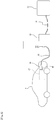
- a filling hose 45 and so on is filled hydrogen after a nozzle 30 and a receptacle 40 as a vehicle side filling port are connected with each other, and the filling is performed while being controlled depending on the maximum using pressure of a hydrogen tank 47 mounted in a vehicle A.
- the numeral 51 shows a piping system for feeding hydrogen from the hydrogen storage tank 50 to the dispenser 60.
- the present applicant has been already proposed the hydrogen filling device described above (refer to Japanese patent publication No. 2014-109350 gazette for example).
- the hydrogen filling device is effective, but when hydrogen gas is filled to a vehicle, seal structures are required to make insides of the filling nozzle and the vehicle side filling port airtight state.
- opening/closing a valve mechanism including a valve element 33 connected to a rod 32 of the nozzle 30 and a valve seat 31B that is a step portion of an in-pipe-joint passage 31A of the nozzle 30 performs filling/stopping of hydrogen gas.
- a valve mechanism including a valve element 33 connected to a rod 32 of the nozzle 30 and a valve seat 31B that is a step portion of an in-pipe-joint passage 31A of the nozzle 30 performs filling/stopping of hydrogen gas.
- a lever 35 is located radially outside the swelling portion 34A at an end of the clutch 34, unless the lever 35 moves in a direction that being separated from the receptacle 40 (left side in Fig. 6 ), the clutch 34 cannot be detached from the engaging channel 40B. Then, to prevent the lever 35 from moving in the direction that the lever 35 departs from the receptacle 40 (left side in Fig. 6 ) at filling, a lever holding mechanism 36 for maintaining a connection state between the pipe joint 31 of the filling nozzle 30 and the receptacle 40 is mounted on the pipe joint 31.
- the rod 32 is formed to be hollow, so that hydrogen gas passing through the valve mechanism flows in an in-rod passage 32B via openings 32A of the rod 32 to inflow into a passage 40C in the receptacle 40. Then, in order to prevent the hydrogen gas from leaking from a gap ⁇ between a radially outer periphery of the rod 32 and the in-pipe-joint passage 31A, a nozzle side O-ring 37 is mounted in the in-pipe-joint passage 31A as a sealing structure.
- a receptacle side O-ring 41 is mounted in the engaging recessed portion 40A as a sealing structure.
- the sealing structure with the nozzle side O-ring 37 and the receptacle side O-ring 41 becomes a resistance when the pipe joint 31 and the receptacle 40 (vehicle side filling port) are attached to each other and detached from each other.
- hydrogen gas is filled to vehicles with the same filling nozzle 30, so that when the number of filling operations increases, the sealing structure deteriorates, and there is a possibility that hydrogen gas leaks.
- the rod 32 slides on the nozzle side O-ring 37 and the receptacle side O-ring 41, so that repeating attachment/detachment between the filling nozzle 30 and the vehicle side filling port 40 causes the nozzle side O-ring 37 and the receptacle side O-ring 41 to deteriorate due to the slide of the rod 32 thereon, which may cause leakage of hydrogen gas.
- the present invention has been made in consideration of the above problems in the prior art, and the object thereof is to provide a filling device capable of preventing a seal structure from deteriorating and decreasing a risk that hydrogen gas leaks.
- Filling devices (100, 101) include a storage tank for storing hydrogen fuel and filling nozzles (10, 11) for filling hydrogen from the storage tank through a fuel filling system including a dispenser, a filling hose and so on to an in-vehicle hydrogen filling tank mounted on a vehicle, and a rod (2: valve rod) having a valve element at an end, the rod (2) slidably arranged against an elastic member (3) in a pipe joint main body (1) of the filling nozzles (10, 11), and are characterized in that in an end portion of the pipe joint main body (1) on a side of the in-vehicle hydrogen filling tank, an innermost portion for forming surface on which the rod (2) slides projects on the side of the in-vehicle hydrogen filling tank, and when the filling nozzles (10, 11) are connected to a vehicle side filling port (20: receptacle) of the in-vehicle hydrogen filling tank, an outer surface of the projecting portion (1E) of the pipe joint main
- a sealing structure is arranged in a portion where an inner periphery of the vehicle side filling port (20) contacts an outer periphery of the projecting portion (1E) of the pipe joint main body (1).
- the filling devices (100, 101) include a clutch mechanism (12) for maintaining a connected state between the filling nozzle (10) and the vehicle side filling port (20).
- contacting another end of the rod (2) to the vehicle side filling port (20) allows a passage (2B) in the filling nozzles (10, 11) to open, that is, connections of the filling nozzles (10, 11) to the vehicle side filling port (20) enable filling, so it is safe.
- arranging a sealing structure in a portion where an inner periphery of the vehicle side filling port (20) contacts an outer periphery of the projecting portion (1E) of the pipe joint main body (1) can prevent leakage of the hydrogen gas at filling of the hydrogen gas. Further, arranging a sealing structure in a portion of the vehicle side filling port (20) where contacting an outer periphery of the projecting portion (1E) of the pipe joint main body (1) can prevent leakage of the hydrogen gas from a gap ⁇ 1 between the portion of the vehicle side filling port (20) where contacting the outer periphery of the projecting portion (1E) of the pipe joint main body (1) and the outer periphery of the projecting portion (1E) of the pipe joint main body (1).
- the lever holding mechanism (36) of the filling nozzle (30) according to the conventional technique that maintains a connected state between the filling nozzle (30) and the vehicle side filling port (40) while hydrogen gas is filled is provided with a branched passage (36A) branched from the in-pipe-joint passage (31A), a lever holding slide member (36B) for slidably moving in the branched passage (36A), and a lever holding O-ring (36C). While the hydrogen gas is filled, pressure of the hydrogen gas flowing in the in-pipe-joint passage (31A) acts to the branched passage (36A), which causes the lever holding slide member (36B) to fall in Fig. 6 .
- the filling devices (100, 101) include a clutch mechanism (12) for maintaining a connected state between the filling nozzle (10) and the vehicle side filling port (20), the filling nozzle (10) cannot be detached in a pressurized state.
- the clutch mechanism (12) it is unnecessary, for example, to form the branched passage (36A) shown in Fig.6 ; the slide member (36B) is not required to slide in the branched passage (36A); and the sealing structure (O-ring 36C) is not required to be provided in the branched passage (36A).
- the branched passage (36A) constituting the lever holding mechanism (36) in the prior art.
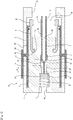
- a filling nozzle 10 fills hydrogen from a hydrogen fuel storage tank not shown through a fuel filling system including a dispenser 60, a filling hose 45 and so on to an in-vehicle hydrogen filling tank.
- the filling nozzle 10 has a pipe joint main body 1, and on a central portion (a central portion in a vertical direction in Fig. 1 ) of a hydrogen supply source side (left side in Fig. 1 ) end of the pipe joint main body 1 is formed a hydrogen introducing port 1B connected to a filling hose side (not shown).
- a receptacle side vehicle side filling port side, right side in Fig. 1
- an opening 1C for inserting a receptacle 20 (shown in Fig. 2 ) therein.
- a hydrogen supply source side left side in Fig. 1
- a receptacle insertion space 1D On a hydrogen supply source side (left side in Fig. 1 ) from the opening 1C in the pipe joint main body 1 is formed a receptacle insertion space 1D, when hydrogen is filled, the receptacle 20 is inserted into the pipe joint main body 1 (left side in Fig. 1 ) side from the opening 1C, and is situated in the receptacle insertion space 1D.
- a central portion in a vertical direction of the pipe joint main body 1 is formed an in-pipe-joint passage 1A, and the in-pipe-joint passage 1A extends from an opening 1B on the hydrogen supply source side to the space 1D on the receptacle side (extends from the left region to the right region in Fig.1 ).
- a receptacle (vehicle side filling port) side (right side in Fig. 1 ) of the pipe joint main body 1 projects a hollow pipe joint middle projection 1E, and the pipe joint middle projection 1E forms an end of the in-pipe-joint passage 1A on the receptacle side.
- in-pipe-joint passage 1A extending in a horizontal direction in Fig. 1 are formed two enlarged regions that are a valve element accommodating portion 1F and an enlarged diameter portion 1G.
- a rod 2 On an end of the rod 2 is mounted a valve element 2A, and the valve element 2A is accommodated in the valve element accommodating portion 1F of the in-pipe-joint passage 1A.
- a spring 3 On the hydrogen supply source side (left side in Fig. 1 ) from the valve element 2A is arranged a spring 3 as an elastic member.
- the rod 2 can slide in the in-pipe-joint passage 1A (in a horizontal direction in Fig. 1 ), and in a condition shown in Fig. 1 , that is, in a condition that the pipe joint main body 1 is not connected to the receptacle 20 (shown in Fig. 2 ), the valve element 2A is urged by an elastically repulsive force of the spring 3 to the receptacle side (right side in Fig. 1 ), and seats on a valve seat 1H constituted by a step portion at an end (right end portion in Fig. 1 ) of the valve element accommodating portion 1F.
- a valve seat 1H constituted by a step portion at an end (right end portion in Fig. 1 ) of the valve element accommodating portion 1F.
- Fig.1 in case that the pipe joint main body 1 is not connected to the receptacle 20 (shown in Fig.
- an end of the receptacle side (right side portion in Fig. 1 ) of the rod 2 projects on the receptacle side (right side in Fig. 1 ) from the receptacle side end portion of the pipe joint middle projection 1E.
- a region that the rod 2 projects from the pipe joint middle projection 1E is shown with the symbol TA.
- projecting amount (projecting length) of the region TA is determined based on a distance that the rod 2 moves to the left side in Fig. 1 (a direction apart from the receptacle 20) while hydrogen is filled and so on (refer to Fig. 2 ).
- the rod 2 has a hollow portion, and the hollow portion forms an in-rod passage 2B.
- the small-diameter portion 2C connected to the valve element 2A and the large-diameter portion 2D forming the hollow portion are connected by a diameter changing portion 2F forming the openings 2E.
- the diameter changing portion 2F of the rod 2 is accommodated in the enlarged diameter portion 1G of the in-pipe-joint passage 1A. While hydrogen gas is filled (refer to Fig. 2 ), from a dispenser not shown in Fig. 1 (refer to Fig. 5 : arranged in the left side region in Fig.
- a receptacle side end surface (right end surface in Fig. 1 ) of the diameter changing portion 2F of the rod 2 abuts against a step portion 1I of the enlarged diameter portion 1G of the in-pipe-joint passage 1A. But, the receptacle side end surface of the diameter changing portion 2F and the step portion 1I of the enlarged diameter portion 1G of the in-pipe-joint passage 1A do not have a function as an opening/closing valve.
- a clutch 4 with a hollow cylinder shape.
- a locking portion 4A projecting radially inward, and the locking portion 4A engages a clutch engaging channel 1J formed on the pipe joint main body 1 to be fixed thereto.
- a swelling portion 4B swelling radially outward and inward to be a thicker portion.
- a lever 5 Outside the clutch 4 in a radial direction is mounted a lever 5.
- the lever 5 is integrally formed with a lever grasping portion 5A, and moving the lever 5 in a direction of the arrow H while grasping the lever grasping portion 5A causes an end portion of the lever 5 on the receptacle side (right side in Fig. 1 ) to be positioned radially outside the swelling portion 4B of the clutch 4, which can prevent the swelling portion 4B of the clutch 4 from detaching from the engaging channel 20A ( Fig. 2 ) of the receptacle 20.
- a lever opening portion 1K for allowing the lever 5 to move in a direction of the allow H and a lever movement passage 1L.
- a crutch mechanism 12 for holding the lever 5 outside the swelling portion 4B of the clutch 4 at the connection of the filling nozzle 10 and the receptacle 20 ( Fig. 2 : when hydrogen is fed) will be explained below in detail.
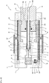
- Fig. 2 showing a condition that the filling nozzle 10 (the pipe joint main body 1) and the receptacle 20 are connected with each other, the receptacle 20 is inserted into the receptacle insertion space 1D in the pipe joint main body 1 from the opening 1C of the pipe joint main body 1.
- the projecting region TA of the rod 2 projects on the receptacle 20 side from the pipe joint middle projection 1E, but in the connected condition shown in Fig.
- the projecting region TA of the rod 2 contacts the bottom portion 20C of the engaging recessed portion of the receptacle 20 to be pressed, and the whole rod 2 moves left (the direction separating from the receptacle 20) in Figs. 1 and 2 from the condition shown in Fig. 1 .
- the rod 2 moves left by the projecting amount thereof shown in Fig. 1 until an end portion (right end) of the projecting region TA on the receptacle side (refer to Fig. 1 ) reaches the receptacle side end portion (right end) of the pipe joint middle projection 1E.
- the valve element 2A at an end of the rod 2 departs from the valve seat 1H against elastically repulsive force of the spring 3. Then, from a gap between the valve seat 1H and the valve element 2A, hydrogen gas inflows into the in-pipe-joint passage 1A.
- the hydrogen gas inflowing into the in-pipe-joint passage 1A is fed through the openings 2E, the in-rod passage 2B of the rod 2 and the in-receptacle passage 20B into the in-vehicle hydrogen filling tank 41 ( Fig. 5 ) not shown in Fig. 2 .
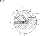
- the receptacle side O-ring 21 On a portion where the inner peripheral surface 20D of the engaging recessed portion of the receptacle 20 contacts the outer periphery of the pipe joint middle projection 1E is mounted the receptacle side O-ring 21. Even if there is hydrogen gas that flows from the bottom portion 20C of the receptacle engaging recessed portion to a gap ⁇ 1 between the inner wall surface 20D of the receptacle engaging recessed portion and the outer peripheral surface of the pipe joint middle projection 1E, the hydrogen gas is blocked by the receptacle side O-ring 21, so that the hydrogen gas does not leak outside the pipe joint main body 1.
- the rod 2 slides on the in-pipe-joint passage 1A, but hydrogen gas does not leak outside the pipe joint main body 1 even if no O-ring is mounted on a portion where the rod 2 slides.
- the valve element 2A seats on the valve seat 1H, so that into the in-pipe-joint passage 1A does not inflow hydrogen gas, and there is no possibility that hydrogen gas leaks from the gap between the pipe joint main body 1 and the receptacle 20.
- the hydrogen gas flowing in the in-pipe-joint passage 1A flows into the in-rod passage 2B or the gap ⁇ 1 between the outer peripheral surface of the rod large-diameter portion 2D and the inner peripheral surface of the in-pipe-joint passage 1A to reach the bottom portion 20C of the receptacle engaging recessed portion and flow into the in-receptacle passage 20B, so that the hydrogen gas does not leak outside the pipe joint main body 1 and the receptacle 20.
- the clutch mechanism 12 for holding the lever 5 to prevent the swelling portion 4B of the clutch 4 from detaching from the engaging channel 20A of the receptacle 20 when the filling nozzle 10 and the receptacle 20 are connected with each other (when hydrogen is fed). But, the mechanism does not exist in Fig. 6 .
- the clutch mechanism 12 has a function of holding a receptacle side end portion of the lever 5 outside the swelling portion 4B of the clutch 4 in a radial direction, and preventing the clutch 4 from detaching from the engaging channel 20A of the receptacle 20.
- the clutch mechanism 12 includes the projection 5B (projection of the lever) formed on the receptacle side (right side in Figs. 1 and 2 ) end portion of the lever 5 and a ring-shaped elastic member 6 (O-ring for example) disposed on the side separated from the receptacle 20 from the projection 5B of the lever 5.
- the projection 5B formed on the receptacle side end portion of the lever 5 projects radially inward.
- the ring-shaped elastic member 6 fits in an elastic body channel 5C formed near the receptacle side end portion of the lever 5.
- a radially outward force RO acts on the clutch 4 as a component force of the tensile force F1 to move the clutch 4 outward in a radial direction.
- the lever 5 does not move, so that the lever 5 continues positioning outward the swelling portion 4B of the clutch 4 in a radial direction to prevent the clutch 4 from moving outward in a radial direction. Therefore, without detaching the swelling portion 4B of the clutch 4 from the engaging channel 20A of the receptacle 20, it is prevented that the connection between the pipe joint main body 1 and the receptacle 20 is released.
- to exhibit action effect described above is properly designed elastic coefficient of the elastic member 6, projecting amount of the elastic member 6 to the crutch 4, projecting amount of the projection 5B of the lever 5 to the crutch 4, inclination angle of the inclined surface 4BA of the swelling portion 4B ( Figs. 2 and 3 ), inclination angle of the inclined surface 20AA of the receptacle engaging channel 20A ( Figs. 2 and 3 ), and so on.
- the lever 5 does not position outward the swelling portion 4B of the clutch 4 in a radial direction, and it becomes possible that the swelling portion 4B of the clutch 4 detaches from the engaging channel 20A of the receptacle 20. Then, the connection between the pipe joint main body 1 and the receptacle 20 can be released.
- the clutch mechanism 12 for holding the lever 5 and preventing the clutch 4 from detaching from the engaging channel 20A of the receptacle 20 has a different structure from the lever holding mechanism 36 shown in Fig. 6 , and it is unnecessary to mount the branched passage 36A branched from the in-pipe-joint passage 31A and the member 36B for sliding in the branched passage (lever holding slide member shown in Fig. 6 ), and to mount the O-ring 36C (lever holding O-ring) to the member. Therefore, it is prevented that the O-ring mounted on the mechanism for holding lever deteriorates to leak hydrogen gas.
- a receptacle side O-ring 21 on a portion where the inner peripheral surface 20D contacts the outer periphery of the pipe joint middle projection 1E, so that while hydrogen gas is filled, the hydrogen gas is prevented from leaking from the gap ⁇ 1 between a portion where the receptacle 20 contacts the outer periphery of the pipe joint main body 1 and the outer periphery of the pipe joint main body 1.
- the clutch mechanism 12 for maintaining a connected state between the filling nozzle 10 and the receptacle 20 (vehicle side filling port) is mounted, and when hydrogen is filled after the filling nozzle 10 and the receptacle 20 are connected with each other, the clutch 4 squeezes the elastic member 6 in a radial direction to contact the end surface 4BB of the swelling portion 4B of the clutch 4 and the end surface 5BA of the projection 5B of the lever 5 with each other, so that the lever 5 cannot move in a direction separating from the receptacle 20. Therefore, while hydrogen is filled after the filling nozzle 10 and the receptacle 20 are connected with each other, the filling nozzle 10 cannot be detached from the receptacle 20.
- Figure 4 shows the second embodiment of the present invention.
- a filling nozzle 11 of the second embodiment shown in Fig. 4 differs from the filling nozzle 10 of the first embodiment shown in Figs. 1 to 3 in a clutch mechanism (lever holding mechanism).
- the second embodiment are not mounted the projection 5B (projection of lever) mounted on the receptacle side (right side in Figs. 1 and 2 ) end portion of the lever 5 and the ring-shaped elastic member 6 (O-ring for example) mounted on the side (left side in Figs. 1 and 2 ) separating from the receptacle 20 from the projection 5B of the lever 5 like the first embodiment as shown in Figs. 1 and 2 .
- the lever holding mechanism of the second embodiment is constructed as same as that shown in Fig. 6 , and has a function of holding the lever 35 outward the swelling portion 34A of the clutch 34 and preventing the swelling portion 34A of the clutch 34 from detaching from the engaging channel 20A of the receptacle 20 while the filling nozzle 11 and the receptacle 20 are connected with each other. Since construction and action effect of the lever holding mechanism are the same as those of the mechanism shown in Fig. 6 , repeated explanation is omitted.
- to members constructing the lever holding mechanism 36 are attached the same numerals as those in Fig. 6 .
- the other members shown in Fig. 4 constructed as same as those shown in Figs. 1 to 3 are attached the same numerals as Figs. 1 to 3 .
- a sealing structure is arranged on a portion where the rod 2 slides the in-pipe-joint passage 1A, so that the seal structure (O-ring) can be prevented from deterioration due to the slide of the rod 2. Therefore, leakage of hydrogen gas due to deterioration of the sealing structure (O-ring) can be prevented.
- Other construction and action effect in the second embodiment shown in Fig. 4 are the same as those in the first embodiment shown in Figs. 1 to 3 .
Landscapes
- Engineering & Computer Science (AREA)
- General Engineering & Computer Science (AREA)
- Mechanical Engineering (AREA)
- Sustainable Energy (AREA)
- Sustainable Development (AREA)
- Life Sciences & Earth Sciences (AREA)
- Chemical & Material Sciences (AREA)
- Manufacturing & Machinery (AREA)
- Chemical Kinetics & Catalysis (AREA)
- Electrochemistry (AREA)
- General Chemical & Material Sciences (AREA)
- Combustion & Propulsion (AREA)
- Transportation (AREA)
- Filling Or Discharging Of Gas Storage Vessels (AREA)
Applications Claiming Priority (1)
| Application Number | Priority Date | Filing Date | Title |
|---|---|---|---|
| JP2016222998A JP6516207B2 (ja) | 2016-11-16 | 2016-11-16 | 充填装置 |
Publications (2)
| Publication Number | Publication Date |
|---|---|
| EP3324097A1 true EP3324097A1 (de) | 2018-05-23 |
| EP3324097B1 EP3324097B1 (de) | 2021-06-16 |
Family
ID=60161988
Family Applications (1)
| Application Number | Title | Priority Date | Filing Date |
|---|---|---|---|
| EP17197423.1A Active EP3324097B1 (de) | 2016-11-16 | 2017-10-20 | Füllvorrichtung |
Country Status (3)
| Country | Link |
|---|---|
| US (1) | US10442287B2 (de) |
| EP (1) | EP3324097B1 (de) |
| JP (1) | JP6516207B2 (de) |
Cited By (3)
| Publication number | Priority date | Publication date | Assignee | Title |
|---|---|---|---|---|
| EP3428505A1 (de) * | 2017-07-11 | 2019-01-16 | Tatsuno Corporation | Füllvorrichtung |
| CN109538925A (zh) * | 2018-12-03 | 2019-03-29 | 海宁市英德赛电子有限公司 | 高纯氨槽车自动化充装系统 |
| EP3719381A4 (de) * | 2018-02-09 | 2021-08-04 | Tatsuno Corporation | Füllvorrichtung |
Families Citing this family (10)
| Publication number | Priority date | Publication date | Assignee | Title |
|---|---|---|---|---|
| CN110848562B (zh) * | 2019-10-16 | 2024-07-02 | 北京航天试验技术研究所 | 一种液氢加注装置 |
| CN110864219B (zh) * | 2019-10-16 | 2024-06-28 | 北京航天试验技术研究所 | 一种液氢加注装置 |
| KR102277328B1 (ko) * | 2020-03-10 | 2021-07-14 | 하이리움산업(주) | 액화수소 충전장치 |
| FR3119657A1 (fr) * | 2021-02-05 | 2022-08-12 | Staubli Faverges | Elément de raccord |
| CN114216051B (zh) * | 2021-11-12 | 2023-06-06 | 深圳安博信息科技有限公司 | 一种液化气充气枪 |
| JP7372606B2 (ja) * | 2022-01-05 | 2023-11-01 | 株式会社タツノ | 安全継手 |
| CN114383038B (zh) * | 2022-03-24 | 2022-05-24 | 四川凯德源科技有限公司 | 一种氢能汽车加氢充装用机械手臂 |
| CN114552102B (zh) * | 2022-04-25 | 2022-07-12 | 武汉东湖学院 | 一种光伏发电用蓄电池安装保护装置 |
| JP7704173B2 (ja) * | 2023-05-16 | 2025-07-08 | 株式会社タツノ | 充填ノズル |
| JP7827084B2 (ja) | 2024-03-06 | 2026-03-10 | 株式会社タツノ | 充填ノズル |
Citations (4)
| Publication number | Priority date | Publication date | Assignee | Title |
|---|---|---|---|---|
| US6343630B1 (en) * | 1998-05-22 | 2002-02-05 | Delaware Capital Formation, Inc. | High pressure filling nozzle |
| EP1437543A1 (de) * | 2002-12-18 | 2004-07-14 | Witt-Gasetechnik GmbH & Co. KG | Schnellanschlusskupplung mit Betätigungseinrichtung für die Übertragung eines gasförmigen und /oder flüssigen Mediums |
| US20070155224A1 (en) * | 2004-01-19 | 2007-07-05 | Gerard Marot | System for connecting the ends of fluid conduits |
| JP2014109350A (ja) | 2012-12-04 | 2014-06-12 | Tatsuno Corp | ガス充填装置 |
Family Cites Families (8)
| Publication number | Priority date | Publication date | Assignee | Title |
|---|---|---|---|---|
| JP2003336795A (ja) * | 2002-03-13 | 2003-11-28 | Nippon Sanso Corp | 燃料充填装置および燃料漏れ検出方法 |
| JP2005098469A (ja) * | 2002-12-27 | 2005-04-14 | Hitachi Ltd | ガス充填カップリング |
| US7028724B2 (en) * | 2003-05-30 | 2006-04-18 | Air Products And Chemicals, Inc. | Fueling nozzle with integral molecular leak sensor |
| US7715169B2 (en) * | 2005-08-31 | 2010-05-11 | Steven R Mathison | Fuel receptacle isolation system for reducing the possibility of static discharge during the refill of high pressure storage tanks in motor vehicles |
| JP6057403B2 (ja) * | 2010-08-27 | 2017-01-11 | 国立研究開発法人産業技術総合研究所 | シール |
| EP2728241B1 (de) * | 2012-11-05 | 2016-02-03 | Magna Steyr Fahrzeugtechnik AG & Co KG | Tankstutzeneinheit mit Sperrventil |
| CA2919688A1 (en) * | 2013-08-02 | 2015-02-05 | Alternative Fuel Containers, Llc | Fuel gas tank filling system and method |
| JP6482238B2 (ja) * | 2014-11-04 | 2019-03-13 | 株式会社 イー・エス・プロジェクト | 手動型の充填器 |
-
2016
- 2016-11-16 JP JP2016222998A patent/JP6516207B2/ja active Active
-
2017
- 2017-09-26 US US15/715,671 patent/US10442287B2/en active Active
- 2017-10-20 EP EP17197423.1A patent/EP3324097B1/de active Active
Patent Citations (4)
| Publication number | Priority date | Publication date | Assignee | Title |
|---|---|---|---|---|
| US6343630B1 (en) * | 1998-05-22 | 2002-02-05 | Delaware Capital Formation, Inc. | High pressure filling nozzle |
| EP1437543A1 (de) * | 2002-12-18 | 2004-07-14 | Witt-Gasetechnik GmbH & Co. KG | Schnellanschlusskupplung mit Betätigungseinrichtung für die Übertragung eines gasförmigen und /oder flüssigen Mediums |
| US20070155224A1 (en) * | 2004-01-19 | 2007-07-05 | Gerard Marot | System for connecting the ends of fluid conduits |
| JP2014109350A (ja) | 2012-12-04 | 2014-06-12 | Tatsuno Corp | ガス充填装置 |
Cited By (5)
| Publication number | Priority date | Publication date | Assignee | Title |
|---|---|---|---|---|
| EP3428505A1 (de) * | 2017-07-11 | 2019-01-16 | Tatsuno Corporation | Füllvorrichtung |
| US10625599B2 (en) | 2017-07-11 | 2020-04-21 | Tatsuno Corporation | Filling apparatus |
| EP3719381A4 (de) * | 2018-02-09 | 2021-08-04 | Tatsuno Corporation | Füllvorrichtung |
| US11193631B2 (en) | 2018-02-09 | 2021-12-07 | Tatsuno Corporation | Filling device |
| CN109538925A (zh) * | 2018-12-03 | 2019-03-29 | 海宁市英德赛电子有限公司 | 高纯氨槽车自动化充装系统 |
Also Published As
| Publication number | Publication date |
|---|---|
| EP3324097B1 (de) | 2021-06-16 |
| JP2018080745A (ja) | 2018-05-24 |
| JP6516207B2 (ja) | 2019-05-22 |
| US20180134147A1 (en) | 2018-05-17 |
| US10442287B2 (en) | 2019-10-15 |
Similar Documents
| Publication | Publication Date | Title |
|---|---|---|
| EP3324097B1 (de) | Füllvorrichtung | |
| EP3324096B1 (de) | Füllvorrichtung | |
| EP3428505B1 (de) | Füllvorrichtung | |
| EP4023929B1 (de) | Füllvorrichtung | |
| US20140174594A1 (en) | Filling connector, container, filling method and filling nozzle | |
| US10598294B2 (en) | Safety joint for a fluid filling apparatus | |
| EP3333469B1 (de) | Rohrverbindung | |
| US11193631B2 (en) | Filling device | |
| US11092273B2 (en) | Coupling for transferring fluids, method for closing the fluid duct of such a coupling, and preferred use of this coupling | |
| US20190271409A1 (en) | Valve body having primary and secondary stem guides | |
| KR20090102425A (ko) | 가스용기 탭의 체크밸브 | |
| US10480682B2 (en) | Strainer assembly for internal valve | |
| US11859747B2 (en) | Safety joint | |
| CN108571608B (zh) | 内部阀的过滤器组件 |
Legal Events
| Date | Code | Title | Description |
|---|---|---|---|
| PUAI | Public reference made under article 153(3) epc to a published international application that has entered the european phase |
Free format text: ORIGINAL CODE: 0009012 |
|
| STAA | Information on the status of an ep patent application or granted ep patent |
Free format text: STATUS: THE APPLICATION HAS BEEN PUBLISHED |
|
| AK | Designated contracting states |
Kind code of ref document: A1 Designated state(s): AL AT BE BG CH CY CZ DE DK EE ES FI FR GB GR HR HU IE IS IT LI LT LU LV MC MK MT NL NO PL PT RO RS SE SI SK SM TR |
|
| AX | Request for extension of the european patent |
Extension state: BA ME |
|
| STAA | Information on the status of an ep patent application or granted ep patent |
Free format text: STATUS: REQUEST FOR EXAMINATION WAS MADE |
|
| 17P | Request for examination filed |
Effective date: 20181024 |
|
| RBV | Designated contracting states (corrected) |
Designated state(s): AL AT BE BG CH CY CZ DE DK EE ES FI FR GB GR HR HU IE IS IT LI LT LU LV MC MK MT NL NO PL PT RO RS SE SI SK SM TR |
|
| GRAP | Despatch of communication of intention to grant a patent |
Free format text: ORIGINAL CODE: EPIDOSNIGR1 |
|
| STAA | Information on the status of an ep patent application or granted ep patent |
Free format text: STATUS: GRANT OF PATENT IS INTENDED |
|
| INTG | Intention to grant announced |
Effective date: 20210112 |
|
| GRAS | Grant fee paid |
Free format text: ORIGINAL CODE: EPIDOSNIGR3 |
|
| GRAA | (expected) grant |
Free format text: ORIGINAL CODE: 0009210 |
|
| STAA | Information on the status of an ep patent application or granted ep patent |
Free format text: STATUS: THE PATENT HAS BEEN GRANTED |
|
| AK | Designated contracting states |
Kind code of ref document: B1 Designated state(s): AL AT BE BG CH CY CZ DE DK EE ES FI FR GB GR HR HU IE IS IT LI LT LU LV MC MK MT NL NO PL PT RO RS SE SI SK SM TR |
|
| REG | Reference to a national code |
Ref country code: GB Ref legal event code: FG4D |
|
| REG | Reference to a national code |
Ref country code: CH Ref legal event code: EP |
|
| REG | Reference to a national code |
Ref country code: DE Ref legal event code: R096 Ref document number: 602017040289 Country of ref document: DE Ref country code: AT Ref legal event code: REF Ref document number: 1402620 Country of ref document: AT Kind code of ref document: T Effective date: 20210715 |
|
| REG | Reference to a national code |
Ref country code: IE Ref legal event code: FG4D |
|
| REG | Reference to a national code |
Ref country code: LT Ref legal event code: MG9D |
|
| PG25 | Lapsed in a contracting state [announced via postgrant information from national office to epo] |
Ref country code: FI Free format text: LAPSE BECAUSE OF FAILURE TO SUBMIT A TRANSLATION OF THE DESCRIPTION OR TO PAY THE FEE WITHIN THE PRESCRIBED TIME-LIMIT Effective date: 20210616 Ref country code: LT Free format text: LAPSE BECAUSE OF FAILURE TO SUBMIT A TRANSLATION OF THE DESCRIPTION OR TO PAY THE FEE WITHIN THE PRESCRIBED TIME-LIMIT Effective date: 20210616 Ref country code: BG Free format text: LAPSE BECAUSE OF FAILURE TO SUBMIT A TRANSLATION OF THE DESCRIPTION OR TO PAY THE FEE WITHIN THE PRESCRIBED TIME-LIMIT Effective date: 20210916 Ref country code: HR Free format text: LAPSE BECAUSE OF FAILURE TO SUBMIT A TRANSLATION OF THE DESCRIPTION OR TO PAY THE FEE WITHIN THE PRESCRIBED TIME-LIMIT Effective date: 20210616 |
|
| REG | Reference to a national code |
Ref country code: AT Ref legal event code: MK05 Ref document number: 1402620 Country of ref document: AT Kind code of ref document: T Effective date: 20210616 |
|
| REG | Reference to a national code |
Ref country code: NL Ref legal event code: MP Effective date: 20210616 |
|
| PG25 | Lapsed in a contracting state [announced via postgrant information from national office to epo] |
Ref country code: NO Free format text: LAPSE BECAUSE OF FAILURE TO SUBMIT A TRANSLATION OF THE DESCRIPTION OR TO PAY THE FEE WITHIN THE PRESCRIBED TIME-LIMIT Effective date: 20210916 Ref country code: RS Free format text: LAPSE BECAUSE OF FAILURE TO SUBMIT A TRANSLATION OF THE DESCRIPTION OR TO PAY THE FEE WITHIN THE PRESCRIBED TIME-LIMIT Effective date: 20210616 Ref country code: SE Free format text: LAPSE BECAUSE OF FAILURE TO SUBMIT A TRANSLATION OF THE DESCRIPTION OR TO PAY THE FEE WITHIN THE PRESCRIBED TIME-LIMIT Effective date: 20210616 Ref country code: GR Free format text: LAPSE BECAUSE OF FAILURE TO SUBMIT A TRANSLATION OF THE DESCRIPTION OR TO PAY THE FEE WITHIN THE PRESCRIBED TIME-LIMIT Effective date: 20210917 Ref country code: LV Free format text: LAPSE BECAUSE OF FAILURE TO SUBMIT A TRANSLATION OF THE DESCRIPTION OR TO PAY THE FEE WITHIN THE PRESCRIBED TIME-LIMIT Effective date: 20210616 |
|
| PG25 | Lapsed in a contracting state [announced via postgrant information from national office to epo] |
Ref country code: SK Free format text: LAPSE BECAUSE OF FAILURE TO SUBMIT A TRANSLATION OF THE DESCRIPTION OR TO PAY THE FEE WITHIN THE PRESCRIBED TIME-LIMIT Effective date: 20210616 Ref country code: SM Free format text: LAPSE BECAUSE OF FAILURE TO SUBMIT A TRANSLATION OF THE DESCRIPTION OR TO PAY THE FEE WITHIN THE PRESCRIBED TIME-LIMIT Effective date: 20210616 Ref country code: AT Free format text: LAPSE BECAUSE OF FAILURE TO SUBMIT A TRANSLATION OF THE DESCRIPTION OR TO PAY THE FEE WITHIN THE PRESCRIBED TIME-LIMIT Effective date: 20210616 Ref country code: EE Free format text: LAPSE BECAUSE OF FAILURE TO SUBMIT A TRANSLATION OF THE DESCRIPTION OR TO PAY THE FEE WITHIN THE PRESCRIBED TIME-LIMIT Effective date: 20210616 Ref country code: ES Free format text: LAPSE BECAUSE OF FAILURE TO SUBMIT A TRANSLATION OF THE DESCRIPTION OR TO PAY THE FEE WITHIN THE PRESCRIBED TIME-LIMIT Effective date: 20210616 Ref country code: RO Free format text: LAPSE BECAUSE OF FAILURE TO SUBMIT A TRANSLATION OF THE DESCRIPTION OR TO PAY THE FEE WITHIN THE PRESCRIBED TIME-LIMIT Effective date: 20210616 Ref country code: PT Free format text: LAPSE BECAUSE OF FAILURE TO SUBMIT A TRANSLATION OF THE DESCRIPTION OR TO PAY THE FEE WITHIN THE PRESCRIBED TIME-LIMIT Effective date: 20211018 Ref country code: NL Free format text: LAPSE BECAUSE OF FAILURE TO SUBMIT A TRANSLATION OF THE DESCRIPTION OR TO PAY THE FEE WITHIN THE PRESCRIBED TIME-LIMIT Effective date: 20210616 |
|
| PG25 | Lapsed in a contracting state [announced via postgrant information from national office to epo] |
Ref country code: PL Free format text: LAPSE BECAUSE OF FAILURE TO SUBMIT A TRANSLATION OF THE DESCRIPTION OR TO PAY THE FEE WITHIN THE PRESCRIBED TIME-LIMIT Effective date: 20210616 |
|
| REG | Reference to a national code |
Ref country code: DE Ref legal event code: R097 Ref document number: 602017040289 Country of ref document: DE |
|
| PLBE | No opposition filed within time limit |
Free format text: ORIGINAL CODE: 0009261 |
|
| STAA | Information on the status of an ep patent application or granted ep patent |
Free format text: STATUS: NO OPPOSITION FILED WITHIN TIME LIMIT |
|
| PG25 | Lapsed in a contracting state [announced via postgrant information from national office to epo] |
Ref country code: DK Free format text: LAPSE BECAUSE OF FAILURE TO SUBMIT A TRANSLATION OF THE DESCRIPTION OR TO PAY THE FEE WITHIN THE PRESCRIBED TIME-LIMIT Effective date: 20210616 |
|
| 26N | No opposition filed |
Effective date: 20220317 |
|
| PG25 | Lapsed in a contracting state [announced via postgrant information from national office to epo] |
Ref country code: AL Free format text: LAPSE BECAUSE OF FAILURE TO SUBMIT A TRANSLATION OF THE DESCRIPTION OR TO PAY THE FEE WITHIN THE PRESCRIBED TIME-LIMIT Effective date: 20210616 |
|
| REG | Reference to a national code |
Ref country code: BE Ref legal event code: MM Effective date: 20211031 |
|
| PG25 | Lapsed in a contracting state [announced via postgrant information from national office to epo] |
Ref country code: MC Free format text: LAPSE BECAUSE OF FAILURE TO SUBMIT A TRANSLATION OF THE DESCRIPTION OR TO PAY THE FEE WITHIN THE PRESCRIBED TIME-LIMIT Effective date: 20210616 |
|
| PG25 | Lapsed in a contracting state [announced via postgrant information from national office to epo] |
Ref country code: LU Free format text: LAPSE BECAUSE OF NON-PAYMENT OF DUE FEES Effective date: 20211020 Ref country code: BE Free format text: LAPSE BECAUSE OF NON-PAYMENT OF DUE FEES Effective date: 20211031 |
|
| PG25 | Lapsed in a contracting state [announced via postgrant information from national office to epo] |
Ref country code: IE Free format text: LAPSE BECAUSE OF NON-PAYMENT OF DUE FEES Effective date: 20211020 |
|
| PG25 | Lapsed in a contracting state [announced via postgrant information from national office to epo] |
Ref country code: HU Free format text: LAPSE BECAUSE OF FAILURE TO SUBMIT A TRANSLATION OF THE DESCRIPTION OR TO PAY THE FEE WITHIN THE PRESCRIBED TIME-LIMIT; INVALID AB INITIO Effective date: 20171020 |
|
| PG25 | Lapsed in a contracting state [announced via postgrant information from national office to epo] |
Ref country code: CY Free format text: LAPSE BECAUSE OF FAILURE TO SUBMIT A TRANSLATION OF THE DESCRIPTION OR TO PAY THE FEE WITHIN THE PRESCRIBED TIME-LIMIT Effective date: 20210616 |
|
| PG25 | Lapsed in a contracting state [announced via postgrant information from national office to epo] |
Ref country code: MK Free format text: LAPSE BECAUSE OF FAILURE TO SUBMIT A TRANSLATION OF THE DESCRIPTION OR TO PAY THE FEE WITHIN THE PRESCRIBED TIME-LIMIT Effective date: 20210616 |
|
| PG25 | Lapsed in a contracting state [announced via postgrant information from national office to epo] |
Ref country code: MT Free format text: LAPSE BECAUSE OF FAILURE TO SUBMIT A TRANSLATION OF THE DESCRIPTION OR TO PAY THE FEE WITHIN THE PRESCRIBED TIME-LIMIT Effective date: 20210616 |
|
| REG | Reference to a national code |
Ref country code: CH Ref legal event code: U11 Free format text: ST27 STATUS EVENT CODE: U-0-0-U10-U11 (AS PROVIDED BY THE NATIONAL OFFICE) Effective date: 20251101 |
|
| PG25 | Lapsed in a contracting state [announced via postgrant information from national office to epo] |
Ref country code: TR Free format text: LAPSE BECAUSE OF FAILURE TO SUBMIT A TRANSLATION OF THE DESCRIPTION OR TO PAY THE FEE WITHIN THE PRESCRIBED TIME-LIMIT Effective date: 20210616 |
|
| PGFP | Annual fee paid to national office [announced via postgrant information from national office to epo] |
Ref country code: DE Payment date: 20251031 Year of fee payment: 9 |
|
| PGFP | Annual fee paid to national office [announced via postgrant information from national office to epo] |
Ref country code: GB Payment date: 20251022 Year of fee payment: 9 |
|
| PGFP | Annual fee paid to national office [announced via postgrant information from national office to epo] |
Ref country code: IT Payment date: 20251024 Year of fee payment: 9 |
|
| PGFP | Annual fee paid to national office [announced via postgrant information from national office to epo] |
Ref country code: FR Payment date: 20251030 Year of fee payment: 9 |
|
| PGFP | Annual fee paid to national office [announced via postgrant information from national office to epo] |
Ref country code: CH Payment date: 20251101 Year of fee payment: 9 |
|
| PGFP | Annual fee paid to national office [announced via postgrant information from national office to epo] |
Ref country code: CZ Payment date: 20251015 Year of fee payment: 9 |