EP3324162A1 - Dispositif de détection de corps humain - Google Patents
Dispositif de détection de corps humain Download PDFInfo
- Publication number
- EP3324162A1 EP3324162A1 EP17163871.1A EP17163871A EP3324162A1 EP 3324162 A1 EP3324162 A1 EP 3324162A1 EP 17163871 A EP17163871 A EP 17163871A EP 3324162 A1 EP3324162 A1 EP 3324162A1
- Authority
- EP
- European Patent Office
- Prior art keywords
- human body
- electrically connected
- detecting device
- microprocessor
- body detecting
- Prior art date
- Legal status (The legal status is an assumption and is not a legal conclusion. Google has not performed a legal analysis and makes no representation as to the accuracy of the status listed.)
- Withdrawn
Links
Images

Classifications
-
- G—PHYSICS
- G01—MEASURING; TESTING
- G01J—MEASUREMENT OF INTENSITY, VELOCITY, SPECTRAL CONTENT, POLARISATION, PHASE OR PULSE CHARACTERISTICS OF INFRARED, VISIBLE OR ULTRAVIOLET LIGHT; COLORIMETRY; RADIATION PYROMETRY
- G01J5/00—Radiation pyrometry, e.g. infrared or optical thermometry
- G01J5/02—Constructional details
- G01J5/06—Arrangements for eliminating effects of disturbing radiation; Arrangements for compensating changes in sensitivity
-
- A—HUMAN NECESSITIES
- A61—MEDICAL OR VETERINARY SCIENCE; HYGIENE
- A61B—DIAGNOSIS; SURGERY; IDENTIFICATION
- A61B5/00—Measuring for diagnostic purposes; Identification of persons
- A61B5/01—Measuring temperature of body parts ; Diagnostic temperature sensing, e.g. for malignant or inflamed tissue
-
- G—PHYSICS
- G01—MEASURING; TESTING
- G01J—MEASUREMENT OF INTENSITY, VELOCITY, SPECTRAL CONTENT, POLARISATION, PHASE OR PULSE CHARACTERISTICS OF INFRARED, VISIBLE OR ULTRAVIOLET LIGHT; COLORIMETRY; RADIATION PYROMETRY
- G01J5/00—Radiation pyrometry, e.g. infrared or optical thermometry
- G01J5/0022—Radiation pyrometry, e.g. infrared or optical thermometry for sensing the radiation of moving bodies
- G01J5/0025—Living bodies
-
- A—HUMAN NECESSITIES
- A61—MEDICAL OR VETERINARY SCIENCE; HYGIENE
- A61B—DIAGNOSIS; SURGERY; IDENTIFICATION
- A61B5/00—Measuring for diagnostic purposes; Identification of persons
- A61B5/0059—Measuring for diagnostic purposes; Identification of persons using light, e.g. diagnosis by transillumination, diascopy, fluorescence
-
- A—HUMAN NECESSITIES
- A61—MEDICAL OR VETERINARY SCIENCE; HYGIENE
- A61B—DIAGNOSIS; SURGERY; IDENTIFICATION
- A61B5/00—Measuring for diagnostic purposes; Identification of persons
- A61B5/72—Signal processing specially adapted for physiological signals or for diagnostic purposes
- A61B5/7225—Details of analogue processing, e.g. isolation amplifier, gain or sensitivity adjustment, filtering, baseline or drift compensation
-
- G—PHYSICS
- G01—MEASURING; TESTING
- G01J—MEASUREMENT OF INTENSITY, VELOCITY, SPECTRAL CONTENT, POLARISATION, PHASE OR PULSE CHARACTERISTICS OF INFRARED, VISIBLE OR ULTRAVIOLET LIGHT; COLORIMETRY; RADIATION PYROMETRY
- G01J5/00—Radiation pyrometry, e.g. infrared or optical thermometry
- G01J5/02—Constructional details
- G01J5/026—Control of working procedures of a pyrometer, other than calibration; Bandwidth calculation; Gain control
-
- G—PHYSICS
- G01—MEASURING; TESTING
- G01J—MEASUREMENT OF INTENSITY, VELOCITY, SPECTRAL CONTENT, POLARISATION, PHASE OR PULSE CHARACTERISTICS OF INFRARED, VISIBLE OR ULTRAVIOLET LIGHT; COLORIMETRY; RADIATION PYROMETRY
- G01J5/00—Radiation pyrometry, e.g. infrared or optical thermometry
- G01J5/02—Constructional details
- G01J5/06—Arrangements for eliminating effects of disturbing radiation; Arrangements for compensating changes in sensitivity
- G01J5/064—Ambient temperature sensor; Housing temperature sensor; Constructional details thereof
-
- G—PHYSICS
- G01—MEASURING; TESTING
- G01J—MEASUREMENT OF INTENSITY, VELOCITY, SPECTRAL CONTENT, POLARISATION, PHASE OR PULSE CHARACTERISTICS OF INFRARED, VISIBLE OR ULTRAVIOLET LIGHT; COLORIMETRY; RADIATION PYROMETRY
- G01J5/00—Radiation pyrometry, e.g. infrared or optical thermometry
- G01J5/10—Radiation pyrometry, e.g. infrared or optical thermometry using electric radiation detectors
- G01J5/34—Radiation pyrometry, e.g. infrared or optical thermometry using electric radiation detectors using capacitors, e.g. pyroelectric capacitors
-
- A—HUMAN NECESSITIES
- A61—MEDICAL OR VETERINARY SCIENCE; HYGIENE
- A61B—DIAGNOSIS; SURGERY; IDENTIFICATION
- A61B2562/00—Details of sensors; Constructional details of sensor housings or probes; Accessories for sensors
- A61B2562/02—Details of sensors specially adapted for in-vivo measurements
- A61B2562/0271—Thermal or temperature sensors
Definitions
- the present disclosure relates to non-contact measuring device. More particularly, the present disclosure relates to human body detecting device.
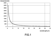
- Infrared radiation is an invisible radiant energy, electromagnetic radiation with longer wavelengths than those of visible light, extending from the nominal red edge of the visible spectrum at 0.7 micrometers to 1000 micrometers. Below infrared is the microwave portion of the electromagnetic spectrum. All matter with a temperature greater than absolute zero (-273K) emits infrared radiation, and the temperature determines the wavelength distribution of the infrared radiation. As shown in FIG. 1 , the wavelength of the infrared radiation is decreased when the temperature increases.
- a pyroelectric infrared radial (PIR) sensor is a non-contact measuring device configured to react to an infrared radiation having a wavelength of about 10 ⁇ m emitted from a human body, and may be formed using a lead zirconate titanate (PZT)-based material and a lithium tantalite (LiTaO 3 )-based material.
- PZT lead zirconate titanate
- LiTaO 3 lithium tantalite
- the PIR sensor may detect a human body through the pyroelectricity effect.
- the PIR sensor may sense infrared radiation at any wavelength; however, it is well known in the art to employ PIR sensor in automation fields, security fields, illumination systems, guest saluting apparatuses, infrared radiation spectrometers, and radiation detectors to measure the temperature of human body moving through the field of view of the PIR sensor; therefore, the commercial PIR sensor adapts a filter within the optical route to filter out short wavelengths of the sunlight and fluorescent light.
- the filter may be selected to have 70% optical transmittance for wavelengths of 8-12 ⁇ m for employing in measuring infrared radiation of human body.
- the PIR sensor is a passivate infrared radiation sensor, and has advantage of compact, low power and inexpensive. However, such sensor is not well-suited for use in the environment which the temperature is close to that of human body (such as in summer day). Under the condition aforementioned, the electronic signals generated by the PIR sensor are low and which may make the PIR sensor not to work properly.
- a human body detecting device includes a pyroelectric infrared radial (PIR) sensor, a thermometer, a processor, an amplifying unit, and a plurality of magnification adjusting units.
- the PIR sensor is configured to sense infrared radiation and then generate an electronic signal.
- the thermometer is configured to sense an ambient temperature and then generate a temperature value.
- the microprocessor is electrically connected to the thermometer, and the amplifying unit is electrically connected to the PIR sensor and the microprocessor.
- the magnification adjusting units corresponding to a plurality of temperature intervals are electrically connected to the microprocessor and the amplifying unit.
- the microprocessor selects to enable one of the magnification adjusting units based on a comparison between the temperature value and the temperature intervals, whereby the amplifying unit may modulate the electrical signal according to the enabled magnification adjusting unit.
- the amplifying unit may include a signal amplifier and a voltage-dividing resistor, the signal amplifier is electrically connected to the PIR sensor and the microprocessor, the voltage-dividing resistor is electrically connected to the signal amplifier and the magnification adjusting units.
- each magnification adjusting unit may include a resistor connected to the signal amplifier and a switch arranged between the resistor and ground, and an enabling end of the switch is connected to the microprocessor; when a resistance value of the resistor of the selected magnification adjusting unit is decreased, an amplification factor of the electronic signal and a value of a capacitance value of the capacitor increase.
- each magnification adjusting unit may further include a capacitor arranged between the resistor and the switch and electrically connected thereto; the capacitor may be a high-pass filtering capacitor and configurated to filter direct current (DC) signals.
- DC direct current
- the human body detecting device may further include a low-pass filtering capacitor electrically connected to the voltage-dividing resistor in parallel and configured to filter high-frequent noise.
- the human body detecting device may further include a power decoupling capacitor electrically connected to the PIR sensor and the signal amplifier and configured to filter noise, whereby stable operation can be performed.
- the human body detecting device further includes a static current controlling resistor electrically connected to the PIR sensor and the signal amplifier and configured to control the static current of the PIR sensor.
- the microprocessor and the thermometer are communicated directly with each other via an Inter-Integrated Circuit (I 2 C) bus communication protocol.
- I 2 C Inter-Integrated Circuit
- the human body detecting device is configured to detecting infrared radiation radiate from human body, and when a difference between the human temperature and ambient temperature is decreased, a magnification factor of the electronic signal increases.
- magnification adjusting units are electrically connected in parallel.
- the switch is an N-type bipolar transistor; the base of the switch is connected to the microprocessor, the collector thereof is connected to the resistor, and the emitter thereof is connected to ground.
- the human body detecting deice includes multiple magnification adjusting units, and the microprocessor may select to enable one of the magnification adjusting units based on the ambient temperature, thus the problem which the PIR sensor not work properly is overcome.
- a human body detecting device of the present disclosure includes a pyroelectric infrared radial (PIR) sensor, a thermometer, a processor, an amplifying unit, and a plurality of magnification adjusting units.
- the microprocessor selects to enable one of the magnification adjusting units, such that the amplifying unit may adjust magnification factor of an electrical signal detected by the PIR sensor according to the enabled magnification adjusting unit.
- each magnification adjusting unit includes a switch and a resistor.
- the enabling end of the switch is connected to the microprocessor, and the resistor is arranged between the amplifying unit and non-enabling end of the switch.
- the magnification adjusting units are designed to heavily magnify the electronic signal when the resistance value of the resistor of the selected magnification adjusting unit is low, and to slight amplify the electronic signal when the resistor value of the resistor of the selected magnification adjusting unit is high.
- Each magnification adjusting unit further includes a capacitor arranged between the switch and the resistor and electrically connected thereto for filtering direct current (DC) signal, wherein in the magnification adjusting units, the capacitance value of the capacitor is increased when the resistance value of the resistor electrically connected to the capacitor decreases, therefore, the problem which the PIR sensor not work properly is overcome
- the human body detecting device 1 includes a PIR sensor 10, a thermometer 12, a processor 14, an amplifying unit 16, and a plurality of magnification adjusting units.
- the PIR sensor 10 is configured to sense infrared radiation radiated from human body moving through the field of view of the PIR sensor 10 and then generates an electronic signal based on the sensed infrared radiation.
- the thermometer 12 is configured to sense an ambient temperature surrounding the PIR sensor 10 and then generate a temperature value. In particular, the thermometer 12 may sense the temperature in the field of view of the PIR sensor 10, and the thermometer 12 may be a thermocouple thermometer or a thermistor thermometer.
- the microprocessor 14 and the thermometer 12 are communicated directly with each other via an Inter-Integrated Circuit (I 2 C) bus communication protocol, wherein the I 2 C bus includes a serial clock line SCL for transmitting a clock and a serial data line SDA for transmitting data in serial.
- I 2 C Inter-Integrated Circuit
- the human body detecting device 1 includes, for example, three amplification adjusting units (i.e., a first amplification adjusting unit 15a, a second amplification adjusting unit 15b, and a third amplification adjusting unit 15c shown in FIG. 2 ) electrically connected in parallel.
- the microprocessor 1 selects to enable one of the amplification adjusting units based on a comparison between the temperature value and the temperature intervals, whereby the amplifying unit 16 can amplify the electronic signal with a magnification factor of the selected amplification adjusting unit.
- the temperature interval corresponding to the first amplification adjusting unit 15a is lower than the temperature interval corresponding to the second amplification adjusting unit 15b, and the temperature interval corresponding to the second amplification adjusting unit 15b is lower than the temperature interval corresponding to the third amplification adjusting unit 15c.
- the first magnification adjusting unit 15a includes a first switch 150a, a first resistor 152a, and a first capacitor 154a.
- the microprocessor 14 is connected to an enabling end of the first switch 150a, whereby the first switch 150a may turn on when receives an enable signal (with predetermined level) generated by the microprocessor 14. On the contrary, the first switch 150a may turn off when the first switch 150a does not receive the enable signal or receives the enable signal without the predetermined level.
- the first switch 150a is an N-type bipolar transistor, and an enabling end thereof is gate.
- the first switch 150a turns off when its base receives an enable signal with low level generated by the processor 14 or when its base does not receive the enable signal.
- the first switch 150a turns on when its base receives an enable signal with high level, thereby the signal amplifier 15 may magnify the electronic signal generated by the PIR sensor 10 with a magnification factor in response to the first magnification adjusting unit 15a.
- the collector of the first switch 150a is electrically connected to the inverting input OP_N of the signal amplifier 162, the voltage dividing resistor 164, and the low-pass filtering capacitor 166 via the first capacitor 154a and the first resistor 152a in sequence.
- the emitter of the first switch 150a is connected to ground.
- the first capacitor 154a may be a high-pass filtering capacitor and configured to filter direct current (DC) signals.
- the voltage dividing resistor 164 is electrically connected to the low-pass filtering capacitor 166 in parallel.
- the second magnification adjusting unit 15b includes a second switch 150b, a second resistor 152b, and a second capacitor 154b; in FIG.2 , the second switch 150b is an N-type bipolar transistor, and an enabling end of the second switch 150b (i.e., the base of the second switch 150b) is connected to the microprocessor 14.
- the second switch 150b may turn on or off according to levels of enable signals generated by the microprocessor 14.
- the collector of the second switch 150b is electrically connected to the inverting input OP_N of the signal amplifier 162, the voltage dividing resistor 164, and the low-pass filtering capacitor 166 via the second capacitor 154b and the second resistor 152b in sequence.
- the emitter of the second switch 150b is electrically connected to ground.
- the second switch 150b turns on when the enable signal with high level enters its base, so that the signal amplifier may amplify the electronic signal generated by the PIR sensor 10 with the magnification factor in response to the enabled second magnification adjusting unit 15b.
- the second capacitor 154b may be a high-pass capacitor and configured to filtering DC signals.
- the third magnification adjusting unit 15c includes a third switch 150c, a third resistor 152c, and a third capacitor 154c; in FIG. 2 , the third switch 150c is an N-type bipolar transistor, and its enabling end thereof (i.e., the base of the third switch 150c) is connected to the microprocessor 14.
- the third switch 150c may turn on or off according to levels of enable signals generated by the microprocessor 14.
- the collector of the third switch 150c is electrically connected to the inverting input OP_N of the signal amplifier 162, the voltage dividing resistor 164, and the low-pass filtering capacitor 166 via the second capacitor 154b and the second resistor 152b in sequence.
- the emitter of the third switch 150c is electrically connected to ground.
- the third switch 150c turns on when the enable signal with high level enters its base, so that the signal amplifier may amplify the electronic signal generated by the PIR sensor 10 with the magnification factor in response to the enabled third magnification adjusting unit 15c.
- the third capacitor 154c may be a high-pass capacitor and configured to filtering DC signals.
- the amplification factor of the first amplification adjusting unit 15a is smaller than that of the second amplification adjusting unit 15b
- the magnification factor of the third amplification adjusting unit 15c is smaller than that of the second amplification adjusting unit 15b.
- the amplification factor of the first amplification adjusting unit 15a is A1
- the amplification factor of the second amplification adjusting unit 15b is A2
- the amplification factor of the third amplification adjusting unit 15c is A3
- the following condition is satisfied: A 1 ⁇ A 2 ⁇ A 3.
- a resistance value of the first resistor 152a is R1
- a resistance value of the second resistor 152b is R2
- a resistance value of the third resistor 152c is R3
- a capacitance value of the first capacitor 154a is C1
- a capacitance value of the second capacitor 154b is C2
- a capacitance value of the third capacitor 154c is C3, the following condition are satisfied: R 1 > R 2 > R 3 ; and C 1 ⁇ C 2 ⁇ C 3.
- the microprocessor 14 compares the temperature value generated by the thermometer 12 and the temperature intervals in response to the first to third magnification adjusting unit 15a ⁇ 15c, and then selects to enable one of the first, second and third magnification adjusting units 15a ⁇ 15c based on a comparison result.
- the microprocessor 14 selects to enable the first switch 150a (i.e., the first switch 150a turns on, and the second switch 150b and the third switch 150c turn off), whereby the electronic signal is slightly amplified; on the contrary, when the temperature value generated by the thermometer 12 is within the temperature interval corresponding to the third amplification adjusting unit 15c, the microprocessor 14 selects to enable the third switch 150c (i.e., the first switch 150a and the second switch 150b turn off, and the third switch 150c turns on), whereby the electronic signal is heavily amplified.
- the human body detecting device 1 further includes a power decoupling capacitor 156 and a static current controlling resistor 158.
- One terminal of the power decoupling capacitor 156 is electrically connected to power input VIN of the PIR sensor 10 and the positive power input VDD of the signal amplifier 162, and the other terminal thereof is electrically connected to ground.
- the power decoupling capacitor 156 is configured to filter noise for making the signal amplifier 162 in a stable operation.
- the negative power input VSS of the signal amplifier 152 is electrically connected to ground.
- One terminal of the static current controlling resistor 158 is electrically connected to the power output VOUT of the PIR sensor 162, and the other terminal thereof is electrically connected to ground.
- the static current controlling resistor 158 is configured to control the static current of the PIR sensor 10.
- the power ground of the PIR sensor 10 is electrically connected to ground GND.
- a human body detecting device 1 including a pyroelectric infrared radial PIR sensor 10, a thermometer 12, a microprocessor 14, an amplifying unit 16, and a plurality of magnification adjusting units 15a, 15b, 15c.
- the PIR sensor 10 is configured to sense infrared radiation and then generate an electronic signal.
- the thermometer 12 is configured to sense an ambient temperature and then generate a temperature value.
- the microprocessor 14 is electrically connected to the thermometer 12, and the amplifying unit 16 is electrically connected to the pyroelectric infrared radial sensor 10 and the microprocessor 14.
- the magnification adjusting units 15a, 15b, 15c corresponding to a plurality of temperature intervals are electrically connected to the microprocessor 14 and the amplifying unit 16.
- the microprocessor 14 selects to enable one of the magnification adjusting units 15a, 15b, 15c based on a comparison between the temperature value and the temperature intervals, such that the amplifying unit 16 may modulate the electrical signal according to the enabled magnification adjusting unit 15a, 15b, 15c.
Landscapes
- Physics & Mathematics (AREA)
- Health & Medical Sciences (AREA)
- Spectroscopy & Molecular Physics (AREA)
- General Physics & Mathematics (AREA)
- Life Sciences & Earth Sciences (AREA)
- Engineering & Computer Science (AREA)
- Power Engineering (AREA)
- General Health & Medical Sciences (AREA)
- Pathology (AREA)
- Molecular Biology (AREA)
- Surgery (AREA)
- Animal Behavior & Ethology (AREA)
- Heart & Thoracic Surgery (AREA)
- Public Health (AREA)
- Veterinary Medicine (AREA)
- Biomedical Technology (AREA)
- Medical Informatics (AREA)
- Biophysics (AREA)
- Signal Processing (AREA)
- Physiology (AREA)
- Psychiatry (AREA)
- Computer Vision & Pattern Recognition (AREA)
- Artificial Intelligence (AREA)
- Photometry And Measurement Of Optical Pulse Characteristics (AREA)
- Geophysics And Detection Of Objects (AREA)
- Radiation Pyrometers (AREA)
Applications Claiming Priority (1)
| Application Number | Priority Date | Filing Date | Title |
|---|---|---|---|
| CN201621233572.5U CN206235399U (zh) | 2016-11-17 | 2016-11-17 | 体感装置 |
Publications (1)
| Publication Number | Publication Date |
|---|---|
| EP3324162A1 true EP3324162A1 (fr) | 2018-05-23 |
Family
ID=58461189
Family Applications (1)
| Application Number | Title | Priority Date | Filing Date |
|---|---|---|---|
| EP17163871.1A Withdrawn EP3324162A1 (fr) | 2016-11-17 | 2017-03-30 | Dispositif de détection de corps humain |
Country Status (5)
| Country | Link |
|---|---|
| US (1) | US9810579B1 (fr) |
| EP (1) | EP3324162A1 (fr) |
| JP (1) | JP3211007U (fr) |
| KR (1) | KR102176201B1 (fr) |
| CN (1) | CN206235399U (fr) |
Cited By (1)
| Publication number | Priority date | Publication date | Assignee | Title |
|---|---|---|---|---|
| CN110582151A (zh) * | 2019-09-10 | 2019-12-17 | 宁波颐栎庭园用品有限公司 | 智能感应器 |
Families Citing this family (3)
| Publication number | Priority date | Publication date | Assignee | Title |
|---|---|---|---|---|
| CN107395221A (zh) | 2017-08-09 | 2017-11-24 | 惠州Tcl移动通信有限公司 | 一种lte频段切换装置、切换方法及移动终端 |
| CN109060039B (zh) * | 2018-09-06 | 2024-03-26 | 周逸文 | 一种电气预警保护方法 |
| CN114047552B (zh) * | 2021-11-11 | 2024-02-13 | 江西农业大学 | 一种人体存在传感器 |
Citations (3)
| Publication number | Priority date | Publication date | Assignee | Title |
|---|---|---|---|---|
| US6307200B1 (en) * | 1999-03-10 | 2001-10-23 | Interactive Technologies, Inc. | Passive infrared sensor apparatus and method with DC offset compensation |
| JP2007114016A (ja) * | 2005-10-19 | 2007-05-10 | Secom Co Ltd | 人体検知装置 |
| US20130053099A1 (en) * | 2011-08-25 | 2013-02-28 | Kyocera Corporation | Human body detecting system |
Family Cites Families (5)
| Publication number | Priority date | Publication date | Assignee | Title |
|---|---|---|---|---|
| IL110429A (en) * | 1994-07-25 | 1998-07-15 | Rokonet Electronics Limited | Alarm system |
| US5870022A (en) * | 1997-09-30 | 1999-02-09 | Interactive Technologies, Inc. | Passive infrared detection system and method with adaptive threshold and adaptive sampling |
| US6791087B1 (en) * | 2002-05-24 | 2004-09-14 | Optex Co., Ltd. | Differential infrared detector |
| KR20160049262A (ko) * | 2014-10-27 | 2016-05-09 | 더마케어 바이오메드 인코포레이티드 | 광요법 장치 조사구역 온도 검출 피드백 모듈과 조사구역 조사량 컨트롤 방법 |
| KR101876605B1 (ko) * | 2014-10-30 | 2018-07-11 | 한국과학기술원 | 파이프라인 구조의 정합 필터와 듀얼 경사 아날로그 디지털 변환기를 이용한 광분광학 시스템 및 그 제어 방법 |
-
2016
- 2016-11-17 CN CN201621233572.5U patent/CN206235399U/zh not_active Expired - Fee Related
-
2017
- 2017-02-24 US US15/442,037 patent/US9810579B1/en not_active Expired - Fee Related
- 2017-03-30 KR KR1020170040589A patent/KR102176201B1/ko not_active Expired - Fee Related
- 2017-03-30 EP EP17163871.1A patent/EP3324162A1/fr not_active Withdrawn
- 2017-04-07 JP JP2017001556U patent/JP3211007U/ja active Active
Patent Citations (3)
| Publication number | Priority date | Publication date | Assignee | Title |
|---|---|---|---|---|
| US6307200B1 (en) * | 1999-03-10 | 2001-10-23 | Interactive Technologies, Inc. | Passive infrared sensor apparatus and method with DC offset compensation |
| JP2007114016A (ja) * | 2005-10-19 | 2007-05-10 | Secom Co Ltd | 人体検知装置 |
| US20130053099A1 (en) * | 2011-08-25 | 2013-02-28 | Kyocera Corporation | Human body detecting system |
Cited By (1)
| Publication number | Priority date | Publication date | Assignee | Title |
|---|---|---|---|---|
| CN110582151A (zh) * | 2019-09-10 | 2019-12-17 | 宁波颐栎庭园用品有限公司 | 智能感应器 |
Also Published As
| Publication number | Publication date |
|---|---|
| US9810579B1 (en) | 2017-11-07 |
| KR20180055657A (ko) | 2018-05-25 |
| KR102176201B1 (ko) | 2020-11-10 |
| CN206235399U (zh) | 2017-06-09 |
| JP3211007U (ja) | 2017-06-15 |
Similar Documents
| Publication | Publication Date | Title |
|---|---|---|
| EP3324162A1 (fr) | Dispositif de détection de corps humain | |
| US20090001270A1 (en) | RF detector and temperature sensor | |
| EP2217034A1 (fr) | Systèmes et procédés d'alimentation d'un chauffage | |
| US10126173B2 (en) | Infrared sensor and method for electrical monitoring | |
| AU593249B2 (en) | Temperature sensing circuit | |
| US20050099163A1 (en) | Temperature manager | |
| US9978885B1 (en) | Thermo-compensated silicon photo-multiplier with on-chip thermistor | |
| Filatov et al. | A microwave four-channel null L-band radiometer | |
| CN114166356B (zh) | Pir阈值调整方法、pir阈值调整系统以及监测装置 | |
| KR100872174B1 (ko) | 센서 신호 처리 장치 및 이를 응용한 정보 보호 칩에서의 신뢰성 인증 방법 | |
| CN109656276B (zh) | 自动驾驶系统工作组件、温度调节方法、系统及存储介质 | |
| TW201821777A (zh) | 溫度感測裝置及其溫度感測方法 | |
| JP2007085840A (ja) | 赤外線検出装置 | |
| EP3657186A1 (fr) | Dispositif de puissance rf capable de surveiller des caractéristiques de température et rf au niveau d'une tranche | |
| US4800292A (en) | Temperature sensing circuit | |
| KR102129276B1 (ko) | 전원분리회로의 부품온도 제어장치 | |
| KR20050074000A (ko) | 열선 센서 장치 및 그 감지 방법 | |
| US10310454B2 (en) | Overtemperature condition identified using a signal characteristic | |
| JP2005055323A (ja) | 非接触温度検出装置 | |
| US9063013B2 (en) | Infrared detector | |
| US8310091B2 (en) | Monitoring system and input and output device thereof | |
| KR100309556B1 (ko) | 태양전지최대출력발생장치 | |
| EP3896665A1 (fr) | Dispositif et procédé de détection de présence, en particulier pour systèmes anti-intrusion | |
| KR100295235B1 (ko) | 신호송수신시스템의포화방지제어회로 | |
| KR20250032155A (ko) | 고전압 저전력 회로의 절연 전압 감지 장치 |
Legal Events
| Date | Code | Title | Description |
|---|---|---|---|
| PUAI | Public reference made under article 153(3) epc to a published international application that has entered the european phase |
Free format text: ORIGINAL CODE: 0009012 |
|
| STAA | Information on the status of an ep patent application or granted ep patent |
Free format text: STATUS: THE APPLICATION HAS BEEN PUBLISHED |
|
| AK | Designated contracting states |
Kind code of ref document: A1 Designated state(s): AL AT BE BG CH CY CZ DE DK EE ES FI FR GB GR HR HU IE IS IT LI LT LU LV MC MK MT NL NO PL PT RO RS SE SI SK SM TR |
|
| AX | Request for extension of the european patent |
Extension state: BA ME |
|
| STAA | Information on the status of an ep patent application or granted ep patent |
Free format text: STATUS: REQUEST FOR EXAMINATION WAS MADE |
|
| 17P | Request for examination filed |
Effective date: 20181122 |
|
| RBV | Designated contracting states (corrected) |
Designated state(s): AL AT BE BG CH CY CZ DE DK EE ES FI FR GB GR HR HU IE IS IT LI LT LU LV MC MK MT NL NO PL PT RO RS SE SI SK SM TR |
|
| STAA | Information on the status of an ep patent application or granted ep patent |
Free format text: STATUS: THE APPLICATION HAS BEEN WITHDRAWN |
|
| 18W | Application withdrawn |
Effective date: 20210317 |