EP3324219A1 - Procédé de détermination de captage attendu dans un réservoir d'eau - Google Patents
Procédé de détermination de captage attendu dans un réservoir d'eau Download PDFInfo
- Publication number
- EP3324219A1 EP3324219A1 EP16460089.2A EP16460089A EP3324219A1 EP 3324219 A1 EP3324219 A1 EP 3324219A1 EP 16460089 A EP16460089 A EP 16460089A EP 3324219 A1 EP3324219 A1 EP 3324219A1
- Authority
- EP
- European Patent Office
- Prior art keywords
- measurement
- water
- data
- reservoir
- surface area
- Prior art date
- Legal status (The legal status is an assumption and is not a legal conclusion. Google has not performed a legal analysis and makes no representation as to the accuracy of the status listed.)
- Granted
Links
Images


Classifications
-
- G—PHYSICS
- G01—MEASURING; TESTING
- G01W—METEOROLOGY
- G01W1/00—Meteorology
- G01W1/10—Devices for predicting weather conditions
-
- Y—GENERAL TAGGING OF NEW TECHNOLOGICAL DEVELOPMENTS; GENERAL TAGGING OF CROSS-SECTIONAL TECHNOLOGIES SPANNING OVER SEVERAL SECTIONS OF THE IPC; TECHNICAL SUBJECTS COVERED BY FORMER USPC CROSS-REFERENCE ART COLLECTIONS [XRACs] AND DIGESTS
- Y02—TECHNOLOGIES OR APPLICATIONS FOR MITIGATION OR ADAPTATION AGAINST CLIMATE CHANGE
- Y02A—TECHNOLOGIES FOR ADAPTATION TO CLIMATE CHANGE
- Y02A10/00—TECHNOLOGIES FOR ADAPTATION TO CLIMATE CHANGE at coastal zones; at river basins
- Y02A10/40—Controlling or monitoring, e.g. of flood or hurricane; Forecasting, e.g. risk assessment or mapping
-
- Y—GENERAL TAGGING OF NEW TECHNOLOGICAL DEVELOPMENTS; GENERAL TAGGING OF CROSS-SECTIONAL TECHNOLOGIES SPANNING OVER SEVERAL SECTIONS OF THE IPC; TECHNICAL SUBJECTS COVERED BY FORMER USPC CROSS-REFERENCE ART COLLECTIONS [XRACs] AND DIGESTS
- Y02—TECHNOLOGIES OR APPLICATIONS FOR MITIGATION OR ADAPTATION AGAINST CLIMATE CHANGE
- Y02A—TECHNOLOGIES FOR ADAPTATION TO CLIMATE CHANGE
- Y02A90/00—Technologies having an indirect contribution to adaptation to climate change
- Y02A90/10—Information and communication technologies [ICT] supporting adaptation to climate change, e.g. for weather forecasting or climate simulation
Definitions
- the object of the invention is a method for determining the expected inflow to the water reservoir, especially with sufficient accuracy to allow transmission of the expected inflow to the control rule for the water reservoir in any chosen catchment.
- the method may be part of the procedure of early warning about hydrological hazards, such as high flows and floods, allowing appropriate control of water reservoirs (e.g. retention reservoirs).
- the method is particularly preferably carried out for rivers catchments for which regular measurements of water level and discharge are made at hydrological gauges, the said measurements being available in real time.
- Hydrological systems especially those aimed at preventing floods, usually include terrain infrastructure aimed, among others, at minimising the effects of high flows.
- Such an infrastructure may include passive components, such as earth embankments ( PL396077A1 ) or functional barriers ( EP0839231B1 ).
- passive components such as earth embankments ( PL396077A1 ) or functional barriers ( EP0839231B1 ).
- On watercourses (canals, rivers), retention reservoirs are also created which are often equipped with active tools for controlling the inflow and outflow of water in the reservoir, also including electricity generation systems.
- patent 1456533B1 can be provided which discloses, among others, a method for controlling water levels in a dam installation having multiple turbine generators, or document WO2011071397 can be provided which discloses an invention the essence of which is modification of water levels in the river channel, activated during a high flows or before the advent thereof.
- modern and active counteracting of negative effects of high flows and floods on which modern systems mainly focus requires also the use of solutions based on processing of hydrometeorological signals for early warning against high flows and allowing preparation of hydrotechnical ground infrastructure for the changing conditions.
- an invention known from US7984052 patent specification can be provided which is a system for conversion of data of various formats for their integration with the geographic information system.
- the weather interactive processing system can be e.g. AWIPS (Advanced Weather Interactive Processing System).
- US6947842 patent specification provides a technique for generating flood warnings in the form of standardised and animated maps of areas which can be flooded, and these maps are created based on external forecasts of water levels.
- US8614631 patent specification provides a system for automatic notification of flood hazard, the system being based on notification by telephone and sending SMS (Short Message Service) messages based on collected hydrometeorological data and calculated forecasts.
- SMS Short Message Service
- the proposed solution concerning the method for determining the expected inflow to the water reservoir allows determination of the expected inflow to the water reservoir with high accuracy through additional spatial verification of reliability of measurements made at measurement points on watercourses. Because pointwise and spatial measurements on the watercourses are combined in the method according to the invention, the obtained forecasts of the inflow are characterised by high reliability.
- the thus determined inflows may therefore be one of the input parameters for the rules controlling hydrotechnical devices, especially water reservoirs.
- the method for determining the expected inflow to the water reservoir, for the rule controlling the water reservoir in any chosen catchment is characterised in that it comprises the following steps.
- step 1 discharges at at least two different measurement points on at least one watercourse belonging to the same catchment are determined periodically in time, at least until the forecast is determined (t 0 ).
- step 2 a periodic-in-time measurement, at least until the forecast is determined (t 0 ) and at least during the time preceding the forecast determination (t -1 ), is made for the surface area of the watercourse between the measurement point located on the watercourse above the outfall to the reservoir and the outfall to the reservoir.
- step 3 series of measurement data obtained from the preceding steps are collected for the processing system.
- step 4 verification and/or cross compliance of times of series of collected measurement data are carried out.
- step 5 identification and possible correction of erroneous measurement data are carried out.
- step 6 verification of reliability of measurements at the end of the series is carried out by taking into account the measurement of water surface area of the watercourse from step 2 at the time of forecast determination (t 0 ) and at the time preceding the forecast determination (t -1 ), wherein:
- step 5 designation of measurement data as correct or erroneous in step 5 is also determined as a preliminary designation of the measurement data as correct or erroneous).
- step 7 the data corrected in the previous steps are transmitted for the calculation, in the processing system, of expected inflow to the water reservoir, and expected water inflow to the reservoir is calculated, in the processing system, based on data from previous steps.
- the expected water inflow to the reservoir based on data from previous steps is an inflow calculated for the next 12 hours (designated in the specification as t 12 ), but also for 24 hours (t 24 ).
- step 8 the expected water inflow is transmitted as a parameter to the rule controlling the water reservoir.
- the transmission of the expected inflow as a parameter to the rule controlling the water reservoir is carried out by known means, preferably by means of data communications network.
- the rules controlling the reservoir can include a plurality of various parameters, whereas the expected inflow is an important parameter for managing the potential amount of water in the reservoir, especially in a situation of flood hazard.
- the discharge in step 1 is determined based on the measurement of water level, converted into discharge value using the a rating curve and/or based on the measurement of water level, the measurement of water discharges velocity at the surface of the watercourse and of bed cross-section, converted into discharge values, using the continuity equation.
- Determination of discharge is known in the art and can be carried out by several methods (e.g. Turnipseed and Sauer, 2010). It is common in hydrological practices to use a rating curve (also called the rating table) which allows discharge calculation based on measurement of water level (e.g. Braca, 2008).
- a rating curve also called the rating table
- the discharge is the product of the area occupied by water in the channel cross-section and of the average velocity of the water discharge (e.g. Ghosh and Desai, 2006).
- Ghosh and Desai the average velocity of the water discharge
- the measurement points in the method according to the invention are water gauges.
- the measurement points are points located within the same catchment -, wherein one of them is located at the outlet, located upstream relative to the outfall of the watercourse to the water reservoir, and the other ones are located above this outlet.
- the measurement point located at the outfall to the reservoir is preferably a measurement point (preferably a water gauge) positioned closest to the outfall to the reservoir and at the same time upstream relative to the outfall to the reservoir.
- measurement of the surface area of the watercourse is determined by means of at least 8 rectangular orthophotomap fragments showing the course of the watercourse, the said orthophotomaps being generated by the SfM, Structure-from-Motion, method based on at least one diagonal image taken by an unmanned aerial vehicle.
- Determination of the watercourse surface area measurement is known in the art and can be carried out by tools of geographic information systems (georeferenced orthophotomap is a cartographic background for vectorisation of places covered with water, and as a result of vectorisation, polygons are generated, the areas of which are calculated based on geometric methods normally implemented in geographic information systems), as described in the article by Niedzielski et al. (2016).
- the SfM method and the standard post-processing following it consist of several steps: identification of keypoints on each oblique aerial image together with provision of descriptors of these points, matching oblique aerial photos using the keypoints, determining the parameters of position and orientation of the camera and reconstruction of three-dimensional terrain topography in the form of a sparse point cloud, densification this cloud by means of stereo-vision and generating a dense point cloud, georeferencing the dense point cloud, spatial interpolation and creating a digital surface model and an orthophotomap.
- the orthophotomap is determined based on a collection of oblique images, wherein the collection size, i.e. number of oblique images necessary to determine the orthophotomap, may vary and is dependent on the condition of visibility of the same keypoint on at least three oblique aerial images.
- measurement of surface area of the watercourse is determined based on oblique images with longitudinal overlap of 80% and lateral overlap of 60%.
- unmanned aerial vehicle should be understood as any device comprising means for taking oblique images from a pre-determined height above the watercourse. This may be, e.g., the unmanned aerial vehicle as described in the work by Niedzielski et al. (2016).
- step 5 the method according to the invention, in step 5, includes:
- Genesis of data considered to be erroneous in step 5 (i.e. in the method according to the invention initially considered to be erroneous and subject to verification in further steps of the method) at the end of the measurement series (i.e. for the last measurement) may be related to technical causes (e.g. sensor failure), environmental causes (e.g. a local heavy rain causing spatially limited flash flood) or anthropogenic causes (e.g. creation of artificial local rises of water by children). It is therefore a preferable feature of the invention that the reliability is assessed on the basis of observations, which are of spatial nature, carried out by the unmanned aerial vehicle. Such a solution exceeds the redundancy of water level sensors as they have only pointwise positions.
- the change of water surface area from step 6 constitutes preferably an increase of water surface area.
- the increase of surface area is a statistically significant increase of water surface area which is correlated with the increase of water level and discharge and is determined using the two-sample Student t-test in the Bootstrap version, wherein coefficient p for a statistically significant increment is lower than 0.01.
- the Student t-test in the Bootstrap version is known in the art. It consists in the use of the Bootstrap method (Efron, 1979) which is based on creating, on the basis of one sample containing measurement data, a large number of new samples, which is carried out through sampling with replacement from the original sample. For each of the new samples, a value of the t-Student statistics is calculated, and a large number of these values allows calculation of the average (Niedzielski et al., 2016).
- the discharge determination from step 1 and the measurement of surface area of the watercourse from step 2 are carried out with the same time interval.
- Periodic-in-time determination, periodic-in-time measurement, from step 1 and/or step 2 represent measurements at repeated time intervals.
- the time interval lasts 1 hour.
- the time interval may also be 30 min, 15 min, 10 min.
- the calculation, in the processing system, of the expected water inflow to the reservoir in step 8 is carried out using one- or multi-dimensional autoregression.
- the calculation in the processing system is carried out with the use of B3, B4, C1, C2 and E modules from the HydroProg system (Niedzielski et al., 2014; fig. 2 ).
- C1, C2 and E modules a combination of two solutions of one- or multi-dimensional autoregression is used (Niedzielski and Mizi ⁇ ski, 2016).
- the method is carried out in real time and/or is carried out at any time.
- data from the measurement points e.g. water gauges
- the unmanned aerial vehicle are sent on an ongoing basis (in real time) to the processing system and/or are collected, e.g., in the internal memory, in database of the measurement device, and are sent to the processing system at a pre-determined time or when it is possible to send them.
- the section of the watercourse between the outfall to the reservoir and the measurement point near the outfall to the reservoir is a section without tributaries.
- the measurement points are located within one catchment, above the outlet located upstream of the river in relation to its outfall to the water reservoir.
- one of the measurement points is located at the outlet upstream of the watercourse relative to its outfall to the water reservoir, and the other ones are located above this outlet.
- the measurement point near the outfall to the reservoir is distanced from the outfall to the reservoir by at least 1.9 km.
- the measurement point near the outfall to the reservoir can be distanced from the outfall to the reservoir substantially by any distance. However, it is preferable when it is distanced by at least 500 m, at least 1 km, at least 2 km, at least 10 km.
- a short distance between the measurement point and the outfall to the reservoir means that the expected inflow should be calculated shortly in advance. Whereas a long distance between the measurement point and the outfall to the reservoir means that much longer time of the expected inflow should be considered and oblique images of a larger area should be provided.
- the method is performed by a computer program implemented in the computer processing system.
- steps 3 to 8 are performed by a computer program implemented in the computer processing system.
- Z otnickie lake is a dam reservoir located on the Kwisa river (watercourse according to the invention) and is of flow-through lake type.
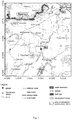
- fig. 1 a map of the area, in which the method according to the invention was carried out, is presented.
- the flow gauging station belonging to the National Hydrological and Meteorological Services (PSHM) led by the Institute of Meteorology and Water Management - National Research Institute (IMGW-PIB), is a water gauge with the code 151150110 located on the Kwisa river (watercourse according to the invention) in Gryflutter ⁇ l ski and it is the first measurement point near the outfall to the reservoir (upstream of the watercourse from the inflow to the water reservoir) indicated in fig. 1 as W1.
- Water levels H expressed in cm
- the discharges Q expressed in m 3 /s
- the considered outlet is located about 1.9 km from the outfall of the Kwisa river to Z otnickie lake, which, with no tributaries on this section, allows assuming that these discharges, when integrated over time, approximate the inflow to the reservoir.
- the second measurement point is a water gauge located on the Kwisa river in Mirsk, indicated in fig. 1 as W2.
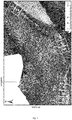
- Reliability of measurements on the W1 water gauge is verified on the basis of independent measurements of water surface area on the river (area of observations (measurements) made with the unmanned aerial vehicle is indicated by a dashed line in fig. 1 and is indicated with A, where A is expressed in m 2 ) carried out on the basis of the orthophotomap prepared from aerial images taken with a camera mounted on the unmanned aerial vehicle.
- the time of last measurement (t 0 ) was assumed to be 10:00 UTC dated 29/06/2017, which means that the expected inflow to the water reservoir is estimated for the period of 10:00-22.00 UTC on the same day.
- the embodiment is implemented in two variants described below.
- step 1 discharges in at least two measurement points are determined periodically in time.
- step 2 measurement of watercourse surface area is made.
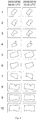
- measurements of surface area A of ten sections of the watercourse located between the water gauge in Gryf Vietnamese ⁇ l ski (W1) and the outfall of the Kwisa river to Z otnickie lake, i.e. between the measurement point near the outfall to the reservoir and the outfall to the water reservoir (indicated 1 to 10 in fig. 3 ), were made, wherein these measurements were made on the orthophotomap prepared on the basis of oblique aerial images taken with a camera mounted on the unmanned aerial vehicle.
- the measured surface areas were indicated as A 1 ,A 2 ,...,A 10 , for two consecutive instants of observation.
- Table 1 contains test values for checking whether, between two observations, there was a statistically significant increase in the water surface area which is correlated with an increase in the water level and in the discharge (Usachev, 1983; Xia et al., 1983; Smith, 1997).
- step 3 of the embodiment series of data measured in steps 1 and 2 are taken to the processing system.
- the processing system in case of the embodiment, is the HydroProg computer processing system (Niedzielski et al., 2014; fig. 2 ), especially A and B1 modules of this system.
- step 4 of the embodiment of the method according to the invention verification and/or cross compliance of times of series of collected measurement data are carried out in the HydroProg system, where the data were further processed in B1 module (Niedzielski et al., 2014; fig. 2 ), which ensured verification of cross compliance of measurement time and also compliance with UTC time.
- step 5 of the embodiment of the method according to the invention in the HydroProg system, (initial) identification and possible correction of erroneous measurement data are carried out.
- B2 module of the HydroProg system (Niedzielski et al., 2014; fig. 2 ) identifies the measurement data which deviate from the normal distribution of measurement data in the series of hydrometric measurements, and in the case of a deviating data - it creates a new, corrected series of data. This procedure is run by flagging the measurements, flowing down every hour, of the Kwisa river discharge in Gryf Vietnamese ⁇ l ski (W1 measurement point).
- a measurement point is considered erroneous (initially) only if the measurement of the Kwisa river discharge in Gryflutter ⁇ l ski is classified as deviating from the normal distribution and simultaneously the measurement of the Kwisa river discharge in Mirsk is not classified as a value deviating from the normal distribution.
- B2 module may consider the last measurement in the series as erroneous in a manner inconsistent with the actual state. An additional and independent verification of the reliability of especially the last measurement points is necessary.
- step 6 of the embodiment of the method according to the invention verification of reliability of discharge measurements from the measurement point (W1) was carried out based on data from step 2 of the embodiment of the method according to the invention (described below).
- a measurement considered (initially) to be correct in step 5 at the end of the measurement series at instant t 0 (29/06/2017, 10:00 UTC) is transmitted from step 5 to step 6.
- step 2 from data of Table 1, it follows that between the times t -1 and t 0 , there were not any statistically significant increases in the water surface area between the water gauge W1 and the outfall to the reservoir. Therefore, the analysis from Table 1 confirms correctness of the last measurement point for the discharge at instant t 0 .
- step 7 of the first variant of the embodiment a complete measurement series, comprising last measurement at t 0 , for determining the expected course of discharge variability of the Kwisa river in Gryflutter ⁇ l ski, which is necessary to calculate the expected inflow to Z otnickie lake for 12 hours ahead.
- the expected course of discharge variability of the Kwisa river in Gryf Vietnamese ⁇ l ski is generated with the use of B3, B4, C1, C2 and E modules of the HydroProg system (Niedzielski et al., 2014; fig. 2 ).
- C1, C2 and E modules a combination of univariate autoregression method and multivariate autoregression method is used (Niedzielski and Mizi ⁇ ski, 2016).
- the expected course of discharge variability of the Kwisa river in Gryf Vietnamese ⁇ l ski is a convex combination of expected course of discharge variability at this station determined by univariate and multivariate autoregression methods.
- the autoregression is based only on measurements of discharge Q on the Kwisa river in Gryfów ⁇ l ski (W1).
- the bivariate autoregression model is used which is based on measurements of discharge Q on the Kwisa river both in Gryfów ⁇ l ski (W1) and at the station located upstream in Mirsk (W2).
- This method is one of many known methods for determining the expected course of discharge variability.
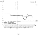
- Fig. 5 shows the actual course of the discharge hydrograph together with the course expected for 12 h ahead from instant t 0 to instants t 1 ,t 2 ,...,t 12 (since 11:00 to 22:00 UTC).
- the expected inflow to Z otnickie lake is the integral under the graph of the expected course of the discharge hydrograph in the range of t 0 to t 12 .
- the actual inflow to the water reservoir is calculated, wherein the integral under the graph of the actual course of the discharge hydrograph in the same range is considered.
- a trapezoid method was used which consists in approximating the field with trapezoids under the graph of the discharge hydrograph course and in multiplying them by 3600 (number of seconds included in one hour).
- the error value when determining the expected inflow to Z otnickie lake was small, and the reliability of this determination was high due to the confirmation by an independent measurement for the last measurement point at instant t 0 with the use of independent measurements on the orthophotomap prepared based on aerial images taken with the use of an unmanned aerial vehicle.
- step 8 the calculated expected inflow is transmitted by any means of data communications to the rule controlling the water reservoir.
- this suggests the possibility of erroneous observation at the end of the measurement series at instant t 0 .
- the second variant of the embodiment assumes an artificial modification of the last discharge measurement at instant t 0 from 1.45 m 3 /s (from the first variant of the embodiment) to 2.5 m 3 /s ( fig. 6 ).
- Value 2.5 m 3 /s was selected so as to be located in a different zone of characteristics discharges than value 1.45 m 3 /s.
- the lower limit of NSQ average discharges is in fact at about 2.4 m 3 /s, which is shown in fig. 6 .
- Situation of a rapid increase in the discharge in the period of one hour in mountain conditions may occur both at the beginning of a developing high flow and for technical reasons associated with the sensor failure or interference of third parties in the operation of the sensor. Therefore, the adopted value has grounds of the real hydrological situation.
- the expected inflow to Z otnickie lake in the time horizon of 12 hours, since 10:00 to 22:00 UTC, is calculated analogously to that described in the first variant of the embodiment.
- the percentage error of the expected 12-hour inflow to Z otnickie lake was reduced from 60.9% to 0.7%.
- the inflow value transmitted in step 8 to the rule controlling the water reservoir was reliable and potentially did not generate any expensive procedure, e.g. emergency drainage of water from the reservoir.
Landscapes
- Environmental & Geological Engineering (AREA)
- Engineering & Computer Science (AREA)
- Life Sciences & Earth Sciences (AREA)
- Atmospheric Sciences (AREA)
- Biodiversity & Conservation Biology (AREA)
- Ecology (AREA)
- Environmental Sciences (AREA)
- Measuring Volume Flow (AREA)
Priority Applications (2)
| Application Number | Priority Date | Filing Date | Title |
|---|---|---|---|
| PL16460089T PL3324219T3 (pl) | 2016-11-22 | 2016-11-22 | Sposób określania przewidywanego dopływu do zbiornika wodnego |
| EP16460089.2A EP3324219B1 (fr) | 2016-11-22 | 2016-11-22 | Procédé de détermination de captage attendu dans un réservoir d'eau |
Applications Claiming Priority (1)
| Application Number | Priority Date | Filing Date | Title |
|---|---|---|---|
| EP16460089.2A EP3324219B1 (fr) | 2016-11-22 | 2016-11-22 | Procédé de détermination de captage attendu dans un réservoir d'eau |
Publications (2)
| Publication Number | Publication Date |
|---|---|
| EP3324219A1 true EP3324219A1 (fr) | 2018-05-23 |
| EP3324219B1 EP3324219B1 (fr) | 2018-12-19 |
Family
ID=57794105
Family Applications (1)
| Application Number | Title | Priority Date | Filing Date |
|---|---|---|---|
| EP16460089.2A Active EP3324219B1 (fr) | 2016-11-22 | 2016-11-22 | Procédé de détermination de captage attendu dans un réservoir d'eau |
Country Status (2)
| Country | Link |
|---|---|
| EP (1) | EP3324219B1 (fr) |
| PL (1) | PL3324219T3 (fr) |
Cited By (4)
| Publication number | Priority date | Publication date | Assignee | Title |
|---|---|---|---|---|
| CN109558626A (zh) * | 2018-10-12 | 2019-04-02 | 华北电力大学 | 基于时变设计洪水的梯级水库汛期运行水位动态控制方法 |
| CN111983609A (zh) * | 2020-07-30 | 2020-11-24 | 中国科学院空天信息创新研究院 | 基于雷达遥感影像的湿芦苇提取方法 |
| CN114444333A (zh) * | 2022-04-07 | 2022-05-06 | 长江水利委员会长江科学院 | 生态水位分析方法、装置、电子设备及存储介质 |
| CN118798489A (zh) * | 2024-09-11 | 2024-10-18 | 大连理工大学 | 一种基于库容替代作用的水库群汛期起调水位控制域上限的推求方法 |
Citations (10)
| Publication number | Priority date | Publication date | Assignee | Title |
|---|---|---|---|---|
| JPH01191210A (ja) * | 1988-01-27 | 1989-08-01 | Hitachi Ltd | ダム・ゲート制御方式 |
| EP0839231B1 (fr) | 1995-07-17 | 2003-05-21 | Jean-Paul Sovran | Batardeau de rivage |
| US6581009B1 (en) | 2002-01-02 | 2003-06-17 | User-Centric Enterprises, Inc. | Quantitative precipitation prediction method |
| US6947842B2 (en) | 2003-01-06 | 2005-09-20 | User-Centric Enterprises, Inc. | Normalized and animated inundation maps |
| EP1456533B1 (fr) | 2001-12-20 | 2009-10-07 | Andritz Hydro GmbH | Procede et dispositif de regulation du niveau d'un barrage |
| WO2011071397A1 (fr) | 2009-12-07 | 2011-06-16 | Andrzej Rychert | Système de production de courant et de protection contre les inondations |
| US7984052B2 (en) | 2007-06-12 | 2011-07-19 | Raytheon Company | System and method for integration of data records having differing data types to a geographical information system |
| PL396077A1 (pl) | 2011-08-24 | 2013-03-04 | Marek Kalinowski | Sposób zabezpieczenia brzegu rzeki |
| US20130212048A1 (en) * | 2012-02-15 | 2013-08-15 | Ho-Cheng Lien | METHOD OF performing REAL-TIME CORRECTION OF A WATER STAGE FORECAST |
| US8614631B2 (en) | 2011-04-18 | 2013-12-24 | International Business Machines Corporation | Flood data collection and warning mechanism |
-
2016
- 2016-11-22 PL PL16460089T patent/PL3324219T3/pl unknown
- 2016-11-22 EP EP16460089.2A patent/EP3324219B1/fr active Active
Patent Citations (10)
| Publication number | Priority date | Publication date | Assignee | Title |
|---|---|---|---|---|
| JPH01191210A (ja) * | 1988-01-27 | 1989-08-01 | Hitachi Ltd | ダム・ゲート制御方式 |
| EP0839231B1 (fr) | 1995-07-17 | 2003-05-21 | Jean-Paul Sovran | Batardeau de rivage |
| EP1456533B1 (fr) | 2001-12-20 | 2009-10-07 | Andritz Hydro GmbH | Procede et dispositif de regulation du niveau d'un barrage |
| US6581009B1 (en) | 2002-01-02 | 2003-06-17 | User-Centric Enterprises, Inc. | Quantitative precipitation prediction method |
| US6947842B2 (en) | 2003-01-06 | 2005-09-20 | User-Centric Enterprises, Inc. | Normalized and animated inundation maps |
| US7984052B2 (en) | 2007-06-12 | 2011-07-19 | Raytheon Company | System and method for integration of data records having differing data types to a geographical information system |
| WO2011071397A1 (fr) | 2009-12-07 | 2011-06-16 | Andrzej Rychert | Système de production de courant et de protection contre les inondations |
| US8614631B2 (en) | 2011-04-18 | 2013-12-24 | International Business Machines Corporation | Flood data collection and warning mechanism |
| PL396077A1 (pl) | 2011-08-24 | 2013-03-04 | Marek Kalinowski | Sposób zabezpieczenia brzegu rzeki |
| US20130212048A1 (en) * | 2012-02-15 | 2013-08-15 | Ho-Cheng Lien | METHOD OF performing REAL-TIME CORRECTION OF A WATER STAGE FORECAST |
Non-Patent Citations (13)
| Title |
|---|
| BRACA G.: "Stage-discharge relationships in open channels: Practices and problems", FORALPS TECHNICAL REPORT, 2008, pages 24 |
| EFRON, B.: "Annals of Statistics", vol. 7, 1979, article "Bootstrap Methods: Another Look at the Jackknife", pages: 1 - 26 |
| GHOSH S.N.; DESAI V.R.: "Environmental Hydrology and Hydraulics Eco-technological Practices for Sustainable Development", 2006, TAYLOR & FRANCIS |
| NIEDZIELSKI T.; MIZINSKI B.: "Real-time hydrograph modelling in the upper Nysa Klodzka river basin (SW Poland): a two-model hydrologic ensemble prediction approach", STOCHASTIC ENVIRONMENTAL RESEARCH AND RISK ASSESSMENT, 2016 |
| NIEDZIELSKI T.; MIZINSKI B.; KRYZA M.; NETZEL P.; WIECZOREK M.; KASPRZAK M.; KOSEK W.; MIGON P.; SZYMANOWSKI M.; JEZIORSKA J.: "HydroProg: a system for hydrologic forecasting in real time based on the multimodelling approach", METEOROLOGY HYDROLOGY AND WATER MANAGEMENT. RESEARCH AND OPERATIONAL APPLICATIONS, vol. 2, 2014, pages 65 - 72 |
| NIEDZIELSKI T.; WITEK M.; SPALLEK W.: "Observing river stages using unmanned aerial vehicles", HYDROLOGY AND EARTH SYSTEM SCIENCES, vol. 20, 2016, pages 3193 - 3205, XP055362246, DOI: doi:10.5194/hess-20-3193-2016 |
| NIEDZIELSKI T.; WITEK M.; SPALLEK W.: "Observing river stages using unmanned aerial vehicles", HYDROLOGY AND EARTH SYSTEM SCIENCES, vol. 20, 9 August 2016 (2016-08-09), pages 3193 - 3205, XP002768990 * |
| ROSNER B.: "Percentage points for a generalized ESD many-outlier procedure", TECHNOMETRICS, vol. 25, 1983, pages 165 - 172 |
| SMITH L.C.: "Satellite remote sensing of river inundation area, stage, and discharge: a review", HYDROLOGICAL PROCESSES, vol. 11, 1997, pages 1427 - 1439 |
| TURNIPSEED D.P.; SAUER V.B.: "Discharge measurements at gaging stations: U.S. Geological Survey Techniques and Methods book 3", 2010, article "chap. A8", pages: 87 |
| USACHEV V.F.: "Proceedings of the Hamburg Symposium, IAHS Publ. 145", 1983, article "Evaluation of flood plain inundations by remote sensing methods", pages: 475 - 482 |
| WESTOBY M.J.; BRASINGTON J.; GLASSER N.F.; HAMBREY M.J.; REYNOLDS J.M.: "Structure-from-Motion' photogrammetry: A low-cost, effective tool for geoscience applications", GEOMORPHOLOGY, vol. 179, 2012, pages 300 - 314, XP055398584, DOI: doi:10.1016/j.geomorph.2012.08.021 |
| XIA L.; SHULIN Z.; XIANGLIAN L.: "Proceedings of the Hamburg Symposium, IAHS Publ. 145.", 1983, article "The application of Landsat imagery in the surveying of water resources of Dongting Lake", pages: 483 - 489 |
Cited By (6)
| Publication number | Priority date | Publication date | Assignee | Title |
|---|---|---|---|---|
| CN109558626A (zh) * | 2018-10-12 | 2019-04-02 | 华北电力大学 | 基于时变设计洪水的梯级水库汛期运行水位动态控制方法 |
| CN109558626B (zh) * | 2018-10-12 | 2023-04-25 | 华北电力大学 | 基于时变设计洪水的梯级水库汛期运行水位动态控制方法 |
| CN111983609A (zh) * | 2020-07-30 | 2020-11-24 | 中国科学院空天信息创新研究院 | 基于雷达遥感影像的湿芦苇提取方法 |
| CN111983609B (zh) * | 2020-07-30 | 2022-02-08 | 中国科学院空天信息创新研究院 | 基于雷达遥感影像的湿芦苇提取方法 |
| CN114444333A (zh) * | 2022-04-07 | 2022-05-06 | 长江水利委员会长江科学院 | 生态水位分析方法、装置、电子设备及存储介质 |
| CN118798489A (zh) * | 2024-09-11 | 2024-10-18 | 大连理工大学 | 一种基于库容替代作用的水库群汛期起调水位控制域上限的推求方法 |
Also Published As
| Publication number | Publication date |
|---|---|
| PL3324219T3 (pl) | 2019-06-28 |
| EP3324219B1 (fr) | 2018-12-19 |
Similar Documents
| Publication | Publication Date | Title |
|---|---|---|
| US12585971B2 (en) | Systems and methods for automatic environmental planning and decision support using artificial intelligence and data fusion techniques on distributed sensor network data | |
| US11237148B2 (en) | Flood disaster prediction | |
| Bajracharya et al. | Inventory of glacial lakes and identification of potentially dangerous glacial lakes in the Koshi, Gandaki, and Karnali river basins of Nepal, the Tibet Autonomous Region of China, and India | |
| Patro et al. | Hydrodynamic modelling of a large flood‐prone river system in India with limited data | |
| Triet et al. | Has dyke development in the Vietnamese Mekong Delta shifted flood hazard downstream? | |
| Huggel et al. | Regional-scale GIS-models for assessment of hazards from glacier lake outbursts: evaluation and application in the Swiss Alps | |
| Elshorbagy et al. | Topography-and nightlight-based national flood risk assessment in Canada | |
| EP3324219B1 (fr) | Procédé de détermination de captage attendu dans un réservoir d'eau | |
| Al Saud | Flood control management for the city and surroundings of Jeddah, Saudi Arabia | |
| Poppenga et al. | Hydrologic connectivity: Quantitative assessments of hydrologic-enforced drainage structures in an elevation model | |
| Pagano | Evaluation of Mekong River commission operational flood forecasts, 2000–2012 | |
| Lincoln et al. | A Preliminary Look at Using Rainfall Average Recurrence Interval to Characterize Flash Flood Events for Real-time Warning Forecasting. | |
| Manzoor et al. | Probabilistic flood risk assessment using coupled hydrologic and 2D-hydraulic model in the Jhelum River, Northwest Himalayas | |
| Morsy et al. | Impact of geospatial data enhancements for regional-scale 2D hydrodynamic flood modeling: Case study for the coastal plain of Virginia | |
| Lorini et al. | Venice was flooding... one tweet at a time | |
| Sudalaimuthu et al. | Development of digital elevation model for assessment of flood vulnerable areas using Cartosat‐1 and GIS at Thamirabarani river, Tamilnadu, India | |
| Reinwarth et al. | Estimating the sediment trap efficiency of intermittently dry reservoirs: lessons from the Kruger National Park, South Africa | |
| Penton et al. | Spatial modelling of floodplain inundation combining satellite imagery and elevation models | |
| Farina et al. | Development of an early warning system for shallow landslide hazard in the Grasberg area, Indonesia | |
| Manyifika et al. | Diagnostic assessment on urban floods using satellite data and hydrologic models in Kigali, Rwanda | |
| Yoon et al. | Application of an X-Band multiparameter radar network for rain-based urban flood forecasting | |
| Poppenga et al. | Hydrologic enforcement of lidar DEMs | |
| Awange et al. | Disaster monitoring and management | |
| Adhikari et al. | Community based flash flood early warning system: a low-cost technology for Nepalese mountains | |
| Coughenour et al. | In the shadow of the dam–Hydrology of the Little Conemaugh river and its South Fork, with insights about past and future flooding |
Legal Events
| Date | Code | Title | Description |
|---|---|---|---|
| STAA | Information on the status of an ep patent application or granted ep patent |
Free format text: STATUS: EXAMINATION IS IN PROGRESS |
|
| PUAI | Public reference made under article 153(3) epc to a published international application that has entered the european phase |
Free format text: ORIGINAL CODE: 0009012 |
|
| 17P | Request for examination filed |
Effective date: 20161125 |
|
| AK | Designated contracting states |
Kind code of ref document: A1 Designated state(s): AL AT BE BG CH CY CZ DE DK EE ES FI FR GB GR HR HU IE IS IT LI LT LU LV MC MK MT NL NO PL PT RO RS SE SI SK SM TR |
|
| AX | Request for extension of the european patent |
Extension state: BA ME |
|
| GRAP | Despatch of communication of intention to grant a patent |
Free format text: ORIGINAL CODE: EPIDOSNIGR1 |
|
| STAA | Information on the status of an ep patent application or granted ep patent |
Free format text: STATUS: GRANT OF PATENT IS INTENDED |
|
| INTG | Intention to grant announced |
Effective date: 20180619 |
|
| GRAS | Grant fee paid |
Free format text: ORIGINAL CODE: EPIDOSNIGR3 |
|
| GRAA | (expected) grant |
Free format text: ORIGINAL CODE: 0009210 |
|
| STAA | Information on the status of an ep patent application or granted ep patent |
Free format text: STATUS: THE PATENT HAS BEEN GRANTED |
|
| RIN1 | Information on inventor provided before grant (corrected) |
Inventor name: SWIERCZYNSKA-CHLASCIAK, MALGORZATA Inventor name: MIZINSKI, BARTLOMIEJ Inventor name: NIEDZIELSKI, TOMASZ Inventor name: KRYZA, MACIEJ |
|
| AK | Designated contracting states |
Kind code of ref document: B1 Designated state(s): AL AT BE BG CH CY CZ DE DK EE ES FI FR GB GR HR HU IE IS IT LI LT LU LV MC MK MT NL NO PL PT RO RS SE SI SK SM TR |
|
| REG | Reference to a national code |
Ref country code: GB Ref legal event code: FG4D |
|
| REG | Reference to a national code |
Ref country code: CH Ref legal event code: EP |
|
| REG | Reference to a national code |
Ref country code: IE Ref legal event code: FG4D |
|
| REG | Reference to a national code |
Ref country code: DE Ref legal event code: R096 Ref document number: 602016008426 Country of ref document: DE |
|
| REG | Reference to a national code |
Ref country code: AT Ref legal event code: REF Ref document number: 1079307 Country of ref document: AT Kind code of ref document: T Effective date: 20190115 |
|
| REG | Reference to a national code |
Ref country code: NL Ref legal event code: MP Effective date: 20181219 |
|
| PG25 | Lapsed in a contracting state [announced via postgrant information from national office to epo] |
Ref country code: LT Free format text: LAPSE BECAUSE OF FAILURE TO SUBMIT A TRANSLATION OF THE DESCRIPTION OR TO PAY THE FEE WITHIN THE PRESCRIBED TIME-LIMIT Effective date: 20181219 Ref country code: HR Free format text: LAPSE BECAUSE OF FAILURE TO SUBMIT A TRANSLATION OF THE DESCRIPTION OR TO PAY THE FEE WITHIN THE PRESCRIBED TIME-LIMIT Effective date: 20181219 Ref country code: BG Free format text: LAPSE BECAUSE OF FAILURE TO SUBMIT A TRANSLATION OF THE DESCRIPTION OR TO PAY THE FEE WITHIN THE PRESCRIBED TIME-LIMIT Effective date: 20190319 Ref country code: NO Free format text: LAPSE BECAUSE OF FAILURE TO SUBMIT A TRANSLATION OF THE DESCRIPTION OR TO PAY THE FEE WITHIN THE PRESCRIBED TIME-LIMIT Effective date: 20190319 Ref country code: FI Free format text: LAPSE BECAUSE OF FAILURE TO SUBMIT A TRANSLATION OF THE DESCRIPTION OR TO PAY THE FEE WITHIN THE PRESCRIBED TIME-LIMIT Effective date: 20181219 Ref country code: LV Free format text: LAPSE BECAUSE OF FAILURE TO SUBMIT A TRANSLATION OF THE DESCRIPTION OR TO PAY THE FEE WITHIN THE PRESCRIBED TIME-LIMIT Effective date: 20181219 |
|
| REG | Reference to a national code |
Ref country code: LT Ref legal event code: MG4D |
|
| REG | Reference to a national code |
Ref country code: AT Ref legal event code: MK05 Ref document number: 1079307 Country of ref document: AT Kind code of ref document: T Effective date: 20181219 |
|
| PG25 | Lapsed in a contracting state [announced via postgrant information from national office to epo] |
Ref country code: GR Free format text: LAPSE BECAUSE OF FAILURE TO SUBMIT A TRANSLATION OF THE DESCRIPTION OR TO PAY THE FEE WITHIN THE PRESCRIBED TIME-LIMIT Effective date: 20190320 Ref country code: AL Free format text: LAPSE BECAUSE OF FAILURE TO SUBMIT A TRANSLATION OF THE DESCRIPTION OR TO PAY THE FEE WITHIN THE PRESCRIBED TIME-LIMIT Effective date: 20181219 Ref country code: SE Free format text: LAPSE BECAUSE OF FAILURE TO SUBMIT A TRANSLATION OF THE DESCRIPTION OR TO PAY THE FEE WITHIN THE PRESCRIBED TIME-LIMIT Effective date: 20181219 Ref country code: RS Free format text: LAPSE BECAUSE OF FAILURE TO SUBMIT A TRANSLATION OF THE DESCRIPTION OR TO PAY THE FEE WITHIN THE PRESCRIBED TIME-LIMIT Effective date: 20181219 |
|
| PG25 | Lapsed in a contracting state [announced via postgrant information from national office to epo] |
Ref country code: NL Free format text: LAPSE BECAUSE OF FAILURE TO SUBMIT A TRANSLATION OF THE DESCRIPTION OR TO PAY THE FEE WITHIN THE PRESCRIBED TIME-LIMIT Effective date: 20181219 |
|
| PG25 | Lapsed in a contracting state [announced via postgrant information from national office to epo] |
Ref country code: ES Free format text: LAPSE BECAUSE OF FAILURE TO SUBMIT A TRANSLATION OF THE DESCRIPTION OR TO PAY THE FEE WITHIN THE PRESCRIBED TIME-LIMIT Effective date: 20181219 Ref country code: IT Free format text: LAPSE BECAUSE OF FAILURE TO SUBMIT A TRANSLATION OF THE DESCRIPTION OR TO PAY THE FEE WITHIN THE PRESCRIBED TIME-LIMIT Effective date: 20181219 Ref country code: CZ Free format text: LAPSE BECAUSE OF FAILURE TO SUBMIT A TRANSLATION OF THE DESCRIPTION OR TO PAY THE FEE WITHIN THE PRESCRIBED TIME-LIMIT Effective date: 20181219 Ref country code: PT Free format text: LAPSE BECAUSE OF FAILURE TO SUBMIT A TRANSLATION OF THE DESCRIPTION OR TO PAY THE FEE WITHIN THE PRESCRIBED TIME-LIMIT Effective date: 20190419 |
|
| PG25 | Lapsed in a contracting state [announced via postgrant information from national office to epo] |
Ref country code: RO Free format text: LAPSE BECAUSE OF FAILURE TO SUBMIT A TRANSLATION OF THE DESCRIPTION OR TO PAY THE FEE WITHIN THE PRESCRIBED TIME-LIMIT Effective date: 20181219 Ref country code: IS Free format text: LAPSE BECAUSE OF FAILURE TO SUBMIT A TRANSLATION OF THE DESCRIPTION OR TO PAY THE FEE WITHIN THE PRESCRIBED TIME-LIMIT Effective date: 20190419 Ref country code: EE Free format text: LAPSE BECAUSE OF FAILURE TO SUBMIT A TRANSLATION OF THE DESCRIPTION OR TO PAY THE FEE WITHIN THE PRESCRIBED TIME-LIMIT Effective date: 20181219 Ref country code: SM Free format text: LAPSE BECAUSE OF FAILURE TO SUBMIT A TRANSLATION OF THE DESCRIPTION OR TO PAY THE FEE WITHIN THE PRESCRIBED TIME-LIMIT Effective date: 20181219 Ref country code: SK Free format text: LAPSE BECAUSE OF FAILURE TO SUBMIT A TRANSLATION OF THE DESCRIPTION OR TO PAY THE FEE WITHIN THE PRESCRIBED TIME-LIMIT Effective date: 20181219 |
|
| REG | Reference to a national code |
Ref country code: DE Ref legal event code: R097 Ref document number: 602016008426 Country of ref document: DE |
|
| PLBE | No opposition filed within time limit |
Free format text: ORIGINAL CODE: 0009261 |
|
| STAA | Information on the status of an ep patent application or granted ep patent |
Free format text: STATUS: NO OPPOSITION FILED WITHIN TIME LIMIT |
|
| PG25 | Lapsed in a contracting state [announced via postgrant information from national office to epo] |
Ref country code: AT Free format text: LAPSE BECAUSE OF FAILURE TO SUBMIT A TRANSLATION OF THE DESCRIPTION OR TO PAY THE FEE WITHIN THE PRESCRIBED TIME-LIMIT Effective date: 20181219 Ref country code: DK Free format text: LAPSE BECAUSE OF FAILURE TO SUBMIT A TRANSLATION OF THE DESCRIPTION OR TO PAY THE FEE WITHIN THE PRESCRIBED TIME-LIMIT Effective date: 20181219 |
|
| 26N | No opposition filed |
Effective date: 20190920 |
|
| PG25 | Lapsed in a contracting state [announced via postgrant information from national office to epo] |
Ref country code: TR Free format text: LAPSE BECAUSE OF FAILURE TO SUBMIT A TRANSLATION OF THE DESCRIPTION OR TO PAY THE FEE WITHIN THE PRESCRIBED TIME-LIMIT Effective date: 20181219 |
|
| REG | Reference to a national code |
Ref country code: CH Ref legal event code: PL |
|
| PG25 | Lapsed in a contracting state [announced via postgrant information from national office to epo] |
Ref country code: CH Free format text: LAPSE BECAUSE OF NON-PAYMENT OF DUE FEES Effective date: 20191130 Ref country code: LI Free format text: LAPSE BECAUSE OF NON-PAYMENT OF DUE FEES Effective date: 20191130 Ref country code: LU Free format text: LAPSE BECAUSE OF NON-PAYMENT OF DUE FEES Effective date: 20191122 Ref country code: MC Free format text: LAPSE BECAUSE OF FAILURE TO SUBMIT A TRANSLATION OF THE DESCRIPTION OR TO PAY THE FEE WITHIN THE PRESCRIBED TIME-LIMIT Effective date: 20181219 |
|
| REG | Reference to a national code |
Ref country code: BE Ref legal event code: MM Effective date: 20191130 |
|
| PG25 | Lapsed in a contracting state [announced via postgrant information from national office to epo] |
Ref country code: IE Free format text: LAPSE BECAUSE OF NON-PAYMENT OF DUE FEES Effective date: 20191122 |
|
| PG25 | Lapsed in a contracting state [announced via postgrant information from national office to epo] |
Ref country code: BE Free format text: LAPSE BECAUSE OF NON-PAYMENT OF DUE FEES Effective date: 20191130 |
|
| PG25 | Lapsed in a contracting state [announced via postgrant information from national office to epo] |
Ref country code: CY Free format text: LAPSE BECAUSE OF FAILURE TO SUBMIT A TRANSLATION OF THE DESCRIPTION OR TO PAY THE FEE WITHIN THE PRESCRIBED TIME-LIMIT Effective date: 20181219 |
|
| PG25 | Lapsed in a contracting state [announced via postgrant information from national office to epo] |
Ref country code: HU Free format text: LAPSE BECAUSE OF FAILURE TO SUBMIT A TRANSLATION OF THE DESCRIPTION OR TO PAY THE FEE WITHIN THE PRESCRIBED TIME-LIMIT; INVALID AB INITIO Effective date: 20161122 Ref country code: MT Free format text: LAPSE BECAUSE OF FAILURE TO SUBMIT A TRANSLATION OF THE DESCRIPTION OR TO PAY THE FEE WITHIN THE PRESCRIBED TIME-LIMIT Effective date: 20181219 |
|
| PG25 | Lapsed in a contracting state [announced via postgrant information from national office to epo] |
Ref country code: SI Free format text: LAPSE BECAUSE OF FAILURE TO SUBMIT A TRANSLATION OF THE DESCRIPTION OR TO PAY THE FEE WITHIN THE PRESCRIBED TIME-LIMIT Effective date: 20181219 |
|
| PGFP | Annual fee paid to national office [announced via postgrant information from national office to epo] |
Ref country code: GB Payment date: 20211118 Year of fee payment: 6 Ref country code: FR Payment date: 20211102 Year of fee payment: 6 |
|
| PG25 | Lapsed in a contracting state [announced via postgrant information from national office to epo] |
Ref country code: MK Free format text: LAPSE BECAUSE OF FAILURE TO SUBMIT A TRANSLATION OF THE DESCRIPTION OR TO PAY THE FEE WITHIN THE PRESCRIBED TIME-LIMIT Effective date: 20181219 |
|
| P01 | Opt-out of the competence of the unified patent court (upc) registered |
Effective date: 20230411 |
|
| GBPC | Gb: european patent ceased through non-payment of renewal fee |
Effective date: 20221122 |
|
| PG25 | Lapsed in a contracting state [announced via postgrant information from national office to epo] |
Ref country code: GB Free format text: LAPSE BECAUSE OF NON-PAYMENT OF DUE FEES Effective date: 20221122 |
|
| PG25 | Lapsed in a contracting state [announced via postgrant information from national office to epo] |
Ref country code: FR Free format text: LAPSE BECAUSE OF NON-PAYMENT OF DUE FEES Effective date: 20221130 |
|
| PGFP | Annual fee paid to national office [announced via postgrant information from national office to epo] |
Ref country code: DE Payment date: 20251126 Year of fee payment: 10 |
|
| PGFP | Annual fee paid to national office [announced via postgrant information from national office to epo] |
Ref country code: PL Payment date: 20260115 Year of fee payment: 10 |