EP3324254A1 - Dispositif et procédé de détermination des paramètres d'un dispositif de réglage - Google Patents
Dispositif et procédé de détermination des paramètres d'un dispositif de réglage Download PDFInfo
- Publication number
- EP3324254A1 EP3324254A1 EP16199391.0A EP16199391A EP3324254A1 EP 3324254 A1 EP3324254 A1 EP 3324254A1 EP 16199391 A EP16199391 A EP 16199391A EP 3324254 A1 EP3324254 A1 EP 3324254A1
- Authority
- EP
- European Patent Office
- Prior art keywords
- model
- controller
- controlled system
- control
- parameters
- Prior art date
- Legal status (The legal status is an assumption and is not a legal conclusion. Google has not performed a legal analysis and makes no representation as to the accuracy of the status listed.)
- Withdrawn
Links
- 238000000034 method Methods 0.000 title claims abstract description 65
- 238000004088 simulation Methods 0.000 claims abstract description 43
- 238000005457 optimization Methods 0.000 claims abstract description 20
- 238000013461 design Methods 0.000 claims abstract description 19
- 238000004590 computer program Methods 0.000 claims description 12
- 238000005070 sampling Methods 0.000 claims description 6
- 238000011045 prefiltration Methods 0.000 claims description 4
- 230000001105 regulatory effect Effects 0.000 claims description 4
- 230000008569 process Effects 0.000 abstract description 31
- 230000008901 benefit Effects 0.000 abstract description 8
- 230000006399 behavior Effects 0.000 description 45
- 230000008859 change Effects 0.000 description 9
- 230000005284 excitation Effects 0.000 description 8
- XLYOFNOQVPJJNP-UHFFFAOYSA-N water Substances O XLYOFNOQVPJJNP-UHFFFAOYSA-N 0.000 description 8
- 230000006870 function Effects 0.000 description 6
- 230000004044 response Effects 0.000 description 6
- 238000012546 transfer Methods 0.000 description 6
- 238000013016 damping Methods 0.000 description 5
- 230000000694 effects Effects 0.000 description 5
- 238000004364 calculation method Methods 0.000 description 3
- 238000010438 heat treatment Methods 0.000 description 3
- 238000004422 calculation algorithm Methods 0.000 description 2
- 230000004069 differentiation Effects 0.000 description 2
- 238000011156 evaluation Methods 0.000 description 2
- 238000012544 monitoring process Methods 0.000 description 2
- 238000004886 process control Methods 0.000 description 2
- 230000002787 reinforcement Effects 0.000 description 2
- 230000006978 adaptation Effects 0.000 description 1
- 230000003321 amplification Effects 0.000 description 1
- 230000033228 biological regulation Effects 0.000 description 1
- 239000003795 chemical substances by application Substances 0.000 description 1
- 238000007405 data analysis Methods 0.000 description 1
- 238000012517 data analytics Methods 0.000 description 1
- 230000001419 dependent effect Effects 0.000 description 1
- 238000011161 development Methods 0.000 description 1
- 230000018109 developmental process Effects 0.000 description 1
- 238000010586 diagram Methods 0.000 description 1
- 238000003384 imaging method Methods 0.000 description 1
- 238000013507 mapping Methods 0.000 description 1
- 238000005259 measurement Methods 0.000 description 1
- 238000010327 methods by industry Methods 0.000 description 1
- 238000003199 nucleic acid amplification method Methods 0.000 description 1
- 230000003534 oscillatory effect Effects 0.000 description 1
- 230000001629 suppression Effects 0.000 description 1
- 230000002123 temporal effect Effects 0.000 description 1
- 238000012360 testing method Methods 0.000 description 1
- 238000012549 training Methods 0.000 description 1
- 238000011144 upstream manufacturing Methods 0.000 description 1
- 239000013598 vector Substances 0.000 description 1
Images
Classifications
-
- G—PHYSICS
- G05—CONTROLLING; REGULATING
- G05B—CONTROL OR REGULATING SYSTEMS IN GENERAL; FUNCTIONAL ELEMENTS OF SUCH SYSTEMS; MONITORING OR TESTING ARRANGEMENTS FOR SUCH SYSTEMS OR ELEMENTS
- G05B13/00—Adaptive control systems, i.e. systems automatically adjusting themselves to have a performance which is optimum according to some preassigned criterion
- G05B13/02—Adaptive control systems, i.e. systems automatically adjusting themselves to have a performance which is optimum according to some preassigned criterion electric
- G05B13/04—Adaptive control systems, i.e. systems automatically adjusting themselves to have a performance which is optimum according to some preassigned criterion electric involving the use of models or simulators
- G05B13/042—Adaptive control systems, i.e. systems automatically adjusting themselves to have a performance which is optimum according to some preassigned criterion electric involving the use of models or simulators in which a parameter or coefficient is automatically adjusted to optimise the performance
-
- G—PHYSICS
- G05—CONTROLLING; REGULATING
- G05B—CONTROL OR REGULATING SYSTEMS IN GENERAL; FUNCTIONAL ELEMENTS OF SUCH SYSTEMS; MONITORING OR TESTING ARRANGEMENTS FOR SUCH SYSTEMS OR ELEMENTS
- G05B6/00—Internal feedback arrangements for obtaining particular characteristics, e.g. proportional, integral or differential
- G05B6/02—Internal feedback arrangements for obtaining particular characteristics, e.g. proportional, integral or differential electric
-
- G—PHYSICS
- G05—CONTROLLING; REGULATING
- G05B—CONTROL OR REGULATING SYSTEMS IN GENERAL; FUNCTIONAL ELEMENTS OF SUCH SYSTEMS; MONITORING OR TESTING ARRANGEMENTS FOR SUCH SYSTEMS OR ELEMENTS
- G05B2219/00—Program-control systems
- G05B2219/30—Nc systems
- G05B2219/42—Servomotor, servo controller kind till VSS
- G05B2219/42162—Model reference adaptive control MRAC, correction fictive-real error, position
Definitions
- the invention relates to a device and a method for determining the parameters of a control device for a controlled system, wherein the device is designed to determine based on detected input and output signals of the controlled system a simulation model for the controlled system and to identify its parameters. On the basis of a model-based design method and the previously determined simulation model, parameters of the control device for a desired behavior of the control loop are determined.
- the leadership behavior is characterized by how a controlled variable, which represents a process variable in a process or process plant, responds to a change in a desired value.
- a controlled variable which represents a process variable in a process or process plant
- responds to a change in a desired value in order to assess the guiding behavior of a control loop.
- it is excited by the application of a setpoint variable with a step-shaped course and the step response is evaluated.
- a desired settling time after which the controlled variable is supposed to have reached a defined target corridor, is preset and a maximum overshoot of the controlled variable.
- the disturbance behavior describes how the controlled variable reacts to a fault. If, for example, a jump-like fault acts on the controlled system from the outside, the controlled variable will deviate. The controller should keep this deviation low and quickly return the controlled variable to the setpoint.
- Dead times arise, for example, when an actuator, with which the process is influenced as an actuator, and a sensor with which actual values of a controlled variable are detected in the process, are placed at a certain distance from each other.
- an actuator with which the process is influenced as an actuator
- a sensor with which actual values of a controlled variable are detected in the process
- the heating of a reactor by means of an external instantaneous heater from which the heated water is pumped via a pipe into a jacket of the reactor.
- Actuator is the external instantaneous water heater.
- the measurement of the temperature as a controlled variable takes place in the reactor by means of a temperature sensor. The time that elapses until the heated water arrives in the jacket represents the dead time of the controlled system.
- Dead times usually have a negative effect on the achievable control loop performance.
- its dynamics In order to ensure a stable behavior of the closed loop even if there is a dead time, its dynamics must be significantly slowed down using a conventional controller. Attempting to accelerate leadership behavior can lead to undesirable oscillatory or even unstable behavior.
- a possibility for improving the control loop behavior could be seen in using, instead of a conventional controller, a trajectory control in which a model of the controlled system leads to desired progressions the control variable matching control variables are calculated.
- a trajectory sequence controller undertakes the task of correcting deviations between the trajectory and the real controlled variable. Since the calculations required for this can be computationally intensive, these are usually performed offline. This leads disadvantageously to the fact that only pre-calculated trajectories are available in the operation of the control loop.
- the invention has for its object to provide a device and a method for determining the parameters of a control device for a controlled system, by which the use of a model successor controller is facilitated as a control device by the determination and determination of parameters of the control device is largely automated, so that the parameterization can be carried out by an operator without special technical control knowledge.
- a simulation model for the controlled system is first determined.
- a "historical" dataset which was acquired and stored in a system in a previous operation of the controlled system, can be evaluated or a possibility can be used, a controlled system, for example, by applying a step-shaped Actively stimulate the manipulated variable profile.
- the determination of the simulation model can, for example, with the aid of the above-mentioned EP 0 520 233 A2 done known method.
- the identified simulation model can be used as a model of the controlled system in the feedforward control of the control device designed as a model follow-up control.
- the parameterization of the master controller in the feedforward control and the parameterization of the slave controller are model based. Divergent model-based design methods may be used.
- the designed as P or PD controller master controller is parameterized for a good leadership behavior, designed as a PI or PID controller slave controller for a good noise behavior.
- a suitable model-based design method a known method can be used in each case.
- the master controller can be designed by means of the magnitude optimum and the slave controller by means of symmetrical optimum, wherein the phase margin is predetermined, for example, at 30 degrees.
- Such a parameterized model sequence control generally already shows a significantly improved behavior compared to a single, classic controller.
- the master controller is arranged in the feedforward control in the feedback of the model control circuit located in the pilot control.
- setpoint changes are often made jump-shaped. This results in a jump excitation of the pilot control model loop. If this jump were applied directly to a PD controller located in the forward branch, the differentiation of the jump would lead to an output of the maximum manipulated variable value by the controller.
- the PD controller is in the feedback, this has the advantage that the step-shaped setpoint change is filtered by the simulation model of the controlled system to the PD controller. In general, therefore, can be achieved by the arrangement of the guide controller in the feedback that the manipulated variable of the model control loop less often in their manipulated variable limitation.
- the parameters of the control device previously determined by means of a model-based design method can lead to a control behavior which still has an overshoot, which may be undesirable depending on the application.
- model errors which can hardly be ruled out in practice, ensure that the leadership behavior deteriorates, since the slave controller also influences the control behavior of the control device in this case.
- an additional optimization of the parameters of the control device can be carried out, the two aspects overshoot and model uncertainty receive special importance.
- a quality criterion is selected, in which preferably both the guiding and the disturbing behavior are received.
- a suitable quality criterion is, for example, the sum of the quadratic control error and the squared control variable on the controlled system.
- a maximum value for the overshoot and a maximum value of the disturbance deflection can be included in the quality criterion.
- the identified model which is also referred to below as a nominal model, is used in the precontrol. If this were also used to simulate the process, the influence of model uncertainties would be completely lost. Therefore, a model family is created whose members differ in their dynamic behavior, such as the rise time, and / or in stationary behavior, that is, the stationary reinforcement, from the nominal model.
- Information about a suitable quantity of the deviations between the individual model variants can be obtained from historical data of process variables or, if a jump excitation was carried out for process identification, from data with several successive jump excitations.
- an optimization based on the quadratic control error may have the problem that it leads to a closed loop with poor damping and hence oscillating behavior.
- a minimum damping for the closed loop ie for the controlled by the control system, can be specified as a constraint for the optimization.
- other values of damping can be useful and specified as a constraint.
- a dead time in the controlled system can be a special challenge for a control device represent.
- the model sequence control with automatic determination of the required parameters can be used advantageously.
- the nominal model of the controlled system used in the pre-control can be decomposed to take into account the dead time in a submodel without dead time and a dead time model, which is connected downstream of the linear submodule in a series circuit.
- the output signal of the dead-time-free submodel is then fed back, while the output signal of the downstream deadtime model is passed to the following controller as setpoint specification.
- This realization time constant T R is generally chosen to be very small, for example to one fifth of the derivative time.
- the dynamics of the controlled system is usually increased by the control, so that even when using a real PD controller often very fast dynamics and thus very small time constants of the closed loop result.
- very fast dynamic effects may be barely visible in a step response and are also called non-dominant.
- the situation could occur that the fastest time constant in the feedforward control is less than twice the sampling time. Thus, the Nyquist theorem would be violated and the simulation of the master control loop could become numerically unstable.
- the determination of the parameters of a control device designed as a model sequence controller can be implemented, for example, by means of an engineering tool of a process control system or advantageously in a software environment for cloud-based system monitoring.
- a software environment represents, for example, the data-based remote service "Control Performance Analytics” from Siemens AG.
- Data from a customer system are collected with the help of software agents, aggregated and sent to a Siemens Service Operation Center where they are remotely located Service computer to be stored. There, the data is semi-automatically evaluated with the aid of various "Data Analytics" software applications. If necessary, specially trained experts can work highly efficiently on this database for the Remove Service.
- results of the data analysis and the optimization of the control can be displayed on a monitor of the remote service computer and / or provided on a Sharepoint so that they are viewed by the end user, ie the operator of the automated process plant, for example in a browser can. If a comparison of the newly parameterized control device with the system already existing in the system offers advantages for the user, this can be offered to the acquisition and use of the new control device.
- the device and the method for determining the parameters of a control device designed as a model sequence controller is thus preferably implemented in software or in a combination of software / hardware, so that the invention also includes a computer program with computer executable program code instructions for implementing the method on a suitable computing unit concerns.
- the invention also relates to a computer program product, in particular a data carrier or a storage medium, with a computer program executable by a computer.
- Such a computer program can, for example be stored in a memory of a control system of an automated process engineering plant or loaded into it, so that the operation of the system, the method for determining the parameters and, where appropriate, to optimize them automatically performed, or the computer program can in a cloud-based determination of the parameters in a memory of a remote service computer held or loadable in this.
- the computer program can also be kept in a computer connected to the control system and the remote service computer, which communicates via networks with the other two systems.
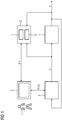
- FIG. 1 forms a controlled system 1 with a control device 2 is part of an automated process plant whose behavior is to be optimized.
- the controlled system 1 is, for example, a temperature controller for a reactor which is filled with a process medium.
- the reactor is heated by a jacket, which is connected to a separate water circuit for its heating.
- the water is heated by an electric water heater and pumped back into the jacket to heat the process medium.
- a controlled variable y the process variable "temperature in the reactor" can be measured.
- a water heater supplied to the water heater is generated as a manipulated variable u by the control device 2 for adjusting the temperature to a predetermined by a control unit 3 setpoint w.
- the structure of the control device 2 can also be selected by means of a control signal s, and the controller type determined thereby can be provided with the respectively required parameters p.
- This can be automated or corresponding to the input of an operator 4.
- a model sequence controller can be selected as controller type of the control device 2 whose parameters are automatically determined by a device 5 and offered to the operator 4 by display on the operating unit 3 for selective transfer to the control device 2.
- the device 5 for determining the parameter p of the control device 2 has a data memory 6, in which gradients of the manipulated variable u are stored as the input signal of the controlled system 1 and gradients of the controlled variable y as an output signal of the controlled system 1.
- This may, for example, be historical process data which is recorded in an earlier operation of the plant for the process variable "electrical heating power” or for the process variable "temperature in the reactor” and in each case as temporal data sequences corresponding to the measured values obtained in a measuring window, are stored.
- the data stored in the memory 6 can be curves of the input and output signals of the controlled system 2, which were obtained by active excitation of the controlled system 1, for example a jump-shaped excitation for better identification of a simulation model for the controlled system 1.
- An evaluation device 7 identifies the structure of a suitable simulation model and its parameters based on the input and output signals of the controlled system 1 stored in the data memory 6.
- the parameters p are also determined by the evaluation device 7.
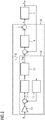
- FIG. 2 a structure of a control device 8 is shown, which is obtained when, as a controller type of the control device 2 ( FIG. 1 ) a model follower is selected.
- Controlled system 1 manipulated variable u, controlled variable y and setpoint w were already based on FIG. 1 explained.
- a feedforward control 9 of the model sequence controller a model control loop is formed with a dead-time-free submodel 10 of the controlled system 1 and a guide controller 11 arranged in the feedback loop.
- a deadtime model 12 which is connected downstream of the dead time-free sub-model 10, forms a further component of the simulation model for the dead-time controlled system 1.
- the output signal of the dead time-free submodel 10 is fed back, so that the dead time of the controlled system 1 has no effect on the in the Pilot control 9 located control loop has.
- a master controller 11 a PD controller is used in the feedforward control 9 in the embodiment. Since the desired value w is usually changed abruptly, often results in a jump-like excitation of the model control loop in the feedforward 9. If the master controller 11 deviating from the illustrated embodiment arranged in the forward branch of the model control loop, the jump would act directly on the PD controller and the differentiation of the jump lead to a maximum manipulated variable at the controller output. In principle, however, such an arrangement of the master controller would also be possible.
- the illustrated arrangement of the guide controller 11 in the feedback has the advantage that at a jump-shaped excitation of the model control loop filtered by the deadtime-free sub-model 10 jump acts on the guide controller 11. This leads advantageously to the fact that the master controller 11 runs significantly less often in its manipulated variable limit.
- An I component normally used in controllers has the task of ensuring the steady-state accuracy of the control loop even when a constant disturbance occurs so that such disturbances are corrected and the controlled variable then again corresponds to the specified setpoint. Since no disturbances can occur in the model control loop, an I component in the master controller 11 can be dispensed with. With a master controller 11 without I-portion can be achieved advantageously in the closed model control loop better dynamics. In the case of complete omission of the I component, the model control loop would generally not be stationary yet and there would be a steady-state gain of the model control loop that deviates from one.
- a P-element that is a multiplication element, with the reciprocal of the steady-state gain of the model control loop as a factor upstream of the model control loop as a pre-filter 13. This measure could be omitted if the model control loop has the stationary reinforcement 1 or if the master controller, as already described above, would alternatively be arranged in the forward branch instead of in the return.
- the means 5 ( FIG. 1 ) identified simulation model of the controlled system 1, since it is in the controlled system 1 is a dead-time route, separated in the deadtime-free sub-model 10 and the dead time model 12.
- a first parameterization of the master controller 11 takes place according to the absolute value optimum as a first model-based design method.
- the design of a PI or PID controller, which is connected as a slave controller 14 of the pilot control 9 in the control device 8, is performed with the symmetrical optimum as a second model-based design method.
- a phase margin of, for example, 30 degrees is specified. Since in the simulation, which is performed in the pilot control 9, no interference and deviations may occur, can be specified exactly with the guide controller 11, the desired leadership.
- a first trajectory y Traj as a setpoint specification for the slave controller 14 and a second trajectory u_Traj, which is connected after the type of a feedforward control behind the slave controller 14, generated online, that is during the course of the scheme.
- the sum of the trajectory u_Traj generated in the model control loop of the manipulated variable and the activated by the slave controller 14 control variable as control variable u on the controlled system 1.
- the design of the trajectories y_Traj and u_Traj determines the leadership behavior. Practically independent of this, the disturbance behavior can advantageously be adjusted with the slave controller 14.
- This first parameterization of the control device 8 which is based on one or more model-based design methods, already exhibits a significantly better behavior than a control device in which only a classical controller is used. Additional measures serve to further improve the regulatory behavior. Lying in the data memory 6 ( FIG. 1 ) Data on several step responses of the controlled system, they are compared with each other for process identification. In general, it can be assumed that the exact same behavior of the controlled system does not always show itself. As a simulation model of the controlled system 1, a model is identified that leads to the best possible mapping of all the step responses and is referred to in the present application as a nominal model. In the case of a dead-time controlled system, this nominal model is divided into the deadtime-free partial model 10 and the deadtime model 12.
- the complete model sequence control loop is simulated, whereby the nominal model is used slightly differently than model of controlled system 2.
- the real controlled system 1 in the model sequence control loop is replaced in each case by a model in these simulations.
- members of a model family are used, which are obtained by permutations of the nominal model.
- the model family contains members whose transfer functions, if possible, the variance of the data in the memory 6 ( FIG. 1 ) map stored identification data. To determine a suitable imaging range, the fastest possible and the slowest time constants as well as the largest and smallest possible stationary amplification are determined on the basis of the identification data.
- the unchanged nominal model is used as the first family member according to row number 1 above table.
- the model listed in row number 6 as the last member of the model family corresponds to a nominal model, which is supplemented by a series-connected PT1 element whose time constant is smaller by a factor of 5 than the dominant time constant of the nominal model.
- a fast dynamic is hardly recognizable in the step responses of the controlled system 2 and is therefore usually not identified in the step of process identification, but has an influence on the behavior of the closed control loop. This fact is taken into account with the last member of the model family listed in row number 6 of the table.
- the variation is created heuristically by predetermining the changes of the time constant and the gain to, for example, 5%.
- a value of a quality criterion is calculated for each simulation run, the value being calculated as the sum of the quadratic control error and the quadratic control variable, so that both the guiding and the disturbing behavior are included in the quality criterion.
- the maximum overshoot and the maximum disturbance deflection are taken into account.
- An overall quality criterion is finally determined as the sum of the values of the quality criteria obtained for the individual simulation runs.
- the optimization is done by means of the interior point algorithm.
- a minimum damping for the control loop is specified. Since the controlled system 1 is subject to deadtime, this is advantageously done by specifying a minimum value of 30 degrees for the phase reserve of the closed loop.
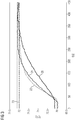
- a course 20 of a control variable which was obtained when using a PI controller as a conventional controller in the control device, a course 21 of a controlled variable using an automatically parameterized model sequence control, a curve 22 of a calculated in the feedforward trajectory y_Traj and a curve 23 of the setpoint located.
- the abscissa shows the time t in the unit s (seconds), the ordinate the temperature T in the unit ° C.
- the illustrated curves 20 ... 23 were with the already described above Temperature control of a reactor obtained as a controlled system. By means of several jump excitations, the dynamic behavior of the reactor was identified and a model family generated from the inaccuracies.
- the parameterization of the model sequence control was carried out automatically according to the method described above.
- a sudden change in the temperature setpoint from 70 ° C to 72 ° C at time t 0 s was evaluated. After a dead time of about 30 s, all gradients 20, 21 and 22 of the temperature increase as a controlled variable. The time until the new setpoint temperature of 72 ° C is reached to an accuracy of 0.1 K, is in the classic PI controller with the curve 20 about 300 s.
- the model-following control regulates the new setpoint much faster and reaches the tolerance band after about 198 seconds. In an advantageous manner, no special expertise was required for the parameterization of the control device designed as a model sequence controller, so that the parameterization can be carried out by each user.
- the leadership behavior can namely significantly compared to a classic PI controller and also significantly improved over a classic PID controller as a control device.
Landscapes
- Engineering & Computer Science (AREA)
- Physics & Mathematics (AREA)
- General Physics & Mathematics (AREA)
- Automation & Control Theory (AREA)
- Health & Medical Sciences (AREA)
- Artificial Intelligence (AREA)
- Computer Vision & Pattern Recognition (AREA)
- Evolutionary Computation (AREA)
- Medical Informatics (AREA)
- Software Systems (AREA)
- Feedback Control In General (AREA)
Priority Applications (5)
| Application Number | Priority Date | Filing Date | Title |
|---|---|---|---|
| EP16199391.0A EP3324254A1 (fr) | 2016-11-17 | 2016-11-17 | Dispositif et procédé de détermination des paramètres d'un dispositif de réglage |
| CN201780071248.9A CN109964180B (zh) | 2016-11-17 | 2017-11-16 | 用于确定调节装置的参数的装置和方法 |
| US16/461,618 US11086277B2 (en) | 2016-11-17 | 2017-11-16 | System and method for determining the parameters of a controller |
| EP17809212.8A EP3542229B1 (fr) | 2016-11-17 | 2017-11-16 | Dispositif et procédé de détermination des paramètres d'un dispositif de réglage |
| PCT/EP2017/079482 WO2018091592A1 (fr) | 2016-11-17 | 2017-11-16 | Dispositif et procédé de détermination des paramètres d'un dispositif de régulation |
Applications Claiming Priority (1)
| Application Number | Priority Date | Filing Date | Title |
|---|---|---|---|
| EP16199391.0A EP3324254A1 (fr) | 2016-11-17 | 2016-11-17 | Dispositif et procédé de détermination des paramètres d'un dispositif de réglage |
Publications (1)
| Publication Number | Publication Date |
|---|---|
| EP3324254A1 true EP3324254A1 (fr) | 2018-05-23 |
Family
ID=57460309
Family Applications (2)
| Application Number | Title | Priority Date | Filing Date |
|---|---|---|---|
| EP16199391.0A Withdrawn EP3324254A1 (fr) | 2016-11-17 | 2016-11-17 | Dispositif et procédé de détermination des paramètres d'un dispositif de réglage |
| EP17809212.8A Active EP3542229B1 (fr) | 2016-11-17 | 2017-11-16 | Dispositif et procédé de détermination des paramètres d'un dispositif de réglage |
Family Applications After (1)
| Application Number | Title | Priority Date | Filing Date |
|---|---|---|---|
| EP17809212.8A Active EP3542229B1 (fr) | 2016-11-17 | 2017-11-16 | Dispositif et procédé de détermination des paramètres d'un dispositif de réglage |
Country Status (4)
| Country | Link |
|---|---|
| US (1) | US11086277B2 (fr) |
| EP (2) | EP3324254A1 (fr) |
| CN (1) | CN109964180B (fr) |
| WO (1) | WO2018091592A1 (fr) |
Cited By (1)
| Publication number | Priority date | Publication date | Assignee | Title |
|---|---|---|---|---|
| WO2020049051A3 (fr) * | 2018-09-05 | 2020-05-14 | Siemens Aktiengesellschaft | Paramétrage automatisé d'un régulateur |
Families Citing this family (3)
| Publication number | Priority date | Publication date | Assignee | Title |
|---|---|---|---|---|
| EP3859458A1 (fr) * | 2020-01-31 | 2021-08-04 | Robert Bosch GmbH | Procédé et dispositif de conception d'un circuit de régulation |
| EP3882722A1 (fr) | 2020-03-19 | 2021-09-22 | Siemens Aktiengesellschaft | Fabrication ou commande d'un système technique à l'aide d'un ensemble de paramètres optimisé |
| CN113672002B (zh) * | 2021-08-23 | 2022-03-22 | 九江学院 | 一种基于名义模型的冷原子重力仪主动隔振控制方法 |
Citations (4)
| Publication number | Priority date | Publication date | Assignee | Title |
|---|---|---|---|---|
| EP0520233A2 (fr) | 1991-06-24 | 1992-12-30 | Siemens Aktiengesellschaft | Dispositif pour l'identification d'un système commandé |
| WO2001098845A1 (fr) * | 2000-06-20 | 2001-12-27 | Fisher-Rosemount Systems, Inc. | Regulateur proportionnel-integral-derive (pid) adaptatif de recuperation-anticipation |
| US20050096793A1 (en) * | 2003-10-30 | 2005-05-05 | Kabushiki Kaisha Toshiba | Reference model tracking control system and method |
| US20130035914A1 (en) * | 2010-04-26 | 2013-02-07 | Mitsubishi Electric Corporation | Servo controller |
Family Cites Families (25)
| Publication number | Priority date | Publication date | Assignee | Title |
|---|---|---|---|---|
| DE19641431A1 (de) * | 1996-10-08 | 1998-04-16 | Siemens Ag | Verfahren und Einrichtung zur Identifikation bzw. Vorausberechnung von Prozeßparametern eines industriellen zeitvarianten Prozesses |
| FR2792746B1 (fr) * | 1999-04-21 | 2003-10-17 | Ingmar Adlerberg | PROCEDE ET AUTOMATISME DE REGULATION D'UNE PRODUCTION INDUSTRIELLE ETAGEE AVEC MAITRISE D'UN STRESS ENCHAINE ALEATOIRE, APPLICATION AU CONTROLE DU BRUIT ET DU RISQUE VaR D'UNE CHAMBRE DE COMPENSATION |
| US6826521B1 (en) * | 2000-04-06 | 2004-11-30 | Abb Automation Inc. | System and methodology and adaptive, linear model predictive control based on rigorous, nonlinear process model |
| US9400921B2 (en) * | 2001-05-09 | 2016-07-26 | Intel Corporation | Method and system using a data-driven model for monocular face tracking |
| DE10129141A1 (de) * | 2001-06-16 | 2002-12-19 | Abb Research Ltd | Steuer- und Regelverfahren un Regeleinrichtung zum An- oder Abfahren einer verfahrenstechnischen Komponente eines technischen Prozesses |
| JP3922980B2 (ja) * | 2001-07-25 | 2007-05-30 | 本田技研工業株式会社 | 制御装置 |
| ITVE20010036A1 (it) * | 2001-08-08 | 2003-02-08 | Fpt Ind Spa | Metodo per effettuare in modo automatico la correzione degli errori sistematici in macchine di misura ed in macchine operatrici ed apparecch |
| US7103508B2 (en) * | 2002-09-25 | 2006-09-05 | Benesse Corporation | Test system and control method |
| FR2863080B1 (fr) * | 2003-11-27 | 2006-02-24 | Advestigo | Procede d'indexation et d'identification de documents multimedias |
| CN1965332A (zh) * | 2004-02-20 | 2007-05-16 | 西门子共同研究公司 | 利用鲁棒信息融合来基于多模组成部分地跟踪对象的方法和系统 |
| DE102006047718A1 (de) * | 2006-10-09 | 2008-04-17 | Siemens Ag | Verfahren zur Nachverfolgung des physikalischen Zustands eines Warmblechs oder Warmbands im Rahmen der Steuerung einer Grobblechwalzstraße zur Bearbeitung eines Warmblechs oder Warmbands |
| CN101339406B (zh) * | 2007-07-04 | 2011-05-11 | 中国科学院自动化研究所 | 一种自适应控制器及方法 |
| US8868221B1 (en) * | 2008-08-22 | 2014-10-21 | Marvell International Ltd. | Adaptive neural net feed forward system and method for adaptive control of mechanical systems |
| CN101604447B (zh) * | 2009-07-09 | 2011-06-01 | 上海交通大学 | 无标记人体运动捕捉方法 |
| US10409232B2 (en) * | 2010-03-29 | 2019-09-10 | Siemens Aktiengesellschaft | Engineering tool and method for parameterizing a model-based predictive controller |
| US8412357B2 (en) * | 2010-05-10 | 2013-04-02 | Johnson Controls Technology Company | Process control systems and methods having learning features |
| CN102269971A (zh) * | 2010-06-01 | 2011-12-07 | 嘉善东菱电子科技有限公司 | 基于模型跟踪的自适应伺服控制器 |
| JP5726328B2 (ja) * | 2011-11-22 | 2015-05-27 | 三菱電機株式会社 | モータ制御装置 |
| CN104281055A (zh) * | 2014-03-18 | 2015-01-14 | 江南大学 | 一种连续搅拌聚丙烯反应釜温度的自抗扰控制方法 |
| EP3012233A1 (fr) * | 2014-10-23 | 2016-04-27 | Siemens Aktiengesellschaft | Dispositif et procédé de régulation d'une installation d'eaux usées |
| CN104466681B (zh) * | 2014-11-25 | 2018-12-25 | 武汉光迅科技股份有限公司 | 一种光纤放大器的串级控制系统 |
| CN104991444B (zh) * | 2015-07-30 | 2018-02-09 | 湖南工业大学 | 基于跟踪微分器的非线性pid自适应控制方法 |
| JP6519457B2 (ja) * | 2015-11-30 | 2019-05-29 | オムロン株式会社 | 補正装置、補正装置の制御方法、情報処理プログラム、および記録媒体 |
| CN105522578B (zh) * | 2015-12-29 | 2017-12-08 | 汇川技术(东莞)有限公司 | 面向零力控制的模拟转矩控制方法以及系统 |
| EP3232282B1 (fr) * | 2016-04-12 | 2018-09-12 | Siemens Aktiengesellschaft | Dispositif de diagnostic et procede de surveillance du fonctionnement d'une installation technique |
-
2016
- 2016-11-17 EP EP16199391.0A patent/EP3324254A1/fr not_active Withdrawn
-
2017
- 2017-11-16 WO PCT/EP2017/079482 patent/WO2018091592A1/fr not_active Ceased
- 2017-11-16 CN CN201780071248.9A patent/CN109964180B/zh not_active Expired - Fee Related
- 2017-11-16 US US16/461,618 patent/US11086277B2/en not_active Expired - Fee Related
- 2017-11-16 EP EP17809212.8A patent/EP3542229B1/fr active Active
Patent Citations (4)
| Publication number | Priority date | Publication date | Assignee | Title |
|---|---|---|---|---|
| EP0520233A2 (fr) | 1991-06-24 | 1992-12-30 | Siemens Aktiengesellschaft | Dispositif pour l'identification d'un système commandé |
| WO2001098845A1 (fr) * | 2000-06-20 | 2001-12-27 | Fisher-Rosemount Systems, Inc. | Regulateur proportionnel-integral-derive (pid) adaptatif de recuperation-anticipation |
| US20050096793A1 (en) * | 2003-10-30 | 2005-05-05 | Kabushiki Kaisha Toshiba | Reference model tracking control system and method |
| US20130035914A1 (en) * | 2010-04-26 | 2013-02-07 | Mitsubishi Electric Corporation | Servo controller |
Cited By (1)
| Publication number | Priority date | Publication date | Assignee | Title |
|---|---|---|---|---|
| WO2020049051A3 (fr) * | 2018-09-05 | 2020-05-14 | Siemens Aktiengesellschaft | Paramétrage automatisé d'un régulateur |
Also Published As
| Publication number | Publication date |
|---|---|
| CN109964180B (zh) | 2022-06-14 |
| CN109964180A (zh) | 2019-07-02 |
| US11086277B2 (en) | 2021-08-10 |
| EP3542229A1 (fr) | 2019-09-25 |
| EP3542229B1 (fr) | 2020-09-30 |
| WO2018091592A1 (fr) | 2018-05-24 |
| US20200064787A1 (en) | 2020-02-27 |
Similar Documents
| Publication | Publication Date | Title |
|---|---|---|
| DE2735012C2 (fr) | ||
| DE102004058238B4 (de) | Adaptive, multivariable Prozesssteuerung, die Modellschaltung und Attribut-Interpolation nutzt | |
| DE102004019352B4 (de) | Zustandsbasierter adaptiver Feedback-/Feedforward-PID-Regler (PID-Steuerungseinheit) | |
| DE3650164T2 (de) | Prozessregler mit einem System zur Einstellung mit zwei Freiheitsgraden. | |
| DE10341764A1 (de) | Integrierte Modell-Vorhersagesteuerung und -Optimierung innerhalb eines Prozesssteuerungssystems | |
| EP3542229B1 (fr) | Dispositif et procédé de détermination des paramètres d'un dispositif de réglage | |
| DE1673566A1 (de) | Verfahren und Vorrichtung zur Einstellung mehrerer ausgewaehlter Bestimmungsgroessen eines Reglers fuer industrielle Verfahrensablaeufe | |
| DE102011012710A1 (de) | Schnelle Identifikation und Erzeugung von Prozessmodellen | |
| DE3311048A1 (de) | Regelverfahren und -einrichtung | |
| DE69106031T2 (de) | Regler mit zwei Freiheitsgraden. | |
| EP0520233B1 (fr) | Dispositif pour l'identification d'un système commandé | |
| EP1150186A1 (fr) | Optimision en ligne basée sur un modéle | |
| DE3721504C2 (de) | Regelsystem | |
| DE1523535C3 (de) | Selbstanpassender Regelkreis | |
| EP0561813B1 (fr) | Procede pour la determination de parametres de commande pilote pour une regulation de position | |
| DE69109159T2 (de) | Prozessregelungsvorrichtung. | |
| WO2010003726A1 (fr) | Système de conduite d'une installation avec optimisation du modèle en plusieurs phases | |
| EP0752630A1 (fr) | ContrÔleur auto-ajustable et méthode pour l'auto-ajustement du contrÔleur | |
| EP4275099B1 (fr) | Procédé et systèmes de détermination des paramètres de compensation | |
| DE102021116388A1 (de) | Verfahren zum Optimieren eines Reglers und Regelsystem mit einem derart optimierten Regler | |
| DE19825859A1 (de) | Kompensationseinrichtung, Verfahren und Stelleinrichtung zur Kompensation von Kriech- und Hystereseeffekten im Übertragungsverhalten von Stellgliedern | |
| EP0996875B1 (fr) | Procede de reglage de plusieurs regulateurs pour la regulation d'un systeme d'automatisme asservi constitue de systemes regles couples | |
| DE3618025A1 (de) | Vorrichtung zur bestimmung der regelguete und der stabilitaet von regelkreisen aus messwerten und kennwerten des regelkreises | |
| DE1673586C3 (de) | Verfahren zur Einstellung eines Regelkreises | |
| EP1249742B1 (fr) | Procédé de régulation de débit dans une conduite et dispositif de régulation servant à mettre en oeuvre le procédé |
Legal Events
| Date | Code | Title | Description |
|---|---|---|---|
| PUAI | Public reference made under article 153(3) epc to a published international application that has entered the european phase |
Free format text: ORIGINAL CODE: 0009012 |
|
| AK | Designated contracting states |
Kind code of ref document: A1 Designated state(s): AL AT BE BG CH CY CZ DE DK EE ES FI FR GB GR HR HU IE IS IT LI LT LU LV MC MK MT NL NO PL PT RO RS SE SI SK SM TR |
|
| AX | Request for extension of the european patent |
Extension state: BA ME |
|
| STAA | Information on the status of an ep patent application or granted ep patent |
Free format text: STATUS: THE APPLICATION IS DEEMED TO BE WITHDRAWN |
|
| 18D | Application deemed to be withdrawn |
Effective date: 20181124 |