EP3324261B1 - Robot automatique de tondeuse et procédé de commande associé - Google Patents
Robot automatique de tondeuse et procédé de commande associé Download PDFInfo
- Publication number
- EP3324261B1 EP3324261B1 EP17201833.5A EP17201833A EP3324261B1 EP 3324261 B1 EP3324261 B1 EP 3324261B1 EP 17201833 A EP17201833 A EP 17201833A EP 3324261 B1 EP3324261 B1 EP 3324261B1
- Authority
- EP
- European Patent Office
- Prior art keywords
- lawn mower
- area
- data
- remote memory
- robots
- Prior art date
- Legal status (The legal status is an assumption and is not a legal conclusion. Google has not performed a legal analysis and makes no representation as to the accuracy of the status listed.)
- Active
Links
Images

Classifications
-
- G—PHYSICS
- G05—CONTROLLING; REGULATING
- G05D—SYSTEMS FOR CONTROLLING OR REGULATING NON-ELECTRIC VARIABLES
- G05D1/00—Control of position, course, altitude or attitude of land, water, air or space vehicles, e.g. using automatic pilots
- G05D1/02—Control of position or course in two dimensions
- G05D1/021—Control of position or course in two dimensions specially adapted to land vehicles
- G05D1/0212—Control of position or course in two dimensions specially adapted to land vehicles with means for defining a desired trajectory
- G05D1/0219—Control of position or course in two dimensions specially adapted to land vehicles with means for defining a desired trajectory ensuring the processing of the whole working surface
-
- A—HUMAN NECESSITIES
- A01—AGRICULTURE; FORESTRY; ANIMAL HUSBANDRY; HUNTING; TRAPPING; FISHING
- A01D—HARVESTING; MOWING
- A01D34/00—Mowers; Mowing apparatus of harvesters
- A01D34/006—Control or measuring arrangements
- A01D34/008—Control or measuring arrangements for automated or remotely controlled operation
-
- G—PHYSICS
- G05—CONTROLLING; REGULATING
- G05D—SYSTEMS FOR CONTROLLING OR REGULATING NON-ELECTRIC VARIABLES
- G05D1/00—Control of position, course, altitude or attitude of land, water, air or space vehicles, e.g. using automatic pilots
- G05D1/02—Control of position or course in two dimensions
- G05D1/021—Control of position or course in two dimensions specially adapted to land vehicles
- G05D1/0259—Control of position or course in two dimensions specially adapted to land vehicles using magnetic or electromagnetic means
- G05D1/0265—Control of position or course in two dimensions specially adapted to land vehicles using magnetic or electromagnetic means using buried wires
-
- G—PHYSICS
- G05—CONTROLLING; REGULATING
- G05D—SYSTEMS FOR CONTROLLING OR REGULATING NON-ELECTRIC VARIABLES
- G05D1/00—Control of position, course, altitude or attitude of land, water, air or space vehicles, e.g. using automatic pilots
- G05D1/02—Control of position or course in two dimensions
- G05D1/021—Control of position or course in two dimensions specially adapted to land vehicles
- G05D1/0268—Control of position or course in two dimensions specially adapted to land vehicles using internal positioning means
- G05D1/0274—Control of position or course in two dimensions specially adapted to land vehicles using internal positioning means using mapping information stored in a memory device
Definitions
- This invention relates to an electronic system and the method for automatically controlling a plurality of lawn mower robots according to it.
- Automatic lawn mower robots are prior art devices designed to cut grass without continuous control by the user.
- Automatic lawn mower robots have become widespread in substantially recent times, following the need to cut large areas of grass autonomously, so that user can dedicate him/herself to other activities without losing time continuously checking a lawn mower, for example with motor-driven tractors, since these activities are very time-consuming and, at the same time, not very remunerative. Substantially, therefore, the automatic lawn mower robots have allowed the movement of the intelligence of the user towards activities other than the traditional lawn mowing. Examples of similar lawn mower robots can be found in document EP 2 342 964 and US 2011 112730 .
- the aim of this invention is to provide an automatic lawn mower which overcomes the above-mentioned drawbacks.
- Another aim of this invention is to illustrate a method for coordinating more than one automatic lawn mower, which overcomes the above-mentioned drawbacks.
- Another aim of this invention is to provide an electronic system which overcomes the above-mentioned drawbacks.
- the invention describes an electronic system and a method for automatically controlling a plurality of lawn mowers robots which makes it possible to optimise the lawn cutting strategy in a predetermined area.
- each lawn mower robot comprising:
- the extension and/or the coordinates of at least part of the perimeter of the area is previously stored in the remote memory unit in the electronic system.
- inhibiting areas inside the perimeter of the area are stored in the remote memory unit, the inhibiting areas being:
- the movement strategy is automatically updated over time according to the plurality of parameters, and automatically re-transmitted towards the plurality of lawn mower robots.
- the plurality of sensors measures data of a heterogeneous type used together for redefining over time the movement strategy.
- the movement strategy is variable over time.
- the localisation module comprises satellite global positioning means, and wherein the ambient data comprise global positioning data comprising global latitude and longitude data.
- the senor means also comprise a stereoscopic video camera.
- the sensor means comprise moisture and/or temperature sensors.
- the invention describes a method for automatically controlling a plurality of lawn mower robots inside an area according to claim 8.
- the combined parameters in the method comprise at least one definition of at least one inhibiting sub-area within the perimeter of the area, and wherein the at least one inhibiting sub-area is loaded in the remote memory with:
- the method comprises a step of automatic updating of the movement strategy according to the plurality of parameters, and a step for transmitting the updated movement strategy towards the plurality of lawn mower robots.
- the plurality of sensors in the method measures data of a heterogeneous type used together for redefining over time the movement strategy.
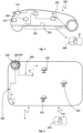
- the reference numeral 100 in Figure 1 denotes an automatic lawn mower robot which is in use positioned on a lawn or grassy area defined by a surface or area A having its own delimiting perimeter, and within which there is grass to be cut together with any obstacles.
- the automatic lawn mower robot 100 is designed to autonomously move within the area A in order to cut the grass present in the same area. More specifically, as illustrated in Figure 2 , inside the lawn area A there may be more than one lawn mower robot 100, as will be described in detail below, operating simultaneously or not.
- autonomous means a movement substantially not guided by the user, that is to say, a movement which comprises the activation or deactivation of the movement means by a process substantially predetermined and/or updated in an autonomous manner by data processing means according to a plurality of ambient parameters autonomously acquired electronically by sensors.
- the lawn mower robot 100 comprises a movement motor 101 which allows it to be moved along a straight or curved trajectory forwards or backwards, preferably of the electrical type and powered by a battery.
- the same battery also powers the cutting means 102 which typically comprise one or more blades rotating in a shared or counter-rotating fashion, positioned in contact with or close to the ground and, in detail, in such a way that the axis of rotation is substantially at right angles to the ground.
- the blades rotating in use cut the grass the height of which exceeds the height at which they are positioned and the convey the grass by known means towards a drum or, alternatively, they leave it deposited on the lawn itself.
- the battery charge is advantageously controlled electronically in such a way as to prevent the battery draining completely before the robot has returned to the base or starting position in which the recharging unit is conveniently installed. More specifically, when a particularly low charge is detected, switching means of known type switch OFF the motor powering the cutting means 102.
- the lawn mower robot 100 is a robot whose cutting strategy is adapted according to a plurality of external and ambient conditions, starting from a predetermined strategy which is automatically adapted over time, and is therefore a strategy variable over time.
- the movement strategy or cutting strategy means the prior programming of a movement path of one or more lawn mower robots 100 within the lawn area A, and subsequent activation of the movement means 101 in accordance with the prior programming.
- the movement strategy variable over time or the cutting strategy variable over time means that the movement strategy or the cutting strategy is adapted automatically by data processing means according to electronic data captured in real time from sensor means, in such a way as to vary the movement path of the one or more lawn mower robots 100 relative to the movement path programmed in advance.
- the automatic lawn mower robot 100 also comprises sensor means which assist the definition of its position, as well as the detection of obstacles and allow a better operation in the strategy of mowing the lawn.
- the sensor means comprise above all contact or proximity sensors 103, positioned at least in front of the body of the lawn mower robot 100.
- the contact or proximity sensors 103 are radar sensors or impact sensors (for example, comprising mechanical switches) or Hall effect sensors (for example, comprising a mechanical part movable relative to a second fixed part, wherein the movable part of the sensor preferably comprises a magnet and the fixed part comprises a Hall effect detector; or vice versa).
- These contact or proximity sensors 103 are configured to detect the presence of an obstacle which comes close to the robot during the forward movement and advantageously command the stopping in front of an obstacle. This allows a greater flexibility of use of the lawn mower robot 100, which may be used without problems in lawns with obstacles, such as, for example and without limiting the scope of the invention, plants and shrubs.
- the contact or proximity sensors 103 are assisted or replaced by a stereoscopic video camera 110, which is designed to allow the detection of objects around the body of the lawn mower robot 100 by means of a software reading of the approach of objects.
- Both the contact or proximity sensors 103 and the stereoscopic video camera 110 when present, are electrically connected to a data processing unit present on board the lawn mower robot 100.
- the data processing unit can be conveniently designed starting from a specifically designed general purpose processor or from a dedicated processor, or - where the technology allows it - through a FPGA, or even through a microcomputer such as, for example but without limiting the invention, a Raspberry or the like.
- the data processing unit is programmed to receive the ambient data coming from the contact or proximity sensors 103 and from the stereoscopic video camera 110, if installed, and to execute a processing of the data aimed at defining a position in the area A of the obstacles detected by them. This, as described in more detail below, advantageously allows a greater flexibility and efficiency in the definition of the cutting strategy of the lawn.
- the lawn mower robot 100 also has a control of the geographical position adopted in real time. For this reason, it comprises a localisation module 105 conveniently using a GPS/GLONASS satellite receiver which is able to allow positioning of the lawn mower robot 100 with a pair of longitude/latitude coordinates which define ambient positioning data 109 of the time-variant type, precisely on account of the movement of the robot itself in the area A.
- a localisation module 105 conveniently using a GPS/GLONASS satellite receiver which is able to allow positioning of the lawn mower robot 100 with a pair of longitude/latitude coordinates which define ambient positioning data 109 of the time-variant type, precisely on account of the movement of the robot itself in the area A.
- the lawn mower robot 100 also comprises temperature and moisture sensors 104. These sensors use a technology of known type and are also electrically connected to the data processing unit.
- the lawn mower robot 100 also comprises a radio module 106, electrically connected to the data processing unit and configured for transmitting at least the ambient data indicating the presence of obstacles 107, ambient temperature and moisture data 108 and the ambient global positioning data 109 towards a remote memory unit 200, accessible preferably by means of coded communication according to prior art, in order to prevent interference.
- the radio module can operate with Wi-Fi technology, or even on a dedicated radio channel, with point-multipoint transmission or according to any mobile phone standard.
- the automatic lawn mower robots 100 also comprise a shear force sensor.
- the sensor of known type and installed on the electric cutting motor, measures the effort exerted by the electric motor (typically by the absorption of electric current) and indirectly allows the density and/or height of the lawn to be known. It has been found that by means of an instantaneous correction of the speed of forward movement of the lawn mower robot 100 according to the cutting force it is possible to achieve a better quality of mowing. This in fact occurs in particular when the forward speed of the mowing is reduced in proportion to the increase in the cutting force.
- the automatic lawn mower robot 100 described above is in fact introduced in a more general context of an electronic system for mowing lawns designed for allowing the coordination of several lawn mower robots 100 such as the one described above, in such a way as to automatically adapt the movement strategy.
- the system in addition to the plurality of automatic lawn mower robot 100 positioned in the area A, also comprises a remote memory unit 200 electrically connected to its own electronic processor and accessible remotely via radio from the radio module of the lawn mower robot 100.
- the function of the remote memory unit 200 is to allow the computational intelligence of the strategy for cutting grass in the area A to be shifted out from the data processing units installed on board the lawn mower robot 100.
- This feature advantageously makes it possible to make the data processing units installed on board the lawn mower robot 100 more economic and less complex to make and program, leaving the majority of the computational duties to the electronic processor installed in the remote memory unit 200, which advantageously, but without limiting the scope of the invention, may be considered as a cloud type storage unit.
- the remote memory unit 200 is accessible on a wireless channel, by means of a radio modem directly connected to it or, alternatively, connected to the electronic processor associated with it.
- the remote memory unit 200 stores a series of operational parameters which also comprise the ambient data gradually transmitted by the lawn mower robot 100 during its movement inside the A.
- the electronic processor associated with remote memory unit 200 processes a cutting strategy which advantageously comprises at least one path 300 to be followed by the lawn mower robot 100.
- the cutting strategy processed by the electronic processor associated with the remote memory unit 200 is adapted over time.
- the path 300 is advantageously firstly predetermined on the basis of the shape of the perimeter of the area A, and calculated electronically by the electronic processor in such a way that two separate lawn mower robots 100 do not pass repeatedly on zones of the area A that have already been cut by another robot.
- this makes it possible to reduce the waste of time and save the electrical energy of the batteries of the robots, without using it unnecessarily for the cutting of zones of the area A where the grass has already been cut.
- the path 300 which must be followed by the lawn mower robots 100 is updated over time according to the actual path followed by the other lawn mower robots 100. This may occur both whilst several lawn mower robots 100 are active in the area A at the same time and whilst one lawn mower robot 100 at a time is active in the area A.
- the lawn mower robots 100 described above are equipped with the optional localisation module 105, at least two lawn mower robots 100 may be left to operate inside the area A simultaneously with a further reduction in the risk that they could strike each other.
- the lawn mower robots 100 are controlled in real time through the remote memory unit 200, which updates at set times the cutting strategy for the two lawn mower robots 100 according to any variations in the cutting strategy with respect to that originally defined, and namely according to the presence of obstacles detected by the robots or slow-downs or bends, or deviations from the theoretical mowing speed due to zonal increases in the cutting force.
- the temperature data collected by the remote memory unit 200 advantageously allow checking if the conditions exist to be able to perform the cutting, and namely if:
- the method for controlling the operation of more than one lawn mower robot 100 might be performed as follows:
- the cycle of sending ambient data and if necessary modifying the cutting strategy is repeated (block 1006, arrow 1007) until the entire area A has been cut (block 1008), after which the lawn mower robots 100 are stopped in a consonant manner and, preferably but without limiting the invention, returned to the battery recharging station so that they can be again ready for use at a later time.
- the presence of sensor means of the ambient conditions advantageously allows the cutting strategy to be optimised not only in accordance to the position of the robots in the area A, but also in accordance with the ambient conditions detected at the particular moment, making it possible, for example, to interrupt or delay the cutting of all or part of the area A precisely accordance with the ambient conditions automatically detected, so that the effectiveness in terms of cutting capacity and the result of the cutting, also in terms of health of the lawn, can be optimised automatically without the intervention of the user.
Landscapes
- Engineering & Computer Science (AREA)
- Radar, Positioning & Navigation (AREA)
- Physics & Mathematics (AREA)
- Aviation & Aerospace Engineering (AREA)
- Remote Sensing (AREA)
- General Physics & Mathematics (AREA)
- Automation & Control Theory (AREA)
- Life Sciences & Earth Sciences (AREA)
- Environmental Sciences (AREA)
- Electromagnetism (AREA)
- Harvester Elements (AREA)
- Control Of Position, Course, Altitude, Or Attitude Of Moving Bodies (AREA)
Claims (9)
- Système électronique, comprenant une unité de mémoire distante (200) et plusieurs robots de tondeuse (100) accédant à distance à l'unité de mémoire distante (200), chaque robot de tondeuse (100) comprenant :- au moins un moteur électrique (101) conçu pour permettre le déplacement du robot de manière sensiblement automatique ;- un dispositif de coupe de l'herbe (102), placé dans une position substantiellement en contact, en cours d'utilisation, avec un gazon à tondre ; et- une pluralité de capteurs (103, 104, 110), comprenant :
des capteurs de contact ou de proximité (103) fixés sur le corps du robot de tondeuse (100) et conçus pour identifier la présence d'obstacles autour du robot de tondeuse (100), et- des capteurs de force de tonte, installés sur le moteur électrique (101 agencé pour mesurer l'effort exercé par le moteur électrique et permettre de connaître la densité et/ou la hauteur de la pelouse ;- un module de localisation (105), permettant la localisation géographique du robot de tondeuse (100) à l'intérieur d'une zone (A) par l'acquisition de données de position (109), le module de localisation (105) étant interfacé électroniquement avec l'au moins un moteur (101) et commandant sélectivement la mise en marche et l'arrêt du moteur électrique (101) ; et- des moyens de détection de l'humidité et/ou de la température (104) conçus pour mesurer la température ambiante et les données relatives à l'humidité ; et- un module émetteur-récepteur de données (106), conçu pour permettre l'envoi de données ambiantes (107, 108, 109),dans lequel les données ambiantes comprennent des données d'obstacle (107), de température ambiante et d'humidité (108) et des données de position (109) acquises électroniquement par ladite pluralité de capteurs (103, 104, 110) et le module de localisation (105), à l'unité de mémoire distante (200) ;et dans lequel l'unité de mémoire distante comprend un moyen de calculer une stratégie de mouvement pour déplacer la pluralité de robots de tondeuse (100) ;dans lequel la stratégie de déplacement est définie au moins en fonction des paramètres combinés stockés dans l'unité de mémoire distante (200), des données ambiantes (107, 108, 109) et des données de position acquises de manière autonome par chacun des robots de tondeuse (100) dans la zone (A) ;dans lequel la stratégie de déplacement est automatiquement mise à jour dans le temps en fonction de la pluralité de paramètres, et automatiquement retransmise à la pluralité de robots de tondeuse (100). - Système électronique selon la revendication 1, dans lequel une extension et/ou des coordonnées d'au moins une partie d'un périmètre de la zone (A) sont préalablement stockées dans l'unité de mémoire distante (200) .
- Système électronique selon la revendication 1, dans lequel des zones d'inhibition à l'intérieur d'un périmètre de la zone (A) sont stockées dans l'unité de mémoire distante (200), les zones d'inhibition étant :- chargées manuellement dans la mémoire distante (200), et/ou- stockées progressivement en fonction de la pluralité de données ambiantes (107, 108, 109).
- Système électronique selon l'une quelconque des revendications précédentes,
dans lequel le robot de tondeuse (100) active le moteur électrique (101) pour se déplacer sur la zone (A) selon la stratégie de déplacement définie au moins selon lesdites données ambiantes (107, 108, 109), selon des paramètres combinés stockés dans l'unité de mémoire distante (200) et selon la position adoptée dans la zone (A) par les autres robots de tondeuse (100). - Système électronique selon la revendication 4, dans lequel la stratégie de mouvement est variable dans le temps.
- Système électronique selon la revendication 5, caractérisé en ce que le module de localisation (105) comprend des moyens de positionnement global par satellite, et dans lequel les données ambiantes (109) comprennent des données de positionnement global comprenant des données de latitude et de longitude globales.
- Système électronique selon la revendication 4, dans lequel la pluralité de moyens de détection (103, 104, 110) comprend également une caméra vidéo stéréoscopique (110) .
- Procédé pour commander automatiquement une pluralité de robots de tondeuse (100) à l'intérieur d'une zone (A), la pluralité de robots de tondeuse (100) présentant les caractéristiques selon une ou plusieurs des revendications 1 à 7 ;le procédé comprenant une étape de stocker des paramètres combinés dans une mémoire distante (200), accessible à distance par la pluralité de robots de tondeuse (100) et une étape pour transmettre au moins une partie des paramètres combinés de la mémoire distante (200) à un ou plusieurs robots de tondeuse (100),et dans lequel une stratégie pour déplacer la pluralité de robots de tondeuse automatiques (100) dans la zone (A) consiste à :- identifier la présence d'obstacles autour de chaque robot de tondeuse (100) ;- des capteurs de force de tonte afin de mesurer l'effort exercé par le moteur électrique et de permettre de connaître la densité et/ou la hauteur de la pelouse ;- acquérir des données de position (109) afin de localiser le robot de tondeuse (100) à l'intérieur de la zone (A) au moyen d'une interface électronique avec l'au moins un moteur (101) et à travers une commande sélective de la mise en marche et de l'arrêt du moteur électrique (101) ;- mesurer la température ambiante et l'humidité de la zone (A) ;- envoyer les données ambiantes (107, 108, 109) de la zone (A), dans lequel les données ambiantes comprennent des données d'obstacle (107), de température ambiante et d'humidité (108) et des données de position (109) ;- calculer une stratégie de mouvement pour déplacer la pluralité de robots de tondeuse (100), ladite stratégie de mouvement étant définie au moins selon des paramètres combinés stockés dans l'unité de mémoire distante (200) et des données ambiantes (107, 108, 109) et des données de position acquises de manière autonome par chacun d'entre eux selon une donnée de position (109) adoptée par le robot de tondeuse (100) dans la zone (A).
- Procédé selon la revendication 8, dans lequel les paramètres combinés comprennent au moins une définition d'au moins une sous-zone d'inhibition à l'intérieur du périmètre de la zone (A), et dans lequel au moins une sous-zone d'inhibition est chargée dans la mémoire distante (200) avec :- une étape pour la définition manuelle par l'utilisateur utilisant un dispositif électronique accédant électroniquement à l'unité de mémoire ; et/ou- une étape de stockage progressif selon la pluralité de données ambiantes (107, 108, 109).
Applications Claiming Priority (1)
| Application Number | Priority Date | Filing Date | Title |
|---|---|---|---|
| IT102016000116383A IT201600116383A1 (it) | 2016-11-17 | 2016-11-17 | Robot tagliaerba automatico e metodo di controllo associato |
Publications (2)
| Publication Number | Publication Date |
|---|---|
| EP3324261A1 EP3324261A1 (fr) | 2018-05-23 |
| EP3324261B1 true EP3324261B1 (fr) | 2023-05-24 |
Family
ID=58266101
Family Applications (1)
| Application Number | Title | Priority Date | Filing Date |
|---|---|---|---|
| EP17201833.5A Active EP3324261B1 (fr) | 2016-11-17 | 2017-11-15 | Robot automatique de tondeuse et procédé de commande associé |
Country Status (2)
| Country | Link |
|---|---|
| EP (1) | EP3324261B1 (fr) |
| IT (1) | IT201600116383A1 (fr) |
Families Citing this family (15)
| Publication number | Priority date | Publication date | Assignee | Title |
|---|---|---|---|---|
| CN110945997A (zh) * | 2018-09-27 | 2020-04-03 | 苏州宝时得电动工具有限公司 | 自动割草机及其操作控制方法、装置和电子设备 |
| EP3896627B1 (fr) * | 2019-02-26 | 2025-04-02 | Honda Motor Co., Ltd. | Système de travail automatisé |
| CN109828584A (zh) * | 2019-03-01 | 2019-05-31 | 重庆润通智能装备有限公司 | 待割草坪移除、添加障碍物后的路径规划方法及系统 |
| WO2021037116A1 (fr) | 2019-08-27 | 2021-03-04 | 南京德朔实业有限公司 | Système de tonte autoporté et procédé de réalisation d'une opération de tonte supplémentaire sur des régions manquées |
| CN112567959B (zh) * | 2019-09-12 | 2024-08-06 | 南京泉峰科技有限公司 | 自行走割草系统及其漏割区域的补充作业的方法 |
| IT201900016934A1 (it) * | 2019-09-23 | 2021-03-23 | Fabrizio Bernini | Robot tagliaerba |
| CN110800451A (zh) * | 2019-12-12 | 2020-02-18 | 江西洪都航空工业集团有限责任公司 | 一种全自主无人割草系统 |
| US20210382476A1 (en) * | 2020-06-05 | 2021-12-09 | Scythe Robotics, Inc. | Autonomous lawn mowing system |
| CN114679950B (zh) * | 2020-12-30 | 2024-03-15 | 南京泉峰科技有限公司 | 用于自驱动设备的数据交互系统及数据交互方法 |
| WO2022143506A1 (fr) * | 2020-12-30 | 2022-07-07 | 格力博(江苏)股份有限公司 | Tondeuse intelligente et ses procédé et système de commande, et support d'enregistrement |
| FI130752B1 (fi) * | 2021-05-31 | 2024-02-26 | Ice Guard Oy | Urheilukentän hoitolaite, hoitojärjestelmä ja menetelmä urheilukentän hoitamiseksi |
| SE546853C2 (en) * | 2021-08-12 | 2025-02-25 | Husqvarna Ab | Robotic working tool system and a method for providing cooperation of robotic working tools in the system |
| CN114868514B (zh) * | 2022-04-13 | 2023-09-29 | 北京航空航天大学 | 一种基于智能割草机器人的草坪3d打印系统和方法 |
| US20240069549A1 (en) * | 2022-08-31 | 2024-02-29 | Positec Power Tools (Suzhou) Co., Ltd. | Island/border distinguishing for a robot lawnmower |
| CN118303206B (zh) * | 2024-05-06 | 2026-01-06 | 杭州浅景环境艺术工程有限公司 | 一种自行避障全域割草装置 |
Family Cites Families (2)
| Publication number | Priority date | Publication date | Assignee | Title |
|---|---|---|---|---|
| US8738238B2 (en) * | 2009-11-12 | 2014-05-27 | Deere & Company | Coordination of vehicle movement in a field |
| US8295979B2 (en) * | 2010-01-06 | 2012-10-23 | Deere & Company | Adaptive scheduling of a service robot |
-
2016
- 2016-11-17 IT IT102016000116383A patent/IT201600116383A1/it unknown
-
2017
- 2017-11-15 EP EP17201833.5A patent/EP3324261B1/fr active Active
Also Published As
| Publication number | Publication date |
|---|---|
| EP3324261A1 (fr) | 2018-05-23 |
| IT201600116383A1 (it) | 2018-05-17 |
Similar Documents
| Publication | Publication Date | Title |
|---|---|---|
| EP3324261B1 (fr) | Robot automatique de tondeuse et procédé de commande associé | |
| CN115279170B (zh) | 一种自动工作系统 | |
| US12082524B2 (en) | Autonomous lawn mower with edger and control method thereof | |
| US11882787B1 (en) | Automatic sensitivity adjustment for an autonomous mower | |
| CN109005874B (zh) | 自主移动绿化区域维护机器人 | |
| KR101573027B1 (ko) | 지능형 무인 제초 로봇 | |
| CN102811604B (zh) | 用于将机器人园林工具引导至预定位置的方法和系统 | |
| CN111601497B (zh) | 自动工作系统、自移动设备及其控制方法 | |
| US11632901B2 (en) | Autonomous travel work machine | |
| EP3798781A1 (fr) | Tondeuse automatique et procédé pour tourner | |
| US11582903B1 (en) | Vision based guidance system and method for lawn mowing devices | |
| EP4000367B1 (fr) | Tondeuse robot à faible consommation d'énergie | |
| CN106444736B (zh) | 自动返回系统及控制方法 | |
| EP3482621B1 (fr) | Robot pour tondre le gazon et son procédé de commande | |
| US11800831B1 (en) | Vision system integration | |
| EP4270137A1 (fr) | Création d'une limite virtuelle pour un outil de jardin robotisé | |
| EP3571915B1 (fr) | Robot pour tondre le gazon | |
| US20240415051A1 (en) | Autonomous Lawn Mower with Edger and Control Method Thereof | |
| WO2023146451A1 (fr) | Fonctionnement amélioré pour un système d'outil de travail robotisé | |
| US20230297119A1 (en) | Controlling movement of a robotic garden tool for docking purposes | |
| EP4332716A2 (fr) | Cartographie d'objets rencontres par un outil de jardin robotisé | |
| US20260128692A1 (en) | Power tool motor control and methods associated therewith | |
| EP4381926A1 (fr) | Fonctionnement amélioré pour un outil de travail robotique | |
| EP4343477A1 (fr) | Système de coupe d'herbe et procédé correspondant | |
| SE545376C2 (en) | Navigation for a robotic work tool system |
Legal Events
| Date | Code | Title | Description |
|---|---|---|---|
| PUAI | Public reference made under article 153(3) epc to a published international application that has entered the european phase |
Free format text: ORIGINAL CODE: 0009012 |
|
| STAA | Information on the status of an ep patent application or granted ep patent |
Free format text: STATUS: THE APPLICATION HAS BEEN PUBLISHED |
|
| AK | Designated contracting states |
Kind code of ref document: A1 Designated state(s): AL AT BE BG CH CY CZ DE DK EE ES FI FR GB GR HR HU IE IS IT LI LT LU LV MC MK MT NL NO PL PT RO RS SE SI SK SM TR |
|
| AX | Request for extension of the european patent |
Extension state: BA ME |
|
| STAA | Information on the status of an ep patent application or granted ep patent |
Free format text: STATUS: REQUEST FOR EXAMINATION WAS MADE |
|
| RBV | Designated contracting states (corrected) |
Designated state(s): AL AT BE BG CH CY CZ DE DK EE ES FI FR GB GR HR HU IE IS IT LI LT LU LV MC MK MT NL NO PL PT RO RS SE SI SK SM TR |
|
| 17P | Request for examination filed |
Effective date: 20180706 |
|
| STAA | Information on the status of an ep patent application or granted ep patent |
Free format text: STATUS: EXAMINATION IS IN PROGRESS |
|
| 17Q | First examination report despatched |
Effective date: 20210305 |
|
| GRAP | Despatch of communication of intention to grant a patent |
Free format text: ORIGINAL CODE: EPIDOSNIGR1 |
|
| STAA | Information on the status of an ep patent application or granted ep patent |
Free format text: STATUS: GRANT OF PATENT IS INTENDED |
|
| INTG | Intention to grant announced |
Effective date: 20221116 |
|
| GRAS | Grant fee paid |
Free format text: ORIGINAL CODE: EPIDOSNIGR3 |
|
| GRAA | (expected) grant |
Free format text: ORIGINAL CODE: 0009210 |
|
| STAA | Information on the status of an ep patent application or granted ep patent |
Free format text: STATUS: THE PATENT HAS BEEN GRANTED |
|
| AK | Designated contracting states |
Kind code of ref document: B1 Designated state(s): AL AT BE BG CH CY CZ DE DK EE ES FI FR GB GR HR HU IE IS IT LI LT LU LV MC MK MT NL NO PL PT RO RS SE SI SK SM TR |
|
| REG | Reference to a national code |
Ref country code: GB Ref legal event code: FG4D |
|
| REG | Reference to a national code |
Ref country code: CH Ref legal event code: EP |
|
| REG | Reference to a national code |
Ref country code: DE Ref legal event code: R096 Ref document number: 602017068964 Country of ref document: DE |
|
| REG | Reference to a national code |
Ref country code: AT Ref legal event code: REF Ref document number: 1569912 Country of ref document: AT Kind code of ref document: T Effective date: 20230615 |
|
| REG | Reference to a national code |
Ref country code: IE Ref legal event code: FG4D |
|
| REG | Reference to a national code |
Ref country code: SE Ref legal event code: TRGR |
|
| REG | Reference to a national code |
Ref country code: LT Ref legal event code: MG9D |
|
| REG | Reference to a national code |
Ref country code: NL Ref legal event code: MP Effective date: 20230524 |
|
| REG | Reference to a national code |
Ref country code: AT Ref legal event code: MK05 Ref document number: 1569912 Country of ref document: AT Kind code of ref document: T Effective date: 20230524 |
|
| PG25 | Lapsed in a contracting state [announced via postgrant information from national office to epo] |
Ref country code: PT Free format text: LAPSE BECAUSE OF FAILURE TO SUBMIT A TRANSLATION OF THE DESCRIPTION OR TO PAY THE FEE WITHIN THE PRESCRIBED TIME-LIMIT Effective date: 20230925 Ref country code: NO Free format text: LAPSE BECAUSE OF FAILURE TO SUBMIT A TRANSLATION OF THE DESCRIPTION OR TO PAY THE FEE WITHIN THE PRESCRIBED TIME-LIMIT Effective date: 20230824 Ref country code: NL Free format text: LAPSE BECAUSE OF FAILURE TO SUBMIT A TRANSLATION OF THE DESCRIPTION OR TO PAY THE FEE WITHIN THE PRESCRIBED TIME-LIMIT Effective date: 20230524 Ref country code: ES Free format text: LAPSE BECAUSE OF FAILURE TO SUBMIT A TRANSLATION OF THE DESCRIPTION OR TO PAY THE FEE WITHIN THE PRESCRIBED TIME-LIMIT Effective date: 20230524 Ref country code: AT Free format text: LAPSE BECAUSE OF FAILURE TO SUBMIT A TRANSLATION OF THE DESCRIPTION OR TO PAY THE FEE WITHIN THE PRESCRIBED TIME-LIMIT Effective date: 20230524 |
|
| REG | Reference to a national code |
Ref country code: DE Ref legal event code: R079 Ref document number: 602017068964 Country of ref document: DE Free format text: PREVIOUS MAIN CLASS: G05D0001020000 Ipc: G05D0001430000 |
|
| PG25 | Lapsed in a contracting state [announced via postgrant information from national office to epo] |
Ref country code: RS Free format text: LAPSE BECAUSE OF FAILURE TO SUBMIT A TRANSLATION OF THE DESCRIPTION OR TO PAY THE FEE WITHIN THE PRESCRIBED TIME-LIMIT Effective date: 20230524 Ref country code: PL Free format text: LAPSE BECAUSE OF FAILURE TO SUBMIT A TRANSLATION OF THE DESCRIPTION OR TO PAY THE FEE WITHIN THE PRESCRIBED TIME-LIMIT Effective date: 20230524 Ref country code: LV Free format text: LAPSE BECAUSE OF FAILURE TO SUBMIT A TRANSLATION OF THE DESCRIPTION OR TO PAY THE FEE WITHIN THE PRESCRIBED TIME-LIMIT Effective date: 20230524 Ref country code: LT Free format text: LAPSE BECAUSE OF FAILURE TO SUBMIT A TRANSLATION OF THE DESCRIPTION OR TO PAY THE FEE WITHIN THE PRESCRIBED TIME-LIMIT Effective date: 20230524 Ref country code: IS Free format text: LAPSE BECAUSE OF FAILURE TO SUBMIT A TRANSLATION OF THE DESCRIPTION OR TO PAY THE FEE WITHIN THE PRESCRIBED TIME-LIMIT Effective date: 20230924 Ref country code: HR Free format text: LAPSE BECAUSE OF FAILURE TO SUBMIT A TRANSLATION OF THE DESCRIPTION OR TO PAY THE FEE WITHIN THE PRESCRIBED TIME-LIMIT Effective date: 20230524 Ref country code: GR Free format text: LAPSE BECAUSE OF FAILURE TO SUBMIT A TRANSLATION OF THE DESCRIPTION OR TO PAY THE FEE WITHIN THE PRESCRIBED TIME-LIMIT Effective date: 20230825 |
|
| PG25 | Lapsed in a contracting state [announced via postgrant information from national office to epo] |
Ref country code: FI Free format text: LAPSE BECAUSE OF FAILURE TO SUBMIT A TRANSLATION OF THE DESCRIPTION OR TO PAY THE FEE WITHIN THE PRESCRIBED TIME-LIMIT Effective date: 20230524 |
|
| PG25 | Lapsed in a contracting state [announced via postgrant information from national office to epo] |
Ref country code: SK Free format text: LAPSE BECAUSE OF FAILURE TO SUBMIT A TRANSLATION OF THE DESCRIPTION OR TO PAY THE FEE WITHIN THE PRESCRIBED TIME-LIMIT Effective date: 20230524 |
|
| PG25 | Lapsed in a contracting state [announced via postgrant information from national office to epo] |
Ref country code: SM Free format text: LAPSE BECAUSE OF FAILURE TO SUBMIT A TRANSLATION OF THE DESCRIPTION OR TO PAY THE FEE WITHIN THE PRESCRIBED TIME-LIMIT Effective date: 20230524 Ref country code: SK Free format text: LAPSE BECAUSE OF FAILURE TO SUBMIT A TRANSLATION OF THE DESCRIPTION OR TO PAY THE FEE WITHIN THE PRESCRIBED TIME-LIMIT Effective date: 20230524 Ref country code: RO Free format text: LAPSE BECAUSE OF FAILURE TO SUBMIT A TRANSLATION OF THE DESCRIPTION OR TO PAY THE FEE WITHIN THE PRESCRIBED TIME-LIMIT Effective date: 20230524 Ref country code: EE Free format text: LAPSE BECAUSE OF FAILURE TO SUBMIT A TRANSLATION OF THE DESCRIPTION OR TO PAY THE FEE WITHIN THE PRESCRIBED TIME-LIMIT Effective date: 20230524 Ref country code: DK Free format text: LAPSE BECAUSE OF FAILURE TO SUBMIT A TRANSLATION OF THE DESCRIPTION OR TO PAY THE FEE WITHIN THE PRESCRIBED TIME-LIMIT Effective date: 20230524 Ref country code: CZ Free format text: LAPSE BECAUSE OF FAILURE TO SUBMIT A TRANSLATION OF THE DESCRIPTION OR TO PAY THE FEE WITHIN THE PRESCRIBED TIME-LIMIT Effective date: 20230524 |
|
| P01 | Opt-out of the competence of the unified patent court (upc) registered |
Effective date: 20240109 |
|
| REG | Reference to a national code |
Ref country code: DE Ref legal event code: R097 Ref document number: 602017068964 Country of ref document: DE |
|
| PLBE | No opposition filed within time limit |
Free format text: ORIGINAL CODE: 0009261 |
|
| STAA | Information on the status of an ep patent application or granted ep patent |
Free format text: STATUS: NO OPPOSITION FILED WITHIN TIME LIMIT |
|
| 26N | No opposition filed |
Effective date: 20240227 |
|
| PG25 | Lapsed in a contracting state [announced via postgrant information from national office to epo] |
Ref country code: SI Free format text: LAPSE BECAUSE OF FAILURE TO SUBMIT A TRANSLATION OF THE DESCRIPTION OR TO PAY THE FEE WITHIN THE PRESCRIBED TIME-LIMIT Effective date: 20230524 |
|
| PG25 | Lapsed in a contracting state [announced via postgrant information from national office to epo] |
Ref country code: SI Free format text: LAPSE BECAUSE OF FAILURE TO SUBMIT A TRANSLATION OF THE DESCRIPTION OR TO PAY THE FEE WITHIN THE PRESCRIBED TIME-LIMIT Effective date: 20230524 |
|
| REG | Reference to a national code |
Ref country code: CH Ref legal event code: PL |
|
| PG25 | Lapsed in a contracting state [announced via postgrant information from national office to epo] |
Ref country code: MC Free format text: LAPSE BECAUSE OF FAILURE TO SUBMIT A TRANSLATION OF THE DESCRIPTION OR TO PAY THE FEE WITHIN THE PRESCRIBED TIME-LIMIT Effective date: 20230524 |
|
| PG25 | Lapsed in a contracting state [announced via postgrant information from national office to epo] |
Ref country code: LU Free format text: LAPSE BECAUSE OF NON-PAYMENT OF DUE FEES Effective date: 20231115 |
|
| PG25 | Lapsed in a contracting state [announced via postgrant information from national office to epo] |
Ref country code: CH Free format text: LAPSE BECAUSE OF NON-PAYMENT OF DUE FEES Effective date: 20231130 |
|
| GBPC | Gb: european patent ceased through non-payment of renewal fee |
Effective date: 20231115 |
|
| PG25 | Lapsed in a contracting state [announced via postgrant information from national office to epo] |
Ref country code: MC Free format text: LAPSE BECAUSE OF FAILURE TO SUBMIT A TRANSLATION OF THE DESCRIPTION OR TO PAY THE FEE WITHIN THE PRESCRIBED TIME-LIMIT Effective date: 20230524 Ref country code: LU Free format text: LAPSE BECAUSE OF NON-PAYMENT OF DUE FEES Effective date: 20231115 Ref country code: CH Free format text: LAPSE BECAUSE OF NON-PAYMENT OF DUE FEES Effective date: 20231130 |
|
| REG | Reference to a national code |
Ref country code: IE Ref legal event code: MM4A |
|
| PG25 | Lapsed in a contracting state [announced via postgrant information from national office to epo] |
Ref country code: IE Free format text: LAPSE BECAUSE OF NON-PAYMENT OF DUE FEES Effective date: 20231115 |
|
| PG25 | Lapsed in a contracting state [announced via postgrant information from national office to epo] |
Ref country code: GB Free format text: LAPSE BECAUSE OF NON-PAYMENT OF DUE FEES Effective date: 20231115 |
|
| PG25 | Lapsed in a contracting state [announced via postgrant information from national office to epo] |
Ref country code: IE Free format text: LAPSE BECAUSE OF NON-PAYMENT OF DUE FEES Effective date: 20231115 Ref country code: GB Free format text: LAPSE BECAUSE OF NON-PAYMENT OF DUE FEES Effective date: 20231115 |
|
| PG25 | Lapsed in a contracting state [announced via postgrant information from national office to epo] |
Ref country code: BG Free format text: LAPSE BECAUSE OF FAILURE TO SUBMIT A TRANSLATION OF THE DESCRIPTION OR TO PAY THE FEE WITHIN THE PRESCRIBED TIME-LIMIT Effective date: 20230524 |
|
| PG25 | Lapsed in a contracting state [announced via postgrant information from national office to epo] |
Ref country code: BG Free format text: LAPSE BECAUSE OF FAILURE TO SUBMIT A TRANSLATION OF THE DESCRIPTION OR TO PAY THE FEE WITHIN THE PRESCRIBED TIME-LIMIT Effective date: 20230524 |
|
| PG25 | Lapsed in a contracting state [announced via postgrant information from national office to epo] |
Ref country code: CY Free format text: LAPSE BECAUSE OF FAILURE TO SUBMIT A TRANSLATION OF THE DESCRIPTION OR TO PAY THE FEE WITHIN THE PRESCRIBED TIME-LIMIT; INVALID AB INITIO Effective date: 20171115 |
|
| PG25 | Lapsed in a contracting state [announced via postgrant information from national office to epo] |
Ref country code: HU Free format text: LAPSE BECAUSE OF FAILURE TO SUBMIT A TRANSLATION OF THE DESCRIPTION OR TO PAY THE FEE WITHIN THE PRESCRIBED TIME-LIMIT; INVALID AB INITIO Effective date: 20171115 |
|
| PG25 | Lapsed in a contracting state [announced via postgrant information from national office to epo] |
Ref country code: TR Free format text: LAPSE BECAUSE OF FAILURE TO SUBMIT A TRANSLATION OF THE DESCRIPTION OR TO PAY THE FEE WITHIN THE PRESCRIBED TIME-LIMIT Effective date: 20230524 |
|
| PGFP | Annual fee paid to national office [announced via postgrant information from national office to epo] |
Ref country code: DE Payment date: 20251126 Year of fee payment: 9 |
|
| PGFP | Annual fee paid to national office [announced via postgrant information from national office to epo] |
Ref country code: IT Payment date: 20251128 Year of fee payment: 9 |
|
| PGFP | Annual fee paid to national office [announced via postgrant information from national office to epo] |
Ref country code: FR Payment date: 20251124 Year of fee payment: 9 |
|
| PGFP | Annual fee paid to national office [announced via postgrant information from national office to epo] |
Ref country code: BE Payment date: 20251124 Year of fee payment: 9 |
|
| PGFP | Annual fee paid to national office [announced via postgrant information from national office to epo] |
Ref country code: SE Payment date: 20251124 Year of fee payment: 9 |