EP3324341A1 - Lecteur de cartes et son procédé de commande - Google Patents
Lecteur de cartes et son procédé de commande Download PDFInfo
- Publication number
- EP3324341A1 EP3324341A1 EP17208862.7A EP17208862A EP3324341A1 EP 3324341 A1 EP3324341 A1 EP 3324341A1 EP 17208862 A EP17208862 A EP 17208862A EP 3324341 A1 EP3324341 A1 EP 3324341A1
- Authority
- EP
- European Patent Office
- Prior art keywords
- card
- detection mechanism
- insertion port
- connection terminal
- tip end
- Prior art date
- Legal status (The legal status is an assumption and is not a legal conclusion. Google has not performed a legal analysis and makes no representation as to the accuracy of the status listed.)
- Granted
Links
Images


Classifications
-
- G—PHYSICS
- G06—COMPUTING OR CALCULATING; COUNTING
- G06K—GRAPHICAL DATA READING; PRESENTATION OF DATA; RECORD CARRIERS; HANDLING RECORD CARRIERS
- G06K7/00—Methods or arrangements for sensing record carriers, e.g. for reading patterns
- G06K7/08—Methods or arrangements for sensing record carriers, e.g. for reading patterns by means detecting the change of an electrostatic or magnetic field, e.g. by detecting change of capacitance between electrodes
- G06K7/082—Methods or arrangements for sensing record carriers, e.g. for reading patterns by means detecting the change of an electrostatic or magnetic field, e.g. by detecting change of capacitance between electrodes using inductive or magnetic sensors
- G06K7/087—Methods or arrangements for sensing record carriers, e.g. for reading patterns by means detecting the change of an electrostatic or magnetic field, e.g. by detecting change of capacitance between electrodes using inductive or magnetic sensors flux-sensitive, e.g. magnetic, detectors
-
- G—PHYSICS
- G06—COMPUTING OR CALCULATING; COUNTING
- G06K—GRAPHICAL DATA READING; PRESENTATION OF DATA; RECORD CARRIERS; HANDLING RECORD CARRIERS
- G06K13/00—Conveying record carriers from one station to another, e.g. from stack to punching mechanism
- G06K13/02—Conveying record carriers from one station to another, e.g. from stack to punching mechanism the record carrier having longitudinal dimension comparable with transverse dimension, e.g. punched card
- G06K13/06—Guiding cards; Checking correct operation of card-conveying mechanisms
- G06K13/067—Checking presence, absence, correct position, or moving status of cards
-
- G—PHYSICS
- G06—COMPUTING OR CALCULATING; COUNTING
- G06K—GRAPHICAL DATA READING; PRESENTATION OF DATA; RECORD CARRIERS; HANDLING RECORD CARRIERS
- G06K13/00—Conveying record carriers from one station to another, e.g. from stack to punching mechanism
- G06K13/02—Conveying record carriers from one station to another, e.g. from stack to punching mechanism the record carrier having longitudinal dimension comparable with transverse dimension, e.g. punched card
- G06K13/08—Feeding or discharging cards
- G06K13/0868—Feeding or discharging cards using an arrangement for keeping the feeding or insertion slot of the card station clean of dirt, or to avoid feeding of foreign or unwanted objects into the slot
- G06K13/0875—Feeding or discharging cards using an arrangement for keeping the feeding or insertion slot of the card station clean of dirt, or to avoid feeding of foreign or unwanted objects into the slot the arrangement comprising a shutter for blocking at least part of the card insertion slot
- G06K13/0881—Feeding or discharging cards using an arrangement for keeping the feeding or insertion slot of the card station clean of dirt, or to avoid feeding of foreign or unwanted objects into the slot the arrangement comprising a shutter for blocking at least part of the card insertion slot the shutter arranged to open only if the record carrier has been authenticated to enter the insertion slot
-
- G—PHYSICS
- G06—COMPUTING OR CALCULATING; COUNTING
- G06K—GRAPHICAL DATA READING; PRESENTATION OF DATA; RECORD CARRIERS; HANDLING RECORD CARRIERS
- G06K7/00—Methods or arrangements for sensing record carriers, e.g. for reading patterns
- G06K7/0013—Methods or arrangements for sensing record carriers, e.g. for reading patterns by galvanic contacts, e.g. card connectors for ISO-7816 compliant smart cards or memory cards, e.g. SD card readers
- G06K7/0021—Methods or arrangements for sensing record carriers, e.g. for reading patterns by galvanic contacts, e.g. card connectors for ISO-7816 compliant smart cards or memory cards, e.g. SD card readers for reading/sensing record carriers having surface contacts
-
- G—PHYSICS
- G06—COMPUTING OR CALCULATING; COUNTING
- G06K—GRAPHICAL DATA READING; PRESENTATION OF DATA; RECORD CARRIERS; HANDLING RECORD CARRIERS
- G06K7/00—Methods or arrangements for sensing record carriers, e.g. for reading patterns
- G06K7/0013—Methods or arrangements for sensing record carriers, e.g. for reading patterns by galvanic contacts, e.g. card connectors for ISO-7816 compliant smart cards or memory cards, e.g. SD card readers
- G06K7/0056—Methods or arrangements for sensing record carriers, e.g. for reading patterns by galvanic contacts, e.g. card connectors for ISO-7816 compliant smart cards or memory cards, e.g. SD card readers housing of the card connector
- G06K7/0069—Methods or arrangements for sensing record carriers, e.g. for reading patterns by galvanic contacts, e.g. card connectors for ISO-7816 compliant smart cards or memory cards, e.g. SD card readers housing of the card connector including means for detecting correct insertion of the card, e.g. end detection switches notifying that the card has been inserted completely and correctly
Definitions
- the present invention relates to a card reader structured to process a contact type IC card which is incorporated with an IC chip. Further, the present invention relates to a control method for a card reader structured to process a contact type IC card.
- Patent Literature 1 an IC card reader structured to process a contact type IC card which is incorporated with an IC chip has been known (see, for example, Patent Literature 1).
- the IC card reader described in Patent Literature 1 includes a width sensor for detecting a width of an object inserted into an insertion port, and a magnetic body sensor for detecting whether a magnetic body has been inserted into the insertion port or not.
- the width sensor is disposed on one end side of a card passage in a widthwise direction of a card inserted into the insertion port.
- the magnetic body sensor is disposed at a position where an external connection terminal of an IC card inserted in a correct posture into the insertion port (in other words, an IC card inserted into the insertion port in a direction where appropriate processing of the IC card can be performed in the IC card reader) is passed.
- the card reader includes a shutter for opening and closing the card passage. The shutter is disposed on a rear side relative to the width sensor and the magnetic body sensor in the IC card reader.
- a card reader described in Patent Literature 2 has been also known.
- a card used in the card reader described in Patent Literature 2 is formed with an external connection terminal of an IC chip.
- the card reader described in Patent Literature 2 includes a card insertion part which is formed with an insertion port into which a card is inserted.
- the card insertion part includes a metal sensor for detecting an external connection terminal of a card and a shutter for closing a card passage where the card is to be passed.
- the metal sensor includes a core and an excitation coil and a sensing coil which are wound around the core.
- the metal sensor is disposed at a position where an external connection terminal of a card inserted in a correct posture into the insertion port (in other words, a card inserted into the insertion port in a direction where appropriate processing of the card can be performed in an inside of the card reader) is passed.
- a shutter is disposed on a rear side relative to the metal sensor in an inserting direction of a card.
- a shape of an IC card into which an IC chip is incorporated is specified in the international standard and an IC card in conformity with the international standard is formed in a substantially rectangular shape whose four corners are rounded.
- the card reader described in Patent Literature 2 takes a card (IC card) formed in a substantially rectangular shape in its longitudinal direction into the inside and performs processing for the card. Further, conventionally, a card reader has been known in which a card (IC card) formed in a substantially rectangular shape is taken into in its short widthwise direction and processing is performed for the card (see, for example, Patent Literature 3).
- the card reader described in Patent Literature 3 includes a card insertion part which is formed with an insertion port into which a card is inserted.
- the card insertion part includes a shutter for closing a card passage where a card is to be passed.
- an external connection terminal 2c of an IC chip is formed on a front face 2a of a card 2. Further, the external connection terminal 2c is formed at a predetermined position with one end face 2d of the card 2 in a short widthwise direction of the card 2 and one end face 2e of the card 2 in a longitudinal direction of the card 2 as references. A distance "L1" between the one end face 2d and the external connection terminal 2c in the short widthwise direction of a card 2 is different from a distance "L2" between the other end face 2f and the external connection terminal 2c in the short widthwise direction of the card 2.
- the distance “L1” is shorter than the distance "L2". Further, a distance “L3” between the one end face 2e in a longitudinal direction of the card 2 and the external connection terminal 2c is different from a distance "L4" between the other end face 2g and the external connection terminal 2c in the longitudinal direction of the card 2. Specifically, the distance “L3” is considerably shorter than the distance "L4". Therefore, a length between the distance “L1” and the distance “L2” is a length of the external connection terminal 2c in a short widthwise direction of a card 2, and a length between the distance "L3" and the distance "L4" is a length of the external connection terminal 2c in a longitudinal direction of the card 2.
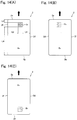
- the card 2 in a case that a card 2 is inserted into the insertion port in a correct posture, the card 2 is normally inserted from the one end 2e (in other words, in a direction shown by the arrow in Fig. 14(A) ) in a state that the front face 2a is directed upward.
- the magnetic body sensor is disposed at a position where an external connection terminal 2c of an IC card inserted into the insertion port in a correct posture is passed.
- the IC card reader described in Patent Literature 1 when a card 2 is inserted from the other end 2g side in a state that the rear face 2b is directed upward (in other words, in a direction shown by the arrow in Fig. 14(C) ), the external connection terminal 2c of the card 2 may be passed through the position where the magnetic body sensor is disposed.
- the IC card reader described in Patent Literature 1 includes a shutter and the distance "L4" largely differs from the distance "L3" and thus, even when a card 2 is inserted in a direction shown by the arrow in Fig.
- the other end 2g is abutted with the shutter before the external connection terminal 2c of the card 2 is passed through the position where the magnetic body sensor is disposed. Therefore, in the IC card reader, even when a card 2 is inserted in a direction shown by the arrow in Fig. 14(C) , it can be detected that a posture of an inserted card 2 is not correct based on a detected result of the magnetic body sensor. However, in the IC card reader, if the shutter is not provided, it is difficult to detect that a posture of the inserted card 2 is not correct when a card 2 is inserted in a direction shown by the arrow in Fig. 14(C) .
- the metal sensor provided in the card reader described in Patent Literature 2 is provided in the card reader described in Patent Literature 3, also in the card reader described in Patent Literature 3, it can be detected whether a card formed with an external connection terminal has been inserted into the insertion port or not (in other words, whether an IC card has been inserted into the insertion port or not) based on a detected result of the metal sensor.
- a card 2 is, for example, as shown in Fig. 15(A) , inserted from the one end face 2d side in a state that its front face 2a is directed upward (in other words, in a direction shown by the arrow in Fig. 15(A) ).
- a metal sensor is disposed at a position where an external connection terminal 2c of a card inserted into the insertion port in a correct posture is passed. Therefore, in the card reader, even when a card 2 is inserted from the other end face 2f side in a state that its rear face 2b is directed upward (in other words, in a direction shown by the arrow in Fig. 15(B) ), the external connection terminal of the card 2 is passed through the position where the metal sensor is disposed.
- An arrangement range of an external connection terminal 2c formed in an IC card 2 is specified in the international standard "ISO/IEC7816-2". Specifically, in the international standard "ISO/IEC7816-2", arrangement ranges of a first connection terminal 2p, a second connection terminal 2q, a third connection terminal 2r, a fourth connection terminal 2s, a fifth connection terminal 2t, a sixth connection terminal 2u, a seventh connection terminal 2v and an eighth connection terminal 2w which are formed as the external connection terminal 2c on the front face 2a of a card 2 are specified as shown in Fig. 16(B) . The arrangement ranges of the first through the eighth connection terminals 2p through 2w are specified to be the dimensions shown in Fig.
- FIG. 16(B) with the one end face 2e in a longitudinal direction of a card 2 and the one end face 2d in a short widthwise direction of the card 2 as references.
- the unit of the dimension shown in Fig. 16(B) is "mm" (millimeter) and, when the first through the eighth connection terminals 2p through 2w are formed at the dimension values in the drawing, the sizes of the first through the eighth connection terminals 2p through 2w become the smallest.
- a card 2 may be used which is formed with no fourth connection terminal 2s and no eighth connection terminal 2w.
- the distance "L1" does not differ from the distance "L2" largely as described above and thus, in the card reader described in Patent Literature 3, even in a case that a shutter is provided, when the other end face 2f of a card 2 inserted in a direction shown by the arrow in Fig. 15(B) is butted with the shutter, the external connection terminal 2c of the card 2 may be detected by the metal sensor. Therefore, in the card reader, when a card 2 is inserted in a direction shown by the arrow in Fig. 15(B) , there is a possibility that it is unable to determine whether the card 2 has been inserted in a correct posture or not based on a detected result of the metal sensor.
- signal levels of output signals of the metal sensor when the external connection terminal 2c is detected by the metal sensor are different from each other.
- a signal level of an output signal of the metal sensor when an external connection terminal 2c is detected by the metal sensor in a case that a card 2 is inserted in a state that its front face 2a is directed upward is higher than a signal level of an output signal of the metal sensor when an external connection terminal 2c is detected by the metal sensor in a case that a card 2 is inserted in a state that its rear face 2b is directed upward.
- the present inventors have found that there are some cards (hereinafter, referred to as a "low reactive card”) on the market whose signal level of an output signal of the metal sensor when an external connection terminal 2c is detected by the metal sensor is lower than that of a card commonly available on the market even in a case that the card 2 is inserted in a state that its front face 2a is directed upward.
- a low reactive card there are some cards (hereinafter, referred to as a "low reactive card”) on the market whose signal level of an output signal of the metal sensor when an external connection terminal 2c is detected by the metal sensor is lower than that of a card commonly available on the market even in a case that the card 2 is inserted in a state that its front face 2a is directed upward.
- the present inventors have examined and found that, since low reactive cards have been available on the market, it is difficult to appropriately set a threshold value for an output signal of the metal sensor and thus, there is a possibility that it is unable to determine whether a card 2 has been inserted in a correct posture or not based on a detected result of the metal sensor.
- a first objective of the present invention is to provide a card reader in which an IC card in a substantially rectangular shape in conformity with the international standard or JIS standard is taken in its longitudinal direction and is processed, the card reader being capable of easily determining whether a posture of an inserted IC card is correct or not even when a shutter member for opening and closing a card passage where the IC card is passed is not provided. Further, an objective of the present invention is to provide a card reader in which an IC card in a substantially rectangular shape in conformity with the international standard or JIS standard is taken in its short widthwise direction and is processed, the card reader being capable of easily determining whether a posture of an inserted IC card is correct or not.
- a second objective of the present invention is to provide a card reader in which an IC card in a substantially rectangular shape in conformity with the international standard is taken in its short widthwise direction and is processed, the card reader being capable of appropriately detecting whether a card formed with an external connection terminal has been inserted into an insertion port or not based on a detected result of a metal detection mechanism in a case that the size of the external connection terminal is the smallest and, even when the sensibility of the metal detection mechanism is lowered.
- a third objective of the present invention is to provide a card reader in which an IC card in a substantially rectangular shape in conformity with the international standard is taken in its short widthwise direction and is processed, the card reader being capable of appropriately determining whether a card has been inserted into an insertion port in a correct posture or not.
- an objective of the present invention is to provide a control method for a card reader in which an IC card in a substantially rectangular shape in conformity with the international standard is taken in its short widthwise direction and is processed, the control method being capable of appropriately determining whether a card has been inserted into an insertion port in a correct posture or not.
- the disclosure provides a card reader including an insertion port into which a card incorporated with an IC chip is inserted, a metal detection mechanism structured to detect an external connection terminal of the IC chip provided in the card, and a tip end detection mechanism structured to detect a tip end in an inserting direction of the card inserted into the insertion port.
- the metal detection mechanism and the tip end detection mechanism are disposed so that, when the tip end detection mechanism detects the tip end in the inserting direction of the card inserted into the insertion port in a correct posture, the metal detection mechanism detects the external connection terminal.
- the card reader includes, for example, a control section into which an output signal of the metal detection mechanism and an output signal of the tip end detection mechanism are inputted, and the control section determines whether the card has been inserted into the insertion port in a correct posture or not based on the output signal of the metal detection mechanism when the tip end detection mechanism detects the tip end of the card in the inserting direction.
- the metal detection mechanism structured to detect an external connection terminal and the tip end detection mechanism structured to detect a tip end of the card in an inserting direction are disposed at positions so that, when the tip end detection mechanism detects the tip end in the inserting direction of the card inserted in a correct posture, the metal detection mechanism detects the external connection terminal.
- the card reader is a card reader in which a substantially rectangular-shaped IC card in conformity with the international standard or JIS standard is taken into in its longitudinal direction and processed, even when a shutter member for opening and closing a card passage where the card is passed is not provided, it can be easily determined whether a posture of the inserted card is correct or not based on an output signal of the metal detection mechanism when the tip end detection mechanism detects a tip end of the card in the inserting direction.
- the card reader is a card reader in which a substantially rectangular-shaped IC card in conformity with the international standard or JIS standard is taken into in its short widthwise direction and processed, it can be easily determined whether a posture of the inserted card is correct or not based on an output signal of the metal detection mechanism when the tip end detection mechanism detects a tip end of the card in the inserting direction.
- the card reader in accordance with the present disclosure, for example, a card formed in a substantially rectangular shape is taken into in a short widthwise direction of the card and is processed.
- the card reader includes a width detection mechanism structured to detect both end parts of a card in a width direction which is perpendicular to a thickness direction and the inserting direction of the card inserted into the insertion port. According to this structure, it can be easily determined by using the width detection mechanism whether a card is inserted in its short widthwise direction or inserted in its longitudinal direction. Further, according to this structure, it can be detected by using the width detection mechanism whether a foreign matter is inserted into the insertion port or a card is inserted.
- the card reader includes a control section into which an output signal of the metal detection mechanism, an output signal of the tip end detection mechanism and an output signal of the width detection mechanism are inputted.
- the width detection mechanism is disposed on an insertion port side relative to the tip end detection mechanism, and the control section determines whether the card has been inserted into the insertion port in a correct posture or not based on a difference between a signal level of an output signal of the metal detection mechanism when the width detection mechanism detects both end parts of the card and a signal level of an output signal of the metal detection mechanism when the tip end detection mechanism detects a tip end of the card in the inserting direction.
- the card reader includes a card passage where the card inserted into the insertion port is passed and a shutter member structured to open and close the card passage, and the shutter member is disposed on a rear side of the card reader relative to the tip end detection mechanism.
- a card inserted in its longitudinal direction can be prevented from being entered to a rear side of the card reader by the shutter member.
- a foreign matter inserted into the insertion port can be prevented from being entered to a rear side of the card reader by the shutter member.
- the metal detection mechanism is a magnetic type sensor, which includes an excitation coil, a detection coil, and a core which is formed of magnetic material and around which the excitation coil and the detection coil are wound
- the tip end detection mechanism is an optical type sensor which includes a light emitting element and a light receiving element structured to receive light from the light emitting element.
- a distance in the inserting direction between the magnetic type sensor and the optical type sensor is longer than a distance between the tip end of the card inserted in a correct posture and the external connection terminal and is shorter than a length which is a total sum of the distance between the tip end of the card and the external connection terminal and a length of the external connection terminal in a short widthwise direction of the card.
- the present disclosure provides a card reader for use with a card which is incorporated with an IC chip and formed in a substantially rectangular shape, the card being taken into in its short widthwise direction to be performed with data communication.
- the card reader includes a card insertion part which is formed with an insertion port into which the card is inserted, a metal detection mechanism which is provided in the card insertion part and is structured to detect an external connection terminal of the IC chip formed on a front face of the card, and a card passage which is formed in the card insertion part for passing the card.
- the metal detection mechanism is a magnetic type sensor which includes a core made of magnetic material and an excitation coil and a detection coil which are wound around the core with an axial center of the core as a winding center.
- a direction perpendicular to a thickness direction and an inserting direction of the card inserted into the insertion port is referred to as a first direction
- one end face of the card in a longitudinal direction of the card is referred to as a first card reference end face
- one end face of the card in a short widthwise direction of the card is referred to as a second card reference end face
- one end of the card passage in the first direction is formed to be a reference surface where the first card reference end face is contacted when a normal card is inserted into the insertion port in a correct posture without inclination
- a distance in the first direction between the reference surface and the axial center of the core is set to be 10.25mm or more and 12.25mm or less, or set to be 17.87mm or more and 19.87mm or less.
- the metal detection mechanism is a magnetic type sensor which includes a core and an excitation coil and a detection coil wound around the core with an axial center of the core as a winding center, and one end of the card passage in the first direction is formed to be a reference surface where the first card reference end face is contacted when a normal card is inserted into the insertion port in a correct posture without inclination.
- a distance in the first direction between the reference surface and the axial center of the core is set to be 10.25mm or more and 12.25mm or less, or set to be 17.87mm or more and 19.87mm or less.
- an external connection terminal of the card is capable of passing an extended line of the axial center of the core.
- the first through the fourth connection terminals 2p through 2s or the fifth through the eighth connection terminals 2t through 2w are capable of passing the extended line of the axial center of the core.
- the present disclosure in a case that the sizes of the first through the eighth connection terminals 2p through 2w are the smallest, even when sensibility of the metal detection mechanism is lowered, the first through the fourth connection terminals 2p through 2s or the fifth through the eighth connection terminals 2t through 2w can be detected appropriately by the metal detection mechanism.
- the size of an external connection terminal in a case that the size of an external connection terminal is the smallest, even when sensibility of the metal detection mechanism is lowered, it can be appropriately detected whether a card formed with an external connection terminal is inserted into the insertion port or not based on a detected result of the metal detection mechanism.
- a distance between the tip end detection mechanism and the metal detection mechanism is set in a range which is longer than a distance ("L1" in Fig. 14(A) ) between a tip end of the card inserted in a correct posture and the external connection terminal and is shorter than a total length of the distance "L1" and a length in the short widthwise direction of the external connection terminal 2c.
- a width of the insertion port in the first direction is wider than a width in the longitudinal direction of the card
- the card insertion part includes a tip end detection mechanism structured to detect a tip end in the inserting direction of the card inserted into the insertion port, the tip end detection mechanism is disposed on a rear side relative to the metal detection mechanism in the inserting direction and, in a case that a normal card is inserted into the insertion port in a correct posture, the external connection terminal is detected by the metal detection mechanism before the second card reference end face disposed on a rear side in the inserting direction is detected by the tip end detection mechanism, and a distance between the reference surface and the axial center of the core in the first direction is set to be 17.87mm or more and 19.87mm or less.
- a width of the insertion port in the first direction is set to be wider than a width in the longitudinal direction of the card and thus a card is easily inserted into the insertion port.
- a width of the insertion port in the first direction is set to be wider than a width in the longitudinal direction of a card and thus the card inserted into the insertion port is easily inclined.
- the card is formed with a first connection terminal, a second connection terminal, a third connection terminal, a fifth connection terminal, a sixth connection terminal and a seventh connection terminal as the external connection terminal
- the first connection terminal, the second connection terminal and the third connection terminal are disposed from the second card reference end face in this order in the short widthwise direction of the card and are disposed at the same positions as each other in the longitudinal direction of the card
- the fifth connection terminal is disposed at the same position as the first connection terminal in the short widthwise direction of the card
- the sixth connection terminal is disposed at the same position as the second connection terminal in the short widthwise direction of the card
- the seventh connection terminal is disposed at the same position as the third connection terminal in the short widthwise direction of the card
- the fifth connection terminal, the sixth connection terminal and the seventh connection terminal are disposed at the same position as each other in the longitudinal direction of the card and are disposed at separated positions from the first card reference end face relative to the first connection terminal, the second connection terminal and the third connection terminal and, in a
- the tip end detection mechanism in a case that a normal card is inserted into the insertion port in a correct posture without inclination, in comparison with a case that the axial center of the core and the fifth connection terminal are overlapped with each other in a thickness direction of the card when the second card reference end face (tip end of the card) is detected by the tip end detection mechanism, it can be detected whether the card formed with the external connection terminal has been inserted into the insertion port or not by the metal detection mechanism at an earlier timing before a rear end face of the card (tip end of the card) is detected by the tip end detection mechanism. Therefore, predetermined processing in the card reader can be performed speedily after a rear end face of a card is detected by the tip end detection mechanism.
- a distance in the inserting direction of the card between the eighth connection terminal 2w and the axial center of the core when the card 2 is inserted in the direction shown by the arrow in Fig. 15(B) and the other end face 2f of the card 2 is detected by the tip end detection mechanism can be made longer. Therefore, in a case that a card 2 is inserted in a direction shown by the arrow in Fig.
- the present disclosure provides a card reader for use with a card which is incorporated with an IC chip and formed in a substantially rectangular shape, the card being taken into in its short widthwise direction to be performed with data communication.
- the card reader includes a card insertion part which is formed with an insertion port into which the card is inserted, and a control section structured to control the card reader.
- the card insertion part includes a metal detection mechanism structured to detect an external connection terminal of the IC chip formed on a front face of the card, and a tip end detection mechanism structured to detect a tip end of the card in an inserting direction of the card inserted into the insertion port.
- the metal detection mechanism is disposed at a position where the external connection terminal of the normal card inserted in a correct posture is passed in a card width direction perpendicular to a thickness direction and the inserting direction of the card inserted into the insertion port.
- the metal detection mechanism and the tip end detection mechanism are connected with the control section and are disposed so that, when the normal card is inserted into the insertion port in a correct posture, the metal detection mechanism detects the external connection terminal before the tip end detection mechanism detects the tip end of the card.
- a distance between one end face of the card in the short widthwise direction of the card and one end of the external connection terminal in the short widthwise direction of the card is shorter than a distance between the other end face of the card in the short widthwise direction of the card and the other end of the external connection terminal in the short widthwise direction of the card.
- the control section acquires a metal detection signal value based on an output signal of the metal detection mechanism at a predetermined cycle over at least a part of a time period until the tip end of the card is detected by the tip end detection mechanism and calculates an integrated value by integrating at least a part of a plurality of acquired metal detection signal values, and thereby the control section determines whether the normal card has been inserted into the insertion port in a correct posture or not based on the integrated value.
- the present disclosure provides a control method for a card reader for use with a card which is incorporated with an IC chip and formed in a substantially rectangular shape.
- the card reader includes a card insertion part formed with an insertion port into which the card is inserted in its short widthwise direction, and the card insertion part includes a metal detection mechanism structured to detect an external connection terminal of the IC chip formed on a front face of the card, and a tip end detection mechanism structured to detect a tip end of the card in an inserting direction of the card inserted into the insertion port.
- the metal detection mechanism is disposed at a position where the external connection terminal of the normal card inserted in a correct posture is passed in a card width direction perpendicular to a thickness direction and the inserting direction of the card inserted into the insertion port.
- the metal detection mechanism and the tip end detection mechanism are disposed so that, when the normal card is inserted into the insertion port in a correct posture, the metal detection mechanism detects the external connection terminal before the tip end detection mechanism detects the tip end of the card.
- a distance between one end face of the card in the short widthwise direction of the card and one end of the external connection terminal in the short widthwise direction of the card is shorter than a distance between the other end face of the card in the short widthwise direction of the card and the other end of the external connection terminal in the short widthwise direction of the card.
- the control method includes acquiring a metal detection signal value based on an output signal of the metal detection mechanism at a predetermined cycle over at least a part of a time period until the tip end of the card is detected by the tip end detection mechanism, calculating an integrated value by integrating at least a part of a plurality of acquired metal detection signal values, and determining whether the normal card has been inserted into the insertion port in a correct posture or not based on the integrated value.
- a metal detection signal value based on an output signal of the metal detection mechanism is acquired at a predetermined cycle over at least a part of a time period until the tip end of the card is detected by the tip end detection mechanism and an integrated value is calculated by integrating at least a part of a plurality of acquired metal detection signal values.
- a difference can be increased between an integrated value calculated by integrating at least a part of a plurality of metal detection signal values acquired at a predetermined cycle in a case that a card is inserted in a state that its front face is directed upward and an integrated value calculated by integrating at least a part of a plurality of metal detection signal values acquired at a predetermined cycle in a case that the card is inserted in a state that its rear face is directed upward. Accordingly, in the present disclosure, it can be appropriately determined whether a card has been inserted into the insertion port in a correct posture or not based on the integrated value.
- a distance between one end face of the card in a short widthwise direction of the card and one end of the external connection terminal in the short widthwise direction of the card is shorter than a distance between the other end face of the card in the short widthwise direction of the card and the other end of the external connection terminal in the short widthwise direction of the card.
- a metal detection signal value based on an output signal of the metal detection mechanism is acquired at a predetermined cycle over at least a part of a time period until the tip end of the card is detected by the tip end detection mechanism and an integrated value is calculated by integrating at least a part of a plurality of acquired metal detection signal values.
- the present disclosure even when a difference between a signal level of an output signal of the metal detection mechanism when an external connection terminal of a low reactive card inserted in a correct posture is detected by the metal detection mechanism and a signal level of an output signal of the metal detection mechanism when an external connection terminal of a card commonly available on the market which is inserted in a state that its rear face is directed upward is detected by the metal detection mechanism is small, a difference can be made clear between the integrated value in a case that a low reactive card is inserted in a correct posture and the integrated value in a case that a card commonly available on the market is inserted in a state that its rear face is directed upward. Accordingly, in the present disclosure, even when a low reactive card is inserted into the insertion port, it can be appropriately determined whether a card has been inserted into the insertion port in a correct posture or not based on the integrated value.
- the card insertion part includes an insertion detection mechanism structured to detect the card inserted into the insertion port, the insertion detection mechanism is connected with the control section and is disposed so that, in a case that a normal card is inserted into the insertion port in a correct posture, the insertion detection mechanism detects the card having been inserted into the insertion port before the one end of the external connection terminal in the short widthwise direction of the card is reached to the metal detection mechanism, and the control section acquires a metal detection signal value at a predetermined cycle over at least a part of a time period as a detection time after the card inserted into the insertion port is detected by the insertion detection mechanism and until the tip end of the card is detected by the tip end detection mechanism.
- the control section stores a signal level of an output signal of the metal detection mechanism when the card inserted into the insertion port is detected by the insertion detection mechanism as a reference value, and the metal detection signal value is a difference between a signal level of an output signal of the metal detection mechanism acquired at the predetermined cycle and the reference value.
- a metal detection signal value can be acquired which eliminates influence of variation of external environment such as variation of ambient temperature of the card reader. Therefore, accuracy of an acquired metal detection signal value can be enhanced and accuracy of the integrated value can be enhanced. As a result, it can be further appropriately determined whether a card has been inserted into the insertion port in a correct posture or not.
- the card reader includes a card conveying mechanism structured to convey the card at a constant speed when the card inserted into the insertion port is detected by the insertion detection mechanism.
- a card conveying mechanism structured to convey the card at a constant speed when the card inserted into the insertion port is detected by the insertion detection mechanism.
- a first elapsed time is defined as a time period after the card inserted into the insertion port is detected by the insertion detection mechanism and until a predetermined time before the one end of the external connection terminal in the short widthwise direction of the card is reached to the metal detection mechanism and, in a case that the normal card is inserted into the insertion port from the other end face side in the short widthwise direction of the card so that the external connection terminal passes the metal detection mechanism and is conveyed by the card conveying mechanism, a second elapsed time is defined as a time period after the card inserted into the insertion port is detected by the insertion detection mechanism and until a predetermined time before the other end of the external connection terminal in the short widthwise direction of the card is reached to the metal detection mechanism.
- control section calculates the integrated value by integrating at least a part of a plurality of the metal detection signal values acquired in the detection time, the detection time being at least a part of a time period after the first elapsed time has elapsed from the time when the card inserted into the insertion port is detected by the insertion detection mechanism and until the second elapsed time has elapsed from the time when the card inserted into the insertion port is detected by the insertion detection mechanism.
- the metal detection signal values are integrated over a time period from the time before the external connection terminal is reached to the metal detection mechanism and until the time after the external connection terminal has been reached to the metal detection mechanism to calculate an integrated value. Further, in a case that a card is inserted from the other end face in the short widthwise direction of the card so that its external connection terminal passes the metal detection mechanism, the metal detection signal values before the external connection terminal is reached to the metal detection mechanism can be integrated to calculate an integrated value.
- a difference between the integrated value in a case that a card is inserted in a correct posture and the integrated value in a case that a card is inserted from the other end face in a short widthwise direction of the card so that its external connection terminal passes the metal detection mechanism can be made larger.
- it can be further appropriately determined whether a card has been inserted into the insertion port in a correct posture or not based on the integrated value.
- a difference can be made further clear between an integrated value in a case that a low reactive card is inserted in a correct posture and an integrated value in a case that a card commonly available on the market is inserted in a state that its rear face is directed upward.
- even when a low reactive card is inserted into the insertion port it can be further appropriately determined whether a card has been inserted into the insertion port in a correct posture or not based on the integrated value.
- a distance between the tip end detection mechanism and the metal detection mechanism may be set in a range which is longer than a distance between the tip end of the card inserted in a correct posture and the external connection terminal and is shorter than a total length of the distance and a length in the short widthwise direction of the external connection terminal.
- the detection time may be set in a time period with a time point when the tip end detection mechanism detects the tip end of the card as a reference time point so that the detection time starts before the tip end detection mechanism detects the tip end of the card when the normal card is inserted into the insertion port in a correct posture, and that the detection time ends before the external connection terminal is reached to the metal detection mechanism when the normal card is inserted into the insertion port from the other end face side in the short widthwise direction of the card so that the external connection terminal passes the metal detection mechanism.
- the card reader includes a card conveying mechanism structured to convey the card, when the insertion detection mechanism detects that the card is inserted into the insertion port, while the card conveying mechanism is activated to convey the card at a constant speed, the metal detection signal value based on the output signal of the metal detection mechanism is acquired at a predetermined cycle until the tip end of the card is detected by the tip end detection mechanism, and the integrated value obtained by integrating the metal detection signal values in the detection time is compared with a predetermined detection threshold value and thereby it is determined whether the normal card has been inserted into the insertion port in a correct posture or not.
- the present disclosure which attains the first objective, in the card reader in which a substantially rectangular-shaped IC card in conformity with the international standard or JIS standard is taken into in its longitudinal direction and processed, even when a shutter member for opening and closing a card passage where the card is passed is not provided, it can be easily determined whether a posture of the inserted card is correct or not. Further, according to the present disclosure, in the card reader in which a substantially rectangular-shaped IC card in conformity with the international standard or JIS standard is taken into in its short widthwise direction and processed, it can be easily determined whether a posture of the inserted card is correct or not.
- the present disclosure which attains the second objective, in the card reader in which a substantially rectangular-shaped IC card in conformity with the international standard is taken into in its short widthwise direction and processed, in a case that the size of an external connection terminal is the smallest, even when sensibility of the metal detection mechanism is lowered, it can be appropriately detected whether a card formed with an external connection terminal is inserted into the insertion port or not based on a detected result of the metal detection mechanism.
- the card reader in which a substantially rectangular-shaped IC card in conformity with the international standard is taken into in its short widthwise direction and processed it can be appropriately determined whether a card is inserted into the insertion port in a correct posture or not.
- a control method for a card reader in which a substantially rectangular-shaped IC card in conformity with the international standard is taken into in its short widthwise direction and processed it can be appropriately determined whether a card is inserted into the insertion port in a correct posture or not.
- a card reader for attaining the first objective of the present disclosure will be described below.
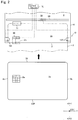
- Fig. 1 is a perspective view showing a card reader 1 in accordance with an embodiment of the present disclosure.
- a card reader 1 in this embodiment is a device for performing at least one of reading of data recorded in a card 2 and recording of data to a card 2 and is mounted for use on a predetermined host device such as an ATM (Automated Teller Machine).
- the card reader 1 includes a card insertion part 4 formed with an insertion port 3 into which a card 2 is inserted. Further, an inside of the card reader 1 is formed with a card passage 5 (see Fig. 2 ) where a card 2 inserted into the insertion port 3 is passed.
- the card passage 5 is formed so as to be connected with the insertion port 3. Further, the card reader 1 includes a card conveying mechanism structured to convey a card 2 in the card passage 5.
- the card 2 is made of vinyl chloride and its thickness is about 0.7-0.8mm.
- the card 2 in this embodiment is a contact type IC card with a magnetic stripe in conformity with the international standard (for example, ISO/IEC 7811) or JIS standard (for example, JISX 6302) and is formed in a substantially rectangular shape whose four corners are rounded.
- a rear face 2b of the card 2 is formed with a magnetic stripe (not shown) in which magnetic data are recorded.
- the card 2 is incorporated with an IC chip not shown and, as described above (in other words, as described with reference to Fig. 14(A) ), a front face 2a of the card 2 is formed with an external connection terminal 2c.
- an external connection terminal 2c is formed at a predetermined position with one end 2d in a short widthwise direction of the card 2 and one end 2e in a longitudinal direction of the card 2 as references.
- a distance "L1" between the one end 2d and the external connection terminal 2c and a distance “L2” between the other end 2f in a short widthwise direction of the card 2 and the external connection terminal 2c are different from each other
- a distance "L3” between the one end 2e and the external connection terminal 2c and a distance "L4" between the other end 2g in a longitudinal direction of the card 2 and the external connection terminal 2c are different from each other.
- a card 2 is conveyed in an "X" direction shown in Fig. 1 .
- a card 2 is inserted and taken in an "X1” direction and the card 2 is ejected in an "X2" direction.
- the "X" direction is a conveying direction of a card 2
- the "X1” direction is an inserting direction of a card 2
- the "X2" direction is an ejecting direction of a card 2.
- a card 2 is inserted into the card reader 1 so that the short widthwise direction of a card 2 is coincided with the "X" direction.
- the card 2 is conveyed in an inside of the card reader 1 so that the short widthwise direction of a card 2 is coincided with the "X" direction.
- a card 2 is taken into in a short widthwise direction of the card 2 and processed.
- a “Y” direction perpendicular to the "X” direction is a width direction of a card 2 inserted into the insertion port 3 and is a longitudinal direction of the card 2 taken into an inside of the card reader 1 in a correct posture.
- a "Z" direction in Fig. 1 perpendicular to the "X” direction and the "Y” direction is a thickness direction of a card 2 which is taken into an inside of the card reader 1.
- the card reader 1 is disposed so that the "Z" direction and a vertical direction are coincided with each other.
- the "X” direction is referred to as a “front and rear direction”
- the "Y” direction is referred to as a “right and left direction”
- the "Z” direction is as an "upper and lower direction”.
- an "X1" direction side is referred to as a “rear (back)” side
- an "X2" direction side is as a "front” side
- a "Z1” direction side is as an "upper” side
- a “Z2” direction side is as a “lower” side.
- the card reader 1 includes, in addition to the above-mentioned structures, a magnetic head structured to abut with a card 2 to perform reading of magnetic data recorded on the card 2 and recording magnetic data on the card 2, a head moving mechanism structured to move the magnetic head in a right and left direction perpendicular to the conveying direction of the card 2, an IC contact block structured to contact with the external connection terminal 2c of the card 2 to perform data communication, a contact block moving mechanism structured to move the IC contact block, and a positioning mechanism for positioning the card 2 having been taken into the inside of the card reader 1.
- the head moving mechanism includes a carriage on which the magnetic head is mounted, a guide shaft for guiding the carriage in the right and left direction, a lead screw structured to feed the carriage in the right and left direction, a cam plate for moving the magnetic head up and down, a turning prevention shaft for preventing turning of the carriage with the guide shaft as a center, and the like.
- the head moving mechanism moves the magnetic head in the right and left direction and moves the magnetic head up and down between a position where the magnetic head is capable of abutting with a magnetic stripe of a card 2 and a position where the magnetic head is retreated from the card passage 5.
- the head moving mechanism in this embodiment moves the magnetic head so as to retreat to a lower side with respect to the card passage 5.
- the IC contact block includes a plurality of IC contact springs structured to contact with an external connection terminal 2c of a card 2.
- the contact block moving mechanism moves the IC contact block between a position where the IC contact springs are capable of contacting with the external connection terminal and a position where the IC contact springs are retreated from the card passage 5.
- the contact block moving mechanism in this embodiment moves the IC contact springs so as to retreat to an upper side with respect to the card passage 5.
- the positioning mechanism includes a positioning member with which a rear end of a card 2 having been taken into an inside of the card reader 1 is abutted, and the like. The positioning mechanism positions a card 2 when the magnetic head and the IC contact block performs reading and recording of data.
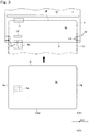
- Figs. 2 and 3 are explanatory views showing a schematic structure of the card insertion part 4 shown in Fig. 1 in accordance with a first embodiment.
- the card insertion part 4 structures a front face side portion of the card reader 1.
- the card insertion part 4 includes a metal detection mechanism 10 structured to detect an external connection terminal 2c of a card 2, a tip end detection mechanism 11 structured to detect a rear end of the card 2 inserted into the insertion port 3 (in other words, a tip end of the card 2 in an inserting direction), a width detection mechanism 12 structured to detect both end parts in a width direction of the card 2 ("Y" direction), and a shutter member 13 structured to open and close the card passage 5.
- the metal detection mechanism 10 is a magnetic type sensor including an excitation coil, a detection coil, and a core which is formed of magnetic material and around which the excitation coil and the detection coil are wound.
- a magnetic type sensor having a structure shown in Fig. 6 which will be described below may be used.
- the metal detection mechanism 10 is disposed on a front side relative to the tip end detection mechanism 11 in the front and rear direction.
- the metal detection mechanism 10 i.e., an opposed face of the core to a card 2 is disposed at a position in the right and left direction where an external connection terminal 2c of a card 2 inserted in a correct posture is passed (in other words, a posture where reading and recording of magnetic data by the magnetic head can be performed and reading and recording of data by the IC contact block can be performed (in other words, processing of the card 2 in the card reader 1 can be performed)).
- a case that a card 2 is inserted into the insertion port 3 from one end 2d side in a short widthwise direction of the card 2 in a state that its front face 2a is directed upward is a case that the card 2 is inserted in a correct posture. Therefore, when a card 2 is inserted into the insertion port 3 from the one end 2d side in a state that its front face 2a is directed upward, an external connection terminal 2c of the card 2 is detected by the metal detection mechanism 10.
- the tip end detection mechanism 11 is an optical sensor which includes a light emitting element and a light receiving element which receives light from the light emitting element.
- the tip end detection mechanism 11 in this embodiment is a transmission type optical sensor and the light emitting element and the light receiving element are disposed so as to interpose the card passage 5 in the upper and lower direction.
- the tip end detection mechanism 11 is disposed on a rear side relative to the metal detection mechanism 10 in the front and rear direction.
- the tip end detection mechanism 11 may utilize a reflection type optical sensor.
- the metal detection mechanism 10 and the tip end detection mechanism 11 are disposed at positions where the metal detection mechanism 10 detects an external connection terminal 2c when the tip end detection mechanism 11 detects a rear end (tip end) of a card 2 inserted into the insertion port 3 in a correct posture.
- a distance between the metal detection mechanism 10 and the tip end detection mechanism 11 in the front and rear direction is set to be substantially equal to a distance between a rear end of a card 2 inserted into the insertion port 3 in a correct posture and its external connection terminal 2c.
- a distance between the metal detection mechanism 10 and the tip end detection mechanism 11 is set so that, when a rear end (tip end) of a card 2 inserted into the insertion port 3 in a correct posture is reached to a detection position of the tip end detection mechanism 11, the metal detection mechanism 10 is located above the external connection terminal 2c.
- a distance between a detection position of the metal detection mechanism 10 and a detection position of the tip end detection mechanism 11 is set in a range which is longer than the length "L1" in Fig. 14A but shorter than the sum of the length "L1" and a length in a short widthwise direction of the external connection terminal 2c (length between the "L1" and the "L2").
- the metal detection mechanism 10 when a rear end of a card 2 is reached to a detection position of the tip end detection mechanism 11 and thereby its signal is outputted to a control section 70, the metal detection mechanism 10 is located at a position where the metal detection mechanism 10 faces the first connection terminal 2p and the fifth connection terminal 2t of the external connection terminal 2c shown in Figs. 16(A) and 16(B) .
- the metal detection mechanism 10 may be located above any connection terminal of the external connection terminal 2c.
- the metal detection mechanism 10 is disposed at a position where the metal detection mechanism 10 does not detect the external connection terminal 2c located on the rear face side.
- the width detection mechanism 12 is disposed on a front side relative to the tip end detection mechanism 11 in the front and rear direction.
- the width detection mechanism 12 includes two detection levers 120, which are disposed on both end sides in the right and left direction of the card insertion part 4 and are capable of protruding to and retreating from the card passage 5, and two optical or mechanical type sensors which detect respective movements of the two detection levers 120.
- parts of the detection levers 120 are disposed in an inside of the card passage 5.
- the shutter member 13 is disposed on a rear side relative to the tip end detection mechanism 11 in the front and rear direction. Specifically, the shutter member 13 is disposed at a rear end of the card insertion part 4.
- the shutter member 13 is connected with a drive mechanism for the shutter member 13 having a solenoid and the like and the shutter member 13 is movable between a closing position where the shutter member 13 is located so as to close the card passage 5 and an open position where the shutter member 13 is retreated to a lower side with respect to the card passage 5 to open the card passage 5.
- the metal detection mechanism 10, the tip end detection mechanism 11 and the width detection mechanism 12 are connected with a control section 70 of the card reader 1.
- An output signal of the metal detection mechanism 10, an output signal of the tip end detection mechanism 11 and an output signal of the width detection mechanism 12 are inputted to the control section 70.
- the control section 70 determines whether a card 2 has been inserted into the insertion port 3 in a correct posture or not based on an output signal of the metal detection mechanism 10, an output signal of the tip end detection mechanism 11 and an output signal of the width detection mechanism 12.
- the control section 70 determines whether a card 2 is inserted into the insertion port 3 so that a short widthwise direction of the card 2 is coincided with the front and rear direction or not based on an output signal of the width detection mechanism 12. Further, in this embodiment, in a case that a card 2 is inserted into the insertion port 3 so that a short widthwise direction of the card 2 is coincided with the front and rear direction and, in addition, the card 2 is inserted into the insertion port 3 from the one end 2d side in a state that its front face 2a is directed upward (in other words, in a case that a card 2 is inserted into the insertion port 3 in a correct posture), as shown in Fig.
- the control section 70 determines whether the card 2 inserted into the insertion port 3 so that its short widthwise direction is coincided with the front and rear direction is inserted into the insertion port 3 in a correct posture or not based on an output signal of the metal detection mechanism 10 when the tip end detection mechanism 11 detects a rear end of a card 2. Specifically, the control section 70 acquires a signal level of an output signal of the metal detection mechanism 10 which does not face the external connection terminal 2c when the width detection mechanism 12 detects both end parts of the card 2 and a signal level of an output signal of the metal detection mechanism 10 when the tip end detection mechanism 11 detects a rear end of the card 2. Based on a difference of the two signal levels, the control section 70 determines whether the card 2 inserted into the insertion port 3 so that its short widthwise direction is coincided with the front and rear direction is inserted into the insertion port 3 in a correct posture or not.
- the shutter member 13 in a standby state before a card 2 is inserted into the insertion port 3, the shutter member 13 is located at a closing position and the card passage 5 is closed.
- the shutter member 13 is moved to an open position when it is detected that a card 2 is inserted into the insertion port 3 so that a short widthwise direction of the card 2 is coincided with the front and rear direction based on a detected result of the width detection mechanism 12 and, in addition, it is detected that the card 2 has been inserted into the insertion port 3 from the one end 2d side in a state that its front face 2a is directed upward based on a detected result of the metal detection mechanism 10.
- the shutter member 13 when it is detected that a card 2 has been inserted into the insertion port 3 in a correct posture, the shutter member 13 is moved to the open position.
- the card conveying mechanism conveys the card 2 to a rear side and reading and recording of magnetic data by the magnetic head are performed and reading and recording of data through the IC contact block are performed.
- the card reader 1 in this embodiment includes the width detection mechanism 12. Therefore, according to this embodiment, as described above, it can be easily determined whether a card 2 has been inserted into the insertion port 3 so that a short widthwise direction of the card 2 is coincided with the front and rear direction or not.
- the metal detection mechanism 10 and the tip end detection mechanism 11 are disposed at positions where the metal detection mechanism 10 detects an external connection terminal 2c of a card 2 (the metal detection mechanism 10 faces an external connection terminal 2c) when the tip end detection mechanism 11 detects a rear end (tip end) of the card 2 inserted into the insertion port 3 in a correct posture (when the rear end of the card 2 is reached to and detected by the tip end detection mechanism 11 and an detection signal is outputted).
- the card reader 1 in this embodiment includes the width detection mechanism 12. Therefore, it is capable of detecting whether a foreign matter has been inserted into the insertion port 3 or a card 2 has been inserted by using the width detection mechanism 12.
- the shutter member 13 which closes the card passage 5 in a standby state is moved to an open position when it is detected that a card 2 has been inserted into the insertion port 3 from the one end 2d side in a state that its front face 2a is directed upward. Therefore, according to this embodiment, a card 2 inserted into the insertion port 3 in an incorrect posture can be prevented from being conveyed to a rear side of the card reader 1. Further, in this embodiment, a foreign matter inserted into the insertion port 3 can be prevented from entering to a rear side of the card reader 1 by the shutter member 13.
- the card reader 1 includes the width detection mechanism 12.
- the card reader 1 may include no width detection mechanism 12.
- the tip end detection mechanism 11 detects a rear end of the card 2
- the metal detection mechanism 10 faces and detects the external connection terminal 2c.
- the tip end detection mechanism 11 detects a rear end of the card 2
- the metal detection mechanism 10 does not detect the external connection terminal 2c.
- the control section 70 determines whether a card 2 has been inserted into the insertion port 3 in a correct posture or not based on an output signal of the metal detection mechanism 10 when the tip end detection mechanism 11 detects a rear end of the card 2. Specifically, the control section 70 determines whether a card 2 has been inserted into the insertion port 3 in a correct posture or not based on an absolute value of a signal level of an output signal of the metal detection mechanism 10 when the tip end detection mechanism 11 detects a rear end of the card 2.
- the control section 70 may determine whether a card 2 has been inserted into the insertion port 3 in a correct posture or not based on an absolute value of a signal level of an output signal of the metal detection mechanism 10 when the tip end detection mechanism 11 detects a rear end of the card 2. In other words, it may be determined whether a card 2 has been inserted into the insertion port 3 in a correct posture or not without using the width detection mechanism 12.
- the tip end detection mechanism 11 is an optical type sensor but the tip end detection mechanism 11 may utilize a mechanical type sensor such as a micro switch. Further, the tip end detection mechanism 11 may be structured of a lever member, which is structured to be contacted with and moved by a card 2, and an optical or mechanical type sensor which detects movement of the lever member. Further, in the embodiment described above, the width detection mechanism 12 is structured of the detection lever 120 and a sensor which detects movement of the detection lever 120. However, the width detection mechanism 12 may be structured of an optical or mechanical type sensor which directly detects a card 2
- the card reader 1 is a card reader in which a card 2 in a substantially rectangular shape in conformity with the international standard or JIS standard is taken into in its short widthwise direction and is processed.
- the card reader to which the present disclosure is applied may be a card reader in which a card 2 in a substantially rectangular shape in conformity with the international standard or JIS standard is taken into in its longitudinal direction and is processed. In this case, even when the shutter member 13 structured to open and close the card passage 5 is not provided, it can be determined whether a posture of an inserted card 2 is correct or not based on an output signal of the metal detection mechanism 10 when the tip end detection mechanism 11 detects a rear end of the card 2.
- a second embodiment for solving the second objective of the present disclosure will be described below.
- a basic structure of a card reader in this embodiment is substantially the same as the card reader 1 shown in Fig. 1 and is provided with similar functions and thus the same reference signs are used in the same structures and their detailed descriptions are omitted.
- the card 2 is made of vinyl chloride and its thickness is about 0.7-0.8mm.
- a rear face 2b of the card 2 is formed with a magnetic stripe (not shown) in which magnetic data are recorded.
- the card 2 in this embodiment is a card in conformity with the "ISO/IEC 7816-2" and is formed in a substantially rectangular shape whose four corners are rounded. Further, the card 2 is incorporated with an IC chip not shown and, as shown in Fig. 16(A) , a front face 2a of the card 2 is formed with an external connection terminal 2c of the IC chip.
- an arrangement range of the first through the eighth connection terminals 2p through 2w is specified in the international standard "ISO/IEC7816-2" and the arrangement range of the first through the eighth connection terminals 2p through 2w are specified in dimensions shown in Fig. 16(B) with the one end face 2e in a longitudinal direction of the card 2 and the one end face 2d in a short widthwise direction of the card 2 as the references.
- the first through the eighth connection terminals 2p through 2w are formed with dimension values shown in Fig. 16(B) and, in this case, the sizes of the first through the eighth connection terminals 2p through 2w are the smallest.
- the external connection terminal 2c is structured of a first connection terminal 2p, a second connection terminal 2q, a third connection terminal 2r, a fourth connection terminal 2s, a fifth connection terminal 2t, a sixth connection terminal 2u, a seventh connection terminal 2v and an eighth connection terminal 2w.
- the first through the fourth connection terminals 2p through 2s are, as shown in Fig. 16(A) and 16(B) , disposed in this order from the one end face 2d side in a short widthwise direction of the card 2 and disposed at the same positions as each other in a longitudinal direction of the card 2.
- the fifth connection terminal 2t is disposed at the same position as the first connection terminal 2p
- the sixth connection terminal 2u is disposed at the same position as the second connection terminal 2q
- the seventh connection terminal 2v is disposed at the same position as the third connection terminal 2r
- the eighth connection terminal 2w is disposed at the same position as the fourth connection terminal 2s.
- the fifth through the eighth connection terminals 2t through 2w are disposed at the same positions as each other in a longitudinal direction of the card 2 and are disposed at separated positions from the one end face 2e relative to the first through the fourth connection terminals 2p through 2s.
- the one end face 2e in this embodiment is a first card reference end face which is one end face of a card 2 in a longitudinal direction of the card 2, and the one end face 2d is a second card reference end face which is one end face of a card 2 in a short widthwise direction of the card 2.
- a case that a card 2 is inserted into the insertion port 3 from the one end face 2d side in a short widthwise direction of the card 2 in a state that its front face 2a is directed upward is a case that a card 2 is inserted into the insertion port 3 in a correct posture.
- the first through the fourth connection terminals 2p through 2s and the fifth through the eighth connection terminals 2t through 2w of the external connection terminal 2c of the card 2 are arranged in two rows in an inserting direction of the card at a position near to the reference surface 5a of the card passage 5.
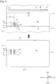
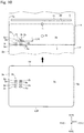
- Figs. 4 and 5 are explanatory views showing a schematic structure of the card insertion part 4 shown in Fig. 1 in accordance with the second embodiment.
- Fig. 6 is an explanatory view showing a structure of the metal detection mechanism 10 in Fig. 4 .
- the card insertion part 4 structures a front face side portion of the card reader 1.
- the card insertion part 4 includes, similarly to the first embodiment, a metal detection mechanism 10 structured to detect an external connection terminal 2c of a card 2, a tip end detection mechanism 11 structured to detect a rear end of the card 2 inserted into the insertion port 3 (in other words, a tip end of the card 2 in an inserting direction), and a shutter member 13 structured to open and close the card passage 5.
- a width of the insertion port 3 in the right and left direction is set to be wider than a width in a longitudinal direction of a card 2.
- a left end of the card passage 5 is formed as a reference surface 5a with which a left end face of a card 2 inserted into the insertion port 3 is contacted.
- one end of the card passage 5 in the right and left direction is structured as a reference surface 5a with which one end face in the right and left direction of a card 2 inserted into the insertion port 3 is contacted.
- the reference surface 5a is formed in parallel to the "Z-X" plane structured of the upper and lower direction and the front and rear direction.
- the reference surface 5a is a conveyance reference surface for a card 2 which is conveyed through the card passage 5.
- the card insertion part 4 is, for example, disposed with an urging member (not shown) such as a plate spring. A card 2 inserted into the insertion port 3 is urged to a left direction so that a left end face of the card 2 is contacted with the reference surface 5a by an urging force of the urging member.
- a case that a card 2 is inserted into the insertion port 3 from the one end face 2d side in a short widthwise direction of the card 2 in a state that its front face 2a is directed upward is a case that a card 2 is inserted into the insertion port 3 in a correct posture. Therefore, when a normal card 2 is inserted into the insertion port 3 in a correct posture without being inclined, its front face 2a is directed upward, its one end face 2d is disposed on a rear side, and its one end face 2e in a longitudinal direction of the card 2 is abutted with the reference surface 5a.
- the phrase that "a card 2 is inserted into the insertion port 3 in a correct posture” also includes a case that a card 2 is inserted into the insertion port 3 in a state that a short widthwise direction of the card 2 is inclined with respect to the front and rear direction.
- the phrase that "a card 2 is inserted into the insertion port 3 in a correct posture without being inclined” means that a card 2 is inserted into the insertion port 3 in a correct posture and in a state that a short widthwise direction of the card 2 is not inclined with respect to the front and rear direction.
- the tip end detection mechanism 11 is an optical sensor which includes a light emitting element and a light receiving element which receives light from the light emitting element.
- the tip end detection mechanism 11 in this embodiment is a transmission type optical sensor and the light emitting element and the light receiving element are disposed so as to interpose the card passage 5 in the upper and lower direction.
- the tip end detection mechanism 11 in this embodiment is structured similarly to the tip end detection mechanism 11 in the first embodiment and, in this embodiment, the tip end detection mechanism 11 is disposed at a center part of the card passage 5 and shown by the "o" (circle) mark.
- the tip end detection mechanism 11 is disposed on a rear side relative to the metal detection mechanism 10 in the front and rear direction.
- the tip end detection mechanism 11 may utilize a reflection type optical sensor.
- the metal detection mechanism 10 is, as shown in Fig. 6 , a magnetic type sensor which includes a core 15 formed of magnetic material and a pair of excitation coils 16 and 17 and a detection coil 18 which are wound around the core 15 with an axial center "CL" of the core 15 as a winding center.
- the core 15 is formed in a thin plate shape whose thickness direction is a direction perpendicular to the drawing in Fig. 6 .
- the core 15 is structured of a center core part 15a, which is disposed at a substantially center in an axial direction of the axial center "CL", a pair of axially end core parts 15b which are respectively disposed on both end sides of the center core part 15a in an axial direction of the axial center "CL”, and flange parts 15c which are disposed between the center core part 15a and the axially end core parts 15b.
- the excitation coils 16 and 17 are wound around a pair of the axially end core parts 15b.
- the detection coil 18 is wound around the center core part 15a.
- One end sides of the excitation coils 16 and 17 are connected with a variable resistor 20.
- the variable resistor 20 is connected with an AC power source 21.
- the other end sides of the excitation coils 16 and 17 are grounded.
- Both end parts of the detection coil 18 are connected with a detection circuit not shown.
- variation of a magnetic field generated by the excitation coils 16 and 17 is detected by the detection coil 18 and thereby an external connection terminal 2c of a card 2 is detected.
- the metal detection mechanism 10 is disposed on an upper side of the card passage 5. Further, the metal detection mechanism 10 is disposed so that an axial direction of the axial center "CL" of the core 15 and the upper and lower direction are coincided with each other and so that a lower end face of the axially end core part 15b is capable of facing a card 2. Further, in this embodiment, a distance "L" between the reference surface 5a and the axial center "CL" of the core 15 in the right and left direction is set not less than 17.87mm and not more than 19.87mm. In other words, the dimension of an external connection terminal 2c which is formed in a card used in this embodiment is set as shown in Fig.
- the metal detection mechanism 10 is disposed so that, when a normal card 2 is inserted into the insertion port 3 in a correct posture without inclination, the fifth through the eighth connection terminals 2t through 2w pass an extended line of the axial center "CL" of the core 15.
- a distance "L” between the reference surface 5a and the axial center "CL” is set to be 18.87mm.
- the metal detection mechanism 10 is disposed so that, when a normal card 2 is inserted into the insertion port 3 in a correct posture, an external connection terminal 2c of the card 2 is detected by the metal detection mechanism 10 before the one end face 2d of the card 2 is detected by the tip end detection mechanism 11.
- a distance between the tip end detection mechanism 11 and the metal detection mechanism 10 is set longer than a distance between a rear end of a card inserted in a correct posture and its external connection terminal but is set shorter than a length which is the sum of the above-mentioned distance and a length in a short widthwise direction of the external connection terminal 2c. Specifically, as shown in Fig.
- the metal detection mechanism 10 is disposed so that, in a case that a normal card 2 is inserted into the insertion port 3 in a correct posture without inclination, when the one end face 2d is detected by the tip end detection mechanism 11 (when a detection output by the tip end detection mechanism is varied), the axial center "CL" of the core 15 and the sixth connection terminal 2u are overlapped with each other in the upper and lower direction, in other words, the core 15 and the sixth connection terminal 2u are faced each other. Therefore, at least the fifth connection terminal 2t is detected by the metal detection mechanism 10 before the one end face 2d is detected by the tip end detection mechanism 11. In other words, a distance between the axial center "CL" of the core 15 and the tip end detection mechanism 11 in the front and rear direction is set to be substantially equal to a distance between the one end face 2d of a card 2 and its sixth connection terminal 2u.
- the eighth connection terminal 2w does not reach to a position where the metal detection mechanism 10 is disposed in the front and rear direction. Therefore, in the card reader 1 in this embodiment, it can be detected whether a normal card 2 is inserted into the insertion port 3 in a correct posture or not based on a detected result of the metal detection mechanism 10 when a rear end face of the card 2 is detected by the tip end detection mechanism 11.
- the shutter member 13 in a standby state before a card 2 is inserted into the insertion port 3, the shutter member 13 is located at a closing position and the card passage 5 is closed.
- the shutter member 13 is moved to an open position when it is detected that a normal card 2 has been inserted into the insertion port 3 in a correct posture based on detected results of the metal detection mechanism 10 and the tip end detection mechanism 11. Further, when it is detected that a card 2 has been inserted into the insertion port 3 in a correct posture, the card conveying mechanism conveys the card 2 to a rear side and reading and recording of magnetic data by the magnetic head are performed and reading and recording of data through the IC contact block are performed.
- the metal detection mechanism 10 when a normal card 2 is inserted into the insertion port 3 in a correct posture without inclination, the metal detection mechanism 10 is disposed so that the fifth through the eighth connection terminals 2t through 2w pass the extended line of the axial center "CL" of the core 15. Therefore, in this embodiment, in a case that the sizes of the first through the eighth connection terminals 2p through 2w are the smallest, even when sensibility of the metal detection mechanism 10 is lowered, the fifth through the eighth connection terminals 2t through 2w can be detected appropriately by the metal detection mechanism 10.
- an external connection terminal 2c of a card 2 is formed to be the smallest, even when sensibility of the metal detection mechanism 10 is lowered, it can be appropriately detected whether a card 2 formed with an external connection terminal is inserted into the insertion port 3 or not based on a detected result of the metal detection mechanism 10.
- the metal detection mechanism 10 is disposed so that, in a case that a normal card 2 is inserted into the insertion port 3 in a correct posture without inclination, when the one end face 2d is detected by the tip end detection mechanism 11, the axial center "CL" of the core 15 and the sixth connection terminal 2u are overlapped with each other in the upper and lower direction (the core 15 and the sixth connection terminal 2u are faced each other).
- the metal detection mechanism 10 in comparison with a case that the metal detection mechanism 10 is disposed so that, in a case that a normal card 2 is inserted into the insertion port 3 in a correct posture without inclination, when the one end face 2d is detected by the tip end detection mechanism 11, the axial center "CL" of the core 15 and the fifth connection terminal 2t are overlapped with each other in the upper and lower direction, it can be detected by the metal detection mechanism 10 whether a card 2 formed with an external connection terminal 2c has been inserted into the insertion port 3 or not at a further earlier timing before a rear end face (tip end) of the card 2 is detected by the tip end detection mechanism 11. Accordingly, in this embodiment, a predetermined processing in the card reader 1 can be performed quickly after a rear end face (tip end) of a card 2 is detected by the tip end detection mechanism 11.
- the metal detection mechanism 10 is disposed so that, in a case that a normal card 2 is inserted into the insertion port 3 in a correct posture without inclination, when the one end face 2d (tip end) is detected by the tip end detection mechanism 11, the axial center "CL" of the core 15 and the seventh connection terminal 2v are overlapped with each other in the upper and lower direction, a distance between the eighth connection terminal 2w and the axial center "CL" of the core 15a in the front and rear direction can be made longer when a card 2 is inserted in the direction shown by the arrow in Fig. 15(B) and its other end face 2f is detected by the tip end detection mechanism 11.
- the eighth connection terminal 2w is surely prevented from being detected by the metal detection mechanism 10 and, as a result, it can be further appropriately detected whether a card 2 has been inserted in a correct posture or not.
- a width of the insertion port 3 in the right and left direction is set to be wider than a width in a longitudinal direction of a card 2. Therefore, according to this embodiment, even when a card 2 is taken into the card reader 1 in its short widthwise direction, the card 2 is easily inserted into the insertion port 3.
- a distance “L” between the reference surface 5a and the axial center “CL” of the core 15 in the right and left direction is set to be not less than 17.87mm and not more than 19.87mm.
- a distance “L” between the reference surface 5a and the axial center “CL” may be set not less than 10.25mm and not more than 12.25mm.
- the metal detection mechanism 10 may be disposed so that, when a normal card 2 is inserted into the insertion port 3 in a correct posture without inclination, the first through the fourth connection terminals 2p through 2s pass the extended line of the axial center "CL" of the core 15 (see Fig.
- a distance "L" between the reference surface 5a and the axial center “CL” may be set to be 11.25mm.
- the metal detection mechanism 10 is, for example, disposed so that, in a case that a normal card 2 is inserted into the insertion port 3 in a correct posture without inclination, when one end face 2d is detected by the tip end detection mechanism 11, the axial center "CL" of the core 15 and the second connection terminal 2q are overlapped with each other in the upper and lower direction.
- the first through the fourth connection terminals 2p through 2s can be appropriately detected by the metal detection mechanism 10. Therefore, it can be appropriately detected whether a card 2 formed with an external connection terminal 2c has been inserted into the insertion port 3 or not based on a detected result of the metal detection mechanism 10.
- a width of the insertion port 3 in the right and left direction is set to be wider than a width in a longitudinal direction of a card 2 and thus the card 2 is easily inclined. Therefore, it is preferable that a distance "L" between the reference surface 5a and the axial center "CL" is not less than 17.87mm and not more than 19.87mm.
- a distance "L" between the reference surface 5a and the axial center "CL” is not less than 17.87mm and not more than 19.87mm.
- a distance "L” between the reference surface 5a and the axial center “CL” is set to be not less than 17.87mm and not more than 19.87mm (see Fig. 7(A) )
- a distance "L” between the reference surface 5a and the axial center “CL” is set not less than 10.25mm and not more than 12.25mm (see Fig. 7(B) )
- a predetermined processing in the card reader 1 can be performed quickly after a rear end face of a card 2 is detected by the tip end detection mechanism 11.
- a distance in the front and rear direction between the eighth connection terminal 2w and the axial center "CL" when a distance "L” between the reference surface 5a and the axial center “CL” is set not less than 17.87mm and not more than 19.87mm is longer than a distance in the front and rear direction between the fourth connection terminal 2s and the axial center "CL” when the distance "L” between the reference surface 5a and the axial center “CL” is set not less than 10.25mm and not more than 12.25mm.
- the metal detection mechanism 10 is disposed so that an axial direction of the axial center "CL" of the core 15 and the upper and lower direction are coincided with each other.
- the present disclosure is not limited to this embodiment.
- the metal detection mechanism 10 may be disposed so that the axial center "CL" of the core 15 is inclined with respect to the upper and lower direction when viewed in the right and left direction.
- the metal detection mechanism 10 is disposed so that, when the one end face 2d is detected by the tip end detection mechanism 11, an extended line of the axial center "CL” passes through the sixth connection terminal 2u (lower end face of the core 15 formed on the extended line of the axial center "CL" faces the sixth connection terminal 2u).
- the metal detection mechanism 10 is disposed so that, when the one end face 2d is detected by the tip end detection mechanism 11, the axial center "CL" of the core 15 and the sixth connection terminal 2u are overlapped with each other in the upper and lower direction.
- the present disclosure is not limited to this embodiment.
- the metal detection mechanism 10 may be disposed so that, in a case that a normal card 2 is inserted into the insertion port 3 in a correct posture without inclination, when the one end face 2d is detected by the tip end detection mechanism 11, the fifth connection terminal 2t, the seventh connection terminal 2v or the eighth connection terminal 2w is overlapped with the axial center "CL" of the core 15 in the upper and lower direction.
- the metal detection mechanism 10 includes a pair of the excitation coils 16 and 17.
- the metal detection mechanism 10 may include only one excitation coil.
- the tip end detection mechanism 11 is an optical type sensor.
- the tip end detection mechanism 11 may be a mechanical type sensor such as a micro switch.
- the tip end detection mechanism 11 may be structured of a lever member, which is capable of contacting with and moved by a card 2, and an optical or mechanical type sensor which detects movement of the lever member.
- a magnetic stripe is formed on a rear face 2b of a card 2 but no magnetic stripe may be formed on a rear face 2b of a card 2.
- the card reader 1 is a card conveyance type card reader having a card conveying mechanism but the card reader 1 may be a manual type card reader having no card conveying mechanism.
- the card reader 1 may be a so-called dip-type card reader.
- a third embodiment for attaining the third objective of the present disclosure will be described below.
- a basic structure of a card reader in this embodiment is substantially the same as the card reader 1 shown in Fig. 1 and is provided with similar functions and thus the same reference signs are used in the same structures and their detailed descriptions are omitted.
- a card same as the second embodiment is used in the third embodiment.
- Fig. 9 is a block diagram showing a control section 70 and structures relating to a taking-in operation of a card 2 in the card reader 1 shown in Fig. 1 .
- Figs. 10 through 12(B) are explanatory views showing a schematic structure of the card insertion part 4 shown in Fig. 1 in a third embodiment.
- a magnetic type sensor similar to the metal detection mechanism 10 shown in Fig. 6 may be used.
- the card insertion part 4 structures a front face side portion of the card reader 1.
- the card insertion part 4 includes an insertion detection mechanism 9 structured to detect a card 2 inserted into the insertion port 3, a metal detection mechanism 10 structured to detect an external connection terminal 2c of the card 2, a tip end detection mechanism 11 structured to detect a rear end of the card 2 inserted into the insertion port 3 (in other words, a tip end of the card 2 in an inserting direction), a shutter member 13 structured to open and close the card passage 5, and a shutter drive mechanism 14 structured to drive the shutter member 13.
- the insertion detection mechanism 9, the metal detection mechanism 10, the tip end detection mechanism 11 and the shutter drive mechanism 14 are connected with the control section 70.
- a width of the insertion port 3 in the right and left direction is set to be wider than a width in a longitudinal direction of a card 2.
- a left end of the card passage 5 is formed as a reference surface 5a with which a left end face of a card 2 inserted into the insertion port 3 is contacted.
- the reference surface 5a is a conveyance reference surface for a card 2 which is conveyed along the card passage 5.
- the card insertion part 4 is, for example, disposed with an urging member (not shown) such as a plate spring. A card 2 inserted into the insertion port 3 is urged to a left direction so that a left end face of the card 2 is contacted with the reference surface 5a by an urging force of the urging member.
- the insertion detection mechanism 9 is, for example, an optical sensor which includes a light emitting element and a light receiving element which receives light from the light emitting element.
- the insertion detection mechanism 9 is, for example, a transmission type optical sensor.
- the light emitting element and the light receiving element structuring the insertion detection mechanism 9 are disposed so as to interpose the card passage 5 in the upper and lower direction. When light emitted from the light emitting element to the light receiving element is intercepted by a rear end portion of a card 2 inserted into the insertion port 3, it is detected that a card 2 has been inserted into the insertion port 3
- the insertion detection mechanism 9 may be a reflection type optical sensor or may be a mechanical type sensor such as a micro switch. Further, the insertion detection mechanism 9 may include a so-called width detection mechanism which is disposed on both sides of the card passage 5 in the right and left direction for detecting both ends in a longitudinal direction of a card 2.
- the width detection mechanism is, for example, structured of lever members, which are respectively contacted with and moved by both end faces in the right and left direction of the card 2, and optical or mechanical type sensors which detect movement of the lever members.
- the tip end detection mechanism 11 is, for example, an optical type sensor which includes a light emitting element and a light receiving element which receives light from the light emitting element.
- the metal detection mechanism 10 is disposed on an upper side of the card passage 5. Further, the metal detection mechanism 10 is disposed so that an axial direction of the axial center "CL" of the core 15 and the upper and lower direction are coincided with each other. Further, similarly to the above-mentioned second embodiment, the metal detection mechanism 10 is disposed at a position in the right and left direction where an external connection terminal 2c of a normal card 2 inserted into the insertion port 3 in a correct posture is passed. In this embodiment, the metal detection mechanism 10 is disposed so that, when a normal card 2 is inserted into the insertion port 3 in a correct posture without inclination, the fifth through the eighth connection terminals 2t through 2w pass an extended line of the axial center "CL" of the core 15.
- the metal detection mechanism 10 and the tip end detection mechanism 11 are disposed so that, when a normal card 2 is inserted into the insertion port 3 in a correct posture, the metal detection mechanism 10 detects an external connection terminal 2c of the card 2 before the tip end detection mechanism 11 detects its one end face 2d.
- the metal detection mechanism 10 and the tip end detection mechanism 11 are disposed so that, in a case that a normal card 2 is inserted into the insertion port 3 in a correct posture without inclination, when the card 2 is reached to a detection position where the tip end detection mechanism 11 detects the one end face 2d, the axial center "CL" of the core 15 and the sixth connection terminal 2u are overlapped with each other in the upper and lower direction.
- a distance "L10" in the front and rear direction between a rear end of the fifth connection terminal 2t and the axial center "CL" of the core 15 when the tip end detection mechanism 11 detects the one end face 2d is 2.92mm (a rear end of the fifth connection terminal 2t, i.e., a tip end of the external connection terminal 2c has already passed the axial center "CL" of the core 15).
- a detection start time for the external connection terminal 2c by the metal detection mechanism 10 becomes the most delayed when the card 2 inserted into the insertion port 3 is moved to a rear side at a constant speed.
- a width of the insertion port 3 in the right and left direction is set to be wider than a width in a longitudinal direction of a card 2. Therefore, when a normal card 2 is inserted into the insertion port 3 in a correct posture, the card 2 may be inserted into the insertion port 3 in a state that a short widthwise direction of the card 2 is inclined with respect to the front and rear direction. In a case that a card 2 is inclined in a state shown in Fig.
- a normal card 2 commonly available on the market is inserted into the insertion port 3 from the other end face 2f side in a state that its rear face 2b is directed upward
- the card 2 is inserted into the insertion port 3 in a state that a short widthwise direction of the card 2 is inclined with respect to the front and rear direction.
- a card 2 is inclined in a state shown in Fig.
- a distance "L13" in the front and rear direction (see Fig. 12(B) ) between a rear end of the external connection terminal 2c and the axial center "CL" of the core 15 when the tip end detection mechanism 11 detects the other end face 2f is 0.561mm (even in this state, a tip end of the external connection terminal 2c does not reach to the position of the core 15).
- the insertion detection mechanism 9 and the metal detection mechanism 10 are disposed so that, in a case that a normal card 2 is inserted into the insertion port 3 in a correct posture, the insertion detection mechanism 9 detects the card 2 inserted into the insertion port 3 before a rear end of the external connection terminal 2c is reached to the metal detection mechanism 10 (specifically, the axial center "CL" of the core 15).
- the shutter member 13 is disposed on a rear side relative to the tip end detection mechanism 11 in the front and rear direction.
- a shutter drive mechanism 14 is connected with the shutter member 13.
- the shutter member 13 is movable between a closing position where the shutter member 13 is located on the card passage 5 to close the card passage 5 and an open position where the shutter member 13 is retreated to a lower side with respect to the card passage 5 to open the card passage 5.
- Fig. 13 is a flow chart showing a flow of a taking-in operation for a card 2 in the card reader 1 shown in Fig. 1 .
- the shutter member 13 In the card reader 1, in a standby state before a card 2 is inserted into the insertion port 3, the shutter member 13 is located at the closing position and the card passage 5 is closed. In the standby state, the card conveying mechanism 6 is stopped. Further, in the standby state, a voltage is applied to the excitation coils 16 and 17. In this state, when it is detected by the insertion detection mechanism 9 that a card 2 is inserted into the insertion port 3, a taking-in operation for the card 2 is started by the card reader 1.
- the control section 70 stores at this time a signal level of an output signal of the metal detection mechanism 10 as a reference value (step “S1").
- the control section 70 stores the reference value which is a signal level of an output signal of the metal detection mechanism 10 in a state that the metal detection mechanism 10 does not face the external connection terminal 2c.
- the control section 70 activates the card conveying mechanism 6 to convey the card 2 at a constant speed (step "S2").
- the card conveying mechanism 6 conveys the card 2 at a constant speed when it is detected by the insertion detection mechanism 9 that the card 2 is inserted into the insertion port 3.
- the card conveying mechanism 6 conveys the card 2 at 190mm/sec.
- the control section 70 judges whether a predetermined time has elapsed after the reference value is stored in the step "S1" or not (step “S3") and, when the predetermined time has elapsed, the control section 70 acquires a metal detection signal value based on an output signal of the metal detection mechanism 10 (step "S4"). Specifically, the control section 70 acquires a metal detection signal value in the step "S4" which is a difference (i.e., variation amount) between a signal level of an output signal of the metal detection mechanism 10 at this time point and the reference value acquired in the step "S1".
- the predetermined time in the step “S3" is 1 millisecond (msec). However, the predetermined time in the step “S3" may be longer than 1msec or may be shorter than 1msec.
- control section 70 judges whether the number of the metal sensing signal values stored in the control section 70 is not less than a predetermined number or not (step “S5").
- the control section 70 stores the latest metal detection signal value acquired in the step "S4" in the control section 70 (step “S6").
- step "S5" in a case that the number of the metal detection signal values stored in the control section 70 is not less than the predetermined number, the control section 70 erases the oldest metal detection signal value stored in the control section 70 (step “S7") and then, in the step "S6", the latest metal detection signal value acquired in the step "S4" is stored in the control section 70.
- the operation in which the number of the metal detection signal values is limited to a predetermined number is an operation for limiting a detection time by the metal detection mechanism 10 within a predetermined period.
- the detection time by the metal detection mechanism 10 is limited to a predetermined period.
- the time when the tip end detection mechanism 11 detects a rear end (the one end face 2d or the other end face 2f) of a card 2 is determined as a reference time point and a predetermined time period before the reference time point is determined as a detection time. Therefore, old metal sensing signal values are erased which are largely separated from the reference time point when the tip end detection mechanism 11 detects a rear end (the one end face 2d or the other end face 2f) of the card 2.
- the metal detection signal values within an effective time period determined as the detection time are integrated.
- the predetermined number in the step "S5" is 17. However, the predetermined number in the step "S5" may be not more than 16 or may be not less than 18.
- the control section 70 judges whether a rear end of the card 2 is detected by the tip end detection mechanism 11 or not (step “S8").
- the control section 70 judges whether a rear end of the card 2 is detected by the tip end detection mechanism 11 or not (step “S8").
- the control section 70 judges whether a predetermined time has elapsed or not after acquiring the metal detection signal value in the previous step "S4" and, when the predetermined time has elapsed, the step "S4" is executed.
- the control section 70 calculates an integrated value by integrating at least a part of a plurality of the metal detection signal values stored in the control section 70 (step “S9").
- a time period not less than 17msec has elapsed after it is detected by the insertion detection mechanism 9 that a card 2 is inserted into the insertion port 3 and until a rear end of the card 2 is detected by the tip end detection mechanism 11. Therefore, when a rear end of the card 2 is detected by the tip end detection mechanism 11, seventeen (17) metal detection signal values are stored in the control section 70.
- the control section 70 integrates twelve (12) metal detection signal values as an integrating range, which is from a metal detection signal value stored 5msec before the time when the rear end of the card 2 is detected by the tip end detection mechanism 11 to a metal detection signal value stored 17msec before, and the integrated value is calculated in the integrating range.
- the control section 70 judges whether the integrated value calculated in the step "S9" exceeds a predetermined detection threshold value or not (step “S10").
- the control section 70 judges that a normal card 2 has been inserted into the insertion port 3 in a correct posture and activates the shutter drive mechanism 14 to move the shutter member 13 to an open position, and the control section 70 takes the card 2 into an inside of the card reader 1 (step “S11").
- the card 2 having been taken into the inside is performed with reading and recording of magnetic data by a magnetic head and reading and recording of data by an IC contact block.
- the control section 70 judges that a non-normal card 2 has been inserted into the insertion port 3, or that a normal card 2 has been inserted into the insertion port 3 in an incorrect posture, and thus the control section 70 reversely rotates the card conveying mechanism 6 to eject the card 2 from the insertion port 3 (step "S12").
- the control section 70 acquires a metal detection signal value based on an output signal of the metal detection mechanism 10 at a cycle of 1msec after it is detected by the insertion detection mechanism 9 that the card 2 is inserted into the insertion port 3 until a rear end of the card 2 is detected by the tip end detection mechanism 11. Further, the control section 70 calculates an integrated value by integrating a part of the acquired plural metal detection signal values in the step "S9". In addition, in the step "S10", the control section 70 determines whether a normal card 2 has been inserted into the insertion port 3 in a correct posture or not based on the integrated value calculated in the step "S9".
- the card conveying mechanism 6 conveys a card 2 at a speed of 190mm/sec.
- the control section 70 integrates the metal detection signal values having been acquired from the time before a rear end of the external connection terminal 2c is reached to the metal detection mechanism 10 in the step "S9".
- the control section 7 finishes acquisition of a metal detection signal value before a rear end of an external connection terminal 2c is reached to the metal detection mechanism 10.
- a time period from the time when it is detected by the insertion detection mechanism 9 that the card 2 is inserted into the insertion port 3 and until a predetermined time before a rear end of the external connection terminal 2c is reached to the metal detection mechanism 10 is set to be a first elapsed time and, in a case that a normal card 2 is inserted into the insertion port 3 from the other end face 2f side in a state that its rear face 2b is directed upward and is conveyed by the card conveying mechanism 6, a time period from the time when it is detected by the insertion detection mechanism 9 that the card 2 is inserted into the insertion port 3 and until a predetermined time before a rear end of the external connection terminal 2c is reached to the metal detection mechanism 10 is set to be a second elapsed time.
- control section 70 calculates an integrated value by integrating a plurality of metal detection signal values acquired at least a part of a time period, which is after the first elapsed time has elapsed from the time when it is detected by the insertion detection mechanism 9 that the card 2 is inserted into the insertion port 3 and before the second elapsed time has elapsed from the time when it is detected by the insertion detection mechanism 9 that the card 2 is inserted into the insertion port 3.
- the control section 70 calculates an integrated value by integrating twelve (12) metal detection signal values as an integrating range, which is from a metal detection signal value stored 5msec before the time when a rear end of the card 2 is detected by the tip end detection mechanism 11 to a metal detection signal value stored 17msec before.
- a time point when the tip end detection mechanism 11 detects a rear end of a card 2 is determined as a reference time point, and a predetermined time period before the reference time point is set as a detection time and, in the detection time, a range in which the difference especially becomes larger is set as an integrating range and an integrated value is calculated over the integrating range.
- a rear end of the external connection terminal 2c is reached to the metal detection mechanism 10 at the time of 9.5msec before the time when the one end face 2d is detected by the tip end detection mechanism 11. Therefore, in this embodiment, metal detection signal values acquired after a rear end of the external connection terminal 2c is reached to the metal detection mechanism 10 are also included in the metal detection signal values which are integrated in the step "S9".
- a metal detection signal value based on an output signal of the metal detection mechanism 10 is acquired at a predetermined cycle for a period from the time when it is detected by the insertion detection mechanism 9 that a card 2 is inserted into the insertion port 3 to the time when a rear end of the card 2 is detected by the tip end detection mechanism 11 and an integrated value is calculated by integrating a part of a plurality of the acquired metal detection signal values.
- a difference can be increased between an integrated value, which is obtained by integrating a part of a plurality of metal detection signal values acquired at a predetermined cycle in a case that a normal card 2 is inserted in a correct posture, and an integrated value which is obtained by integrating a part of a plurality of metal detection signal values acquired at a predetermined cycle in a case that a normal card 2 is inserted from the other end face 2f side in a state that its rear face 2b is directed upward. Accordingly, in this embodiment, based on the integrated value, it can be appropriately determined whether a normal card 2 is inserted into the insertion port 3 in a correct posture or not.
- the control section 70 integrates metal detection signal values acquired from a time before a rear end of the external connection terminal 2c is reached to the metal detection mechanism 10 and, in a case that a normal card 2 is inserted into the insertion port 3 from the other end face 2f side in a state that its rear face 2b is directed upward, the control section 70 finishes acquisition of the metal detection signal value before a rear end of the external connection terminal 2c is reached to the metal detection mechanism 10.
- a difference can be further increased between an integrated value when a normal card 2 is inserted in a correct posture and an integrated value when a normal card 2 is inserted from the other end face 2f side in a state that its rear face 2b is directed upward and, as a result, based on the integrated value, it can be further appropriately determined whether a normal card 2 is inserted into the insertion port 3 in a correct posture or not.
- the control section 70 integrates metal detection signal values acquired from a time before a rear end of the external connection terminal 2c is reached to the metal detection mechanism 10 and, in a case that a normal card 2 is inserted into the insertion port 3 from the other end face 2f side in a state that its rear face 2b is directed upward, the control section 70 finishes acquisition of the metal detection signal value before a rear end of the external connection terminal 2c is reached to the metal detection mechanism 10.
- a metal detection signal value is acquired at a predetermined cycle based on an output signal of the metal detection mechanism 10 for an period after it is detected by the insertion detection mechanism 9 that a card 2 is inserted into the insertion port 3 and until a rear end of the card 2 is detected by the tip end detection mechanism 11. Therefore, according to this embodiment, influence of noise detected by the metal detection mechanism 10 before a card 2 is inserted into the insertion port 3 can be eliminated. Accordingly, in this embodiment, accuracy of the calculated integrated value can be enhanced and, as a result, it can be further appropriately determined whether a normal card 2 is inserted into the insertion port 3 in a correct posture or not.
- the control section 70 acquires a difference between a signal level at this time of an output signal of the metal detection mechanism 10 and a reference value acquired in the step "S1" as a metal detection signal value. Therefore, according to this embodiment, a metal detection signal value in which influence such as variation of external environment, for example, variation of ambient temperature of the card reader 1 is eliminated can be acquired. Accordingly, in this embodiment, accuracy of an acquired metal detection signal value can be enhanced and accuracy of calculated integrated value can be enhanced. As a result, according to this embodiment, it can be further appropriately determined whether a normal card 2 is inserted into the insertion port 3 in a correct posture or not.
- a metal detection signal value is acquired at a constant cycle (specifically, every 1msec) until a rear end of the card 2 is detected by the tip end detection mechanism 11 after it is detected by the insertion detection mechanism 9 that a card 2 is inserted into the insertion port 3.
- a metal detection signal value may be acquired at a constant cycle during a part of a time period until a rear end of a card 2 is detected by the tip end detection mechanism 11 after it is detected by the insertion detection mechanism 9 that a card 2 is inserted into the insertion port 3.
- the metal detection signal values are acquired after it is detected by the insertion detection mechanism 9 that a card 2 is inserted into the insertion port 3.
- the metal detection signal values may be acquired from a time in a standby state before a card 2 is inserted into the insertion port 3.
- twelve (12) metal detection signal values are integrated which are from a metal detection signal value stored 5msec before the time when a rear end of a card 2 is detected by the tip end detection mechanism 11 to a metal detection signal value stored 17msec before and thereby an integrated value is calculated.
- twelve (12) metal detection signal values which are arbitrarily selected among seventeen (17) metal detection signal values stored in the control section 7 may be integrated and thereby an integrated value is calculated.
- twelve (12) metal detection signal values among seventeen (17) metal detection signal values stored in the control section 7 are integrated to calculate an integrated value.
- eleven (11) or less metal detection signal values among seventeen (17) metal detection signal values stored in the control section 70 may be integrated to calculate an integrated value and, alternatively, thirteen (13) or more metal detection signal values may be integrated to calculate an integrated value.
- a difference between a signal level of an output signal of the metal detection mechanism 10 at this time and a reference value acquired in the step "S1" is acquired as a metal detection signal value.
- the present disclosure is not limited to this embodiment.
- a metal detection signal value acquired in the step "S4" may be a signal level of an output signal of the metal detection mechanism 10 at this time.
- the insertion detection mechanism 9 and the metal detection mechanism 10 are disposed so that, in a case that a normal card 2 is inserted into the insertion port 3 in a correct posture, the insertion detection mechanism 9 detects the card 2 inserted into the insertion port 3 before a rear end of its external connection terminal 2c is reached to a disposing position of the metal detection mechanism 10.
- the present disclosure is not limited to this embodiment.
- the insertion detection mechanism 9 and the metal detection mechanism 10 may be disposed so that, in a case that a normal card 2 is inserted into the insertion port 3 in a correct posture, the insertion detection mechanism 9 detects the card 2 inserted into the insertion port 3 after a rear end of its external connection terminal 2c is reached to a disposing position of the metal detection mechanism 10.
- the metal detection mechanism 10 is disposed so that, when a normal card 2 is inserted into the insertion port 3 in a correct posture without inclination, the fifth through the eighth connection terminals 2t through 2w pass the extended line of the axial center "CL" of the core 15.
- the present disclosure is not limited to this embodiment.
- the metal detection mechanism 10 may be disposed so that, when a normal card 2 is inserted into the insertion port 3 in a correct posture without inclination, the first through the fourth connection terminals 2p through 2s pass the extended line of the axial center "CL" of the core 15.
- the metal detection mechanism 10 is disposed so that an axial direction of the axial center "CL" of the core 15 and the upper and lower direction are coincided with each other.
- the present disclosure is not limited to this embodiment.
- the metal detection mechanism 10 may be disposed so that, when viewed in the right and left direction, the axial center "CL" of the core 15 is inclined with respect to the upper and lower direction.
- the card 2 may be a different shaped card which is in conformity with the international standard "ISO/IEC7816-2" but not in conformity with the international standard "ISO/IEC7810".
- the card 2 may be a different shaped card which is in conformity with the international standard "ISO/IEC7816-2" but whose corner part where the other end face 2g and the other end face 2f intersect each other is formed in a 1/4 circular arc shape having a comparatively large radius of curvature.
- the card reader 1 is a card conveyance type card reader having a card conveying mechanism.
- the card reader 1 may be a manual type card reader having no card conveying mechanism.
- the card reader 1 may be a so-called dip-type card reader.
Landscapes
- Engineering & Computer Science (AREA)
- Physics & Mathematics (AREA)
- General Physics & Mathematics (AREA)
- Theoretical Computer Science (AREA)
- Artificial Intelligence (AREA)
- Computer Vision & Pattern Recognition (AREA)
- Conveying Record Carriers (AREA)
- Credit Cards Or The Like (AREA)
- Details Of Connecting Devices For Male And Female Coupling (AREA)
Applications Claiming Priority (5)
| Application Number | Priority Date | Filing Date | Title |
|---|---|---|---|
| JP2013159210A JP6081884B2 (ja) | 2013-07-31 | 2013-07-31 | カードリーダ |
| JP2014065086 | 2014-03-27 | ||
| JP2014065087 | 2014-03-27 | ||
| EP14831880.1A EP3029608B1 (fr) | 2013-07-31 | 2014-07-24 | Lecteur de carte et son procédé de commande |
| PCT/JP2014/069561 WO2015016130A1 (fr) | 2013-07-31 | 2014-07-24 | Lecteur de carte et son procédé de commande |
Related Parent Applications (2)
| Application Number | Title | Priority Date | Filing Date |
|---|---|---|---|
| EP14831880.1A Division EP3029608B1 (fr) | 2013-07-31 | 2014-07-24 | Lecteur de carte et son procédé de commande |
| EP14831880.1A Division-Into EP3029608B1 (fr) | 2013-07-31 | 2014-07-24 | Lecteur de carte et son procédé de commande |
Publications (2)
| Publication Number | Publication Date |
|---|---|
| EP3324341A1 true EP3324341A1 (fr) | 2018-05-23 |
| EP3324341B1 EP3324341B1 (fr) | 2020-04-29 |
Family
ID=52431666
Family Applications (3)
| Application Number | Title | Priority Date | Filing Date |
|---|---|---|---|
| EP17208845.2A Withdrawn EP3324340A1 (fr) | 2013-07-31 | 2014-07-24 | Lecteur de carte et son procédé de commande |
| EP17208862.7A Active EP3324341B1 (fr) | 2013-07-31 | 2014-07-24 | Lecteur de cartes et son procédé de commande |
| EP14831880.1A Not-in-force EP3029608B1 (fr) | 2013-07-31 | 2014-07-24 | Lecteur de carte et son procédé de commande |
Family Applications Before (1)
| Application Number | Title | Priority Date | Filing Date |
|---|---|---|---|
| EP17208845.2A Withdrawn EP3324340A1 (fr) | 2013-07-31 | 2014-07-24 | Lecteur de carte et son procédé de commande |
Family Applications After (1)
| Application Number | Title | Priority Date | Filing Date |
|---|---|---|---|
| EP14831880.1A Not-in-force EP3029608B1 (fr) | 2013-07-31 | 2014-07-24 | Lecteur de carte et son procédé de commande |
Country Status (4)
| Country | Link |
|---|---|
| US (1) | US9576161B2 (fr) |
| EP (3) | EP3324340A1 (fr) |
| CN (1) | CN105122274B (fr) |
| WO (1) | WO2015016130A1 (fr) |
Families Citing this family (15)
| Publication number | Priority date | Publication date | Assignee | Title |
|---|---|---|---|---|
| US20170061167A1 (en) * | 2015-08-25 | 2017-03-02 | Ncr Corporation | Skimmer device detection |
| JP6539610B2 (ja) * | 2016-03-24 | 2019-07-03 | 日本電産サンキョー株式会社 | カードリーダおよびカードリーダの制御方法 |
| JP2019066211A (ja) * | 2017-09-29 | 2019-04-25 | 日本電産サンキョー株式会社 | カードリーダおよび磁気センサユニット |
| JP7106365B2 (ja) * | 2018-06-18 | 2022-07-26 | 日本電産サンキョー株式会社 | カードリーダ及び異物検知方法 |
| JP7113696B2 (ja) * | 2018-08-07 | 2022-08-05 | 日本電産サンキョー株式会社 | カードリーダ |
| US10810570B1 (en) * | 2019-09-30 | 2020-10-20 | Square, Inc. | Point of sale device with cradle for mobile computing device |
| US10888940B1 (en) | 2019-12-20 | 2021-01-12 | Capital One Services, Llc | Systems and methods for saw tooth milling to prevent chip fraud |
| US10810475B1 (en) | 2019-12-20 | 2020-10-20 | Capital One Services, Llc | Systems and methods for overmolding a card to prevent chip fraud |
| US11049822B1 (en) | 2019-12-20 | 2021-06-29 | Capital One Services, Llc | Systems and methods for the use of fraud prevention fluid to prevent chip fraud |
| US10817768B1 (en) | 2019-12-20 | 2020-10-27 | Capital One Services, Llc | Systems and methods for preventing chip fraud by inserts in chip pocket |
| US10977539B1 (en) | 2019-12-20 | 2021-04-13 | Capital One Services, Llc | Systems and methods for use of capacitive member to prevent chip fraud |
| US11715103B2 (en) | 2020-08-12 | 2023-08-01 | Capital One Services, Llc | Systems and methods for chip-based identity verification and transaction authentication |
| JP7565211B2 (ja) * | 2020-12-28 | 2024-10-10 | ニデックインスツルメンツ株式会社 | カードリーダおよび取引装置 |
| JP7600036B2 (ja) * | 2021-06-04 | 2024-12-16 | 日立チャネルソリューションズ株式会社 | カードリーダ及びカードリーダにおける異物検知方法 |
| US12056557B2 (en) * | 2022-02-14 | 2024-08-06 | Diebold Nixdorf, Incorporated | Card reader with enhanced tamper resistance |
Citations (8)
| Publication number | Priority date | Publication date | Assignee | Title |
|---|---|---|---|---|
| JPH0219987A (ja) * | 1988-07-08 | 1990-01-23 | Nec Eng Ltd | Icカード読取書込装置 |
| JPH09128872A (ja) * | 1995-10-27 | 1997-05-16 | Kofu Nippon Denki Kk | 磁気ストライプ読取り・書込み装置 |
| JP2003337922A (ja) | 2002-03-12 | 2003-11-28 | Sankyo Seiki Mfg Co Ltd | Icカードリーダ |
| EP1513093A2 (fr) * | 2003-08-27 | 2005-03-09 | Omron Corporation | Dispositif pour cartes à puce |
| US20050218227A1 (en) * | 2002-03-01 | 2005-10-06 | Yukihiko Takita | Object sensor and ic card reader with the object sensor |
| JP2010009617A (ja) | 2009-10-01 | 2010-01-14 | Hitachi Omron Terminal Solutions Corp | カード情報読み取り装置およびicカードリーダ |
| US20100170949A1 (en) * | 2009-01-08 | 2010-07-08 | Nidec Sankyo Corporation | Card reader and control method therefor |
| JP2013164675A (ja) | 2012-02-09 | 2013-08-22 | Nidec Sankyo Corp | カードリーダ |
Family Cites Families (5)
| Publication number | Priority date | Publication date | Assignee | Title |
|---|---|---|---|---|
| FR2554260B1 (fr) * | 1983-10-27 | 1987-10-30 | Flonic Sa | Appareil de lecture de cartes a memoire electronique |
| JPH01222391A (ja) * | 1987-11-27 | 1989-09-05 | Nhk Spring Co Ltd | 情報記憶カードリーダライタ |
| CN1191544C (zh) * | 1999-07-02 | 2005-03-02 | 3M创新有限公司 | 智能卡读卡器 |
| JP2007108980A (ja) * | 2005-10-13 | 2007-04-26 | Calsonic Kansei Corp | カード認識装置 |
| CN101425145A (zh) * | 2007-10-29 | 2009-05-06 | 钛文科技股份有限公司 | Ic芯片卡的读卡装置 |
-
2014
- 2014-07-24 EP EP17208845.2A patent/EP3324340A1/fr not_active Withdrawn
- 2014-07-24 WO PCT/JP2014/069561 patent/WO2015016130A1/fr not_active Ceased
- 2014-07-24 CN CN201480019167.0A patent/CN105122274B/zh not_active Expired - Fee Related
- 2014-07-24 US US14/781,413 patent/US9576161B2/en active Active
- 2014-07-24 EP EP17208862.7A patent/EP3324341B1/fr active Active
- 2014-07-24 EP EP14831880.1A patent/EP3029608B1/fr not_active Not-in-force
Patent Citations (8)
| Publication number | Priority date | Publication date | Assignee | Title |
|---|---|---|---|---|
| JPH0219987A (ja) * | 1988-07-08 | 1990-01-23 | Nec Eng Ltd | Icカード読取書込装置 |
| JPH09128872A (ja) * | 1995-10-27 | 1997-05-16 | Kofu Nippon Denki Kk | 磁気ストライプ読取り・書込み装置 |
| US20050218227A1 (en) * | 2002-03-01 | 2005-10-06 | Yukihiko Takita | Object sensor and ic card reader with the object sensor |
| JP2003337922A (ja) | 2002-03-12 | 2003-11-28 | Sankyo Seiki Mfg Co Ltd | Icカードリーダ |
| EP1513093A2 (fr) * | 2003-08-27 | 2005-03-09 | Omron Corporation | Dispositif pour cartes à puce |
| US20100170949A1 (en) * | 2009-01-08 | 2010-07-08 | Nidec Sankyo Corporation | Card reader and control method therefor |
| JP2010009617A (ja) | 2009-10-01 | 2010-01-14 | Hitachi Omron Terminal Solutions Corp | カード情報読み取り装置およびicカードリーダ |
| JP2013164675A (ja) | 2012-02-09 | 2013-08-22 | Nidec Sankyo Corp | カードリーダ |
Also Published As
| Publication number | Publication date |
|---|---|
| CN105122274A (zh) | 2015-12-02 |
| WO2015016130A1 (fr) | 2015-02-05 |
| US9576161B2 (en) | 2017-02-21 |
| CN105122274B (zh) | 2017-12-01 |
| EP3029608A1 (fr) | 2016-06-08 |
| EP3029608B1 (fr) | 2018-09-05 |
| US20160140366A1 (en) | 2016-05-19 |
| EP3324341B1 (fr) | 2020-04-29 |
| EP3324340A1 (fr) | 2018-05-23 |
| EP3029608A4 (fr) | 2017-06-28 |
Similar Documents
| Publication | Publication Date | Title |
|---|---|---|
| EP3324341B1 (fr) | Lecteur de cartes et son procédé de commande | |
| EP2874103A1 (fr) | Lecteur de carte | |
| US9734363B2 (en) | Card reader | |
| EP2902946B1 (fr) | Lecteur de cartes | |
| US10706240B2 (en) | Card reader and foreign matter detection method | |
| US10977453B2 (en) | Card reader and foreign matter detection method | |
| US9081993B2 (en) | Card reader and control method therefor | |
| JP6081884B2 (ja) | カードリーダ | |
| JP6491003B2 (ja) | カードリーダおよびカードリーダの制御方法 | |
| CN110619246B (zh) | 读卡器及异物检测方法 | |
| EP3093791A1 (fr) | Lecteur de carte | |
| CN106687994A (zh) | 读卡器 | |
| US10083327B2 (en) | Card reader and control method therefor | |
| JP2004240611A (ja) | Icカードリーダ |
Legal Events
| Date | Code | Title | Description |
|---|---|---|---|
| PUAI | Public reference made under article 153(3) epc to a published international application that has entered the european phase |
Free format text: ORIGINAL CODE: 0009012 |
|
| STAA | Information on the status of an ep patent application or granted ep patent |
Free format text: STATUS: THE APPLICATION HAS BEEN PUBLISHED |
|
| AC | Divisional application: reference to earlier application |
Ref document number: 3029608 Country of ref document: EP Kind code of ref document: P |
|
| AK | Designated contracting states |
Kind code of ref document: A1 Designated state(s): AL AT BE BG CH CY CZ DE DK EE ES FI FR GB GR HR HU IE IS IT LI LT LU LV MC MK MT NL NO PL PT RO RS SE SI SK SM TR |
|
| STAA | Information on the status of an ep patent application or granted ep patent |
Free format text: STATUS: REQUEST FOR EXAMINATION WAS MADE |
|
| 17P | Request for examination filed |
Effective date: 20181119 |
|
| RBV | Designated contracting states (corrected) |
Designated state(s): AL AT BE BG CH CY CZ DE DK EE ES FI FR GB GR HR HU IE IS IT LI LT LU LV MC MK MT NL NO PL PT RO RS SE SI SK SM TR |
|
| GRAP | Despatch of communication of intention to grant a patent |
Free format text: ORIGINAL CODE: EPIDOSNIGR1 |
|
| STAA | Information on the status of an ep patent application or granted ep patent |
Free format text: STATUS: GRANT OF PATENT IS INTENDED |
|
| INTG | Intention to grant announced |
Effective date: 20200120 |
|
| GRAS | Grant fee paid |
Free format text: ORIGINAL CODE: EPIDOSNIGR3 |
|
| GRAA | (expected) grant |
Free format text: ORIGINAL CODE: 0009210 |
|
| STAA | Information on the status of an ep patent application or granted ep patent |
Free format text: STATUS: THE PATENT HAS BEEN GRANTED |
|
| AC | Divisional application: reference to earlier application |
Ref document number: 3029608 Country of ref document: EP Kind code of ref document: P |
|
| AK | Designated contracting states |
Kind code of ref document: B1 Designated state(s): AL AT BE BG CH CY CZ DE DK EE ES FI FR GB GR HR HU IE IS IT LI LT LU LV MC MK MT NL NO PL PT RO RS SE SI SK SM TR |
|
| REG | Reference to a national code |
Ref country code: GB Ref legal event code: FG4D |
|
| REG | Reference to a national code |
Ref country code: CH Ref legal event code: EP |
|
| REG | Reference to a national code |
Ref country code: AT Ref legal event code: REF Ref document number: 1264430 Country of ref document: AT Kind code of ref document: T Effective date: 20200515 |
|
| REG | Reference to a national code |
Ref country code: DE Ref legal event code: R096 Ref document number: 602014064779 Country of ref document: DE |
|
| REG | Reference to a national code |
Ref country code: IE Ref legal event code: FG4D |
|
| REG | Reference to a national code |
Ref country code: NL Ref legal event code: MP Effective date: 20200429 |
|
| REG | Reference to a national code |
Ref country code: LT Ref legal event code: MG4D |
|
| PG25 | Lapsed in a contracting state [announced via postgrant information from national office to epo] |
Ref country code: GR Free format text: LAPSE BECAUSE OF FAILURE TO SUBMIT A TRANSLATION OF THE DESCRIPTION OR TO PAY THE FEE WITHIN THE PRESCRIBED TIME-LIMIT Effective date: 20200730 Ref country code: LT Free format text: LAPSE BECAUSE OF FAILURE TO SUBMIT A TRANSLATION OF THE DESCRIPTION OR TO PAY THE FEE WITHIN THE PRESCRIBED TIME-LIMIT Effective date: 20200429 Ref country code: NO Free format text: LAPSE BECAUSE OF FAILURE TO SUBMIT A TRANSLATION OF THE DESCRIPTION OR TO PAY THE FEE WITHIN THE PRESCRIBED TIME-LIMIT Effective date: 20200729 Ref country code: IS Free format text: LAPSE BECAUSE OF FAILURE TO SUBMIT A TRANSLATION OF THE DESCRIPTION OR TO PAY THE FEE WITHIN THE PRESCRIBED TIME-LIMIT Effective date: 20200829 Ref country code: SE Free format text: LAPSE BECAUSE OF FAILURE TO SUBMIT A TRANSLATION OF THE DESCRIPTION OR TO PAY THE FEE WITHIN THE PRESCRIBED TIME-LIMIT Effective date: 20200429 Ref country code: PT Free format text: LAPSE BECAUSE OF FAILURE TO SUBMIT A TRANSLATION OF THE DESCRIPTION OR TO PAY THE FEE WITHIN THE PRESCRIBED TIME-LIMIT Effective date: 20200831 Ref country code: FI Free format text: LAPSE BECAUSE OF FAILURE TO SUBMIT A TRANSLATION OF THE DESCRIPTION OR TO PAY THE FEE WITHIN THE PRESCRIBED TIME-LIMIT Effective date: 20200429 |
|
| REG | Reference to a national code |
Ref country code: AT Ref legal event code: MK05 Ref document number: 1264430 Country of ref document: AT Kind code of ref document: T Effective date: 20200429 |
|
| PG25 | Lapsed in a contracting state [announced via postgrant information from national office to epo] |
Ref country code: RS Free format text: LAPSE BECAUSE OF FAILURE TO SUBMIT A TRANSLATION OF THE DESCRIPTION OR TO PAY THE FEE WITHIN THE PRESCRIBED TIME-LIMIT Effective date: 20200429 Ref country code: HR Free format text: LAPSE BECAUSE OF FAILURE TO SUBMIT A TRANSLATION OF THE DESCRIPTION OR TO PAY THE FEE WITHIN THE PRESCRIBED TIME-LIMIT Effective date: 20200429 Ref country code: LV Free format text: LAPSE BECAUSE OF FAILURE TO SUBMIT A TRANSLATION OF THE DESCRIPTION OR TO PAY THE FEE WITHIN THE PRESCRIBED TIME-LIMIT Effective date: 20200429 Ref country code: BG Free format text: LAPSE BECAUSE OF FAILURE TO SUBMIT A TRANSLATION OF THE DESCRIPTION OR TO PAY THE FEE WITHIN THE PRESCRIBED TIME-LIMIT Effective date: 20200729 |
|
| PG25 | Lapsed in a contracting state [announced via postgrant information from national office to epo] |
Ref country code: AL Free format text: LAPSE BECAUSE OF FAILURE TO SUBMIT A TRANSLATION OF THE DESCRIPTION OR TO PAY THE FEE WITHIN THE PRESCRIBED TIME-LIMIT Effective date: 20200429 Ref country code: NL Free format text: LAPSE BECAUSE OF FAILURE TO SUBMIT A TRANSLATION OF THE DESCRIPTION OR TO PAY THE FEE WITHIN THE PRESCRIBED TIME-LIMIT Effective date: 20200429 |
|
| PG25 | Lapsed in a contracting state [announced via postgrant information from national office to epo] |
Ref country code: SM Free format text: LAPSE BECAUSE OF FAILURE TO SUBMIT A TRANSLATION OF THE DESCRIPTION OR TO PAY THE FEE WITHIN THE PRESCRIBED TIME-LIMIT Effective date: 20200429 Ref country code: EE Free format text: LAPSE BECAUSE OF FAILURE TO SUBMIT A TRANSLATION OF THE DESCRIPTION OR TO PAY THE FEE WITHIN THE PRESCRIBED TIME-LIMIT Effective date: 20200429 Ref country code: CZ Free format text: LAPSE BECAUSE OF FAILURE TO SUBMIT A TRANSLATION OF THE DESCRIPTION OR TO PAY THE FEE WITHIN THE PRESCRIBED TIME-LIMIT Effective date: 20200429 Ref country code: RO Free format text: LAPSE BECAUSE OF FAILURE TO SUBMIT A TRANSLATION OF THE DESCRIPTION OR TO PAY THE FEE WITHIN THE PRESCRIBED TIME-LIMIT Effective date: 20200429 Ref country code: ES Free format text: LAPSE BECAUSE OF FAILURE TO SUBMIT A TRANSLATION OF THE DESCRIPTION OR TO PAY THE FEE WITHIN THE PRESCRIBED TIME-LIMIT Effective date: 20200429 Ref country code: AT Free format text: LAPSE BECAUSE OF FAILURE TO SUBMIT A TRANSLATION OF THE DESCRIPTION OR TO PAY THE FEE WITHIN THE PRESCRIBED TIME-LIMIT Effective date: 20200429 Ref country code: DK Free format text: LAPSE BECAUSE OF FAILURE TO SUBMIT A TRANSLATION OF THE DESCRIPTION OR TO PAY THE FEE WITHIN THE PRESCRIBED TIME-LIMIT Effective date: 20200429 Ref country code: IT Free format text: LAPSE BECAUSE OF FAILURE TO SUBMIT A TRANSLATION OF THE DESCRIPTION OR TO PAY THE FEE WITHIN THE PRESCRIBED TIME-LIMIT Effective date: 20200429 |
|
| REG | Reference to a national code |
Ref country code: DE Ref legal event code: R097 Ref document number: 602014064779 Country of ref document: DE |
|
| REG | Reference to a national code |
Ref country code: DE Ref legal event code: R119 Ref document number: 602014064779 Country of ref document: DE |
|
| PG25 | Lapsed in a contracting state [announced via postgrant information from national office to epo] |
Ref country code: PL Free format text: LAPSE BECAUSE OF FAILURE TO SUBMIT A TRANSLATION OF THE DESCRIPTION OR TO PAY THE FEE WITHIN THE PRESCRIBED TIME-LIMIT Effective date: 20200429 Ref country code: MC Free format text: LAPSE BECAUSE OF FAILURE TO SUBMIT A TRANSLATION OF THE DESCRIPTION OR TO PAY THE FEE WITHIN THE PRESCRIBED TIME-LIMIT Effective date: 20200429 Ref country code: SK Free format text: LAPSE BECAUSE OF FAILURE TO SUBMIT A TRANSLATION OF THE DESCRIPTION OR TO PAY THE FEE WITHIN THE PRESCRIBED TIME-LIMIT Effective date: 20200429 |
|
| REG | Reference to a national code |
Ref country code: CH Ref legal event code: PL |
|
| PLBE | No opposition filed within time limit |
Free format text: ORIGINAL CODE: 0009261 |
|
| STAA | Information on the status of an ep patent application or granted ep patent |
Free format text: STATUS: NO OPPOSITION FILED WITHIN TIME LIMIT |
|
| GBPC | Gb: european patent ceased through non-payment of renewal fee |
Effective date: 20200729 |
|
| 26N | No opposition filed |
Effective date: 20210201 |
|
| REG | Reference to a national code |
Ref country code: BE Ref legal event code: MM Effective date: 20200731 |
|
| PG25 | Lapsed in a contracting state [announced via postgrant information from national office to epo] |
Ref country code: GB Free format text: LAPSE BECAUSE OF NON-PAYMENT OF DUE FEES Effective date: 20200729 Ref country code: FR Free format text: LAPSE BECAUSE OF NON-PAYMENT OF DUE FEES Effective date: 20200731 Ref country code: CH Free format text: LAPSE BECAUSE OF NON-PAYMENT OF DUE FEES Effective date: 20200731 Ref country code: LI Free format text: LAPSE BECAUSE OF NON-PAYMENT OF DUE FEES Effective date: 20200731 Ref country code: LU Free format text: LAPSE BECAUSE OF NON-PAYMENT OF DUE FEES Effective date: 20200724 |
|
| PG25 | Lapsed in a contracting state [announced via postgrant information from national office to epo] |
Ref country code: SI Free format text: LAPSE BECAUSE OF FAILURE TO SUBMIT A TRANSLATION OF THE DESCRIPTION OR TO PAY THE FEE WITHIN THE PRESCRIBED TIME-LIMIT Effective date: 20200429 Ref country code: BE Free format text: LAPSE BECAUSE OF NON-PAYMENT OF DUE FEES Effective date: 20200731 Ref country code: DE Free format text: LAPSE BECAUSE OF NON-PAYMENT OF DUE FEES Effective date: 20210202 |
|
| PG25 | Lapsed in a contracting state [announced via postgrant information from national office to epo] |
Ref country code: IE Free format text: LAPSE BECAUSE OF NON-PAYMENT OF DUE FEES Effective date: 20200724 |
|
| PG25 | Lapsed in a contracting state [announced via postgrant information from national office to epo] |
Ref country code: TR Free format text: LAPSE BECAUSE OF FAILURE TO SUBMIT A TRANSLATION OF THE DESCRIPTION OR TO PAY THE FEE WITHIN THE PRESCRIBED TIME-LIMIT Effective date: 20200429 Ref country code: MT Free format text: LAPSE BECAUSE OF FAILURE TO SUBMIT A TRANSLATION OF THE DESCRIPTION OR TO PAY THE FEE WITHIN THE PRESCRIBED TIME-LIMIT Effective date: 20200429 Ref country code: CY Free format text: LAPSE BECAUSE OF FAILURE TO SUBMIT A TRANSLATION OF THE DESCRIPTION OR TO PAY THE FEE WITHIN THE PRESCRIBED TIME-LIMIT Effective date: 20200429 |
|
| PG25 | Lapsed in a contracting state [announced via postgrant information from national office to epo] |
Ref country code: MK Free format text: LAPSE BECAUSE OF FAILURE TO SUBMIT A TRANSLATION OF THE DESCRIPTION OR TO PAY THE FEE WITHIN THE PRESCRIBED TIME-LIMIT Effective date: 20200429 |