EP3324558A1 - Décalage de dispersion de canaux sur côté d'introduction - Google Patents
Décalage de dispersion de canaux sur côté d'introduction Download PDFInfo
- Publication number
- EP3324558A1 EP3324558A1 EP17186286.5A EP17186286A EP3324558A1 EP 3324558 A1 EP3324558 A1 EP 3324558A1 EP 17186286 A EP17186286 A EP 17186286A EP 3324558 A1 EP3324558 A1 EP 3324558A1
- Authority
- EP
- European Patent Office
- Prior art keywords
- optical wavelength
- dispersion
- coherent
- wavelength channel
- channel set
- Prior art date
- Legal status (The legal status is an assumption and is not a legal conclusion. Google has not performed a legal analysis and makes no representation as to the accuracy of the status listed.)
- Granted
Links
Images


Classifications
-
- H—ELECTRICITY
- H04—ELECTRIC COMMUNICATION TECHNIQUE
- H04B—TRANSMISSION
- H04B10/00—Transmission systems employing electromagnetic waves other than radio-waves, e.g. infrared, visible or ultraviolet light, or employing corpuscular radiation, e.g. quantum communication
- H04B10/25—Arrangements specific to fibre transmission
- H04B10/2507—Arrangements specific to fibre transmission for the reduction or elimination of distortion or dispersion
- H04B10/2513—Arrangements specific to fibre transmission for the reduction or elimination of distortion or dispersion due to chromatic dispersion
-
- H—ELECTRICITY
- H04—ELECTRIC COMMUNICATION TECHNIQUE
- H04B—TRANSMISSION
- H04B10/00—Transmission systems employing electromagnetic waves other than radio-waves, e.g. infrared, visible or ultraviolet light, or employing corpuscular radiation, e.g. quantum communication
- H04B10/60—Receivers
- H04B10/61—Coherent receivers
-
- H—ELECTRICITY
- H04—ELECTRIC COMMUNICATION TECHNIQUE
- H04B—TRANSMISSION
- H04B10/00—Transmission systems employing electromagnetic waves other than radio-waves, e.g. infrared, visible or ultraviolet light, or employing corpuscular radiation, e.g. quantum communication
- H04B10/60—Receivers
- H04B10/66—Non-coherent receivers, e.g. using direct detection
Definitions
- Fiber-optic communication networks serve a key demand of the information age by providing high-speed data between network nodes.
- Fiber-optic communication networks include an aggregation of interconnected fiber-optic links.
- a fiber-optic link involves an optical signal source that emits information in the form of light into an optical fiber. Due to principles of internal reflection, the optical signal propagates through the optical fiber until it is eventually received into an optical signal receiver. If the fiber-optic link is bi-directional, information may be optically communicated in reverse typically using a separate optical fiber.
- Fiber-optic links are used in a wide variety of applications, each requiring different lengths of fiber-optic links. For instance, relatively short fiber-optic links may be used to communicate information between a computer and its proximate peripherals, or between a local video source (such as a DVD or DVR) and a television. On the opposite extreme, however, fiber-optic links may extend hundreds or even thousands of kilometers when the information is to be communicated between two network nodes.
- Long-haul and ultra-long-haul optics refers to the transmission of light signals over long fiber-optic links on the order of hundreds or thousands of kilometers.
- long-haul optics involves the transmission of optical signals on separate channels over a single optical fiber, each channel corresponding to a distinct wavelength of light using principles of Wavelength Division Multiplexing (WDM) or Dense WDM (DWDM).
- WDM Wavelength Division Multiplexing
- DWDM Dense WDM
- Embodiments described herein relate to the use of mixed dispersion maps in an optical link that includes a series of dispersive elements, at least some of the dispersive elements being one or more fiber segments between nodes in an optical communication link.
- All optical fiber is dispersive wherein the dispersion value varies with optical wavelength and may be negative, positive, or zero at some wavelength within the wavelength range used for optical communication.
- optical dispersion compensating modules may be placed at some nodes to fully or partially compensate for the dispersion of the fiber.
- the value of the total accumulated dispersion (both fiber and DCMs - if present) as a function of distance through an optical communication link is commonly referred to as the "dispersion map.”
- Optical channels encoded with digital data are transmitted on the optical link to carry information between nodes in the optical communication link.
- Most optical channels in use today are detected (converted from optical to electrical format) directly or non-coherently, which is to say that the electric field (both phase and amplitude) of the optical channel is not measured.
- Optical channels that are directly detected are sensitive to the total accumulated dispersion in an optical link such that the total accumulated dispersion should be close to zero within some range that depends on the optical channel bit rate, transmit frequency chirp, and modulation format.
- a typical dispersion range for detecting 10 gigabit per second (Gbps) non-return-to-zero (NRZ) channels is +/- 1000 ps/nm.
- Optical channels that are coherently detected can compensate for dispersion electronically to a large extent after detection.
- a typical electronic dispersion compensation range for coherently detected optical channels is ⁇ 50,000 ps/nm or more.
- coherently detected channels do not have the same dependency on accumulated dispersion as directly detected channels, and in fact often have a better detected signal quality when the dispersion compensation within the optical link is not close to 100%.
- the optical introduction node mixes one or more coherent optical wavelength channels with one or more non-coherent optical wavelength channels.
- a dispersive element introduces dispersion into the coherent optical wavelength channel set and/or into the non-coherent optical wavelength channel set such that the dispersion map of the coherent optical wavelength channel set is shifted from the dispersion map of the non-coherent optical wavelength channel set.
- the dispersion map may be moved further from the zero dispersion point, which can degrade coherent detection. Accordingly, coherent optical channels and non-coherent optical channels may be transmitted effectively over the same optical link.
- one or more coherent optical wavelength channels are mixed with one or more non-coherent optical wavelength channels prior to introduction onto an optical fiber link.
- a dispersive element introduces dispersion into the one or more coherent optical wavelength channels and/or into the one or more non-coherent optical wavelength channels such that the dispersion map of the coherent optical wavelength channel(s) is different than the dispersion map of the non-coherent optical wavelength channels.
- the dispersion map may be moved further from the zero dispersion point. This can benefit signal quality as the zero dispersion point can degrade the transmission quality of coherent channels. Accordingly, coherent optical channels and non-coherent optical channels may be transmitted effectively over the same optical link.
- FIG 1 schematically illustrates an example optical communications system 100 in which the principles described herein may be employed.
- information is communicated between terminals 101 and 102 via the use of optical signals.
- optical signals travelling from the terminal 101 to terminal 102 will be referred to as being “eastern”
- optical signals traveling from the terminal 102 to the terminal 101 will be referred to as being “western”.
- the terms “eastern” and “western” are simply terms of art used to allow for easy distinction between the two optical signals traveling in opposite directions.
- the use of the terms “eastern” and “western” does not imply any actual geographical relation of components in Figure 1 , nor to any actual physical direction of optical signals.
- terminal 101 may be geographical located eastward of the terminal 102, even though the convention used herein has “eastern” optical signals traveling from the terminal 101 to the terminal 102.
- the optical signals are Wavelength Division Multiplexed (WDM) and potentially Dense Wavelength Division Multiplexed (DWDM).
- WDM or DWDM information is communicated over each of multiple distinct optical channels called hereinafter "optical wavelength channels".
- Each optical wavelength channel is allocated a particular frequency for optical communication.
- the terminal 101 may have "n" optical transmitters 111 (including optical transmitters 111(1) through 111(n), where n is a positive integer), each optical transmitter for transmitting over a corresponding eastern optical wavelength channel.
- the terminal 102 may have "n" optical transmitters 121 including optical transmitters 121(1) through 121(n), each also for transmitting over a corresponding western optical wavelength channel.
- the principles described herein are not limited, however, to communications in which the number of eastern optical wavelength channels is the same as the number of western optical wavelength channels. Furthermore, the principles described herein are not limited to the precise structure of the each of the optical transmitters. However, lasers are an appropriate optical transmitter for transmitting at a particular frequency. That said, the optical transmitters may each even be multiple laser transmitters, and may be tunable within a frequency range.
- the terminal 101 multiplexes each of the eastern optical wavelength signals from the optical transmitters 111 into a single eastern optical signal using optical multiplexer 112, which may then be optically amplified by an optional eastern optical amplifier 113 prior to being transmitted onto a first fiber link 114(1).
- the eastern optical signal from the final optical fiber link 114(m+1) is then optionally amplified at the terminal 102 by the optional optical amplifier 116.
- the eastern optical signal is then demultiplexed into the various wavelength optical wavelength channels using optical demultiplexer 117.
- the various optical wavelength channels may then be received and processed by corresponding optical receivers 118 including receivers 118(1) through 118(n).
- the terminal 102 multiplexes each of the western optical wavelength signals from the optical transmitters 121 (including optical transmitters 121(1) through 121(n)) into a single western optical signal using the optical multiplexer 122.
- the multiplexed optical signal may then be optically amplified by an optional western optical amplifier 123 prior to being transmitted onto a first fiber link 124(m+1).
- "m” may be zero such that there is only one optical fiber link 124(1) and no repeaters 125 in the western channel.
- the western optical signal from the final optical fiber link 124(1) is then optionally amplified at the terminal 101 by the optional optical amplifier 126.
- the western optical signal is then demultiplexed using optical demultiplexer 127, whereupon the individual wavelength division optical channels are received and processed by the receivers 128 (including receivers 128(1) through 128(n)).
- Terminals 101 and/or 102 do not require all the elements shown in optical communication system 100.
- optical amplifiers 113, 116, 123, and/or 126 might not be used in some configurations.
- each of the corresponding optical amplifiers 113, 116, 123 and/or 126 may be a combination of multiple optical amplifiers if desired.
- the optical path length between repeaters is approximately the same.
- the distance between repeaters will depend on the total terminal-to-terminal optical path distance, the data rate, the quality of the optical fiber, the loss-characteristics of the fiber, the number of repeaters (if any), the amount of electrical power deliverable to each repeater (if there are repeaters), and so forth.
- a typical optical path length between repeaters (or from terminal to terminal in an unrepeatered system) for high-quality single mode fiber might be about 50 kilometers, and in practice may range from 30 kilometers or less to 90 kilometers or more. That said, the principles described herein are not limited to any particular optical path distances between repeaters, nor are they limited to repeater systems in which the optical path distances are the same from one repeatered segment to the next.
- the optical communications system 100 may comprise spans or repeaters that are submerged below water (submarine) or located on land (terrestrial) or any combination of submarine or terrestrial nodes or spans.
- the components of optical communication system 100 are not restricted to any specific type of communications network.
- terminals 101 and 102 may be co-located (e.g. a ring network) or separate (e.g. a linear network).
- the optical communications system 100 is represented in simplified form for purpose of illustration and example only.
- the principles described herein may extend to much more complex optical communications systems.
- the principles described herein may apply to optical communications in which there are multiple fiber pairs, each for communicating multiplexed WDM optical signals.
- the principles described herein also apply to optical communications in which there are one or more branching or multi-degree nodes that split one or more fiber pairs and/or optical wavelength channels in one direction, and one or more fiber pairs and/or optical wavelength channels in another direction.
- the principles described herein apply to asymmetric bi-directional optical channels in which there are a different number of repeaters in the eastern direction as compared to the western direction.
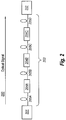
- Figure 2 illustrates an optical system 200 that mav operate in a repeatered or unrepeatered optical link, and that may operate in a terrestrial and/or submarine optical link.
- the optical system 200 includes an optical transmission node 201 at one end of the optical fiber link 203, and an optical reception node 202 at the other end of the optical fiber link 203.
- the transmission node 201 of Figure 2 may be, may include, or may be included within terminal 101 of Figure 1 and the reception node 202 of Figure 2 may be, may include, or may be included within the terminal 102 of Figure 1 .
- the transmission node 201 of Figure 2 may be, may include, or may be included within the terminal 101 of Figure 1 , or an optical add-drop multiplexer between terminals 101 and 102.
- the reception node 202 of Figure 2 may be, may include, or may be included within the terminal 102 of Figure 1 or an optical add-drop multiplexer between terminals 101 and 102.
- the optical link 203 includes a series of distributed dispersion compensating mechanisms 204, each separate in the optical path by one or more optically dispersive line fiber segments 205.
- distributed dispersion compensation mechanisms 204A, 204B and 204C referred to collectively as "dispersion compensation mechanisms 204".
- the dispersion compensating mechanisms 204 might be dispersion compensating modules, as might be common in a terrestrial long-haul optical link.
- Submarine long-haul optical links on the other hand, often only consist of line fiber segments between repeaters/terminals.
- the dispersion compensating mechanisms 204 may each simply be dispersion compensative fiber segments that compensate for the dispersive fiber segments 205.
- optical fiber segment 205 there is but one optical fiber segment between each dispersion compensation mechanism.
- the four optical fiber segments 205A, 205B, 205C and 205D may be referred to hereinafter as "fiber segments 205".
- dispersion compensating modules DCMs
- dispersion compensating fiber may be placed into the optical link.
- DCMs dispersion compensating modules
- a "dispersion map" is a plot of accumulated dispersion versus distance in an optical link from the transmission node to the receiver node including dispersion at the transmission node and receiver node.
- a few examples of dispersion maps are illustrated with respect to Figures 4A and 4B , and Figures 5A and 5B , and will be described further below.
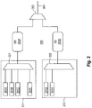
- Figure 3 illustrates an example of an optical transmission node 300 which represents one example of the optical transmission node 201 of Figure 2 .
- the optical transmission node 300 may also be referred to herein as an optical introduction node as it introduces or merges non-coherent optical wavelength channels and coherent optical wavelength channels to be transmitted down optical link 203 as will be described further herein.
- the optical transmission node 300 has access to a non-coherent source 311 that provides one or more non-coherent optical wavelength channels.
- Non-coherent optical wavelength channels are the optical wavelength channels that will be directly (or non-coherently) detected without measuring the phase and amplitude of electric field of the optical signal.
- the non-coherent source 311 provides a set of six non-coherent optical wavelength channels 301A through 301F.
- An optical multiplexer 321 combines all of the non-coherent optical wavelength channels.
- the optical transmission node 300 also has access to a coherent source 312 that provides one or more coherent optical wavelength channels.
- Coherent optical wavelength channels are the optical wavelength channels that will be coherently detected.
- the coherent source 312 provides a set of two coherent optical wavelength channels 301G and 301H.
- An optical multiplexer 322 combines all of the coherent optical wavelength channels.
- the optical wavelength channels 301A through 301H may be in, for example, the C-band and/or L-band, and may be Wavelength Division Multiplexed (WDM) signals or Dense WDM (DWDM) optical channels.
- WDM Wavelength Division Multiplexed
- DWDM Dense WDM
- the non-coherent optical wavelength channels are to have one dispersion map (called hereinafter a "non-coherent dispersion map”), and the coherent optical wavelength channels are to have another significantly different dispersion map (called hereinafter a “coherent dispersion map”).
- Coherent and non-coherent detection mechanisms are very different in their sensitivity to dispersion maps.
- non-coherent detection also called “direct detection”
- direct detection may also rely on a final dispersion compensation that reduces the total accumulated optical dispersion to low levels.
- dispersion maps may be formulated for optical wavelength channels that are to be subjected to coherent detection as opposed to direct detection.
- the six non-coherent optical wavelength channels 301A through 301F are illustrated as being introduced into multiplexer 321 which combines the channels into one fiber and further passes the channels through optional dispersive element (DE) 302A at the transmission node 300.
- the six optical wavelength channels 301A through 301F are illustrated as being introduced to the DE 302A as a single signal, that is not required.
- the two coherent optical wavelength channels 301G and 301H are illustrated as being introduced into multiplexer 322 which combines the channels into one fiber and further passes the channels through DE 302B at the transmission node 300.
- the two optical wavelength channels 301G and 301H are illustrated as being introduced to the DE 302B as a single signal, that is not required.
- the set of non-coherent optical wavelength channels 301A through 301F (hereinafter also referred to as the "non-coherent channel set” or “non-coherent optical wavelength channel set”) and the set of coherent optical wavelength channels 301G and 301H (hereinafter also referred to as the “coherent channel set” or “coherent optical wavelength channel set”) are subjected to different applied dispersion at the transmission node 300.
- the DE 302A is optional because, depending on the implementation, a DE 302A might not be needed for the non-coherent channel set in order to achieve the desired separation in the non-coherent and coherent dispersion maps.
- the DE 302B is optional because, depending on the implementation, a DE 302B might not be needed for the coherent channel set in order to achieve the desired separation in the non-coherent and coherent dispersion maps.
- the DE 302A and the DE 302B may be any dispersion mechanism, even unconventional dispersion mechanisms. For instance, a chirped modulator may be used to introduce a certain amount of dispersion into a signal.
- the DEs 302A and 302B may be considered in their aggregate to be a dispersion element that introduces different dispersion levels into either or both of the coherent optical wavelength channels and the non-coherent optical wavelength channels such that the one or more coherent optical wavelength channels have a shifted dispersion map as compared to the one or more non-coherent optical wavelength channels.
- the optical wavelength channels that represent the main flow of optical channels may already be in combined form, thereby obviating the need for a multiplexer.
- the non-coherent optical wavelength channels 301A through 301F may already be combined, thereby negating the need for a multiplexer 321.
- the transmission node 300 is not the point of generation of the optical wavelength channels 301G and 301H, then the coherent optical wavelength channels 301G and 301H might also be already combined thereby negating the need for multiplexer 322.
- source 312 represents a set of coherent optical wavelength channels that is either generated locally or generated remotely and transported to the add/drop multiplexer to be added to the set of non-coherent optical wavelength channels 311.
- the optical wavelength channels 301A though 301H may each be generated using distinct transmitters, and thus in that case, the multiplexers 321 and 322 may be used.
- An optical multiplexer 303 combines each of the coherent channel set and the non-coherent channel set into a single mixed signal 304 for transmission onto the optical link.
- the non-coherent channel set is dispatched onto the optical link with a different accumulated dispersion as compared to the coherent channel set.
- the accumulated dispersion of the first channel set would remain offset from the accumulated dispersion of the second channel set.
- the dispersive element within the transmission node 300 causes the coherent dispersion map to be shifted by at least 1000 ps/nm from the zero dispersion point.
- the coherent dispersion map may also be shifted by 2000 ps/nm from the zero dispersion point. However, since coherent dispersion maps may be shifted up to 50,000 ps/nm, even more dispersion shifting may be performed.
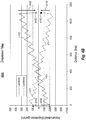
- FIGS. 4A and 4B illustrate dispersion maps possible using conventional systems.
- a dispersion map is referred to herein as "positive” if the total accumulated dispersion excluding the dispersion in the transmission and receiver node is greater than zero (which is to say that the dispersion map just prior to the receiver node has greater accumulated dispersion than the dispersion map just after the transmission node).
- a dispersion map is referred to herein as "negative” if the total accumulated dispersion excluding the dispersion in the transmission and receiver node is less than zero (which is to say that the dispersion map just prior to the receiver node has less accumulated dispersion than the dispersion map just after the transmission node).
- Figure 4A is a typical positive dispersion map 400A of an optical link with DCMs in every span.
- a dispersion map 401 shown for a first wavelength (lambda 1 - represented by the solid line), and a dispersion map 402 shown for a second wavelength (lambda2 - represented by the dashed line).
- the dispersion maps are positive.
- the arrows 401A and 401B at the transmit (Tx) and receive (Rx) side, respectively, show DCM-applied dispersion compensation that are applied at the Tx and Rx terminals, often referred to as pre-compensation and post-compensation, respectively.
- the square 401C show the total accumulated dispersion of lambda1 which is close to zero.
- the square 402C show the total accumulated dispersion of lambda2 which is also close to zero.
- the pre-compensation is the same DCM for all channels, which is relatively common in conventional optical links.
- dispersion map 410 for one optical wavelength channel (lambda1 - represented by the solid line), and another dispersion map 411 for another optical wavelength channel (lambda2 - represented by the dashed line). Since the dispersion map is a function of the optical wavelength, it may be possible that the dispersion map is positive at some wavelengths and negative at other wavelengths.
- Figure 4B shows a condition in which the dispersion map 410 for the lambda1 wavelength is positive, whereas the dispersion map 411 for the lambda2 wavelength is negative.
- FIG 4B there is a different pre-compensation 410A and 411A performed on each optical wavelength channel for each dispersion map 410 and 411, respectively, and a different post-compensation 410B and 411B performed for each dispersion map 410 and 411, respectively.
- squares 410C and 411C show the final accumulated dispersion after post-compensation.
- the pre-compensation is different for different non-coherent channels. This is done in order to keep the dispersion map average value closer to zero when there is a large variation of dispersion with wavelength. There are some nonlinear penalties that occur for direct-detected channels when the dispersion map is too regular around zero dispersion, so it is common to apply pre-compensation in these cases.
- Figure 5A is similar to Figure 4A , except that now a shifted dispersion map 501 is generated by applying a dispersion 501A at the transmission node.
- the dispersion map avoids crossing zero dispersion (or getting too close to zero) in the link between terminals.
- the dispersion map remains such that, at any given point, the accumulated dispersion remains positive, and in fact, is above 500 ps/nm. If the optical wavelength channel were a coherent channel, then no post-compensation is needed since Figure 5A clearly shows the final accumulated dispersion 501C to be well within the 50,000 ps/nm tolerance. However, if this tolerance level were approached or exceeded, post-compensation could be employed to get within the tolerance range.
- the dispersion 501A introduced at the transmission node is positive even though the trend of the dispersion map is positively sloped. This is counterintuitive in conventional systems as negative dispersion would typically be introduced at the transmission terminal to compensate for an expected positive slope in the trend of the dispersion accumulation. For instance, in Figure 4A , a negative dispersion 401A is added in order to account for an expected positive trend line in the dispersion accumulation.
- a negative dispersion may be introduced to coherent channels that are to be introduced with non-coherent channels, even though the trend line of the dispersion accumulation is also negative.
- a negative dispersion might be introduced by the transmission node to the coherent optical wavelength channels, resulting in the dispersion map having (at any given point) a negative accumulated dispersion (and perhaps even an accumulated dispersion less than minus 500 ps/nm) after the transmission node.
- Figure 5B is similar to Figure 4B , except that now a shifted dispersion map 510 is generated by applying dispersion 510A at the transmission node, resulting in a final accumulated dispersion 510C at the reception node.
- the shifted dispersion map 510 is represented corresponding to a wavelength near lamda1.
- the shifted dispersion map for wavelengths near lambda2 is not illustrated in Figure 2 , but would result in a dispersion map that trended even more negative.
- the dispersion map 510 avoids crossing zero dispersion (or getting too close to zero) in the link between terminals. If the optical wavelength channel were a coherent channel, then no post-compensation is needed unless the 50,000 ps/nm tolerance is approached or exceeded. Note that the different methodology between dispersion map 510 of Figure 5B and the dispersion map 410 of Figure 4B .
- the dispersion introduced to the coherent channels resulting in dispersion map 510 is sufficient such that the coherent dispersion map 510 does not intersect with any of the dispersion maps of the non-coherent channels while dispersion map 410 normally intersects with the other dispersion maps of other non-coherent channels in the signal band.
- either the minimum of the dispersion map of any coherent optical wavelength channel of the coherent optical wavelength channel set is greater than the maximum of the dispersion map of any of the non-coherent optical wavelength channels of the non-coherent optical wavelength channel set at any point within the entire optical fiber link after the introduction node, or the maximum of the dispersion map of any coherent optical wavelength channel of the coherent optical wavelength channel set is less than the minimum of the dispersion map of any of the non-coherent optical wavelength channels of the non-coherent optical wavelength channel set at any point within the entire optical fiber link after the introduction node.
- the dispersion introduced could be sufficient to shift the dispersion map 510 to be no closer than 500 picoseconds per nanometer from the dispersion map of any non-coherent optical wavelength channels at any given point in the optical fiber link after the transmission node. In another embodiment, the dispersion introduced could have sufficient to shift the dispersion map 510 to be less than -500 picoseconds per nanometer at any given point in the optical fiber link after the transmission node.
- a mechanism for mixing dispersion maps for mixed coherent and non-coherent optical channels in a single optical link is described. This may be accomplished even without changing the optical link itself. In situations in which the optical link is lengthy (e.g., hundreds or thousands of kilometers), or positioned in difficult locations (e.g., at the bottom of the ocean), the ability to apply two significantly distinct dispersion maps to different sets of optical wavelength channels is helpful.
- the bit rate of the optical channels to be subjected to the second dispersion map may be different than the bit rate of the optical wavelength channels to be subjected to the first dispersion map.
- the principles described herein may allow for some upgrading of an existing optical link without modifying the optical link and inline dispersion compensation.
- the configuration of the existing (for example, non-coherent channels) are not allowed to be changed at all.
- the principles described herein may allow for the addition of upgrade channels (for example, coherent channels) to an existing optical link that was designed to be optimized for non-coherent channels.
Landscapes
- Physics & Mathematics (AREA)
- Electromagnetism (AREA)
- Engineering & Computer Science (AREA)
- Computer Networks & Wireless Communication (AREA)
- Signal Processing (AREA)
- Optical Communication System (AREA)
Applications Claiming Priority (4)
| Application Number | Priority Date | Filing Date | Title |
|---|---|---|---|
| US25544809P | 2009-10-27 | 2009-10-27 | |
| US12/909,721 US8380069B2 (en) | 2009-10-27 | 2010-10-21 | Introduction-side dispersion shifting of channels |
| PCT/US2010/054107 WO2011056579A1 (fr) | 2009-10-27 | 2010-10-26 | Décalage de canaux à dispersion de côté d'introduction |
| EP10776870.7A EP2494717B1 (fr) | 2009-10-27 | 2010-10-26 | Décalage de canaux à dispersion de côté d'introduction |
Related Parent Applications (1)
| Application Number | Title | Priority Date | Filing Date |
|---|---|---|---|
| EP10776870.7A Division EP2494717B1 (fr) | 2009-10-27 | 2010-10-26 | Décalage de canaux à dispersion de côté d'introduction |
Publications (2)
| Publication Number | Publication Date |
|---|---|
| EP3324558A1 true EP3324558A1 (fr) | 2018-05-23 |
| EP3324558B1 EP3324558B1 (fr) | 2019-03-13 |
Family
ID=43898536
Family Applications (3)
| Application Number | Title | Priority Date | Filing Date |
|---|---|---|---|
| EP10776870.7A Active EP2494717B1 (fr) | 2009-10-27 | 2010-10-26 | Décalage de canaux à dispersion de côté d'introduction |
| EP17186286.5A Active EP3324558B1 (fr) | 2009-10-27 | 2010-10-26 | Décalage de dispersion de canaux sur côté d'introduction |
| EP10776470.6A Not-in-force EP2494716B1 (fr) | 2009-10-27 | 2010-10-26 | Compensation de dispersion distincte pour canaux cohérents et canaux non cohérents |
Family Applications Before (1)
| Application Number | Title | Priority Date | Filing Date |
|---|---|---|---|
| EP10776870.7A Active EP2494717B1 (fr) | 2009-10-27 | 2010-10-26 | Décalage de canaux à dispersion de côté d'introduction |
Family Applications After (1)
| Application Number | Title | Priority Date | Filing Date |
|---|---|---|---|
| EP10776470.6A Not-in-force EP2494716B1 (fr) | 2009-10-27 | 2010-10-26 | Compensation de dispersion distincte pour canaux cohérents et canaux non cohérents |
Country Status (4)
| Country | Link |
|---|---|
| US (2) | US8380068B2 (fr) |
| EP (3) | EP2494717B1 (fr) |
| JP (2) | JP2013509136A (fr) |
| WO (2) | WO2011056579A1 (fr) |
Families Citing this family (6)
| Publication number | Priority date | Publication date | Assignee | Title |
|---|---|---|---|---|
| JP5636712B2 (ja) * | 2010-03-23 | 2014-12-10 | 富士通株式会社 | 信号光処理装置、光伝送装置及び信号光処理方法 |
| US20110318019A1 (en) * | 2010-06-29 | 2011-12-29 | Tyco Electronics Subsea Communication LLC | Communication transmission system with optically aided digital signal processing dispersion compensation |
| US9300402B2 (en) * | 2010-12-14 | 2016-03-29 | Tyco Electronics Subsea Communications Llc | Dispersion management in optical networks including both coherent and direct detection receivers |
| US20150110143A1 (en) * | 2013-03-13 | 2015-04-23 | Xtera Communications, Inc. | Adjustable impedance laser driver |
| GB2514134B (en) * | 2013-05-14 | 2016-05-25 | Toshiba Res Europe Ltd | A signal manipulator for a quantum communication system |
| US20170170910A1 (en) | 2015-12-14 | 2017-06-15 | Nikola Alic | Increase in reach of unrepeatered fiber transmission |
Citations (6)
| Publication number | Priority date | Publication date | Assignee | Title |
|---|---|---|---|---|
| EP1241810A2 (fr) * | 2001-03-15 | 2002-09-18 | Fujikura Ltd. | Voie de transmission à multiplexage en longueurs d'ondes et fibre pour la compensation de la dispersion utilisée à cet effet |
| US20020159136A1 (en) * | 2000-12-13 | 2002-10-31 | Zhenguo Lu | Very low noise figure optical amplifier devices |
| EP1261153A1 (fr) * | 2001-05-14 | 2002-11-27 | Alcatel | Module optique pour gestion de dispersion en parallèle |
| WO2004114530A2 (fr) * | 2003-06-20 | 2004-12-29 | Corvis Corporation | Systemes, dispositifs et procedes de commande d'interactions optiques non lineaires |
| US20080084605A1 (en) * | 2006-10-05 | 2008-04-10 | Rothenberg Joshua E | Method and system for hybrid coherent and incoherent diffractive beam combining |
| US7499173B1 (en) * | 2005-11-28 | 2009-03-03 | At&T Corp. | Interferometric method and apparatus for measuring optical signal quality in optical communications system |
Family Cites Families (13)
| Publication number | Priority date | Publication date | Assignee | Title |
|---|---|---|---|---|
| JP3396270B2 (ja) * | 1993-08-10 | 2003-04-14 | 富士通株式会社 | 光分散補償方式 |
| US6587261B1 (en) * | 1999-05-24 | 2003-07-01 | Corvis Corporation | Optical transmission systems including optical amplifiers and methods of use therein |
| HK1047199A1 (zh) * | 1999-07-19 | 2003-02-07 | 住友电气工业株式会社 | 以散补偿系统 |
| JP4491268B2 (ja) * | 2004-04-21 | 2010-06-30 | 富士通株式会社 | 分散補償量設定方法,受信端局および波長多重光伝送システム |
| JP2005341392A (ja) * | 2004-05-28 | 2005-12-08 | Fujitsu Ltd | 光伝送装置、光伝送システムおよび分散補償方法 |
| US20060029398A1 (en) * | 2004-08-06 | 2006-02-09 | Li Liu | Transmission of optical signals of different modulation formats in discrete bands |
| US7609969B2 (en) * | 2005-12-19 | 2009-10-27 | Fujitsu Limited | Method and system for compensating for optical dispersion in an optical signal |
| JP4571933B2 (ja) * | 2006-12-28 | 2010-10-27 | 富士通株式会社 | 光伝送装置および光伝送方法 |
| JP4701192B2 (ja) * | 2007-02-01 | 2011-06-15 | 富士通株式会社 | 伝送システムおよび伝送方法 |
| JP5088191B2 (ja) * | 2008-03-21 | 2012-12-05 | 富士通株式会社 | 光伝送システム及びその分散補償方法 |
| JP2009213160A (ja) * | 2009-06-15 | 2009-09-17 | Fujitsu Ltd | 光伝送装置 |
| JP2011035735A (ja) * | 2009-08-03 | 2011-02-17 | Fujitsu Ltd | 伝送装置,伝送システムおよび通信方法 |
| CN102484532B (zh) * | 2009-09-02 | 2015-08-12 | 富士通株式会社 | 通信系统、色散斜率赋予器以及通信方法 |
-
2010
- 2010-09-30 US US12/895,585 patent/US8380068B2/en active Active
- 2010-10-21 US US12/909,721 patent/US8380069B2/en active Active
- 2010-10-26 EP EP10776870.7A patent/EP2494717B1/fr active Active
- 2010-10-26 WO PCT/US2010/054107 patent/WO2011056579A1/fr not_active Ceased
- 2010-10-26 WO PCT/US2010/054113 patent/WO2011056583A1/fr not_active Ceased
- 2010-10-26 JP JP2012536956A patent/JP2013509136A/ja active Pending
- 2010-10-26 JP JP2012536953A patent/JP5438838B2/ja active Active
- 2010-10-26 EP EP17186286.5A patent/EP3324558B1/fr active Active
- 2010-10-26 EP EP10776470.6A patent/EP2494716B1/fr not_active Not-in-force
Patent Citations (6)
| Publication number | Priority date | Publication date | Assignee | Title |
|---|---|---|---|---|
| US20020159136A1 (en) * | 2000-12-13 | 2002-10-31 | Zhenguo Lu | Very low noise figure optical amplifier devices |
| EP1241810A2 (fr) * | 2001-03-15 | 2002-09-18 | Fujikura Ltd. | Voie de transmission à multiplexage en longueurs d'ondes et fibre pour la compensation de la dispersion utilisée à cet effet |
| EP1261153A1 (fr) * | 2001-05-14 | 2002-11-27 | Alcatel | Module optique pour gestion de dispersion en parallèle |
| WO2004114530A2 (fr) * | 2003-06-20 | 2004-12-29 | Corvis Corporation | Systemes, dispositifs et procedes de commande d'interactions optiques non lineaires |
| US7499173B1 (en) * | 2005-11-28 | 2009-03-03 | At&T Corp. | Interferometric method and apparatus for measuring optical signal quality in optical communications system |
| US20080084605A1 (en) * | 2006-10-05 | 2008-04-10 | Rothenberg Joshua E | Method and system for hybrid coherent and incoherent diffractive beam combining |
Also Published As
| Publication number | Publication date |
|---|---|
| US8380068B2 (en) | 2013-02-19 |
| US8380069B2 (en) | 2013-02-19 |
| JP5438838B2 (ja) | 2014-03-12 |
| EP2494716B1 (fr) | 2017-10-11 |
| EP3324558B1 (fr) | 2019-03-13 |
| EP2494717A1 (fr) | 2012-09-05 |
| JP2013509136A (ja) | 2013-03-07 |
| WO2011056583A1 (fr) | 2011-05-12 |
| US20110097087A1 (en) | 2011-04-28 |
| EP2494717B1 (fr) | 2017-08-16 |
| JP2013509135A (ja) | 2013-03-07 |
| US20110097088A1 (en) | 2011-04-28 |
| WO2011056579A1 (fr) | 2011-05-12 |
| EP2494716A1 (fr) | 2012-09-05 |
Similar Documents
| Publication | Publication Date | Title |
|---|---|---|
| US8320772B2 (en) | Optical transmission apparatus | |
| US8351798B2 (en) | Phase shift keyed high speed signaling | |
| US8331786B2 (en) | Transmission method of WDM light and WDM optical transmission system | |
| JP4701192B2 (ja) | 伝送システムおよび伝送方法 | |
| EP3324558B1 (fr) | Décalage de dispersion de canaux sur côté d'introduction | |
| US8401389B2 (en) | Method and system for compensating for optical dispersion in an optical signal | |
| US7693425B2 (en) | Method and system for compensating for optical dispersion in an optical signal in a hybrid optical network | |
| CN100578973C (zh) | 波分复用光传输系统以及波分复用光传输方法 | |
| US10069589B2 (en) | Method and apparatus for increasing a transmission performance of a hybrid wavelength division multiplexing system | |
| JP2018128673A (ja) | ファイバー・ブラッグ格子移相器を用いた光位相感応増幅器 | |
| JP2008532435A (ja) | 分散勾配補償を有する光伝送システム | |
| JP4827672B2 (ja) | Wdm光伝送システムおよびwdm光伝送方法 | |
| EP3120471A1 (fr) | Liaison de communication optique multi-portée avec amplificateur à pompage optique distant | |
| Birk et al. | Field trial of end-to-end OC-768 transmission using 9 WDM channels over 1000km of installed fiber | |
| Kiaee et al. | Design of a 32× 5 Gb/s DWDM Optical Network over a Distance of 1000 km | |
| US7734187B2 (en) | Dispersion management in optical networks using a differential phase shift keying modulation format | |
| Salsi | Ultra-long-haul coherent transmission for submarine applications | |
| Bobrovs et al. | Realization of Mixed WDM Transmission System |
Legal Events
| Date | Code | Title | Description |
|---|---|---|---|
| PUAI | Public reference made under article 153(3) epc to a published international application that has entered the european phase |
Free format text: ORIGINAL CODE: 0009012 |
|
| STAA | Information on the status of an ep patent application or granted ep patent |
Free format text: STATUS: THE APPLICATION HAS BEEN PUBLISHED |
|
| AC | Divisional application: reference to earlier application |
Ref document number: 2494717 Country of ref document: EP Kind code of ref document: P |
|
| AK | Designated contracting states |
Kind code of ref document: A1 Designated state(s): AL AT BE BG CH CY CZ DE DK EE ES FI FR GB GR HR HU IE IS IT LI LT LU LV MC MK MT NL NO PL PT RO RS SE SI SK SM TR |
|
| STAA | Information on the status of an ep patent application or granted ep patent |
Free format text: STATUS: REQUEST FOR EXAMINATION WAS MADE |
|
| 17P | Request for examination filed |
Effective date: 20180518 |
|
| GRAP | Despatch of communication of intention to grant a patent |
Free format text: ORIGINAL CODE: EPIDOSNIGR1 |
|
| STAA | Information on the status of an ep patent application or granted ep patent |
Free format text: STATUS: GRANT OF PATENT IS INTENDED |
|
| INTG | Intention to grant announced |
Effective date: 20180718 |
|
| GRAS | Grant fee paid |
Free format text: ORIGINAL CODE: EPIDOSNIGR3 |
|
| RBV | Designated contracting states (corrected) |
Designated state(s): AL AT BE BG CH CY CZ DE DK EE ES FI FR GB GR HR HU IE IS IT LI LT LU LV MC MK MT NL NO PL PT RO RS SE SI SK SM TR |
|
| GRAA | (expected) grant |
Free format text: ORIGINAL CODE: 0009210 |
|
| STAA | Information on the status of an ep patent application or granted ep patent |
Free format text: STATUS: THE PATENT HAS BEEN GRANTED |
|
| AC | Divisional application: reference to earlier application |
Ref document number: 2494717 Country of ref document: EP Kind code of ref document: P |
|
| AK | Designated contracting states |
Kind code of ref document: B1 Designated state(s): AL AT BE BG CH CY CZ DE DK EE ES FI FR GB GR HR HU IE IS IT LI LT LU LV MC MK MT NL NO PL PT RO RS SE SI SK SM TR |
|
| REG | Reference to a national code |
Ref country code: GB Ref legal event code: FG4D |
|
| REG | Reference to a national code |
Ref country code: CH Ref legal event code: EP Ref country code: AT Ref legal event code: REF Ref document number: 1109115 Country of ref document: AT Kind code of ref document: T Effective date: 20190315 |
|
| REG | Reference to a national code |
Ref country code: IE Ref legal event code: FG4D |
|
| REG | Reference to a national code |
Ref country code: DE Ref legal event code: R096 Ref document number: 602010057644 Country of ref document: DE |
|
| REG | Reference to a national code |
Ref country code: NL Ref legal event code: MP Effective date: 20190313 |
|
| REG | Reference to a national code |
Ref country code: LT Ref legal event code: MG4D |
|
| PG25 | Lapsed in a contracting state [announced via postgrant information from national office to epo] |
Ref country code: FI Free format text: LAPSE BECAUSE OF FAILURE TO SUBMIT A TRANSLATION OF THE DESCRIPTION OR TO PAY THE FEE WITHIN THE PRESCRIBED TIME-LIMIT Effective date: 20190313 Ref country code: NO Free format text: LAPSE BECAUSE OF FAILURE TO SUBMIT A TRANSLATION OF THE DESCRIPTION OR TO PAY THE FEE WITHIN THE PRESCRIBED TIME-LIMIT Effective date: 20190613 Ref country code: SE Free format text: LAPSE BECAUSE OF FAILURE TO SUBMIT A TRANSLATION OF THE DESCRIPTION OR TO PAY THE FEE WITHIN THE PRESCRIBED TIME-LIMIT Effective date: 20190313 Ref country code: LT Free format text: LAPSE BECAUSE OF FAILURE TO SUBMIT A TRANSLATION OF THE DESCRIPTION OR TO PAY THE FEE WITHIN THE PRESCRIBED TIME-LIMIT Effective date: 20190313 |
|
| PG25 | Lapsed in a contracting state [announced via postgrant information from national office to epo] |
Ref country code: BG Free format text: LAPSE BECAUSE OF FAILURE TO SUBMIT A TRANSLATION OF THE DESCRIPTION OR TO PAY THE FEE WITHIN THE PRESCRIBED TIME-LIMIT Effective date: 20190613 Ref country code: LV Free format text: LAPSE BECAUSE OF FAILURE TO SUBMIT A TRANSLATION OF THE DESCRIPTION OR TO PAY THE FEE WITHIN THE PRESCRIBED TIME-LIMIT Effective date: 20190313 Ref country code: NL Free format text: LAPSE BECAUSE OF FAILURE TO SUBMIT A TRANSLATION OF THE DESCRIPTION OR TO PAY THE FEE WITHIN THE PRESCRIBED TIME-LIMIT Effective date: 20190313 Ref country code: RS Free format text: LAPSE BECAUSE OF FAILURE TO SUBMIT A TRANSLATION OF THE DESCRIPTION OR TO PAY THE FEE WITHIN THE PRESCRIBED TIME-LIMIT Effective date: 20190313 Ref country code: HR Free format text: LAPSE BECAUSE OF FAILURE TO SUBMIT A TRANSLATION OF THE DESCRIPTION OR TO PAY THE FEE WITHIN THE PRESCRIBED TIME-LIMIT Effective date: 20190313 Ref country code: GR Free format text: LAPSE BECAUSE OF FAILURE TO SUBMIT A TRANSLATION OF THE DESCRIPTION OR TO PAY THE FEE WITHIN THE PRESCRIBED TIME-LIMIT Effective date: 20190614 |
|
| REG | Reference to a national code |
Ref country code: AT Ref legal event code: MK05 Ref document number: 1109115 Country of ref document: AT Kind code of ref document: T Effective date: 20190313 |
|
| PG25 | Lapsed in a contracting state [announced via postgrant information from national office to epo] |
Ref country code: IT Free format text: LAPSE BECAUSE OF FAILURE TO SUBMIT A TRANSLATION OF THE DESCRIPTION OR TO PAY THE FEE WITHIN THE PRESCRIBED TIME-LIMIT Effective date: 20190313 Ref country code: RO Free format text: LAPSE BECAUSE OF FAILURE TO SUBMIT A TRANSLATION OF THE DESCRIPTION OR TO PAY THE FEE WITHIN THE PRESCRIBED TIME-LIMIT Effective date: 20190313 Ref country code: SK Free format text: LAPSE BECAUSE OF FAILURE TO SUBMIT A TRANSLATION OF THE DESCRIPTION OR TO PAY THE FEE WITHIN THE PRESCRIBED TIME-LIMIT Effective date: 20190313 Ref country code: AL Free format text: LAPSE BECAUSE OF FAILURE TO SUBMIT A TRANSLATION OF THE DESCRIPTION OR TO PAY THE FEE WITHIN THE PRESCRIBED TIME-LIMIT Effective date: 20190313 Ref country code: PT Free format text: LAPSE BECAUSE OF FAILURE TO SUBMIT A TRANSLATION OF THE DESCRIPTION OR TO PAY THE FEE WITHIN THE PRESCRIBED TIME-LIMIT Effective date: 20190713 Ref country code: EE Free format text: LAPSE BECAUSE OF FAILURE TO SUBMIT A TRANSLATION OF THE DESCRIPTION OR TO PAY THE FEE WITHIN THE PRESCRIBED TIME-LIMIT Effective date: 20190313 Ref country code: ES Free format text: LAPSE BECAUSE OF FAILURE TO SUBMIT A TRANSLATION OF THE DESCRIPTION OR TO PAY THE FEE WITHIN THE PRESCRIBED TIME-LIMIT Effective date: 20190313 Ref country code: CZ Free format text: LAPSE BECAUSE OF FAILURE TO SUBMIT A TRANSLATION OF THE DESCRIPTION OR TO PAY THE FEE WITHIN THE PRESCRIBED TIME-LIMIT Effective date: 20190313 |
|
| PG25 | Lapsed in a contracting state [announced via postgrant information from national office to epo] |
Ref country code: SM Free format text: LAPSE BECAUSE OF FAILURE TO SUBMIT A TRANSLATION OF THE DESCRIPTION OR TO PAY THE FEE WITHIN THE PRESCRIBED TIME-LIMIT Effective date: 20190313 Ref country code: PL Free format text: LAPSE BECAUSE OF FAILURE TO SUBMIT A TRANSLATION OF THE DESCRIPTION OR TO PAY THE FEE WITHIN THE PRESCRIBED TIME-LIMIT Effective date: 20190313 |
|
| REG | Reference to a national code |
Ref country code: DE Ref legal event code: R097 Ref document number: 602010057644 Country of ref document: DE |
|
| PG25 | Lapsed in a contracting state [announced via postgrant information from national office to epo] |
Ref country code: IS Free format text: LAPSE BECAUSE OF FAILURE TO SUBMIT A TRANSLATION OF THE DESCRIPTION OR TO PAY THE FEE WITHIN THE PRESCRIBED TIME-LIMIT Effective date: 20190713 Ref country code: AT Free format text: LAPSE BECAUSE OF FAILURE TO SUBMIT A TRANSLATION OF THE DESCRIPTION OR TO PAY THE FEE WITHIN THE PRESCRIBED TIME-LIMIT Effective date: 20190313 |
|
| PLBE | No opposition filed within time limit |
Free format text: ORIGINAL CODE: 0009261 |
|
| STAA | Information on the status of an ep patent application or granted ep patent |
Free format text: STATUS: NO OPPOSITION FILED WITHIN TIME LIMIT |
|
| PG25 | Lapsed in a contracting state [announced via postgrant information from national office to epo] |
Ref country code: DK Free format text: LAPSE BECAUSE OF FAILURE TO SUBMIT A TRANSLATION OF THE DESCRIPTION OR TO PAY THE FEE WITHIN THE PRESCRIBED TIME-LIMIT Effective date: 20190313 |
|
| 26N | No opposition filed |
Effective date: 20191216 |
|
| PG25 | Lapsed in a contracting state [announced via postgrant information from national office to epo] |
Ref country code: TR Free format text: LAPSE BECAUSE OF FAILURE TO SUBMIT A TRANSLATION OF THE DESCRIPTION OR TO PAY THE FEE WITHIN THE PRESCRIBED TIME-LIMIT Effective date: 20190313 |
|
| PG25 | Lapsed in a contracting state [announced via postgrant information from national office to epo] |
Ref country code: MC Free format text: LAPSE BECAUSE OF FAILURE TO SUBMIT A TRANSLATION OF THE DESCRIPTION OR TO PAY THE FEE WITHIN THE PRESCRIBED TIME-LIMIT Effective date: 20190313 |
|
| REG | Reference to a national code |
Ref country code: CH Ref legal event code: PL |
|
| PG25 | Lapsed in a contracting state [announced via postgrant information from national office to epo] |
Ref country code: CH Free format text: LAPSE BECAUSE OF NON-PAYMENT OF DUE FEES Effective date: 20191031 Ref country code: LU Free format text: LAPSE BECAUSE OF NON-PAYMENT OF DUE FEES Effective date: 20191026 Ref country code: LI Free format text: LAPSE BECAUSE OF NON-PAYMENT OF DUE FEES Effective date: 20191031 |
|
| REG | Reference to a national code |
Ref country code: BE Ref legal event code: MM Effective date: 20191031 |
|
| PG25 | Lapsed in a contracting state [announced via postgrant information from national office to epo] |
Ref country code: BE Free format text: LAPSE BECAUSE OF NON-PAYMENT OF DUE FEES Effective date: 20191031 |
|
| PG25 | Lapsed in a contracting state [announced via postgrant information from national office to epo] |
Ref country code: IE Free format text: LAPSE BECAUSE OF NON-PAYMENT OF DUE FEES Effective date: 20191026 |
|
| PG25 | Lapsed in a contracting state [announced via postgrant information from national office to epo] |
Ref country code: CY Free format text: LAPSE BECAUSE OF FAILURE TO SUBMIT A TRANSLATION OF THE DESCRIPTION OR TO PAY THE FEE WITHIN THE PRESCRIBED TIME-LIMIT Effective date: 20190313 |
|
| PG25 | Lapsed in a contracting state [announced via postgrant information from national office to epo] |
Ref country code: HU Free format text: LAPSE BECAUSE OF FAILURE TO SUBMIT A TRANSLATION OF THE DESCRIPTION OR TO PAY THE FEE WITHIN THE PRESCRIBED TIME-LIMIT; INVALID AB INITIO Effective date: 20101026 Ref country code: MT Free format text: LAPSE BECAUSE OF FAILURE TO SUBMIT A TRANSLATION OF THE DESCRIPTION OR TO PAY THE FEE WITHIN THE PRESCRIBED TIME-LIMIT Effective date: 20190313 |
|
| PG25 | Lapsed in a contracting state [announced via postgrant information from national office to epo] |
Ref country code: SI Free format text: LAPSE BECAUSE OF FAILURE TO SUBMIT A TRANSLATION OF THE DESCRIPTION OR TO PAY THE FEE WITHIN THE PRESCRIBED TIME-LIMIT Effective date: 20190313 |
|
| PG25 | Lapsed in a contracting state [announced via postgrant information from national office to epo] |
Ref country code: MK Free format text: LAPSE BECAUSE OF FAILURE TO SUBMIT A TRANSLATION OF THE DESCRIPTION OR TO PAY THE FEE WITHIN THE PRESCRIBED TIME-LIMIT Effective date: 20190313 |
|
| P01 | Opt-out of the competence of the unified patent court (upc) registered |
Effective date: 20230518 |
|
| PGFP | Annual fee paid to national office [announced via postgrant information from national office to epo] |
Ref country code: GB Payment date: 20250923 Year of fee payment: 16 |
|
| PGFP | Annual fee paid to national office [announced via postgrant information from national office to epo] |
Ref country code: FR Payment date: 20250924 Year of fee payment: 16 |
|
| PGFP | Annual fee paid to national office [announced via postgrant information from national office to epo] |
Ref country code: DE Payment date: 20250923 Year of fee payment: 16 |