EP3324701B1 - Unité radio à distance, récepteur et station de base - Google Patents
Unité radio à distance, récepteur et station de base Download PDFInfo
- Publication number
- EP3324701B1 EP3324701B1 EP15901515.5A EP15901515A EP3324701B1 EP 3324701 B1 EP3324701 B1 EP 3324701B1 EP 15901515 A EP15901515 A EP 15901515A EP 3324701 B1 EP3324701 B1 EP 3324701B1
- Authority
- EP
- European Patent Office
- Prior art keywords
- receive channel
- local oscillator
- module
- frequency
- filter
- Prior art date
- Legal status (The legal status is an assumption and is not a legal conclusion. Google has not performed a legal analysis and makes no representation as to the accuracy of the status listed.)
- Active
Links
Images


Classifications
-
- H—ELECTRICITY
- H04—ELECTRIC COMMUNICATION TECHNIQUE
- H04B—TRANSMISSION
- H04B1/00—Details of transmission systems, not covered by a single one of groups H04B3/00 - H04B13/00; Details of transmission systems not characterised by the medium used for transmission
- H04B1/06—Receivers
- H04B1/16—Circuits
- H04B1/30—Circuits for homodyne or synchrodyne receivers
-
- H—ELECTRICITY
- H03—ELECTRONIC CIRCUITRY
- H03D—DEMODULATION OR TRANSFERENCE OF MODULATION FROM ONE CARRIER TO ANOTHER
- H03D7/00—Transference of modulation from one carrier to another, e.g. frequency-changing
- H03D7/16—Multiple-frequency-changing
- H03D7/165—Multiple-frequency-changing at least two frequency changers being located in different paths, e.g. in two paths with carriers in quadrature
- H03D7/166—Multiple-frequency-changing at least two frequency changers being located in different paths, e.g. in two paths with carriers in quadrature using two or more quadrature frequency translation stages
-
- H—ELECTRICITY
- H04—ELECTRIC COMMUNICATION TECHNIQUE
- H04B—TRANSMISSION
- H04B1/00—Details of transmission systems, not covered by a single one of groups H04B3/00 - H04B13/00; Details of transmission systems not characterised by the medium used for transmission
- H04B1/005—Details of transmission systems, not covered by a single one of groups H04B3/00 - H04B13/00; Details of transmission systems not characterised by the medium used for transmission adapting radio receivers, transmitters andtransceivers for operation on two or more bands, i.e. frequency ranges
- H04B1/0096—Details of transmission systems, not covered by a single one of groups H04B3/00 - H04B13/00; Details of transmission systems not characterised by the medium used for transmission adapting radio receivers, transmitters andtransceivers for operation on two or more bands, i.e. frequency ranges where a full band is frequency converted into another full band
-
- H—ELECTRICITY
- H04—ELECTRIC COMMUNICATION TECHNIQUE
- H04W—WIRELESS COMMUNICATION NETWORKS
- H04W88/00—Devices specially adapted for wireless communication networks, e.g. terminals, base stations or access point devices
- H04W88/08—Access point devices
-
- H—ELECTRICITY
- H04—ELECTRIC COMMUNICATION TECHNIQUE
- H04W—WIRELESS COMMUNICATION NETWORKS
- H04W88/00—Devices specially adapted for wireless communication networks, e.g. terminals, base stations or access point devices
- H04W88/08—Access point devices
- H04W88/085—Access point devices with remote components
-
- H—ELECTRICITY
- H04—ELECTRIC COMMUNICATION TECHNIQUE
- H04B—TRANSMISSION
- H04B1/00—Details of transmission systems, not covered by a single one of groups H04B3/00 - H04B13/00; Details of transmission systems not characterised by the medium used for transmission
- H04B1/06—Receivers
- H04B1/16—Circuits
- H04B1/30—Circuits for homodyne or synchrodyne receivers
- H04B2001/307—Circuits for homodyne or synchrodyne receivers using n-port mixer
Definitions
- Embodiments of the present invention relate to the field of communications technologies, and in particular, to a radio remote unit (English: Radio Remote Unit, RRU for short), a receiver, and a base station.
- a radio remote unit English: Radio Remote Unit, RRU for short
- RRU Radio Remote Unit
- an antenna used by the base station is mainly a dual-polarized antenna.
- One dual-polarized antenna may support 2R (two-receive), and two dual-polarized antennas may support 4R (four-receive).
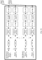
- FIG. 1A and FIG. 1B are a schematic diagram of composition of a receiver frequently used in the current base station.
- the receiver includes two dual-polarized antennas (which support 4R), two power dividers (power splitters), and multiple receive channels (two main receiving channels, two diversity receiving channels, and two inter-frequency channel groups, where each inter-frequency channel group includes N-1 inter-frequency receive channels).
- Each receive channel includes two same filters, a low noise amplifier, a numerical control attenuator, a frequency mixer, an automatic gain control (English: automatic gain control, AGC for short), and an analog-to-digital converter (English: analog-to-digital converter, ADC for short).
- filtering is first performed, by a first filter for the first time, on a radio frequency signal that is received by the dual-polarized antenna; then amplification is performed by the low noise amplifier; then filtering is performed by a second filter for the second time; then attenuation adjustment is performed by the numerical control attenuator; then frequency mixing is performed by the frequency mixer on the radio frequency signal and a local oscillator signal that is output by a local oscillator; then gain adjustment is performed by the AGC; and finally analog-to-digital conversion is performed by the ADC, so that a digital signal is obtained.
- an "R i filter” represents that a passband of the filter is a frequency band R i , where 1 ⁇ i ⁇ N.
- the receiver may support not only an intra-frequency mode (that is, a frequency band of a signal transmitted on the diversity receiving channel is the same as a frequency band of a signal transmitted on the main receiving channel) but also an inter-frequency mode (that is, a frequency band of a signal transmitted on an inter-frequency channel is different from the frequency band of a signal transmitted on the main receiving channel).
- the receiver has the following disadvantages: A quantity of frequency bands supported by the base station is increased by mainly increasing a quantity of receive channels (including a diversity receiving channel and an inter-frequency receive channel) in the receiver; however, a larger quantity of receive channels leads to a larger volume of the receiver, and this is unfavorable to miniaturization of the base station; in addition, costs for deploying multiple receive channels are relatively high.
- CN 101877917 A relates to a remote radio unit which comprises a radio frequency transceiver module, a power amplifier module, an antenna combiner, an optical fiber interface module, a digital intermediate frequency module and a power supply module, wherein the radio frequency transceiver module comprises two independent transmitters and two independent receivers, as well as two radio frequency local oscillation modules which work on A frequency band and B frequency band respectively.
- the power amplifier module comprises a dual-channel wideband power amplifier circuit capable of covering the A frequency band and the B frequency band, as well as two circulators which work on the A frequency band and the B frequency band respectively; and the antenna combiner has the function of a filter of the A frequency band and the B frequency band and the signal combination function and is connected to the two circulators.
- the utilization of the remote radio unit can support double frequency bands and double channels.
- Embodiments of the present invention provide a radio remote unit, a receiver, and a base station, to reduce a quantity of receive channels, so that a volume of a receiver is reduced, a base station is miniaturized, and costs for deploying the receive channels may be reduced.
- the filtering module includes a first order filtering submodule, a low noise amplifier connected to the first order filtering submodule, a second order filtering submodule connected to the low noise amplifier, and a numerical control attenuator connected to the second order filtering submodule;
- a second order filtering submodule on the first receive channel includes a first filter and N second filters, a passband of the first filter is a first frequency band, and all passbands of the N second filters are different from the passband of the first filter;
- a first order filtering submodule on the first receive channel includes filters that are the same as the filters included in the second order filtering submodule on the first receive channel, where N is a positive integer;
- a second order filtering submodule on the second receive channel includes a third filter, and a passband of the third filter is the first frequency band;
- a first order filtering submodule on the second receive channel includes a filter that is the same as the third filter;
- the second order filtering submodule on the first receive channel is a first multiplexer including the first filter and the N second filters
- the first order filtering submodule on the first receive channel is a second multiplexer that is the same as the first multiplexer.
- the second order filtering submodule on the first receive channel includes a combiner, the first filter, and the N second filters, where the first filter and the N second filters are connected to the combiner; and the first order filtering submodule on the first receive channel is a third multiplexer including the filters that are the same as the filters included in the second order filtering submodule on the first receive channel.
- the frequency mixing module on the first receive channel and the frequency mixing module on the second receive channel are frequency mixers; and a digital processing module on the first receive channel and a digital processing module on the second receive channel include an automatic gain control AGC and an analog-to-digital converter ADC that is connected to the AGC.
- the first order filtering submodule on the first receive channel is connected to one interface of a dual-polarized antenna, and the first order filtering submodule on the second receive channel is connected to the other interface of the dual-polarized antenna.
- the at least one receive channel pair includes a first receive channel pair and a second receive channel pair, a first order filtering submodule on a first receive channel in the first receive channel pair is connected to one interface of a dual-polarized antenna, and a first order filtering submodule on a first receive channel in the second receive channel pair is connected to the other interface of the dual-polarized antenna.
- a receiver including the radio remote unit RRU according to any one of the first aspect, or possible implementations of the first aspect of the embodiments of the present invention.
- a base station including the receiver according to the second aspect of the embodiments of the present invention.
- the embodiments of the present invention provide the radio remote unit, the receiver, and the base station.
- the radio remote unit includes the at least one receive channel pair, the first local oscillator module, the second local oscillator module, the local oscillator switching switch, and the controller.
- the RRU uses the controller to control the local oscillator switching switch to perform switching, so that the frequency mixing module on the second receive channel is connected to the first local oscillator module, to support the intra-frequency mode, and a signal, whose frequency band is the same as a frequency band of a signal transmitted on the first receive channel, may be transmitted on the second receive channel; or uses the controller to control the local oscillator switching switch to perform switching, so that the frequency mixing module on the second receive channel is connected to the second local oscillator module, and configure the frequency of the local oscillator signal output by the second local oscillator module as the local oscillator frequency indicated by the inter-frequency mode, to support the inter-frequency mode, so that a signal, whose frequency band is different from a frequency band of a signal transmitted on the first receive channel, may be transmitted on the second receive channel.
- signals in different frequency bands may be transmitted on the second receive channel, and there is no need to deploy a receive channel for a signal in each frequency band. Therefore, the RRU in this embodiment may be used to reduce a quantity of receive channels, so that a volume of a receiver is reduced, and costs for deploying the receive channels are reduced.
- a Global System for Mobile communications (English: Global System for Mobile communications, GSM for short), a Code Division Multiple Access (English: Code Division Multiple Access, CDMA for short) system, a Time Division Multiple Access (English: Time Division Multiple Access, TDMA for short) system, a Wideband Code Division Multiple Access (English: Wideband Code Division Multiple Access Wireless, WCDMA for short) system, a Frequency Division Multiple Access (English: Frequency Division Multiple Addressing, FDMA for short) system, an Orthogonal Frequency Division Multiple Access (English: Orthogonal Frequency-Division Multiple Access, OFDMA for short) system, a single-carrier FDMA (SC-FDMA for short) system, a general packet radio service (English: General Packet Radio Service, GPRS for short) system, a Long Term Evolution (English: Long Term Evolution, LTE for short) system, and other
- a base station in this specification may be a device that is in an access network and that communicates with a wireless terminal over an air interface by using one or more sectors.
- the base station may be configured to mutually convert a received over-the-air frame and an Internet Protocol (English: Internet Protocol, IP for short) packet and serve as a router between the wireless terminal and a remaining portion of the access network, where the remaining portion of the access network may include an IP network.
- the base station may further coordinate attribute management of the air interface.
- the base station may be a base transceiver station (English: Base Transceiver Station, BTS for short) in GSM or CDMA, may be a NodeB (NodeB) in WCDMA, or may be an evolved NodeB (English: evolutional Node B, eNB or e-NodeB for short) in LTE, which is not limited in the present invention.
- BTS Base Transceiver Station
- NodeB NodeB
- WCDMA Wideband Code Division Multiple Access
- evolved NodeB Evolutional Node B, eNB or e-NodeB for short
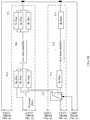
- An embodiment of the present invention provides a radio remote unit (English: Radio Remote Unit, RRU for short), as shown in FIG. 2 , including at least one receive channel pair 11, a first local oscillator module 12, a second local oscillator module 13, a local oscillator switching switch 14, and a controller 15.
- RRU Radio Remote Unit
- Each receive channel pair includes a first receive channel 111 and a second receive channel 112.
- the first receive channel 111 is connected to the first local oscillator module 12
- the second receive channel 112 is connected to the first local oscillator module 12 and the second local oscillator module 13 by using the local oscillator switching switch 14.
- the controller 15 is connected to the second local oscillator module 13 and the local oscillator switching switch 14.
- the controller 15 may be a central processing unit (English: Central Processing Unit, CPU for short), or may be a component or an apparatus having a control function, such as a field-programmable gate array (English: Field-Programmable Gate Array) or an application-specific integrated circuit (English: application specific integrated circuit, ASIC for short).
- the first local oscillator module 12 and the second local oscillator module 13 are configured to output a local oscillator signal, and the first local oscillator module 12 and the second local oscillator module 13 may be local oscillators, or may be other circuits that can generate a local oscillator signal. This is not limited in this embodiment of the present invention.
- each receive channel in each receive channel pair includes a filtering module 01, a frequency mixing module 02 connected to the filtering module 01, and a digital processing module 03 connected to the frequency mixing module 02.
- the filtering module 01 is configured to filter a radio frequency signal that is received by the RRU, and input a filtered signal into the frequency mixing module 02.
- the frequency mixing module 02 is configured to perform frequency mixing on the signal input by the filtering module 01 and a local oscillator signal output by the first local oscillator module 12 or a local oscillator signal output by the second local oscillator module 13, to obtain an intermediate frequency signal.
- the digital processing module 03 is configured to perform digital processing on the intermediate frequency signal that is obtained by the frequency mixing module 02 after frequency mixing, to obtain a digital signal.
- a frequency mixing module 02 on the first receive channel 111 is connected to the first local oscillator module 12, and a frequency mixing module 02 on the second receive channel 112 is connected to the first local oscillator module 12 and the second local oscillator module 13 by using the local oscillator switching switch 14.
- the controller 12 is configured to: receive an operating mode that is sent by a base station; and if the operating mode is an intra-frequency mode, control the local oscillator switching switch 14 to perform switching, so that the frequency mixing module 02 on the second receive channel 112 is connected to the first local oscillator module 12, and therefore the local oscillator signal output by the first local oscillator module 12 may be simultaneously input into the frequency mixing module 02 on the first receive channel 111 and the frequency mixing module 02 on the second receive channel 112; or if the operating mode is an inter-frequency mode, control the local oscillator switching switch 14 to perform switching, so that the frequency mixing module 02 on the second receive channel 112 is connected to the second local oscillator module 13, and configure a frequency of the local oscillator signal output by the second local oscillator module 13 as a local oscillator frequency indicated by the inter-frequency mode, so that the local oscillator signal output by the first local oscillator module 12 may be input into the frequency mixing module 02 on the first receive channel 111, and the local oscillator signal output by the
- a frequency of the local oscillator signal output by the first local oscillator module 12 is different from the frequency of the local oscillator signal output by the second local oscillator module 13, the frequency of the local oscillator signal output by the first local oscillator module 12 may be a fixed frequency, and the frequency of the local oscillator signal output by the second local oscillator module 13 may be configured by the controller 12.
- the RRU provided in this embodiment includes the at least one receive channel pair 11, the first local oscillator module 12, the second local oscillator module 13, the local oscillator switching switch 14, and the controller 15.
- the controller 15 controls the local oscillator switching switch 14 to perform switching, so that the frequency mixing module 02 on the second receive channel 112 is connected to the first local oscillator module 12, to support the intra-frequency mode, and a signal, whose frequency band is the same as a frequency band of a signal transmitted on the first receive channel 111, may be transmitted on the second receive channel 112; or the controller 15 controls the local oscillator switching switch 14 to perform switching, so that the frequency mixing module 02 on the second receive channel 112 is connected to the second local oscillator module 13, and configures the frequency of the local oscillator signal output by the second local oscillator module 13 as the local oscillator frequency indicated by the inter-frequency mode, to support the inter-frequency mode, so that
- signals in different frequency bands may be transmitted on the second receive channel 112, and there is no need to deploy a receive channel for a signal in each frequency band. Therefore, the RRU in this embodiment may be used to reduce a quantity of receive channels, so that a volume of a receiver is reduced, and costs for deploying the receive channels are reduced.
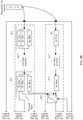
- the filtering module 01 includes a first order filtering submodule 011, a low noise amplifier 012 connected to the first order filtering submodule 011, a second order filtering submodule 013 connected to the low noise amplifier 012, and a numerical control attenuator 014 connected to the second order filtering submodule 013.
- the first order filtering submodule 011 and the second order filtering submodule 013 are configured to perform filtering
- the low noise amplifier 012 is configured to amplify a signal that is filtered by the first order filtering submodule 011
- the numerical control attenuator 014 is configured to perform attenuation adjustment on a signal that is filtered by the second order filtering submodule 013.
- two-order filtering is used in a frequently used receiver.
- the two-order filtering is performed by using the first order filtering submodule 011 and the second order filtering submodule 013.
- a second order filtering submodule 013 on the first receive channel 111 includes a first filter and N second filters, a passband of the first filter is a first frequency band, and all passbands of the N second filters are different from the passband of the first filter, where N is a positive integer.
- An "Ri filter" in FIG. 4A and FIG. 4B represents that a passband of the filter is a frequency band Ri, where 0 ⁇ i ⁇ N.
- the passband of the first filter is a frequency band R0 (that is, the first frequency band is the frequency band R0), and the passbands of the N second filters are respectively a frequency band R1, ..., and RN.
- a first order filtering submodule 011 on the first receive channel 111 includes filters that are the same as the filters included in the second order filtering submodule 013 on the first receive channel 111.
- a second order filtering submodule 013 on the second receive channel 112 includes a third filter, and a passband of the third filter is the first frequency band. As shown in FIG. 4A and FIG. 4B , the passband of the third filter is also the frequency band R0.
- a first order filtering submodule 011 on the second receive channel 112 includes a filter that is the same as the third filter.
- a passband of a filter is a frequency band with minimum attenuation when a signal passes through the filter, that is, a frequency range of a signal that is allowed to pass through the filter.
- the passband of the filter is a frequency band with no attenuation when a signal passes through the filter.
- the first filter, the N second filters, and the third filter may all be band-pass filters.
- the band-pass filter is a device that allows a signal in a specific frequency band to pass through and shields a signal in another frequency band.
- the first filter, the N second filters, and the third filter may also be other circuits that can implement a function of the band-pass filter. This is not limited in this embodiment.
- a filtering module 01 on the second receive channel 112 further includes a 1-out-of-N switch 015, and a numerical control attenuator 014 on the second receive channel 112 is connected to the N second filters and the third filter by using the 1-out-of-N switch 015.
- the controller 15 is connected to the 1-out-of-N switch 015, and is configured to: if the received operating mode sent by the base station is the intra-frequency mode, control the 1-out-of-N switch 015 to perform switching, so that the numerical control attenuator 014 on the second receive channel 112 is connected to the third filter; or if the operating mode is the inter-frequency mode, control the 1-out-of-N switch 015 to perform switching, so that the numerical control attenuator 014 on the second receive channel 112 is connected to a filter, in the N second filters, whose passband is a passband indicated by the inter-frequency mode.
- the controller 15 is further configured to control the 1-out-of-N switch 015 to perform switching, so that the numerical control attenuator 014 on the second receive channel 112 is connected to an R1 filter. If the operating mode sent by the base station is the inter-frequency mode, the inter-frequency mode further indicates the local oscillator frequency and the passband.
- the second order filtering submodule 013 on the first receive channel 111 is a first multiplexer including the first filter and the N second filters, and the first multiplexer includes one input port and N+1 output ports.
- a structure of the first multiplexer is shown in FIG. 5 .
- the first order filtering submodule 011 on the first receive channel 111 is a second multiplexer that is the same as the first multiplexer.
- the second order filtering submodule 013 on the first receive channel 111 includes a combiner, the first filter, and the N second filters, where the first filter and the N second filters are connected to the combiner; and the first order filtering submodule 011 on the first receive channel 111 is a third multiplexer including the filters that are the same as the filters included in the second order filtering submodule 013 on the first receive channel 111.
- a structure of the third multiplexer is the same as the structure of the first multiplexer shown in FIG. 5 .
- the frequency mixing module 02 on the first receive channel 111 and the frequency mixing module 02 on the second receive channel 112 may be frequency mixers; and a digital processing module 03 on the first receive channel 111 and a digital processing module 03 on the second receive channel 112 may include an AGC and an ADC that is connected to the AGC.
- the AGC is configured to perform gain adjustment on a signal on which frequency mixing is performed by the frequency mixer, and the ADC is configured to perform analog-to-digital conversion on a signal on which the gain adjustment is performed, so as to obtain a digital signal.
- the frequency mixing module 02 on the first receive channel 111 and the frequency mixing module on the second receive channel 112 may be other circuits having a frequency mixing function
- the AGC may be another circuit having a gain adjustment function
- the ADC may be another circuit having an analog-to-digital conversion function. This is not limited in this embodiment.
- the first order filtering submodule 01 on the first receive channel 111 may be connected to one interface of a dual-polarized antenna, and the first order filtering submodule 01 on the second receive channel 111 may be connected to the other interface of the dual-polarized antenna.
- the RRU includes one receive channel pair, the RRU is connected to one dual-polarized antenna, and the RRU may support 2R.
- the controller 12 controls the local oscillator switching switch 14 to perform switching, so that the frequency mixing module 02 on the second receive channel 112 is connected to the first local oscillator module 12; and controls the 1-out-of-N switch 015 to perform switching, so that the numerical control attenuator 014 on the second receive channel 112 is connected to the third filter.
- a radio frequency signal received by the dual-polarized antenna is transmitted on two channels.
- filtering is performed by the first filtering module 011 that is on the first receive channel 111
- amplification is performed by a low noise amplifier 012 that is on the first receive channel 111
- filtering is performed by an R0 filter in the second filtering module 013 that is on the first receive channel 111
- attenuation adjustment is performed by a numerical control attenuator 014 that is on the first receive channel 111
- frequency mixing is performed by the frequency mixer 02 that is on the first receive channel 111
- gain adjustment is performed by the AGC that is on the first receive channel 111
- analog-to-digital conversion is performed by the ADC that is on the first receive channel 111, so that a first digital signal is obtained.
- filtering is performed by the first filtering module 011 that is on the second receive channel 112
- amplification is performed by a low noise amplifier 012 that is on the second receive channel 112
- filtering is performed by the second filtering module 013 (the second R0 filter) that is on the second receive channel 112
- attenuation adjustment is performed by the numerical control attenuator 014 that is on the second receive channel 112
- frequency mixing is performed by the frequency mixer 02 that is on the second receive channel 112
- gain adjustment is performed by the AGC that is on the second receive channel 112
- analog-to-digital conversion is performed by the ADC that is on the first receive channel 112, so that a second digital signal is obtained.
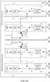
- the controller 12 controls the local oscillator switching switch 14 to perform switching, so that the frequency mixing module 02 on the second receive channel 112 is connected to the second local oscillator module 13, and configures the frequency of the local oscillator signal output by the second local oscillator module 13 as the local oscillator frequency indicated by the inter-frequency mode; and controls the 1-out-of-N switch 015 to perform switching, so that the numerical control attenuator 014 on the second receive channel 112 is connected to the filter (the R1 filter is used as an example for description herein), in the N second filters, whose passband is the passband indicated by the inter-frequency mode.
- a radio frequency signal received by the dual-polarized antenna is transmitted on two channels.
- filtering is performed by an R0 filter in the second filtering module 013 that is on the first receive channel 111
- attenuation adjustment is performed by a numerical control attenuator 014 that is on the first receive channel 111
- frequency mixing is performed by the frequency mixer 02 that is on the first receive channel 111
- gain adjustment is performed by the AGC that is on the first receive channel 111
- analog-to-digital conversion is performed by the ADC that is on the first receive channel 111, so that a first digital signal is obtained.
- filtering is performed by the R1 filter in the second filtering module 013 that is on the first receive channel 111
- attenuation adjustment is performed by the numerical control attenuator 014 that is on the second receive channel 112
- frequency mixing is performed by the frequency mixer 02 that is on the second receive channel 112
- gain adjustment is performed by the AGC that is on the second receive channel 112
- analog-to-digital conversion is performed by the ADC that is on the first receive channel 112, so that a second digital signal is obtained.
- the RRU includes two receive channel pairs, the RRU is connected to two dual-polarized antennas, and the RRU may support 4R.
- a control process of a controller in FIG. 9A and FIG. 9B is similar to a control process of the controller in FIG. 8A and FIG. 8B , and details are not described in this embodiment.
- the RRU may include two receive channel pairs: a first receive channel pair and a second receive channel pair, and the RRU is connected to one dual-polarized antenna.
- a first order filtering submodule 011 on a first receive channel 111 in the first receive channel pair is connected to one interface of the dual-polarized antenna
- a first order filtering submodule 011 on a first receive channel 111 in the second receive channel pair is connected to the other interface of the dual-polarized antenna.
- the RRU supports only the inter-frequency mode
- the controller 15 controls a local oscillator switching switch 14 in each receive channel pair (the first receive channel pair and the second receive channel pair) to perform switching, so that a frequency mixing module 02 on a second receive channel 112 in each receive channel pair is connected to the second local oscillator module 13, and configures the frequency of the local oscillator signal output by the second local oscillator module 13 as the local oscillator frequency indicated by the inter-frequency mode; and controls a 1-out-of-N switch 015 in each receive channel pair to perform switching, so that a numerical control attenuator 014 on the second receive channel 112 is connected to a filter (an R1 filter is used as an example for description herein), in N second filters, whose passband is the passband indicated by the inter-frequency mode.
- a filter an R1 filter is used as an example for description herein
- a radio frequency signal received by the dual-polarized antenna is transmitted on two channels.
- filtering is performed by an R0 filter in a second filtering module 013 that is on the first receive channel 111
- attenuation adjustment is performed by a numerical control attenuator 014 that is on the first receive channel 111
- frequency mixing is performed by a frequency mixer 02 that is on the first receive channel 111
- gain adjustment is performed by an AGC that is on the first receive channel 111
- analog-to-digital conversion is performed by an ADC that is on the first receive channel 111, so that a first digital signal is obtained.
- filtering is performed by an R1 filter in the second filtering module 013 that is on the first receive channel 111
- attenuation adjustment is performed by the numerical control attenuator 014 that is on the second receive channel 112
- frequency mixing is performed by a frequency mixer 02 that is on the second receive channel 112
- gain adjustment is performed by an AGC that is on the second receive channel 112
- analog-to-digital conversion is performed by an ADC that is on the first receive channel 112, so that a second digital signal is obtained.
- the RRU may implement an inter-frequency mode of 4R by connecting to only one dual-polarized antenna. Compared with the connection manner shown in FIG. 9A and FIG. 9B , one dual-polarized antenna may be saved.
- the controller 15 controls the local oscillator switching switch 14 and the 1-out-of-N switch 015 to perform switching, so that the RRU supports not only the intra-frequency mode but also the inter-frequency mode.
- signals in different frequency bands may be transmitted on the second receive channel 112, and there is no need to deploy a receive channel for a signal in each frequency band. Therefore, the RRU in this embodiment may be used to reduce a quantity of receive channels, so that a volume of a receiver is reduced, and costs for deploying the receive channels are reduced.
- the RRU provided in this embodiment may be connected to the dual-polarized antenna without using a power splitter. Therefore, impact on performance of the RRU may be avoided, where the impact is caused because attenuation of a signal is very large due to an allocation loss and an insertion loss of a power splitter.
- An embodiment of the present invention further provides a receiver, as shown in FIG. 11 , including the RRU shown in any one of FIG. 2 , FIG. 4A and FIG. 4B , or FIG. 7A and FIG. 7B to FIG. 10A and FIG. 10B .
- a receiver as shown in FIG. 11 , including the RRU shown in any one of FIG. 2 , FIG. 4A and FIG. 4B , or FIG. 7A and FIG. 7B to FIG. 10A and FIG. 10B .
- the RRU refer to the related descriptions in the foregoing embodiment. Details are not described in this embodiment of the present invention.
- An embodiment of the present invention further provides a base station, as shown in FIG. 12 , including the receiver shown in FIG. 11 .
- a base station as shown in FIG. 12 , including the receiver shown in FIG. 11 .
- RRU Radio Unit
- the disclosed system, apparatus, and method may be implemented in other manners.
- the described apparatus embodiment is merely an example.
- the module or unit division is merely logical function division and may be other division in actual implementation.
- a plurality of units or components may be combined or integrated into another system, or some features may be ignored or not performed.
- the displayed or discussed mutual couplings or direct couplings or communication connections may be implemented by using some interfaces.
- the indirect couplings or communication connections between the apparatuses or units may be implemented in electronic, mechanical, or other forms.
- the units described as separate parts may or may not be physically separate, and parts displayed as units may or may not be physical units, may be located in one position, or may be distributed on a plurality of network units. Some or all of the units may be selected according to actual requirements to achieve the objectives of the solutions of the embodiments.
- functional units in the embodiments of the present invention may be integrated into one processing unit, or each of the units may exist alone physically, or two or more units are integrated into one unit.
- the integrated unit may be implemented in a form of hardware, or may be implemented in a form of a software functional unit.
- the integrated unit When the integrated unit is implemented in the form of a software functional unit and sold or used as an independent product, the integrated unit may be stored in a computer-readable storage medium. Based on such an understanding, the technical solutions of the present invention essentially, or the part contributing to the prior art, or all or a part of the technical solutions may be implemented in the form of a software product.
- the software product is stored in a storage medium and includes several instructions for instructing a computer device (which may be a personal computer, a server, or a network device) or a processor (English: processor) to perform all or a part of the steps of the methods described in the embodiments of the present invention.
- the foregoing storage medium includes: any medium that can store program code, such as a USB flash drive, a removable hard disk, a read-only memory (English: Read-Only Memory, ROM for short), a random access memory (English: Random Access Memory, RAM for short), a magnetic disk, or an optical disc.
- program code such as a USB flash drive, a removable hard disk, a read-only memory (English: Read-Only Memory, ROM for short), a random access memory (English: Random Access Memory, RAM for short), a magnetic disk, or an optical disc.
Landscapes
- Engineering & Computer Science (AREA)
- Computer Networks & Wireless Communication (AREA)
- Signal Processing (AREA)
- Power Engineering (AREA)
- Circuits Of Receivers In General (AREA)
- Transceivers (AREA)
- Superheterodyne Receivers (AREA)
Claims (9)
- Unité radio à distance, RRU, comprenant au moins une paire de canaux de réception (11), un premier module d'oscillateur local (12), un second module d'oscillateur local (13), un commutateur de commutation d'oscillateur local (14) et un dispositif de commande (15), dans laquelle chaque paire de canaux de réception (11) comprend un premier canal de réception (111) et un second canal de réception (112), le premier canal de réception (111) est connecté au premier module d'oscillateur local (12), le second canal de réception (112) est connecté au premier module d'oscillateur local (12) et au second module d'oscillateur local (13) à l'aide du commutateur de commutation d'oscillateur local (14), et le dispositif de commande (15) est connecté au second module d'oscillateur local (13) et au commutateur de commutation d'oscillateur local (14) ;
chaque canal de réception dans chaque paire de canaux de réception (11) comprend un module de filtrage (01), un module de mélange de fréquences (02) connecté au module de filtrage (01), et un module de traitement numérique (03) connecté au module de mélange de fréquences (02), dans laquelle un module de mélange de fréquences (02) sur le premier canal de réception (111) est connecté au premier module d'oscillateur local (12), et un module de mélange de fréquences (02) sur le second canal de réception (112) est connecté au premier module d'oscillateur local (12) et au second module d'oscillateur local (13) à l'aide du commutateur de commutation d'oscillateur local (14) ; et
le dispositif de commande (15) est configuré pour : recevoir un mode de fonctionnement qui est envoyé par une station de base ; et si le mode de fonctionnement est un mode intra-fréquence, commander le commutateur de commutation d'oscillateur local (14) pour réaliser une commutation de sorte que le module de mélange de fréquences (02) sur le second canal de réception (112) est connecté au premier module d'oscillateur local (12); ou si le mode de fonctionnement est un mode inter-fréquence, commander le commutateur de commutation d'oscillateur local (14) pour réaliser une commutation de sorte que le module de mélange de fréquences (02) sur le second canal de réception (112) est connecté au second module d'oscillateur local (13), et pour configurer une fréquence d'un signal d'oscillateur local délivrée par le second module d'oscillateur local (13) en tant que fréquence d'oscillateur local indiquée par le mode inter-fréquence. - RRU selon la revendication 1, dans laquelle le module de filtrage (01) comprend un sous-module de filtrage de premier ordre (011), un amplificateur à faible bruit (012) connecté au sous-module de filtrage de premier ordre (011), un sous-module de filtrage de second ordre (013) connecté à l'amplificateur à faible bruit (012), et un atténuateur à commande numérique (014) connecté au sous-module de filtrage de second ordre (013) ;
un sous-module de filtrage de second ordre (013) sur le premier canal de réception (111) comprend un premier filtre et N deuxièmes filtres, une bande passante du premier filtre est une première bande de fréquences, et toutes les bandes passantes des N deuxièmes filtres sont différentes de la bande passante du premier filtre ; et un sous-module de filtrage de premier ordre (011) sur le premier canal de réception (111) comprend des filtres qui sont les mêmes que les filtres compris dans le sous-module de filtrage de second ordre (013) sur le premier canal de réception (111), dans laquelle N est un nombre entier positif ;
un sous-module de filtrage de second ordre (013) sur le second canal de réception (112) comprend un troisième filtre, et une bande passante du troisième filtre est la première bande de fréquences ; un sous-module de filtrage de premier ordre (011) sur le second canal de réception (112) comprend un filtre qui est le même que le troisième filtre ; un module de filtrage (01) sur le second canal de réception (112) comprend en outre un commutateur 1 parmi N (015) ; et un atténuateur à commande numérique (014) sur le second canal de réception (112) est connecté aux N deuxièmes filtres et au troisième filtre à l'aide du commutateur 1 parmi N (015) ; et
le contrôleur (15) est connecté au commutateur 1 parmi N (015), et est configuré pour : si le mode de fonctionnement est le mode intra-fréquence, commander le commutateur 1 parmi N (015) pour réaliser une commutation de sorte que l'atténuateur à commande numérique (014) sur le second canal de réception (112) est connecté au troisième filtre; ou si le mode de fonctionnement est le mode inter-fréquence, commander le commutateur 1 parmi N (015) pour réaliser une commutation de sorte que l'atténuateur à commande numérique (014) sur le second canal de réception (112) est connecté à un filtre, dans les N deuxièmes filtres, dont la bande passante est une bande passante indiquée par le mode inter-fréquence. - RRU selon la revendication 2, dans laquelle le sous-module de filtrage de second ordre sur le premier canal de réception est un premier multiplexeur comprenant le premier filtre et les N deuxièmes filtres, et le sous-module de filtrage de premier ordre sur le premier canal de réception est un second multiplexeur qui est le même que le premier multiplexeur.
- RRU selon la revendication 2, dans laquelle le sous-module de filtrage de second ordre sur le premier canal de réception comprend un combineur, le premier filtre et les N deuxièmes filtres, dans laquelle le premier filtre et les N deuxièmes filtres sont connectés au combineur ; et le sous-module de filtrage de premier ordre sur le premier canal de réception est un troisième multiplexeur comprenant les filtres qui sont les mêmes que les filtres compris dans le sous-module de filtrage de second ordre sur le premier canal de réception.
- RRU selon l'une quelconque des revendications 2 à 4, dans laquelle le module de mélange de fréquences sur le premier canal de réception et le module de mélange de fréquences sur le second canal de réception sont des mélangeurs de fréquences ; et un module de traitement numérique sur le premier canal de réception et un module de traitement numérique sur le second canal de réception comprennent une commande automatique de gain, CAG, et un convertisseur analogique-numérique, CAN, qui est connecté à la CAG.
- RRU selon la revendication 5, dans laquelle le sous-module de filtrage de premier ordre sur le premier canal de réception est connecté à une interface d'une antenne à double polarisation, et le sous-module de filtrage de premier ordre sur le second canal de réception est connecté à l'autre interface de l'antenne à double polarisation.
- RRU selon la revendication 5, dans laquelle l'au moins une paire de canaux de réception comprend une première paire de canaux de réception et une seconde paire de canaux de réception, un sous-module de filtrage de premier ordre sur un premier canal de réception dans la première paire de canaux de réception est connecté à une interface d'une antenne à double polarisation, et un sous-module de filtrage de premier ordre sur un premier canal de réception dans la seconde paire de canaux de réception est connecté à l'autre interface de l'antenne à double polarisation.
- Récepteur, comprenant l'unité radio à distance, RRU, selon l'une quelconque des revendications 1 à 7.
- Station de base, comprenant le récepteur selon la revendication 8.
Applications Claiming Priority (1)
| Application Number | Priority Date | Filing Date | Title |
|---|---|---|---|
| PCT/CN2015/087674 WO2017028311A1 (fr) | 2015-08-20 | 2015-08-20 | Unité radio à distance, récepteur et station de base |
Publications (3)
| Publication Number | Publication Date |
|---|---|
| EP3324701A1 EP3324701A1 (fr) | 2018-05-23 |
| EP3324701A4 EP3324701A4 (fr) | 2018-07-11 |
| EP3324701B1 true EP3324701B1 (fr) | 2019-10-30 |
Family
ID=58050972
Family Applications (1)
| Application Number | Title | Priority Date | Filing Date |
|---|---|---|---|
| EP15901515.5A Active EP3324701B1 (fr) | 2015-08-20 | 2015-08-20 | Unité radio à distance, récepteur et station de base |
Country Status (6)
| Country | Link |
|---|---|
| US (1) | US10187102B2 (fr) |
| EP (1) | EP3324701B1 (fr) |
| CN (1) | CN106605445B (fr) |
| ES (1) | ES2761581T3 (fr) |
| MX (1) | MX377771B (fr) |
| WO (1) | WO2017028311A1 (fr) |
Families Citing this family (3)
| Publication number | Priority date | Publication date | Assignee | Title |
|---|---|---|---|---|
| CN112400339A (zh) * | 2019-06-03 | 2021-02-23 | 华为技术有限公司 | 一种无线通信装置及载波切换方法 |
| CN111884666A (zh) * | 2020-07-07 | 2020-11-03 | 西安欣创电子技术有限公司 | 一种采用锁相环复用的多模多通道射频接收机芯片 |
| US12355478B2 (en) * | 2021-01-27 | 2025-07-08 | The Boeing Company | Programmable RF front end for wideband ADC-based receiver |
Family Cites Families (18)
| Publication number | Priority date | Publication date | Assignee | Title |
|---|---|---|---|---|
| CN2733753Y (zh) | 2004-08-20 | 2005-10-12 | 南京东大宽带通信技术有限公司 | 数字中频多频多模射频模块 |
| US7796956B2 (en) | 2005-05-03 | 2010-09-14 | Telefonaktiebolaget L M Ericsson (Publ) | Receiver for a multi-antenna, multi-band radio |
| GB0905820D0 (en) * | 2009-04-03 | 2009-05-20 | Bae Systems Plc | Improvements relating to signal processing |
| CN101877917B (zh) * | 2009-04-28 | 2012-09-05 | 电信科学技术研究院 | 射频拉远单元 |
| CN101908896B (zh) | 2009-06-03 | 2013-04-24 | 中国科学院微电子研究所 | 一种多频段射频接收机 |
| CN101742671B (zh) * | 2009-12-11 | 2013-01-30 | 泉州市迈韦通信技术有限公司 | 一种具有载波调度功能的无线数字直放站和实现载波调度的方法 |
| CN102096079B (zh) | 2009-12-12 | 2013-12-11 | 杭州中科微电子有限公司 | 一种多模式多频段卫星导航接收机射频前端构成方法及其模块 |
| CN101841345B (zh) * | 2010-04-15 | 2013-12-11 | 新邮通信设备有限公司 | 一种时分双工射频拉远单元 |
| CN101938293B (zh) * | 2010-08-17 | 2013-01-02 | 北京天碁科技有限公司 | 一种支持多模的射频收发信装置、终端及终端的切换方法 |
| CN101980580B (zh) * | 2010-11-29 | 2013-04-10 | 大唐移动通信设备有限公司 | 一种基站、远端射频单元及其信号发送方法 |
| WO2012100372A1 (fr) * | 2011-01-27 | 2012-08-02 | Telefonaktiebolaget L M Ericsson (Publ) | Procédé permettant le contournement d'unités radio distantes (rru) dans un réseau de communication sans fil et dispositif d'unité rru |
| US8582478B2 (en) | 2011-03-23 | 2013-11-12 | Qualcomm, Incorporated | Single antenna, multi-band frequency division multiplexed mobile communication |
| KR102180573B1 (ko) * | 2013-10-22 | 2020-11-18 | 삼성전자주식회사 | 신호를 수신하는 방법 및 전자 장치 |
| DE102014206311B3 (de) * | 2014-04-02 | 2015-10-08 | Siemens Aktiengesellschaft | Empfangssystem für Lokalspulen eines Magnetresonanztomographiesystems |
| CN203933539U (zh) | 2014-05-30 | 2014-11-05 | 深圳贝特莱电子科技有限公司 | 低噪声放大器及gnss系统多模接收机前端的射频系统 |
| DE102014108774A1 (de) * | 2014-06-24 | 2016-01-07 | Intel IP Corporation | Vorrichtung und Verfahren zum Erzeugen eines Oszillatorsignals |
| DE102014114044B4 (de) * | 2014-09-26 | 2024-02-29 | Intel Corporation | Eine Vorrichtung und ein Verfahren zum Erzeugen von Basisbandempfangssignalen |
| DE102015104672B4 (de) * | 2015-03-26 | 2025-11-06 | Apple Inc. | Eine Vorrichtung und ein Verfahren zum Bereitstellen von Oszillatorsignalen sowie ein maschinenlesbares Speichermedium zu dessen Ausführung und Sender |
-
2015
- 2015-08-20 CN CN201580046720.4A patent/CN106605445B/zh active Active
- 2015-08-20 WO PCT/CN2015/087674 patent/WO2017028311A1/fr not_active Ceased
- 2015-08-20 MX MX2018001911A patent/MX377771B/es active IP Right Grant
- 2015-08-20 EP EP15901515.5A patent/EP3324701B1/fr active Active
- 2015-08-20 ES ES15901515T patent/ES2761581T3/es active Active
-
2018
- 2018-02-14 US US15/897,046 patent/US10187102B2/en active Active
Non-Patent Citations (1)
| Title |
|---|
| None * |
Also Published As
| Publication number | Publication date |
|---|---|
| EP3324701A1 (fr) | 2018-05-23 |
| US10187102B2 (en) | 2019-01-22 |
| MX2018001911A (es) | 2018-06-19 |
| BR112018002900A2 (pt) | 2018-09-18 |
| CN106605445A (zh) | 2017-04-26 |
| CN106605445B (zh) | 2019-12-13 |
| ES2761581T3 (es) | 2020-05-20 |
| WO2017028311A1 (fr) | 2017-02-23 |
| EP3324701A4 (fr) | 2018-07-11 |
| US20180175897A1 (en) | 2018-06-21 |
| MX377771B (es) | 2025-03-11 |
Similar Documents
| Publication | Publication Date | Title |
|---|---|---|
| US9154171B2 (en) | Reconfigurable radio frequency circuits and methods of receiving | |
| US11075666B2 (en) | Radio frequency transmit-receive apparatus, terminal, and method | |
| EP3512111B1 (fr) | Procédé et dispositif de prise en charge de coexistence de multiples bandes dans un module de fréquence radio | |
| KR101803342B1 (ko) | 무선 네트워크에서 운용되는 다중대역 라디오 장치 및 방법 | |
| EP3099138B1 (fr) | Terminal sans fil multimode | |
| US10015701B2 (en) | Multimode dual-path terminal | |
| RU2543515C2 (ru) | Способ, устройство и система передачи сигнала связи | |
| US9258050B2 (en) | Transceiving module, antenna, base station and signal receiving method | |
| US10187102B2 (en) | Radio remote unit, receiver, and base station | |
| CN104854795B (zh) | 宽带信号接收的方法、装置、射频处理单元和宽带天线 | |
| EP4231525A1 (fr) | Unité radiofréquence, antenne et procédé de traitement de signal | |
| US11601145B2 (en) | Tunable antenna and communications terminal | |
| BR112018002900B1 (pt) | Unidade remota de rádio, receptor e estação de base | |
| EP3407651A1 (fr) | Procédé et appareil de commande de mode pour un terminal multimode, et terminal multimode | |
| TWM480215U (zh) | 具有多頻寬之轉發器 |
Legal Events
| Date | Code | Title | Description |
|---|---|---|---|
| STAA | Information on the status of an ep patent application or granted ep patent |
Free format text: STATUS: THE INTERNATIONAL PUBLICATION HAS BEEN MADE |
|
| PUAI | Public reference made under article 153(3) epc to a published international application that has entered the european phase |
Free format text: ORIGINAL CODE: 0009012 |
|
| STAA | Information on the status of an ep patent application or granted ep patent |
Free format text: STATUS: REQUEST FOR EXAMINATION WAS MADE |
|
| 17P | Request for examination filed |
Effective date: 20180215 |
|
| AK | Designated contracting states |
Kind code of ref document: A1 Designated state(s): AL AT BE BG CH CY CZ DE DK EE ES FI FR GB GR HR HU IE IS IT LI LT LU LV MC MK MT NL NO PL PT RO RS SE SI SK SM TR |
|
| AX | Request for extension of the european patent |
Extension state: BA ME |
|
| A4 | Supplementary search report drawn up and despatched |
Effective date: 20180613 |
|
| RIC1 | Information provided on ipc code assigned before grant |
Ipc: H04W 88/08 20090101AFI20180605BHEP Ipc: H04B 1/00 20060101ALI20180605BHEP |
|
| DAV | Request for validation of the european patent (deleted) | ||
| DAX | Request for extension of the european patent (deleted) | ||
| RIC1 | Information provided on ipc code assigned before grant |
Ipc: H04W 88/08 20090101AFI20190306BHEP Ipc: H04B 1/00 20060101ALI20190306BHEP |
|
| GRAP | Despatch of communication of intention to grant a patent |
Free format text: ORIGINAL CODE: EPIDOSNIGR1 |
|
| STAA | Information on the status of an ep patent application or granted ep patent |
Free format text: STATUS: GRANT OF PATENT IS INTENDED |
|
| INTG | Intention to grant announced |
Effective date: 20190509 |
|
| GRAS | Grant fee paid |
Free format text: ORIGINAL CODE: EPIDOSNIGR3 |
|
| GRAA | (expected) grant |
Free format text: ORIGINAL CODE: 0009210 |
|
| STAA | Information on the status of an ep patent application or granted ep patent |
Free format text: STATUS: THE PATENT HAS BEEN GRANTED |
|
| AK | Designated contracting states |
Kind code of ref document: B1 Designated state(s): AL AT BE BG CH CY CZ DE DK EE ES FI FR GB GR HR HU IE IS IT LI LT LU LV MC MK MT NL NO PL PT RO RS SE SI SK SM TR |
|
| REG | Reference to a national code |
Ref country code: GB Ref legal event code: FG4D |
|
| REG | Reference to a national code |
Ref country code: CH Ref legal event code: EP |
|
| REG | Reference to a national code |
Ref country code: DE Ref legal event code: R096 Ref document number: 602015040917 Country of ref document: DE |
|
| REG | Reference to a national code |
Ref country code: AT Ref legal event code: REF Ref document number: 1197491 Country of ref document: AT Kind code of ref document: T Effective date: 20191115 |
|
| REG | Reference to a national code |
Ref country code: IE Ref legal event code: FG4D |
|
| REG | Reference to a national code |
Ref country code: LT Ref legal event code: MG4D |
|
| PG25 | Lapsed in a contracting state [announced via postgrant information from national office to epo] |
Ref country code: LV Free format text: LAPSE BECAUSE OF FAILURE TO SUBMIT A TRANSLATION OF THE DESCRIPTION OR TO PAY THE FEE WITHIN THE PRESCRIBED TIME-LIMIT Effective date: 20191030 Ref country code: NL Free format text: LAPSE BECAUSE OF FAILURE TO SUBMIT A TRANSLATION OF THE DESCRIPTION OR TO PAY THE FEE WITHIN THE PRESCRIBED TIME-LIMIT Effective date: 20191030 Ref country code: SE Free format text: LAPSE BECAUSE OF FAILURE TO SUBMIT A TRANSLATION OF THE DESCRIPTION OR TO PAY THE FEE WITHIN THE PRESCRIBED TIME-LIMIT Effective date: 20191030 Ref country code: LT Free format text: LAPSE BECAUSE OF FAILURE TO SUBMIT A TRANSLATION OF THE DESCRIPTION OR TO PAY THE FEE WITHIN THE PRESCRIBED TIME-LIMIT Effective date: 20191030 Ref country code: NO Free format text: LAPSE BECAUSE OF FAILURE TO SUBMIT A TRANSLATION OF THE DESCRIPTION OR TO PAY THE FEE WITHIN THE PRESCRIBED TIME-LIMIT Effective date: 20200130 Ref country code: PL Free format text: LAPSE BECAUSE OF FAILURE TO SUBMIT A TRANSLATION OF THE DESCRIPTION OR TO PAY THE FEE WITHIN THE PRESCRIBED TIME-LIMIT Effective date: 20191030 Ref country code: GR Free format text: LAPSE BECAUSE OF FAILURE TO SUBMIT A TRANSLATION OF THE DESCRIPTION OR TO PAY THE FEE WITHIN THE PRESCRIBED TIME-LIMIT Effective date: 20200131 Ref country code: FI Free format text: LAPSE BECAUSE OF FAILURE TO SUBMIT A TRANSLATION OF THE DESCRIPTION OR TO PAY THE FEE WITHIN THE PRESCRIBED TIME-LIMIT Effective date: 20191030 Ref country code: BG Free format text: LAPSE BECAUSE OF FAILURE TO SUBMIT A TRANSLATION OF THE DESCRIPTION OR TO PAY THE FEE WITHIN THE PRESCRIBED TIME-LIMIT Effective date: 20200130 Ref country code: PT Free format text: LAPSE BECAUSE OF FAILURE TO SUBMIT A TRANSLATION OF THE DESCRIPTION OR TO PAY THE FEE WITHIN THE PRESCRIBED TIME-LIMIT Effective date: 20200302 |
|
| REG | Reference to a national code |
Ref country code: NL Ref legal event code: MP Effective date: 20191030 |
|
| REG | Reference to a national code |
Ref country code: ES Ref legal event code: FG2A Ref document number: 2761581 Country of ref document: ES Kind code of ref document: T3 Effective date: 20200520 |
|
| PG25 | Lapsed in a contracting state [announced via postgrant information from national office to epo] |
Ref country code: HR Free format text: LAPSE BECAUSE OF FAILURE TO SUBMIT A TRANSLATION OF THE DESCRIPTION OR TO PAY THE FEE WITHIN THE PRESCRIBED TIME-LIMIT Effective date: 20191030 Ref country code: RS Free format text: LAPSE BECAUSE OF FAILURE TO SUBMIT A TRANSLATION OF THE DESCRIPTION OR TO PAY THE FEE WITHIN THE PRESCRIBED TIME-LIMIT Effective date: 20191030 Ref country code: IS Free format text: LAPSE BECAUSE OF FAILURE TO SUBMIT A TRANSLATION OF THE DESCRIPTION OR TO PAY THE FEE WITHIN THE PRESCRIBED TIME-LIMIT Effective date: 20200229 |
|
| PG25 | Lapsed in a contracting state [announced via postgrant information from national office to epo] |
Ref country code: AL Free format text: LAPSE BECAUSE OF FAILURE TO SUBMIT A TRANSLATION OF THE DESCRIPTION OR TO PAY THE FEE WITHIN THE PRESCRIBED TIME-LIMIT Effective date: 20191030 |
|
| PG25 | Lapsed in a contracting state [announced via postgrant information from national office to epo] |
Ref country code: CZ Free format text: LAPSE BECAUSE OF FAILURE TO SUBMIT A TRANSLATION OF THE DESCRIPTION OR TO PAY THE FEE WITHIN THE PRESCRIBED TIME-LIMIT Effective date: 20191030 Ref country code: RO Free format text: LAPSE BECAUSE OF FAILURE TO SUBMIT A TRANSLATION OF THE DESCRIPTION OR TO PAY THE FEE WITHIN THE PRESCRIBED TIME-LIMIT Effective date: 20191030 Ref country code: EE Free format text: LAPSE BECAUSE OF FAILURE TO SUBMIT A TRANSLATION OF THE DESCRIPTION OR TO PAY THE FEE WITHIN THE PRESCRIBED TIME-LIMIT Effective date: 20191030 Ref country code: DK Free format text: LAPSE BECAUSE OF FAILURE TO SUBMIT A TRANSLATION OF THE DESCRIPTION OR TO PAY THE FEE WITHIN THE PRESCRIBED TIME-LIMIT Effective date: 20191030 |
|
| REG | Reference to a national code |
Ref country code: DE Ref legal event code: R097 Ref document number: 602015040917 Country of ref document: DE |
|
| REG | Reference to a national code |
Ref country code: AT Ref legal event code: MK05 Ref document number: 1197491 Country of ref document: AT Kind code of ref document: T Effective date: 20191030 |
|
| PG25 | Lapsed in a contracting state [announced via postgrant information from national office to epo] |
Ref country code: SK Free format text: LAPSE BECAUSE OF FAILURE TO SUBMIT A TRANSLATION OF THE DESCRIPTION OR TO PAY THE FEE WITHIN THE PRESCRIBED TIME-LIMIT Effective date: 20191030 Ref country code: IT Free format text: LAPSE BECAUSE OF FAILURE TO SUBMIT A TRANSLATION OF THE DESCRIPTION OR TO PAY THE FEE WITHIN THE PRESCRIBED TIME-LIMIT Effective date: 20191030 Ref country code: SM Free format text: LAPSE BECAUSE OF FAILURE TO SUBMIT A TRANSLATION OF THE DESCRIPTION OR TO PAY THE FEE WITHIN THE PRESCRIBED TIME-LIMIT Effective date: 20191030 |
|
| PLBE | No opposition filed within time limit |
Free format text: ORIGINAL CODE: 0009261 |
|
| STAA | Information on the status of an ep patent application or granted ep patent |
Free format text: STATUS: NO OPPOSITION FILED WITHIN TIME LIMIT |
|
| 26N | No opposition filed |
Effective date: 20200731 |
|
| PG25 | Lapsed in a contracting state [announced via postgrant information from national office to epo] |
Ref country code: SI Free format text: LAPSE BECAUSE OF FAILURE TO SUBMIT A TRANSLATION OF THE DESCRIPTION OR TO PAY THE FEE WITHIN THE PRESCRIBED TIME-LIMIT Effective date: 20191030 Ref country code: AT Free format text: LAPSE BECAUSE OF FAILURE TO SUBMIT A TRANSLATION OF THE DESCRIPTION OR TO PAY THE FEE WITHIN THE PRESCRIBED TIME-LIMIT Effective date: 20191030 |
|
| PG25 | Lapsed in a contracting state [announced via postgrant information from national office to epo] |
Ref country code: MC Free format text: LAPSE BECAUSE OF FAILURE TO SUBMIT A TRANSLATION OF THE DESCRIPTION OR TO PAY THE FEE WITHIN THE PRESCRIBED TIME-LIMIT Effective date: 20191030 |
|
| REG | Reference to a national code |
Ref country code: CH Ref legal event code: PL |
|
| GBPC | Gb: european patent ceased through non-payment of renewal fee |
Effective date: 20200820 |
|
| PG25 | Lapsed in a contracting state [announced via postgrant information from national office to epo] |
Ref country code: CH Free format text: LAPSE BECAUSE OF NON-PAYMENT OF DUE FEES Effective date: 20200831 Ref country code: LI Free format text: LAPSE BECAUSE OF NON-PAYMENT OF DUE FEES Effective date: 20200831 Ref country code: LU Free format text: LAPSE BECAUSE OF NON-PAYMENT OF DUE FEES Effective date: 20200820 |
|
| REG | Reference to a national code |
Ref country code: BE Ref legal event code: MM Effective date: 20200831 |
|
| PG25 | Lapsed in a contracting state [announced via postgrant information from national office to epo] |
Ref country code: FR Free format text: LAPSE BECAUSE OF NON-PAYMENT OF DUE FEES Effective date: 20200831 |
|
| PG25 | Lapsed in a contracting state [announced via postgrant information from national office to epo] |
Ref country code: IE Free format text: LAPSE BECAUSE OF NON-PAYMENT OF DUE FEES Effective date: 20200820 Ref country code: GB Free format text: LAPSE BECAUSE OF NON-PAYMENT OF DUE FEES Effective date: 20200820 Ref country code: BE Free format text: LAPSE BECAUSE OF NON-PAYMENT OF DUE FEES Effective date: 20200831 |
|
| PG25 | Lapsed in a contracting state [announced via postgrant information from national office to epo] |
Ref country code: TR Free format text: LAPSE BECAUSE OF FAILURE TO SUBMIT A TRANSLATION OF THE DESCRIPTION OR TO PAY THE FEE WITHIN THE PRESCRIBED TIME-LIMIT Effective date: 20191030 Ref country code: MT Free format text: LAPSE BECAUSE OF FAILURE TO SUBMIT A TRANSLATION OF THE DESCRIPTION OR TO PAY THE FEE WITHIN THE PRESCRIBED TIME-LIMIT Effective date: 20191030 Ref country code: CY Free format text: LAPSE BECAUSE OF FAILURE TO SUBMIT A TRANSLATION OF THE DESCRIPTION OR TO PAY THE FEE WITHIN THE PRESCRIBED TIME-LIMIT Effective date: 20191030 |
|
| PG25 | Lapsed in a contracting state [announced via postgrant information from national office to epo] |
Ref country code: MK Free format text: LAPSE BECAUSE OF FAILURE TO SUBMIT A TRANSLATION OF THE DESCRIPTION OR TO PAY THE FEE WITHIN THE PRESCRIBED TIME-LIMIT Effective date: 20191030 |
|
| P01 | Opt-out of the competence of the unified patent court (upc) registered |
Effective date: 20230524 |
|
| PGFP | Annual fee paid to national office [announced via postgrant information from national office to epo] |
Ref country code: ES Payment date: 20250903 Year of fee payment: 11 |
|
| PGFP | Annual fee paid to national office [announced via postgrant information from national office to epo] |
Ref country code: DE Payment date: 20250702 Year of fee payment: 11 |