EP3324716A2 - System zur kühlung von wärmeerzeugenden elektronischen bauteilen - Google Patents
System zur kühlung von wärmeerzeugenden elektronischen bauteilen Download PDFInfo
- Publication number
- EP3324716A2 EP3324716A2 EP17196858.9A EP17196858A EP3324716A2 EP 3324716 A2 EP3324716 A2 EP 3324716A2 EP 17196858 A EP17196858 A EP 17196858A EP 3324716 A2 EP3324716 A2 EP 3324716A2
- Authority
- EP
- European Patent Office
- Prior art keywords
- heat
- fluid
- exchanger
- semi
- cooling
- Prior art date
- Legal status (The legal status is an assumption and is not a legal conclusion. Google has not performed a legal analysis and makes no representation as to the accuracy of the status listed.)
- Granted
Links
Images


Classifications
-
- H—ELECTRICITY
- H05—ELECTRIC TECHNIQUES NOT OTHERWISE PROVIDED FOR
- H05K—PRINTED CIRCUITS; CASINGS OR CONSTRUCTIONAL DETAILS OF ELECTRIC APPARATUS; MANUFACTURE OF ASSEMBLAGES OF ELECTRICAL COMPONENTS
- H05K7/00—Constructional details common to different types of electric apparatus
- H05K7/20—Modifications to facilitate cooling, ventilating, or heating
- H05K7/20709—Modifications to facilitate cooling, ventilating, or heating for server racks or cabinets; for data centers, e.g. 19-inch computer racks
- H05K7/208—Liquid cooling with phase change
- H05K7/20818—Liquid cooling with phase change within cabinets for removing heat from server blades
-
- H—ELECTRICITY
- H05—ELECTRIC TECHNIQUES NOT OTHERWISE PROVIDED FOR
- H05K—PRINTED CIRCUITS; CASINGS OR CONSTRUCTIONAL DETAILS OF ELECTRIC APPARATUS; MANUFACTURE OF ASSEMBLAGES OF ELECTRICAL COMPONENTS
- H05K7/00—Constructional details common to different types of electric apparatus
- H05K7/20—Modifications to facilitate cooling, ventilating, or heating
- H05K7/20709—Modifications to facilitate cooling, ventilating, or heating for server racks or cabinets; for data centers, e.g. 19-inch computer racks
- H05K7/208—Liquid cooling with phase change
- H05K7/20827—Liquid cooling with phase change within rooms for removing heat from cabinets, e.g. air conditioning devices
Definitions
- the present invention relates to a system of cooling of heat-producing elements, more particularly electronic components contained in metal cabinets or racks, in order to dissipate the heat generated by the racks directly to the exterior without the use of refrigeration systems and/or of pumps for circulation of the cooling fluid or other machines so as to minimise the energy input while performing efficient cooling.
- the present invention relates to a system of cooling suitable for removing heat from said electronic elements, maintaining them at a temperature around 60°C or below, transferring said heat directly to the exterior of the closed room containing said electronic components.
- Electronic units are made up of an assembly of metal cabinets, known as racks, where each of which houses a plurality of electronic boards placed in pull-out drawers, whose components release heat and have to be cooled in order to be able to operate at their optimal design temperature, generally equal to or lower than 60°C.
- the cooling in these metal cabinets is performed by using finned metal heat sinks, placed in contact with the elements to be cooled, or with other more efficient systems such as for example those that use heat pipes.
- the air of the room containing said racks has to be maintained at a sufficiently low temperature in order to allow cooling of the aforementioned heat sinks in order ultimately to contain the temperature of said electronic elements.
- the air of the room in which said racks are contained is maintained at the necessary temperature with air conditioning systems inside the room, which are fed by refrigeration units taking up large quantities of electrical energy and requiring constant maintenance.
- cooling of the electronic component or board is performed in a simple manner, using a "heat pipe” (hereinafter referred to as TdC) which can be used thanks to the higher temperature at which the electronic components of the latest generations can work, generally around 60°C.
- TdC heat pipe
- the heat pipe is a closed pipe having a system of heat exchange which can transport large quantities of heat with a very small difference in temperature between the hot and cold interfaces, and which functions on the principle of thermal conductivity and phase transition, transferring heat between two solid interfaces.
- the heat pipe which references the natural cycle of the evaporation of the water forced by solar heating, transfers the heat from a hot source (i.e. electronic components which work generally at 60°C) to a cooling means via the change of state from liquid to vapour of a low boiling fluid circulating inside a closed circuit, and the successive condensation inside this closed circuit, without the use of mechanical work: the cooling fluids for air conditioning and refrigeration can be used in the abovementioned heat pipe.
- the heat pipes exploit the principle of evaporation and condensation of a gas in a closed pipe, with the effect of absorbing heat in the evaporation phase and yielding it during the condensation, where circulation of the fluid inside the pipes is due to the difference in temperature between evaporator and condenser which causes the movement of the vapour towards the coldest point.
- the heat which is captured by the cold plate passes to a cooling fluid (e.g. water) using a jump in temperature to the detriment of that existing between the heat source and the disposal means.
- a cooling fluid e.g. water
- the fluid moved by a pump transports the heat to any heat sink placed outside which releases the heat to the surrounding air.
- the aim is to cool the fluid to a lower temperature with the use of refrigerants in order to regain the efficiency lost in the transmission of the heat.
- the heat is transported to a finned or ventilated exchanger, placed in the rack of the electronic boards and the heat is transferred to the room air which is in turn cooled by compressor air conditioning systems.
- the known heat pipe is used only for transferring locally the heat from the electronic components to an air heat sink which is inside the rack or to cold plates with an intermediate heat exchange.
- Said heat pipe has never been used to dissipate directly outdoors the heat generated by the racks, due to the high number of electronic elements to be cooled present in a drawer of a rack, which should provide a manual cut-off valve or tap on each heat pipe but in practice there are no sufficient physical spaces for housing the necessary quantity of taps.
- the object of the present invention is that of overcoming the disadvantages of the prior art by providing a cooling system of metal cabinets or racks placed inside a room, and of the heat-producing metal elements contained therein, which requires conditioning systems having considerably smaller size with respect to those known so as to use smaller quantities of electrical energy.
- a further object is that of providing such a cooling system which does not entail the transfer of the heat from the electronic elements to the room wherein the racks are contained but instead entails to transport the heat, and dissipate it, directly outdoors without the use of refrigeration systems which absorb large quantities of electrical energy, and limit the electrical energy to the minimum necessary for actuation of the fans.
- Yet another object of the invention is that of providing such a system which is also simple and economical to produce and also to manage.
- the object of the present invention relates to a system for dissipating directly to the exterior (outdoors) the heat generated by one or more racks placed inside a room, where the heat pipes associated with the electronic elements in the drawers of the racks (internal circuits) transfer the heat directly to the outside of the room by means of one or more circuits of cooling fluid (external general circuit) which act as heat pipes, so as not to require electrical energy for the transport of the cooling fluid.
- cooling fluid external general circuit
- the present system of cooling semiconductors of electronic components contained in drawers of metal cabinets or racks which are placed inside a room comprises:
- the system provides for the use of a particular exchanger constituted by two semi-exchangers in contact one with the other but easily detachable and with fluid circuits independent one from the other, wherein the first semi-exchanger transmits the heat, which has been subtracted from elements to be cooled, to the second semi-exchanger through simple conductive contact and temperature difference, where at least one of said semi-exchangers is a phase transition exchanger (two-phase).
- the Applicant has in fact found that it is possible to use an exchanger with separable sections in the cooling of each source of heat, for example semiconductor elements or the like, said exchanger generating a positive difference of temperature with respect to the dissipation means, normally represented by the outside air, even if it is possible to provide alternative solutions of dissipation as indicated here below in detail, and with the need for separation of the single elements from the central plant without loss of coolant.
- the system that constitutes the first object of the present invention does not provide for the use of pumps for circulation of the fluid which cools the electronic components of the computers and even less of coolers with compressor, so as to minimise the energy input while performing efficient cooling.
- the cooling system comprises at least two heat exchange elements, or semi-exchangers as defined above, which equate to two separate loop heat pipes, which are placed in contact one with the other at a respective sink plate, yet detachable and hydraulically independent one from the other, operating in different ranges of temperatures, wherein at least one of the two semi-exchangers is a primary semi-exchanger associated with at least one container, generally a drawer of a rack, placed in a server room, generally closed, in order to cool one or more electronic components (e.g.
- said drawer in such a way as to transfer the dissipation heat of said drawer to a secondary semi-exchanger, said secondary semi-exchanger being placed inside said room in order to transfer to the outside environment the heat exchanged with a least said primary semi-exchanger, so as to subtract from said room the heat generated by said electronic components contained in said drawer of said rack.
- each of the two circuits shows a loop heat pipe and the two circuits exchange heat between each other by means of conduction thanks to the plates of the two semi-exchangers which are in contact one with the other.
- Drawer here is intended to identify a container, mostly with parallelepiped shape, which houses electronic components mounted on one or more electronic boards.
- the heat that said secondary semi-exchanger has subtracted from the first semi-exchanger can be transported and dissipated directly to the exterior in various ways so as to subtract it from the room containing said racks, where the exterior is not always represented by the air but can also be represented, for example, by a certain flow of water which cools a plate or tube bundle condenser.
- the condenser does not release heat towards the environment but transfers it instead to the water
- said condenser can also be installed inside the room which houses the racks: the cooling water will enter at a certain temperature and will exit at a higher temperature and will then be dispersed outside (dispersion of heat).
- the same condenser can be cooled by water which will go to disperse heat in an external cooling tower, by means of partial evaporation of the water itself (adiabatic cooling). All this takes place in closed circuit, with constant reintegration of the water lost through evaporation.
- the system for removing heat in a second embodiment and third embodiment of the present invention provides for the exchange of heat between interior-exterior to take place by using exclusively the system known as "heat pipe”, both in its more simple “monopipe” version (third embodiment) and in the more efficient “loop” version (second embodiment) without the use of semi-exchangers in thermally conductive contact one with the other.
- a "heat pipe” is a closed circuit 1, generally loop, which absorbs heat from a hot source 2 (e.g. heat sink plate in copper or aluminium on which the electronic component is generally mounted whose working temperature must not exceed a certain value).
- a hot source 2 e.g. heat sink plate in copper or aluminium on which the electronic component is generally mounted whose working temperature must not exceed a certain value.
- a cooling fluid 3 circulates which is then transformed into vapour 4 thanks to the heat coming from said source 2 dissipating heat: said vapour 4 moves towards the colder area 5 of the circuit 1, defined here also as compensation or plenum chamber, where it will condense, transforming again into the cooling liquid 3 without the use of mechanical work.
- the present cooling system comprises at least one primary semi-exchanger 12 intended to cool one or more drawers 11 contained in a rack 10 (i.e. container cabinet of drawers) which is placed in a room 50 of servers - databases, generally closed, said primary semi-exchanger 12 being intended to remove the heat generated by said drawer 11 in order to maintain a predetermined temperature in said drawer; a secondary semi-exchanger 120 in contact with one or more of said primary semi-exchangers 12 of said drawers 11 of said rack 10, said secondary semi-exchanger 120 being intended to transfer to the outside the heat transmitted by said primary semi-exchangers 12 by means of the sink plates.
- a rack 10 i.e. container cabinet of drawers
- a secondary semi-exchanger 120 in contact with one or more of said primary semi-exchangers 12 of said drawers 11 of said rack 10, said secondary semi-exchanger 120 being intended to transfer to the outside the heat transmitted by said primary semi-exchangers 12 by means of the sink plates.
- the face 20 of the primary semi-exchanger 12 is connected, together with others (but always in an independent manner), to the face 20 of the larger secondary semi-exchanger 120 which receives the heat of all the drawers of a single rack, which then connects to the general dissipation plant 100 as will be illustrated in detail here below.
- the primary semi-exchanger 12 includes a line 13 wherein the cooling liquid circulates and a line 14 wherein the vapour of said cooling liquid circulates, said fluid lines 13, 14 being in fluid communication one with the other to form a closed circuit, said primary semi-exchanger being a phase transition exchanger.
- the secondary semi-exchanger 120 is preferably also a phase transition exchanger and provides a line 13 wherein a cooling liquid circulates and a line 14 wherein the vapour of said cooling liquid circulates.
- a first cooling fluid circulates and in the secondary semi-exchanger 120 a second cooling fluid circulates, said primary and secondary fluids being able to be identical or different one from the other, yet operating with a different temperature range.
- Said secondary semi-exchanger 120 in addition to being in contact with one or more primary semi-exchangers 12, is associated with a dissipation system of the heat deriving from the condensation of the secondary fluid in the secondary semi-exchanger 120: said system can be for example at least one dry cooler 100, static or ventilated, placed outside the room 50 so as to transmit directly to the outside environment (outdoors) the heat of dissipation of the rack 10, subtracting said heat from the environment of the room 50 in which the racks 11 are housed.
- said system can be for example at least one dry cooler 100, static or ventilated, placed outside the room 50 so as to transmit directly to the outside environment (outdoors) the heat of dissipation of the rack 10, subtracting said heat from the environment of the room 50 in which the racks 11 are housed.
- Dry coolers here are intended to identify air heat sinks equipped with fans, designed to cool a liquid, in the present case the cooling liquid of the secondary semi-exchanger 120 using outside air.
- part of the circuit formed by said fluid lines 13, 14 of said secondary semi-exchanger 120 converges outside of said room 50, preferably in an outside air dry cooler 100, even if this is not binding for the purpose of the present invention.
- Said fluid lines 13, 14 of said secondary semi-exchanger 120 provide, each,a pair of respective cut-off valves 70, 71 in order to allow any maintenance/replacements of the secondary semi-exchanger 120.
- All the primary semi-exchangers 12 provided in the present system operate preferably with the same range of temperatures which is however different from the range of temperatures in which said secondary exchanger 120 operates, as will be explained in detail here below.
- each drawer 11 is restrained to a primary semi-exchanger 12.
- each primary semi-exchanger 12 includes at least one circuit formed by a liquid line 13 and by a vapour line 14 to cool at least one respective semiconductor or electronic element 15 (e.g. processor, chipset, CPU and the like) of an electronic board 16 contained in said drawer 11.
- semiconductor or electronic element 15 e.g. processor, chipset, CPU and the like
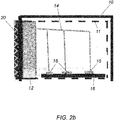
- each primary semi-exchanger 12 for the same number of pairs of fluid lines 13, 14 as the electronic elements 15 to be cooled in such a way that each electronic element 15 is cooled by a respective circuit formed by a liquid line 13 and a vapour line 14 which detach from the primary semi-exchanger 12 or which detach from a main liquid line 13 (liquid distribution) and a main vapour line 14 (vapour collection) as illustrated in Fig. 2b .
- the electronic components of a board are generally coupled to a heat sink formed by a thin plate in copper or aluminium (not illustrated in the drawings), even if other techniques of dissipation are likewise used: therefore the position and type of assembly of the fluid lines 13, 14 of a primary semi-exchanger 12 according to the invention will be determined according to the type of rack, and in any case always so as to have a thermal connection between the source of heat and the present cooling system.
- the liquid line 13 absorbs the dissipated heat by the electronic element 15, transforming into vapour which flows along the vapour line 14.
- Said vapour line 14 converges into the plenum chamber of said primary semi-exchanger 12, transforming again into liquid by means of condensation.
- Each semi-exchanger 12 intended for the relative drawer 11 also comprises a particular exchange surface or plate 20 ( Figs. 3a-3b ) which acts as heat sink element, being made in copper or another material with high thermal conductivity.
- Each primary semi-exchanger 12 is also attached on the back of the relevant drawer 11, by means of known magnetic or mechanical systems, such as for example screws and bolts 21, as illustrated in Figures 3a and 3b and in such a way that the exchange plate 20, which closes the plenum chamber, is outside of the relative drawer 11 so as to be able to transfer efficiently to the secondary semi-exchanger 120 all the heat which the primary semi-exchanger 12 has subtracted from the relative drawer 11.
- each primary semi-exchanger 12 is also attached to the secondary semi-exchanger 120 intended for the rack 10 by means of known mechanical or magnetic systems such as, for example, screws and bolts 22, so as to ensure the complete contact between the surfaces of the heat sink plate 20 of the primary semi-exchangers 12 and the heat sink plate 20 of the secondary semi-exchanger 120.
- cooling liquid is wholly contained in the closed circuit formed by said lines of fluid 13, 14 integral with the semi-exchanger 12 in turn integral with the back of the structure of the rack it is possible to extract easily each drawer 11 without losses of cooling liquid.
- each drawer 11 is absolutely independent from the others and from the rest of the general plant for dissipation of the heat towards the outside ( Fig. 6 ).
- the heat exchange plate 20 of the primary exchangers 12 and that of the secondary semi-exchanger 120 can have a flat surface or, preferably, a surface with shaped profile to increase the surface of heat exchange through conduction.
- said exchange surface of said plate 20 of said primary exchangers 12 and secondary exchangers 120 is shaped like saw teeth, with projecting prismatic elements, as illustrated in Figs. 5a-d , even if this embodiment is not binding for the purpose of the present invention.
- the secondary semi-exchanger 120 is also preferably a heat exchange unit functioning as a heat pipe, even if this is not binding for the purpose of the present invention.
- said secondary semi-exchanger 120 can be, in alternative to the heat pipe, a normal circuit with circulation of water or water/glycol, without a change of physical state. In this latter case the use of a circulation pump also has to be provided. Said secondary semi-exchanger 120 is also provided with an exchange plate 20 with an exchange surface shaped in a similar and complementary manner to that of the heat sink plate 20 of the primary semi-exchanger 12 with which it has to couple frontally.
- said secondary semi-exchanger 120 is appropriately dimensioned, according to the number of primary semi- exchangers 12 with which it has to be associated.
- the plates 20 of the secondary semi-exchanger 120 and of the primary semi-exchanger 12 have in any case to be coplanar and can also be covered with conductive paste.
- the primary semi-exchanger 12 attached to the drawer 11 is dimensioned in such a way as to feed, via the liquid line 13, a cooling liquid having a temperature around 50°C to an electronic circuit 15, and such as to remove the quantity of heat dissipated necessary for maintaining said electronic circuit 15 at a working temperature of 60°C or lower.
- the heat generated by the electronic circuit 15 makes the liquid circulating in the line 13 evaporate and the vapour generated, having a temperature of approximately 60°C, returns towards the cold area of the primary semi-exchanger 12 via the vapour piping 14, condensing in the plenum chamber 5.
- pressure inlets 60 and/or indicators of liquid/level 61 and/or a sensor 62 of temperature of the exchange plate 20 can be provided, in order to manage in a more efficient manner the exchange temperatures of each primary semi-exchanger 12, in particular in order to transmit one or more signals to a control system 63, such as for example CPU, PLC, data logger or the like.
- the heat deriving from the condensation of the vapour circulating in the vapour line 14 is transferred to the heat sink plate 20 of said primary semi-exchanger 12, which is in contact with the heat exchange plate 20 of the secondary semi-exchanger 120.
- the secondary semi-exchanger 120 is designed in such a way that the heat that it receives through the heat sink plate 20 of said primary semi-exchanger 12 makes the secondary cooling liquid evaporate at a temperature of approximately 50°C. This vapour is then condensed at a temperature of approximately 40°C which is that considered in the dimensioning as maximum outside temperature of the air.
- the increased surface temperature of the electronic components makes it in fact possible to apply the functioning of heat pipes to the system of the present invention in order to dispose of directly to the exterior, and without other mediations, the heat produced by the components, excluding refrigeration machines completely.
- a gradient varying from 20 to 30°C can be used, sufficient for efficiently activating a heat pipe with phase transformation.
- the semi-exchangers 12, 120 which, joined, make up the actual exchanger of the present cooling system, can be made in the most widely differing ways in order to obtain the maximum efficiency in the transmission of heat.
- each drawer 11 of the rack 10 to have its own primary semi-exchanger 12, dimensioned on the basis of the quantity of heat to be removed (and therefore on the basis of the number of electronic elements 15) and for the secondary semi-exchanger 120 to be dimensioned in order to remove the heat transmitted by all the primary semi-exchangers 12 intended for the drawers 11 of a rack 10: thanks to the fact that one or more secondary semi-exchangers 120 of rack 10 is connected to a dry cooler 100 placed outside the room 50 (or to another type of system of dissipation of the heat of condensation of the secondary fluid of the secondary semi-exchanger 120), it is possible to subtract from the server room 50 all the heat generated by the racks 10 present in the room.
- the abovementioned dry cooler 100 can be: a) a dry cooler, static or mechanically ventilated, also with optional adiabatic pre-cooling of the air by means of finely sprayed water.
- said secondary semi-exchanger 120 can be associated with another type of system of dissipation of the heat of condensation, different from the dry cooler 100, such as for example:
- a further object of the present invention is a dissipation plant comprising a cooling system as described above where each secondary semi-exchanger 120, associated with a respective rack 10, is connected to an external dry cooler 100 or to a similar machine via a series of pipings.
- the dissipation plant comprising a cooling system as described above provides for the fluid lines 13, 14 of each secondary semi-exchanger 120 to converge in respective fluid collectors 130, 140 which exit from the room 50, where said liquid collector and said vapour collector are connected to the dry cooler 100.
- the cooling system of the second embodiment and third embodiment of the present invention sets out to cool the electronic elements 15 of a rack 10 without using the aforementioned intermediate exchangers between the source of heat (electronic elements 15) and external heat sink, and without any mechanical member for the heat transport, using the entire difference of temperature available between the source and external environment so as to reduce further the energy input while achieving an efficient cooling.
- the cooling system of the second and third embodiments provides for the use of a single plant of heat dispersion which groups together several racks 10, without the mediation of exchangers which, by reducing the difference in temperature between the heating element (electronic element 15) and the outside, entail a smaller, albeit good, efficiency of the plant itself.
- the system is able to cool the electronic elements to a considerably lower temperature with respect to that which can be obtained with the system having the two semi-exchangers, even at the same temperature of the means disposing the heat (e.g. external air at 40°C) and at the same heat exchange surfaces.
- the pipes 13 and 14 forming a heat pipe housed inside a drawer are no longer connected to a semi-exchanger with thermally conductive plate but to two small collectors 23, 24, in turn connected to larger collectors 230, 240 which serve all the drawers 11 of a rack 10 ( Figs. 7a , 7b ) as will be illustrated here below in greater detail.
- Said heat pipes are preferably in copper, with a preferably flattened profile so as to increase the surface of heat exchange with the electronic element 15 ( Fig. 9c ).
- the slim flat heat pipes are similar to cylindrical heat pipes: they are composed of an empty receptacle, hermetically sealed, which contains a coolant fluid and of a closed capillary system of recirculation of the fluid.
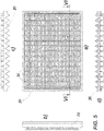
- Figure 9a shows a plurality of heat pipes parallel one to the other where each heat pipe is in contact with several electronic elements 15 aligned one with the other: it is in any case understood that different paths and/or arrangements of said heat pipes can be provided for without thereby departing from the scope of the present invention.
- each of said heat pipes are both open in that they converge, from one side, into a small vapour collector 24, while on the other side they converge into a small liquid collector 23, both said small collectors 23, 24 being placed inside the drawer 11 of the rack 10 ( Fig. 7a ).
- the vapour lines or sections 14 of the heat pipes converge ( Fig. 8 ), while the liquid lines or sections 13 of the heat pipes converge in the small liquid collector 23 ( Fig. 8 ).
- connection between the ends of the liquid lines 13 and the small liquid collector 23 takes place by means of a pipe union 40 which ensures the hermetic sealing of said lines entering the respective cold collector 23.
- connection between the ends of the vapour lines 14 and the small vapour collector 24 takes place by means of a pipe union 40 which ensures the hermetic sealing of said lines entering the respective hot collector 24.
- Said pipe union 40 is blocked on the nipples welded to the collectors so as to make each of said heat pipes closed hermetically at both ends.
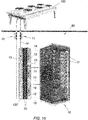
- each small liquid collector 23 placed inside each drawer 11 is then in turn connected to a larger liquid collector 230 ( Fig. 9a ) placed on the outer wall of the back of the rack 10, by means of a respective flexible small tube 231 which places in fluid (liquid) communication each small liquid collector 23 inside the drawer 11 with the larger external liquid collector 230 (hereinafter also referred to as larger cold collector for the sake of simplicity) associated with the rack 10.
- each small vapour collector 24 inside each drawer 11 is in turn connected to a larger vapour collector 240 placed externally on the back of the rack 10, using a respective flexible tube 241 which places in fluid (vapour) communication each small vapour collector 24 of the drawer 11 with the larger vapour collector 240 (hereinafter also referred to as larger hot collector for the sake of simplicity) of the rack 10.
- the two larger vapour 240 and liquid 230 collectors of the rack 10 are positioned vertically on the rear wall of the rack 10 and are mechanically integral with the metal structure of the same drawer 11 ( Fig. 10a ).
- the flexible pipes 231, 241 to be used in the present system can be for example the known flexible tubes used in the refrigeration systems.
- Each flexible tube 231, 241 of a drawer 11 is connected, at one of its ends, to the respective small liquid or vapour collector 23, 24 via a pipe union joint 33 ( Fig. 9a ).
- Said pipe union joint 33 is then locked on a nipple welded to the small collectors 24, 23 so as to make the circuit closed hermetically.
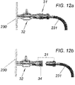
- each flexible tube 231, 241 a respective quick coupling joint 31 is provided ( Fig. 12a, 12b ) which engages in the respective manual tap 32 ( Fig. 9a ) which is mounted on the vapour 240 and liquid 230 collectors of the rack 10, so as to tightly connect the respective larger vapour 240 and liquid 230 collector of the rack 10 to the smaller vapour 24 and liquid 23 collectors of each drawer 11.
- the quick coupling hydraulic joint 31 for example of the AEROQUIP type, is made up of two half-joints ( Figs. 12a, 12b ): a male half-joint, provided with a ring nut, which is integral with the respective flexible tube 231, 241 exiting from the drawer 11, and a female half-joint which is integral with the respective manual tap 32 placed on the vapour 240 and liquid 230 collectors of the rack 10.
- the manual tap 32 can be considered as a cut-off element having a female side suitable for the male half-joints of the sealed quick connectors 31.
- the quick connectors 31 allow the disconnection or detachment of the drawer 11 without loss of fluid while the flexible tubes 231, 241 facilitate the manoeuvres of detachment/attachment without the need for precision positioning between the parts to be connected, so as to be able to extract easily from the rack the boards 15, involved in replacements or repairs, without having to put the general plant out of service.
- each drawer 11 of the rack 10 will be fitted with male half-joints of the same type, apt to engage in the female half-joints provided on the collectors 230, 240 of the rack 10 so as to form quick couplings 31.
- the ring nut of the joint 31 will be locked for greater security of mechanical sealing so as to ensure that all the small collectors 24, 23 of the drawers 11 remain integral with the two larger hot 240 and cold 240 collectors of the rack 10, thus realising a continuous circuit between the collectors 230, 240 and the heat pipes which cool the electronic components 15.
- vapour delivery line (or hot gas) 260 From each vapour collector 240 of each rack 10 a respective vapour delivery line (or hot gas) 260 departs which
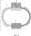
- the collectors 230, 240 of the various racks 10 contained in the server room 50 are connected, via appropriate pipings 260, 261, to two separate general pipings 130, 140 of greater size, to be proportioned on the basis of the thermal power to be dissipated.
- said collectors 230, 240 of the racks 10 are all parallel one to the other.
- Said pipings of greater size 130, 140, placed slanted as per Fig. 11 in order to facilitate the flow of the coolant and increase the efficiency of the system, will be taken outside the building of the server room 50, for example on the roof.
- said general central pipings 130, 140 will be connected one to the other and to the dry cooler ventilated (or to an adiabatic cooling tower) by means of normal joints or simply with welds.
- the coolant R134a was developed to replace the R12 in automotive air conditioning systems. It is available pure or as mixture. Moreover, R134a replaces R12 and R500 in refrigerators, both in average residential and commercial applications of refrigeration. R134a was assessed as A1 by the American company ASHRAE in the safety of heating, refrigeration and air conditioning plants. R134a also has a depletion potential equal to zero as regards the hole in the ozone layer, a global warming potential of 1430 and specific heat of 1.42 (kj)/(kg *k).
- Fig. 11 In practice the cooling system illustrated in Fig. 11 is a loop system inside the drawers 11 and loop for the general plant.
- the constructor of the electronic boards 15 and the assembler of the rack 10 must perform the circuiting of the internal cooling system according to the loop heat pipe system, distinguishing between pipes of the evaporated fluid and those of the condensed liquid.
- the entire plant made in this way behaves like a single loop heat pipe, without any interruption from the thermal viewpoint, using directly the entire difference of temperature between the external air and the electronic elements to be cooled, with the maximum yield possible.
- the system of the present second embodiment also works without the aid of circulation pumps and the only energy required is optionally that of the fans of the dry cooler 100 (or of another type of external heat sink as mentioned above), when and if required by the variations in external temperature.
- the system of the second embodiment of the present invention allows virtually annulment of maintenance which is reduced to the sole periodical check of the dry cooler 100 or of the adiabatic tower, elements which notoriously need for no frequent maintenance operations.
- the dry cooler 100 or the adiabatic tower, can be equipped with inverter control systems which will allow a reduction to the minimum of the energy used, maintaining the temperature of the coolant fluid constant.
- the plant formed in this way does not require any consumption of energy for the transport of the cooling fluid which takes place simply through temperature difference as in a heat pipe. It can be said that the only guiding force of the system is the actual heat to be dissipated.
- the only electrical devices in motion are represented by the fans of the dry cooler 100 or of the evaporation towers, placed outside the room or area 50.
- This cooling system of the second embodiment shows a hydraulic continuity between the heat pipes inside the racks and the general dissipation system, without thermal interruptions, creating a single "heat pipe", given that the first fluid and the second fluid are the same in this second embodiment.
- the unquestionable advantages of the system have already been extensively described and can be summed up as:
- the cooling system is substantially similar to that of the second embodiment with the exception of the fact that the heat pipes associated with the electronic elements 15 are pipes having only one of the two ends open - the end which disperses heat - while the other end is closed (the so-called simple or monopipe heat pipes).
- the open end of the heat pipe feeds into a single small collector 61 inside the drawer 11.
- this collector 61 there is the co-existence of vapour and liquid in that through the effect of the heat produced by the CPUs 15 the cooling liquid evaporates, accumulating in the upper part of the collector 61, drawing inside the tubes other liquid fluid which evaporates.
- the cycle continues, fed by the heat generated by the CPUs 15.
- each monopipe heat pipe is connected to the small vapour/liquid collector 61 by means of a pipe union 40 to be locked on a nipple welded to the collector 61.
- the heat pipes are preferably flat.
- intermediate exchangers are excluded, and the drawers can be extracted without loss of coolant, acting on the already provided tight quick connectors 31 and for the operations to be performed on the boards 15 of the drawer 11 the previous procedural indications apply.
Landscapes
- Engineering & Computer Science (AREA)
- Computer Hardware Design (AREA)
- General Engineering & Computer Science (AREA)
- Physics & Mathematics (AREA)
- Thermal Sciences (AREA)
- Microelectronics & Electronic Packaging (AREA)
- Cooling Or The Like Of Electrical Apparatus (AREA)
Priority Applications (1)
| Application Number | Priority Date | Filing Date | Title |
|---|---|---|---|
| PL17196858T PL3324716T3 (pl) | 2016-10-27 | 2017-10-17 | Układ chłodzący elementy elektroniczne wytwarzające ciepło |
Applications Claiming Priority (1)
| Application Number | Priority Date | Filing Date | Title |
|---|---|---|---|
| IT102016000108608A IT201600108608A1 (it) | 2016-10-27 | 2016-10-27 | Sistema di raffreddamento di componenti elettronici produttori di calore |
Publications (3)
| Publication Number | Publication Date |
|---|---|
| EP3324716A2 true EP3324716A2 (de) | 2018-05-23 |
| EP3324716A3 EP3324716A3 (de) | 2018-08-08 |
| EP3324716B1 EP3324716B1 (de) | 2022-01-19 |
Family
ID=58163010
Family Applications (1)
| Application Number | Title | Priority Date | Filing Date |
|---|---|---|---|
| EP17196858.9A Active EP3324716B1 (de) | 2016-10-27 | 2017-10-17 | System zur kühlung von wärmeerzeugenden elektronischen bauteilen |
Country Status (5)
| Country | Link |
|---|---|
| EP (1) | EP3324716B1 (de) |
| DK (1) | DK3324716T3 (de) |
| ES (1) | ES2910707T3 (de) |
| IT (1) | IT201600108608A1 (de) |
| PL (1) | PL3324716T3 (de) |
Cited By (11)
| Publication number | Priority date | Publication date | Assignee | Title |
|---|---|---|---|---|
| CN109874275A (zh) * | 2019-01-18 | 2019-06-11 | 广东合一新材料研究院有限公司 | 一种干湿分离式机箱及使用该机箱的网络设备 |
| CN110958814A (zh) * | 2019-12-09 | 2020-04-03 | 华南理工大学 | 一种服务器用柔性相变传热降温器 |
| CN112018635A (zh) * | 2020-07-09 | 2020-12-01 | 安徽金御科技发展有限公司 | 电器设备防潮装置 |
| IT201900023076A1 (it) * | 2019-12-05 | 2021-06-05 | Provides Metalmeccanica S R L | Sistema di raffreddamento per data center |
| WO2021111387A1 (en) * | 2019-12-05 | 2021-06-10 | Provides Metalmeccanica S.R.L. | Cooling system of electronic systems, in particular for data centre |
| CN114007372A (zh) * | 2020-07-28 | 2022-02-01 | 华为技术有限公司 | 一种散热机柜及通信设备 |
| FR3113221A1 (fr) * | 2020-07-30 | 2022-02-04 | Calyos Sa | Système pour refroidir des cartes serveurs dans un centre de données |
| CN115086520A (zh) * | 2022-06-07 | 2022-09-20 | 江西师范高等专科学校 | 一种思政远程教学用录像设备 |
| EP4181642A1 (de) * | 2021-11-16 | 2023-05-17 | JJ Cooling Innovation Sàrl | Kühlsystem für elektronikkomponentengestelle |
| CN116456679A (zh) * | 2023-04-19 | 2023-07-18 | 上海翠杉科技有限公司 | 一种web3-dcs户外便捷部署的服务器系统 |
| WO2023225092A1 (en) * | 2022-05-20 | 2023-11-23 | Seguente, Inc. | Manifold systems, devices, and methods for thermal management of hardware components |
Family Cites Families (11)
| Publication number | Priority date | Publication date | Assignee | Title |
|---|---|---|---|---|
| US7133283B2 (en) * | 2002-01-04 | 2006-11-07 | Intel Corporation | Frame-level thermal interface component for transfer of heat from an electronic component of a computer system |
| JP2010212533A (ja) * | 2009-03-12 | 2010-09-24 | Fujikura Ltd | 局部冷却装置 |
| TWI419641B (zh) * | 2010-10-29 | 2013-12-11 | Ind Tech Res Inst | 電子裝置之散熱結構 |
| US20150233619A1 (en) * | 2011-06-27 | 2015-08-20 | Ebullient, Llc | Method of providing stable pump operation in a two-phase cooling system |
| US9049803B2 (en) * | 2011-09-22 | 2015-06-02 | Panduit Corp. | Thermal management infrastructure for IT equipment in a cabinet |
| US10123464B2 (en) * | 2012-02-09 | 2018-11-06 | Hewlett Packard Enterprise Development Lp | Heat dissipating system |
| US9459031B2 (en) * | 2012-02-14 | 2016-10-04 | Nec Corporation | Cooling apparatus and cooling system |
| US9144179B2 (en) * | 2013-02-01 | 2015-09-22 | Dell Products, L.P. | System and method for powering multiple electronic devices operating within an immersion cooling vessel |
| JP6344385B2 (ja) * | 2013-05-28 | 2018-06-20 | 日本電気株式会社 | 冷却システム及び冷却方法 |
| JP2015012282A (ja) * | 2013-07-02 | 2015-01-19 | 富士通株式会社 | 電子装置 |
| US10231357B2 (en) * | 2015-03-20 | 2019-03-12 | International Business Machines Corporation | Two-phase cooling with ambient cooled condensor |
-
2016
- 2016-10-27 IT IT102016000108608A patent/IT201600108608A1/it unknown
-
2017
- 2017-10-17 EP EP17196858.9A patent/EP3324716B1/de active Active
- 2017-10-17 ES ES17196858T patent/ES2910707T3/es active Active
- 2017-10-17 DK DK17196858.9T patent/DK3324716T3/da active
- 2017-10-17 PL PL17196858T patent/PL3324716T3/pl unknown
Cited By (18)
| Publication number | Priority date | Publication date | Assignee | Title |
|---|---|---|---|---|
| CN109874275B (zh) * | 2019-01-18 | 2024-03-12 | 广东西江数据科技有限公司 | 一种干湿分离式机箱及使用该机箱的网络设备 |
| CN109874275A (zh) * | 2019-01-18 | 2019-06-11 | 广东合一新材料研究院有限公司 | 一种干湿分离式机箱及使用该机箱的网络设备 |
| IT201900023076A1 (it) * | 2019-12-05 | 2021-06-05 | Provides Metalmeccanica S R L | Sistema di raffreddamento per data center |
| WO2021111387A1 (en) * | 2019-12-05 | 2021-06-10 | Provides Metalmeccanica S.R.L. | Cooling system of electronic systems, in particular for data centre |
| US11871546B2 (en) | 2019-12-05 | 2024-01-09 | Wieland Provides SRL | Cooling system of electronic systems, in particular for data centre |
| CN110958814A (zh) * | 2019-12-09 | 2020-04-03 | 华南理工大学 | 一种服务器用柔性相变传热降温器 |
| CN110958814B (zh) * | 2019-12-09 | 2024-05-03 | 广州智冷节能科技有限公司 | 一种服务器用柔性相变传热降温器 |
| CN112018635A (zh) * | 2020-07-09 | 2020-12-01 | 安徽金御科技发展有限公司 | 电器设备防潮装置 |
| CN114007372A (zh) * | 2020-07-28 | 2022-02-01 | 华为技术有限公司 | 一种散热机柜及通信设备 |
| FR3113221A1 (fr) * | 2020-07-30 | 2022-02-04 | Calyos Sa | Système pour refroidir des cartes serveurs dans un centre de données |
| US11997832B2 (en) | 2020-07-30 | 2024-05-28 | Calyos Sa | System for cooling server boards in a data center |
| WO2023088865A3 (en) * | 2021-11-16 | 2023-06-29 | JJ Cooling Innovation Sàrl | Cooling system for electronic component racks |
| EP4181642A1 (de) * | 2021-11-16 | 2023-05-17 | JJ Cooling Innovation Sàrl | Kühlsystem für elektronikkomponentengestelle |
| WO2023225092A1 (en) * | 2022-05-20 | 2023-11-23 | Seguente, Inc. | Manifold systems, devices, and methods for thermal management of hardware components |
| US12324131B2 (en) | 2022-05-20 | 2025-06-03 | Seguente, Inc. | Manifold systems, devices, and methods for thermal management of hardware components |
| CN115086520B (zh) * | 2022-06-07 | 2023-04-18 | 江西师范高等专科学校 | 一种思政远程教学用录像设备 |
| CN115086520A (zh) * | 2022-06-07 | 2022-09-20 | 江西师范高等专科学校 | 一种思政远程教学用录像设备 |
| CN116456679A (zh) * | 2023-04-19 | 2023-07-18 | 上海翠杉科技有限公司 | 一种web3-dcs户外便捷部署的服务器系统 |
Also Published As
| Publication number | Publication date |
|---|---|
| EP3324716A3 (de) | 2018-08-08 |
| PL3324716T3 (pl) | 2022-05-16 |
| EP3324716B1 (de) | 2022-01-19 |
| ES2910707T3 (es) | 2022-05-13 |
| IT201600108608A1 (it) | 2018-04-27 |
| DK3324716T3 (da) | 2022-04-04 |
Similar Documents
| Publication | Publication Date | Title |
|---|---|---|
| EP3324716B1 (de) | System zur kühlung von wärmeerzeugenden elektronischen bauteilen | |
| KR101697882B1 (ko) | 스위치 캐비닛의 실내에 배치된 부품들을 위한 냉각 장치 | |
| US9363930B2 (en) | Passive two phase cooling solution for low, medium and high voltage drive systems | |
| CN106686953B (zh) | 一种机柜服务器用液冷热管散热系统及其控制方法 | |
| US10724748B2 (en) | Air-conditioning apparatus | |
| CN104813757B (zh) | 具有开关柜和冷却设备的冷却装置 | |
| AU682917B2 (en) | An air cooling system | |
| US11184996B1 (en) | Double sided heat exchanger cooling unit | |
| EP2677848B1 (de) | Wärmetauscher und kammer dafür | |
| JP6717080B2 (ja) | 情報処理装置、及び冷却ユニット | |
| CN106949653B (zh) | 应用于数据中心的冷却系统 | |
| JP2009529237A (ja) | サーバーベースデータセンタを冷却するためのシステム及び方法 | |
| KR20150031574A (ko) | 공기 조화기 | |
| WO2010042572A2 (en) | High-efficiency, fluid-cooled ups converter | |
| AU2003223877A1 (en) | Refrigeration power plant | |
| CN210015419U (zh) | 半导体器件散热装置及数据中心机房 | |
| WO2017124689A1 (zh) | 用于数据中心机柜的冷却装置、机柜和冷却系统 | |
| MXPA04000539A (es) | Sistema modular de calentamiento o refrigeracion. | |
| CN113692207A (zh) | 冷却装置和具有其的数据中心 | |
| CN204518299U (zh) | 智能控制柜温度调节装置 | |
| CN114245665A (zh) | 一种散热组件及空调 | |
| CN103490597A (zh) | 一种变流器的冷却系统 | |
| CN104932571B (zh) | 智能温度调节系统及其应用 | |
| CN113654112A (zh) | 一种多模式切换二级空调系统及运行方法 | |
| JP2022174869A (ja) | 多元冷凍サイクル装置 |
Legal Events
| Date | Code | Title | Description |
|---|---|---|---|
| PUAI | Public reference made under article 153(3) epc to a published international application that has entered the european phase |
Free format text: ORIGINAL CODE: 0009012 |
|
| STAA | Information on the status of an ep patent application or granted ep patent |
Free format text: STATUS: THE APPLICATION HAS BEEN PUBLISHED |
|
| AK | Designated contracting states |
Kind code of ref document: A2 Designated state(s): AL AT BE BG CH CY CZ DE DK EE ES FI FR GB GR HR HU IE IS IT LI LT LU LV MC MK MT NL NO PL PT RO RS SE SI SK SM TR |
|
| AX | Request for extension of the european patent |
Extension state: BA ME |
|
| PUAL | Search report despatched |
Free format text: ORIGINAL CODE: 0009013 |
|
| AK | Designated contracting states |
Kind code of ref document: A3 Designated state(s): AL AT BE BG CH CY CZ DE DK EE ES FI FR GB GR HR HU IE IS IT LI LT LU LV MC MK MT NL NO PL PT RO RS SE SI SK SM TR |
|
| AX | Request for extension of the european patent |
Extension state: BA ME |
|
| RIC1 | Information provided on ipc code assigned before grant |
Ipc: H05K 7/20 20060101AFI20180702BHEP |
|
| STAA | Information on the status of an ep patent application or granted ep patent |
Free format text: STATUS: REQUEST FOR EXAMINATION WAS MADE |
|
| 17P | Request for examination filed |
Effective date: 20190115 |
|
| RBV | Designated contracting states (corrected) |
Designated state(s): AL AT BE BG CH CY CZ DE DK EE ES FI FR GB GR HR HU IE IS IT LI LT LU LV MC MK MT NL NO PL PT RO RS SE SI SK SM TR |
|
| STAA | Information on the status of an ep patent application or granted ep patent |
Free format text: STATUS: EXAMINATION IS IN PROGRESS |
|
| 17Q | First examination report despatched |
Effective date: 20200406 |
|
| GRAP | Despatch of communication of intention to grant a patent |
Free format text: ORIGINAL CODE: EPIDOSNIGR1 |
|
| STAA | Information on the status of an ep patent application or granted ep patent |
Free format text: STATUS: GRANT OF PATENT IS INTENDED |
|
| INTG | Intention to grant announced |
Effective date: 20211025 |
|
| GRAS | Grant fee paid |
Free format text: ORIGINAL CODE: EPIDOSNIGR3 |
|
| GRAA | (expected) grant |
Free format text: ORIGINAL CODE: 0009210 |
|
| STAA | Information on the status of an ep patent application or granted ep patent |
Free format text: STATUS: THE PATENT HAS BEEN GRANTED |
|
| AK | Designated contracting states |
Kind code of ref document: B1 Designated state(s): AL AT BE BG CH CY CZ DE DK EE ES FI FR GB GR HR HU IE IS IT LI LT LU LV MC MK MT NL NO PL PT RO RS SE SI SK SM TR |
|
| REG | Reference to a national code |
Ref country code: GB Ref legal event code: FG4D |
|
| REG | Reference to a national code |
Ref country code: CH Ref legal event code: EP |
|
| REG | Reference to a national code |
Ref country code: DE Ref legal event code: R096 Ref document number: 602017052458 Country of ref document: DE |
|
| REG | Reference to a national code |
Ref country code: AT Ref legal event code: REF Ref document number: 1464536 Country of ref document: AT Kind code of ref document: T Effective date: 20220215 |
|
| REG | Reference to a national code |
Ref country code: IE Ref legal event code: FG4D |
|
| REG | Reference to a national code |
Ref country code: DK Ref legal event code: T3 Effective date: 20220330 |
|
| REG | Reference to a national code |
Ref country code: SE Ref legal event code: TRGR |
|
| REG | Reference to a national code |
Ref country code: LT Ref legal event code: MG9D |
|
| REG | Reference to a national code |
Ref country code: ES Ref legal event code: FG2A Ref document number: 2910707 Country of ref document: ES Kind code of ref document: T3 Effective date: 20220513 |
|
| REG | Reference to a national code |
Ref country code: NL Ref legal event code: MP Effective date: 20220119 |
|
| REG | Reference to a national code |
Ref country code: AT Ref legal event code: MK05 Ref document number: 1464536 Country of ref document: AT Kind code of ref document: T Effective date: 20220119 |
|
| PG25 | Lapsed in a contracting state [announced via postgrant information from national office to epo] |
Ref country code: NL Free format text: LAPSE BECAUSE OF FAILURE TO SUBMIT A TRANSLATION OF THE DESCRIPTION OR TO PAY THE FEE WITHIN THE PRESCRIBED TIME-LIMIT Effective date: 20220119 |
|
| PG25 | Lapsed in a contracting state [announced via postgrant information from national office to epo] |
Ref country code: RS Free format text: LAPSE BECAUSE OF FAILURE TO SUBMIT A TRANSLATION OF THE DESCRIPTION OR TO PAY THE FEE WITHIN THE PRESCRIBED TIME-LIMIT Effective date: 20220119 Ref country code: PT Free format text: LAPSE BECAUSE OF FAILURE TO SUBMIT A TRANSLATION OF THE DESCRIPTION OR TO PAY THE FEE WITHIN THE PRESCRIBED TIME-LIMIT Effective date: 20220519 Ref country code: NO Free format text: LAPSE BECAUSE OF FAILURE TO SUBMIT A TRANSLATION OF THE DESCRIPTION OR TO PAY THE FEE WITHIN THE PRESCRIBED TIME-LIMIT Effective date: 20220419 Ref country code: LT Free format text: LAPSE BECAUSE OF FAILURE TO SUBMIT A TRANSLATION OF THE DESCRIPTION OR TO PAY THE FEE WITHIN THE PRESCRIBED TIME-LIMIT Effective date: 20220119 Ref country code: HR Free format text: LAPSE BECAUSE OF FAILURE TO SUBMIT A TRANSLATION OF THE DESCRIPTION OR TO PAY THE FEE WITHIN THE PRESCRIBED TIME-LIMIT Effective date: 20220119 Ref country code: BG Free format text: LAPSE BECAUSE OF FAILURE TO SUBMIT A TRANSLATION OF THE DESCRIPTION OR TO PAY THE FEE WITHIN THE PRESCRIBED TIME-LIMIT Effective date: 20220419 |
|
| PG25 | Lapsed in a contracting state [announced via postgrant information from national office to epo] |
Ref country code: LV Free format text: LAPSE BECAUSE OF FAILURE TO SUBMIT A TRANSLATION OF THE DESCRIPTION OR TO PAY THE FEE WITHIN THE PRESCRIBED TIME-LIMIT Effective date: 20220119 Ref country code: GR Free format text: LAPSE BECAUSE OF FAILURE TO SUBMIT A TRANSLATION OF THE DESCRIPTION OR TO PAY THE FEE WITHIN THE PRESCRIBED TIME-LIMIT Effective date: 20220420 Ref country code: FI Free format text: LAPSE BECAUSE OF FAILURE TO SUBMIT A TRANSLATION OF THE DESCRIPTION OR TO PAY THE FEE WITHIN THE PRESCRIBED TIME-LIMIT Effective date: 20220119 Ref country code: AT Free format text: LAPSE BECAUSE OF FAILURE TO SUBMIT A TRANSLATION OF THE DESCRIPTION OR TO PAY THE FEE WITHIN THE PRESCRIBED TIME-LIMIT Effective date: 20220119 |
|
| PG25 | Lapsed in a contracting state [announced via postgrant information from national office to epo] |
Ref country code: IS Free format text: LAPSE BECAUSE OF FAILURE TO SUBMIT A TRANSLATION OF THE DESCRIPTION OR TO PAY THE FEE WITHIN THE PRESCRIBED TIME-LIMIT Effective date: 20220519 |
|
| REG | Reference to a national code |
Ref country code: DE Ref legal event code: R097 Ref document number: 602017052458 Country of ref document: DE |
|
| PG25 | Lapsed in a contracting state [announced via postgrant information from national office to epo] |
Ref country code: SM Free format text: LAPSE BECAUSE OF FAILURE TO SUBMIT A TRANSLATION OF THE DESCRIPTION OR TO PAY THE FEE WITHIN THE PRESCRIBED TIME-LIMIT Effective date: 20220119 Ref country code: SK Free format text: LAPSE BECAUSE OF FAILURE TO SUBMIT A TRANSLATION OF THE DESCRIPTION OR TO PAY THE FEE WITHIN THE PRESCRIBED TIME-LIMIT Effective date: 20220119 Ref country code: RO Free format text: LAPSE BECAUSE OF FAILURE TO SUBMIT A TRANSLATION OF THE DESCRIPTION OR TO PAY THE FEE WITHIN THE PRESCRIBED TIME-LIMIT Effective date: 20220119 Ref country code: EE Free format text: LAPSE BECAUSE OF FAILURE TO SUBMIT A TRANSLATION OF THE DESCRIPTION OR TO PAY THE FEE WITHIN THE PRESCRIBED TIME-LIMIT Effective date: 20220119 Ref country code: CZ Free format text: LAPSE BECAUSE OF FAILURE TO SUBMIT A TRANSLATION OF THE DESCRIPTION OR TO PAY THE FEE WITHIN THE PRESCRIBED TIME-LIMIT Effective date: 20220119 |
|
| PLBE | No opposition filed within time limit |
Free format text: ORIGINAL CODE: 0009261 |
|
| STAA | Information on the status of an ep patent application or granted ep patent |
Free format text: STATUS: NO OPPOSITION FILED WITHIN TIME LIMIT |
|
| PG25 | Lapsed in a contracting state [announced via postgrant information from national office to epo] |
Ref country code: AL Free format text: LAPSE BECAUSE OF FAILURE TO SUBMIT A TRANSLATION OF THE DESCRIPTION OR TO PAY THE FEE WITHIN THE PRESCRIBED TIME-LIMIT Effective date: 20220119 |
|
| 26N | No opposition filed |
Effective date: 20221020 |
|
| PG25 | Lapsed in a contracting state [announced via postgrant information from national office to epo] |
Ref country code: SI Free format text: LAPSE BECAUSE OF FAILURE TO SUBMIT A TRANSLATION OF THE DESCRIPTION OR TO PAY THE FEE WITHIN THE PRESCRIBED TIME-LIMIT Effective date: 20220119 |
|
| PG25 | Lapsed in a contracting state [announced via postgrant information from national office to epo] |
Ref country code: MC Free format text: LAPSE BECAUSE OF FAILURE TO SUBMIT A TRANSLATION OF THE DESCRIPTION OR TO PAY THE FEE WITHIN THE PRESCRIBED TIME-LIMIT Effective date: 20220119 |
|
| REG | Reference to a national code |
Ref country code: CH Ref legal event code: PL |
|
| REG | Reference to a national code |
Ref country code: BE Ref legal event code: MM Effective date: 20221031 |
|
| PG25 | Lapsed in a contracting state [announced via postgrant information from national office to epo] |
Ref country code: LU Free format text: LAPSE BECAUSE OF NON-PAYMENT OF DUE FEES Effective date: 20221017 |
|
| PG25 | Lapsed in a contracting state [announced via postgrant information from national office to epo] |
Ref country code: LI Free format text: LAPSE BECAUSE OF NON-PAYMENT OF DUE FEES Effective date: 20221031 Ref country code: CH Free format text: LAPSE BECAUSE OF NON-PAYMENT OF DUE FEES Effective date: 20221031 |
|
| P01 | Opt-out of the competence of the unified patent court (upc) registered |
Effective date: 20230707 |
|
| PG25 | Lapsed in a contracting state [announced via postgrant information from national office to epo] |
Ref country code: BE Free format text: LAPSE BECAUSE OF NON-PAYMENT OF DUE FEES Effective date: 20221031 |
|
| PG25 | Lapsed in a contracting state [announced via postgrant information from national office to epo] |
Ref country code: IE Free format text: LAPSE BECAUSE OF NON-PAYMENT OF DUE FEES Effective date: 20221017 |
|
| PG25 | Lapsed in a contracting state [announced via postgrant information from national office to epo] |
Ref country code: HU Free format text: LAPSE BECAUSE OF FAILURE TO SUBMIT A TRANSLATION OF THE DESCRIPTION OR TO PAY THE FEE WITHIN THE PRESCRIBED TIME-LIMIT; INVALID AB INITIO Effective date: 20171017 |
|
| PG25 | Lapsed in a contracting state [announced via postgrant information from national office to epo] |
Ref country code: CY Free format text: LAPSE BECAUSE OF FAILURE TO SUBMIT A TRANSLATION OF THE DESCRIPTION OR TO PAY THE FEE WITHIN THE PRESCRIBED TIME-LIMIT Effective date: 20220119 |
|
| PG25 | Lapsed in a contracting state [announced via postgrant information from national office to epo] |
Ref country code: MK Free format text: LAPSE BECAUSE OF FAILURE TO SUBMIT A TRANSLATION OF THE DESCRIPTION OR TO PAY THE FEE WITHIN THE PRESCRIBED TIME-LIMIT Effective date: 20220119 |
|
| PG25 | Lapsed in a contracting state [announced via postgrant information from national office to epo] |
Ref country code: MT Free format text: LAPSE BECAUSE OF FAILURE TO SUBMIT A TRANSLATION OF THE DESCRIPTION OR TO PAY THE FEE WITHIN THE PRESCRIBED TIME-LIMIT Effective date: 20220119 |
|
| PGFP | Annual fee paid to national office [announced via postgrant information from national office to epo] |
Ref country code: DE Payment date: 20251029 Year of fee payment: 9 |
|
| PGFP | Annual fee paid to national office [announced via postgrant information from national office to epo] |
Ref country code: GB Payment date: 20251013 Year of fee payment: 9 |
|
| PGFP | Annual fee paid to national office [announced via postgrant information from national office to epo] |
Ref country code: DK Payment date: 20251027 Year of fee payment: 9 Ref country code: IT Payment date: 20251009 Year of fee payment: 9 |
|
| PGFP | Annual fee paid to national office [announced via postgrant information from national office to epo] |
Ref country code: FR Payment date: 20251022 Year of fee payment: 9 |
|
| PGFP | Annual fee paid to national office [announced via postgrant information from national office to epo] |
Ref country code: TR Payment date: 20251013 Year of fee payment: 9 |
|
| PGFP | Annual fee paid to national office [announced via postgrant information from national office to epo] |
Ref country code: SE Payment date: 20251021 Year of fee payment: 9 |
|
| PGFP | Annual fee paid to national office [announced via postgrant information from national office to epo] |
Ref country code: PL Payment date: 20251010 Year of fee payment: 9 |
|
| PGFP | Annual fee paid to national office [announced via postgrant information from national office to epo] |
Ref country code: ES Payment date: 20251216 Year of fee payment: 9 |