EP3325281B1 - Dispositif de sécurité et son procédé de fabrication - Google Patents
Dispositif de sécurité et son procédé de fabrication Download PDFInfo
- Publication number
- EP3325281B1 EP3325281B1 EP16744481.9A EP16744481A EP3325281B1 EP 3325281 B1 EP3325281 B1 EP 3325281B1 EP 16744481 A EP16744481 A EP 16744481A EP 3325281 B1 EP3325281 B1 EP 3325281B1
- Authority
- EP
- European Patent Office
- Prior art keywords
- diffractive
- diffractive structure
- regions
- diffraction
- diffraction pattern
- Prior art date
- Legal status (The legal status is an assumption and is not a legal conclusion. Google has not performed a legal analysis and makes no representation as to the accuracy of the status listed.)
- Active
Links
Images


Classifications
-
- B—PERFORMING OPERATIONS; TRANSPORTING
- B42—BOOKBINDING; ALBUMS; FILES; SPECIAL PRINTED MATTER
- B42D—BOOKS; BOOK COVERS; LOOSE LEAVES; PRINTED MATTER CHARACTERISED BY IDENTIFICATION OR SECURITY FEATURES; PRINTED MATTER OF SPECIAL FORMAT OR STYLE NOT OTHERWISE PROVIDED FOR; DEVICES FOR USE THEREWITH AND NOT OTHERWISE PROVIDED FOR; MOVABLE-STRIP WRITING OR READING APPARATUS
- B42D25/00—Information-bearing cards or sheet-like structures characterised by identification or security features; Manufacture thereof
- B42D25/20—Information-bearing cards or sheet-like structures characterised by identification or security features; Manufacture thereof characterised by a particular use or purpose
- B42D25/21—Information-bearing cards or sheet-like structures characterised by identification or security features; Manufacture thereof characterised by a particular use or purpose for multiple purposes
-
- B—PERFORMING OPERATIONS; TRANSPORTING
- B42—BOOKBINDING; ALBUMS; FILES; SPECIAL PRINTED MATTER
- B42D—BOOKS; BOOK COVERS; LOOSE LEAVES; PRINTED MATTER CHARACTERISED BY IDENTIFICATION OR SECURITY FEATURES; PRINTED MATTER OF SPECIAL FORMAT OR STYLE NOT OTHERWISE PROVIDED FOR; DEVICES FOR USE THEREWITH AND NOT OTHERWISE PROVIDED FOR; MOVABLE-STRIP WRITING OR READING APPARATUS
- B42D25/00—Information-bearing cards or sheet-like structures characterised by identification or security features; Manufacture thereof
- B42D25/20—Information-bearing cards or sheet-like structures characterised by identification or security features; Manufacture thereof characterised by a particular use or purpose
- B42D25/29—Securities; Bank notes
-
- B—PERFORMING OPERATIONS; TRANSPORTING
- B42—BOOKBINDING; ALBUMS; FILES; SPECIAL PRINTED MATTER
- B42D—BOOKS; BOOK COVERS; LOOSE LEAVES; PRINTED MATTER CHARACTERISED BY IDENTIFICATION OR SECURITY FEATURES; PRINTED MATTER OF SPECIAL FORMAT OR STYLE NOT OTHERWISE PROVIDED FOR; DEVICES FOR USE THEREWITH AND NOT OTHERWISE PROVIDED FOR; MOVABLE-STRIP WRITING OR READING APPARATUS
- B42D25/00—Information-bearing cards or sheet-like structures characterised by identification or security features; Manufacture thereof
- B42D25/30—Identification or security features, e.g. for preventing forgery
- B42D25/324—Reliefs
-
- B—PERFORMING OPERATIONS; TRANSPORTING
- B42—BOOKBINDING; ALBUMS; FILES; SPECIAL PRINTED MATTER
- B42D—BOOKS; BOOK COVERS; LOOSE LEAVES; PRINTED MATTER CHARACTERISED BY IDENTIFICATION OR SECURITY FEATURES; PRINTED MATTER OF SPECIAL FORMAT OR STYLE NOT OTHERWISE PROVIDED FOR; DEVICES FOR USE THEREWITH AND NOT OTHERWISE PROVIDED FOR; MOVABLE-STRIP WRITING OR READING APPARATUS
- B42D25/00—Information-bearing cards or sheet-like structures characterised by identification or security features; Manufacture thereof
- B42D25/30—Identification or security features, e.g. for preventing forgery
- B42D25/328—Diffraction gratings; Holograms
-
- B—PERFORMING OPERATIONS; TRANSPORTING
- B42—BOOKBINDING; ALBUMS; FILES; SPECIAL PRINTED MATTER
- B42D—BOOKS; BOOK COVERS; LOOSE LEAVES; PRINTED MATTER CHARACTERISED BY IDENTIFICATION OR SECURITY FEATURES; PRINTED MATTER OF SPECIAL FORMAT OR STYLE NOT OTHERWISE PROVIDED FOR; DEVICES FOR USE THEREWITH AND NOT OTHERWISE PROVIDED FOR; MOVABLE-STRIP WRITING OR READING APPARATUS
- B42D25/00—Information-bearing cards or sheet-like structures characterised by identification or security features; Manufacture thereof
- B42D25/30—Identification or security features, e.g. for preventing forgery
- B42D25/342—Moiré effects
-
- B—PERFORMING OPERATIONS; TRANSPORTING
- B42—BOOKBINDING; ALBUMS; FILES; SPECIAL PRINTED MATTER
- B42D—BOOKS; BOOK COVERS; LOOSE LEAVES; PRINTED MATTER CHARACTERISED BY IDENTIFICATION OR SECURITY FEATURES; PRINTED MATTER OF SPECIAL FORMAT OR STYLE NOT OTHERWISE PROVIDED FOR; DEVICES FOR USE THEREWITH AND NOT OTHERWISE PROVIDED FOR; MOVABLE-STRIP WRITING OR READING APPARATUS
- B42D25/00—Information-bearing cards or sheet-like structures characterised by identification or security features; Manufacture thereof
- B42D25/30—Identification or security features, e.g. for preventing forgery
- B42D25/36—Identification or security features, e.g. for preventing forgery comprising special materials
- B42D25/373—Metallic materials
-
- B—PERFORMING OPERATIONS; TRANSPORTING
- B42—BOOKBINDING; ALBUMS; FILES; SPECIAL PRINTED MATTER
- B42D—BOOKS; BOOK COVERS; LOOSE LEAVES; PRINTED MATTER CHARACTERISED BY IDENTIFICATION OR SECURITY FEATURES; PRINTED MATTER OF SPECIAL FORMAT OR STYLE NOT OTHERWISE PROVIDED FOR; DEVICES FOR USE THEREWITH AND NOT OTHERWISE PROVIDED FOR; MOVABLE-STRIP WRITING OR READING APPARATUS
- B42D25/00—Information-bearing cards or sheet-like structures characterised by identification or security features; Manufacture thereof
- B42D25/40—Manufacture
- B42D25/405—Marking
- B42D25/425—Marking by deformation, e.g. embossing
-
- B—PERFORMING OPERATIONS; TRANSPORTING
- B42—BOOKBINDING; ALBUMS; FILES; SPECIAL PRINTED MATTER
- B42D—BOOKS; BOOK COVERS; LOOSE LEAVES; PRINTED MATTER CHARACTERISED BY IDENTIFICATION OR SECURITY FEATURES; PRINTED MATTER OF SPECIAL FORMAT OR STYLE NOT OTHERWISE PROVIDED FOR; DEVICES FOR USE THEREWITH AND NOT OTHERWISE PROVIDED FOR; MOVABLE-STRIP WRITING OR READING APPARATUS
- B42D25/00—Information-bearing cards or sheet-like structures characterised by identification or security features; Manufacture thereof
- B42D25/40—Manufacture
- B42D25/405—Marking
- B42D25/43—Marking by removal of material
- B42D25/435—Marking by removal of material using electromagnetic radiation, e.g. laser
-
- G—PHYSICS
- G02—OPTICS
- G02B—OPTICAL ELEMENTS, SYSTEMS OR APPARATUS
- G02B5/00—Optical elements other than lenses
- G02B5/18—Diffraction gratings
- G02B5/1876—Diffractive Fresnel lenses; Zone plates; Kinoforms
-
- G—PHYSICS
- G07—CHECKING-DEVICES
- G07D—HANDLING OF COINS OR VALUABLE PAPERS, e.g. TESTING, SORTING BY DENOMINATIONS, COUNTING, DISPENSING, CHANGING OR DEPOSITING
- G07D7/00—Testing specially adapted to determine the identity or genuineness of valuable papers or for segregating those which are unacceptable, e.g. banknotes that are alien to a currency
- G07D7/003—Testing specially adapted to determine the identity or genuineness of valuable papers or for segregating those which are unacceptable, e.g. banknotes that are alien to a currency using security elements
- G07D7/0032—Testing specially adapted to determine the identity or genuineness of valuable papers or for segregating those which are unacceptable, e.g. banknotes that are alien to a currency using security elements using holograms
-
- B—PERFORMING OPERATIONS; TRANSPORTING
- B42—BOOKBINDING; ALBUMS; FILES; SPECIAL PRINTED MATTER
- B42D—BOOKS; BOOK COVERS; LOOSE LEAVES; PRINTED MATTER CHARACTERISED BY IDENTIFICATION OR SECURITY FEATURES; PRINTED MATTER OF SPECIAL FORMAT OR STYLE NOT OTHERWISE PROVIDED FOR; DEVICES FOR USE THEREWITH AND NOT OTHERWISE PROVIDED FOR; MOVABLE-STRIP WRITING OR READING APPARATUS
- B42D25/00—Information-bearing cards or sheet-like structures characterised by identification or security features; Manufacture thereof
- B42D25/20—Information-bearing cards or sheet-like structures characterised by identification or security features; Manufacture thereof characterised by a particular use or purpose
- B42D25/23—Identity cards
-
- B—PERFORMING OPERATIONS; TRANSPORTING
- B42—BOOKBINDING; ALBUMS; FILES; SPECIAL PRINTED MATTER
- B42D—BOOKS; BOOK COVERS; LOOSE LEAVES; PRINTED MATTER CHARACTERISED BY IDENTIFICATION OR SECURITY FEATURES; PRINTED MATTER OF SPECIAL FORMAT OR STYLE NOT OTHERWISE PROVIDED FOR; DEVICES FOR USE THEREWITH AND NOT OTHERWISE PROVIDED FOR; MOVABLE-STRIP WRITING OR READING APPARATUS
- B42D25/00—Information-bearing cards or sheet-like structures characterised by identification or security features; Manufacture thereof
- B42D25/20—Information-bearing cards or sheet-like structures characterised by identification or security features; Manufacture thereof characterised by a particular use or purpose
- B42D25/24—Passports
-
- B—PERFORMING OPERATIONS; TRANSPORTING
- B42—BOOKBINDING; ALBUMS; FILES; SPECIAL PRINTED MATTER
- B42D—BOOKS; BOOK COVERS; LOOSE LEAVES; PRINTED MATTER CHARACTERISED BY IDENTIFICATION OR SECURITY FEATURES; PRINTED MATTER OF SPECIAL FORMAT OR STYLE NOT OTHERWISE PROVIDED FOR; DEVICES FOR USE THEREWITH AND NOT OTHERWISE PROVIDED FOR; MOVABLE-STRIP WRITING OR READING APPARATUS
- B42D25/00—Information-bearing cards or sheet-like structures characterised by identification or security features; Manufacture thereof
- B42D25/30—Identification or security features, e.g. for preventing forgery
- B42D25/36—Identification or security features, e.g. for preventing forgery comprising special materials
- B42D25/378—Special inks
Definitions
- This invention relates to security devices for use in checking the authenticity of articles of value, particularly security documents such as banknotes, passports, identity documents, driving licences, stamps, visas and the like. Methods of making the security devices are also disclosed.
- Articles of value, and particularly documents of value are frequently the target of counterfeiters and persons wishing to make fraudulent copies thereof and/or changes to any data contained therein.
- objects are provided with a number of visible security devices for checking the authenticity of the object.
- visible security devices include features based on one or more patterns such as microtext, fine line patterns, latent images, venetian blind devices, lenticular devices, moire interference devices and moire magnification devices, each of which generates a secure visual effect.
- Other known security devices include holograms, watermarks, embossings, perforations and the use of colour-shifting or luminescent / fluorescent inks. Common to all such devices is that the visual effect exhibited by the device is extremely difficult, or impossible, to copy using available reproduction techniques such as photocopying.
- Security devices exhibiting non-visible effects such as magnetic materials may also be employed.
- One class of security devices are those which produce an optically variable effect, meaning that the appearance of the device is different at different angles of view. Such devices are particularly effective since direct copies (e.g. photocopies) will not produce the optically variable effect and hence can be readily distinguished from genuine devices.
- Optically variable effects can be generated based on various different mechanisms, including holograms and other diffractive devices such as KinegramsTM, and also devices which make use of focusing elements such as lenses, including moire magnifier devices, integral imaging devices and so-called lenticular devices.
- Diffractive security devices such as holograms and KinegramsTM have a number of benefits including the ability to generate strong and distinctive visual effects whilst being very difficult to replicate without specialist equipment. Nonetheless, new security devices and effects are necessary in order to stay ahead of counterfeiters' ability to imitate existing designs.
- Patent document WO 2010/121293 A1 discloses a diffractive security device comprising first and second diffractive structures defined in a carrier layer.
- a diffractive security device comprising first and second diffractive structures defined in a carrier layer,
- the security device By combining a diffractive zone plate structure with an off-axis diffractive structure in the above-described manner, the security device exhibits a new and particularly distinctive visual effect.
- the first and second diffraction patterns each exhibit a change upon altering the viewing angle (e.g. by tilting or rotating the device, defined below) which in itself results in a dynamic appearance which could not be copied by standard reproduction methods.
- the stationary reference point or line of the first diffraction pattern acts to emphasise the change exhibited by the second diffraction pattern upon tilting or rotation and also demonstrates register between the two effects, resulting in strong visual integration between the two. This leads to a memorable and easily describable feature which is extremely difficult to imitate.
- the reference point or line of the first diffraction pattern (or part of it) could fall within one of the second regions and therefore may not be visible (at least at some viewing angles). Nonetheless, its position will still be apparent by virtue of the features of the first diffraction pattern which move around it upon tilting or rotation.
- zone plate structure refers to a Fresnel-type arrangement of alternating bands of either high and low optical density (in a device operating on the principle of amplitude-difference) or high and low surface relief (in a device operating on the principle of phase-difference).
- Fresnel structures with a high reflection efficiency which typically give the appearance of a three-dimensional surface such as a mirror or lens
- diffractive zone plate structures as used in the presently disclosed device have a low reflection efficiency (achieved inter-alia by appropriate sizing of the structure, e.g.
- band-to-band spacings comparable to the wavelength of visible light, that is preferably less than 10 microns and more preferably less than 5 microns) and hence do not reconstruct an image of a 3D surface when viewed. Rather, different wavelengths are diffracted to different positions, resulting in a diffraction pattern which appears as a two-dimensional multi-coloured pattern, e.g. of spots of different colours, or "spread out" colours (when viewed under multi-chromatic illumination such as white light).
- zone plate structures are examples of "on-axis" diffraction structures and the first diffraction pattern will be visible at nearly all viewing angles (excluding highly oblique angles at which the device may act as a planar reflecting surface as will be the case for most diffracting structures).
- the first diffraction pattern is preferably visible at tilt angles ( ⁇ ) from zero to at least 30 degrees in all azimuthal directions, more preferably from zero to at least 60 degrees, and most preferably from zero to at least 85 degrees.
- the diffractive zone plate structure itself is still generated based on a 3D surface and the nature of that surface will dictate the lateral shape of the bands (i.e. their shape in plan view, viewed along the normal to the device).
- a zone structure of a hemi-sphere or another circular-based dome will comprise a series of concentric, circular bands centred on a point corresponding to the centre of the hemi-sphere.
- a fixed reference point corresponding to the same centre position will be visible, other features of the diffraction pattern appearing to move relative to that reference point when the viewing angle is changed.
- a zone structure of a semi-cylinder will comprises a series of straight, parallel bands on each side of a straight line corresponding to the long central axis of the cylinder. This will result in an invariant reference line in the same position in the diffraction pattern, on each side of which the multi-coloured pattern will be visible and appear to move.
- the continuously curved surface on which the zone plate structure is based could be an ellipsoid, in which case the bands would be concentric ovals and there may be two reference points (at the two focus points of the ellipse), or a toroid, in which case the reference line will be curved (e.g. a circle).
- any continuously curved surface can be utilised, the only requirement being that the gradient of its surface changes continuously (i.e. there are no flat/planar portions of the surface - or if such portions exist they are not represented in the zone plate structure, e.g. they fall outside the bounds of the first diffraction structure and, preferably, of the whole device).
- the diffractive structure is generated holographically, the curved surface in question will be used directly to produce the light interference pattern which is recorded and developed resulting in the first diffractive structure.
- the curved surface may be used in a mathematical model to determine the light interference pattern that would result from it and then the corresponding structure can be formed based on the output of the model, e.g. using an optical fringe writer or electron beam lithography.
- the diffractive replay from each portion of the second diffractive structure will only be visible across a respective subset of viewing angles, which subset is preferably different for each of the different portions (although the subsets may optionally partially overlap one another). This has the result that, at any one viewing angle, the appearance of the second diffraction pattern is different in each of the different portions - for instance, various portions may exhibit different colours from one another and/or appear "on" (i.e. diffract light to the viewer) or "off' (i.e. diffract no light to the viewer). As the viewing angle is changed, e.g. by tilting and/or rotation of the device, the appearance of each portion changes, e.g.
- the second diffraction pattern may appear to undergo a progressive change in colour, moving across the portions relative to the reference point or line, and/or the second diffraction pattern may appear to change in terms of shape, size and/or position relative to the reference point or line, by virtue of its different portions turning "on” and "off".
- both of the first and second diffraction patterns are exhibited across the device as a whole, i.e. both appearing to occupy the same overall area rather than being positioned side-by-side. That is, the second diffraction pattern will appear laterally inside the periphery of the first (at least partially) and vice versa.
- the two effects appear superimposed on one another, at least on a large scale.
- the second regions collectively cover 50% or less of the total area of the security device.
- the second diffractive structure will be present in each second region (i.e. the first diffractive structure will be absent in the second regions).
- each second region should be large enough to be individually distinguished by the naked eye, this has the result that the second regions will not exhibit the first diffractive effect at any viewing angles. Therefore, at viewing angles at which the second diffractive effect is not visible from the second region in question (i.e. it appears "off'), the second region appears as a gap or artefact interrupting the first diffraction pattern which will be exhibited by the first regions on either side (since the first diffraction pattern is visible at all viewing angles). This is undesirable and so in more preferred embodiments, both the first and second diffractive structures will be present and combined with one another in each second region, to thereby reduce this effect. Various manners in which this can be achieved will be discussed further below.
- the diffractive zone plate structure preferably defines a series of alternating maxima and minima lines (i.e. the "bands" referred to above) which in the case of an amplitude difference zone plate structure correspond to locations of relatively high and relatively low opacity of the carrier layer, respectively, and in the case of a phase difference zone plate structure correspond to locations of peaks and troughs, respectively, in a surface relief of the carrier layer, the distance of the n th maxima line from the reference point along any one direction or from the reference line along the orthogonal direction being approximately proportional to the square root of n.
- the proportionality constant may be the same in all directions (as would be the case in a circular zone plate structure), or could vary (e.g. in an elliptical zone plate structure).
- ⁇ is selected according to which wavelength(s) of illumination the pattern is to be viewed under. Hence the value of ⁇ should fall within the visible light spectrum, e.g. between about 390 to 700nm. In preferred examples a value of around 550nm is selected since this represents an approximate average of visible light wavelengths. Again in a circular-based device the same expression above will apply in all directions emanating from the reference point (i.e.
- r radius
- ⁇ and f radius
- the preferred value of f (which represents the focal length of the structure, if it were acting as a lens or mirror) is a matter of choice to the skilled man.
- the focal length f represents the forward and reverse "depth" of the device. If the focal length f is much greater than half the lateral dimension of the optically active region of the security device then the forward and reverse focal spots (the bright regions discussed below) will swing outside the dimensions of the device as the viewing position moves away from the device normal. Conversely if the focal length is much less than half the lateral dimension of the optically active region of the security device then the sense of forward and reverse depth will be diminished.
- the focal length f is similar in value to or less than half the lateral dimension of the optically active region of the security device.
- suitable ranges for the focal length f would be between 10mm and 30mm.
- the choice of 10mm will result in focal spots (bright regions) which remain within the dimensions of the device at even the most oblique viewing angles (greater than 75 degrees) but with a perceived forward and reverse depth noticeably less than the dimensions of the device, whereas 30mm will give twice the perceived forward and reverse depth but the focal spots will swing or move out of view for viewing angles greater than 45 degrees.
- the focal length f will vary with wavelength giving rise to chromatic aberration. For example, for a focal length at a wavelength of light of 550nm (the centre of the visible spectrum) of 15mm, then the focal length for red light (630nm) will be about 13mm and similarly for blue light (450nm) it will be about 18mm.
- maxima and minima can follow profiles of various different shapes.
- Preferred examples include profiles which are substantially sinusoidal, square-wave or triangular, the angle of one face of each triangular maxima or minima increasing with distance from the reference point or line.
- substantially sinusoidal profiles are particularly preferred since this results in reduced diffraction efficiency which increases the spread of colours in the first diffraction pattern and therefore enhances the multi-coloured appearance of the device since each colour can be distinguished more clearly by the naked eye.
- the profile will correspond to the physical shape of the relief structure (i.e. that of the peaks / troughs, which will preferably be sinusoidal) whereas where the device is based on amplitude it will be the variation in optical density from one point to another which exhibits the (preferably) sinusoidal nature.
- each maxima is spaced from the next by 10 microns or less, preferably 5 microns or less. Of course, this spacing will vary across the device but preferably falls within the above limits throughout.
- the maxima and minima bands can be formed by various different techniques, including demetallisation of the carrier. That is, maxima bands may carry a layer of metal (and hence have a high optical density), whilst the metal layer is absent in the minima bands (which therefore have a lower optical density).
- maxima bands may carry a layer of metal (and hence have a high optical density), whilst the metal layer is absent in the minima bands (which therefore have a lower optical density).
- the diffractive zone plate structure is a phase difference zone plate structure formed as a surface relief in the carrier layer, the diffractive security device preferably further comprising a reflection enhancing layer following the contours of the surface relief on the carrier layer.
- the diffractive security device preferably further comprising a reflection enhancing layer following the contours of the surface relief on the carrier layer.
- the profile depth (i.e. peak to trough distance) of the surface relief defining the first diffractive structure is no greater than 1 micron, preferably no greater than 0.5 microns.
- the change exhibited by the second diffractive structure could take various different forms.
- the second diffractive structure is configured such that, upon a change in viewing angle, at least some of the portions thereof exhibit a change in the colour of the diffracted light directed to the viewer, the change in colour occurring progressively from one portion to the next such that the diffracted colours of the second diffractive structure appear to move relative to the reference point or line of the first diffraction pattern.
- the shape, size and location of the second diffraction could remain constant across different viewing angles but its colour will change, e.g. appear to move in bands across the device. For example, at one angle a certain portion could appear blue and upon tilting the blue colour may appear to move from one region to the next, followed by a band of another colour, and so on.
- the second diffractive structure is configured such that, upon a change in viewing angle, at least some of the portions thereof direct diffracted light to the viewer in turn, the second diffraction effect becoming visible in each of the plurality of second regions in the same sequence as the order in which the second regions are spatially arranged on the device, such that the location and/or extent of the second diffraction pattern appears to move relative to the reference point or line of the first diffraction pattern.
- different portions of the second diffractive structure appear to turn "on" and "off' as the viewing angle is changed.
- each portion switches "off' at the same point of tilt as its neighbouring portion switches "on", or the angles over which they appear "on” could partially overlap resulting in a more gradual sense of movement.
- the resulting animation could appear as a change in size or shape (i.e. "extent") of the second diffraction pattern and/or as a change in location, i.e. movement.
- the change could also comprise a combination of the above two effects, i.e. the second diffraction pattern could change in location and/or extent whilst also exhibiting a colour change.
- the type of change may depend on the type and/or direction of viewing angle movement. It is particularly desirable that the second diffractive device should exhibit a change upon rotating the device (i.e. a change in azimuthal angle), since this can be used to "track" the appearance of the first diffraction pattern upon rotation. A similar change to that exhibited on rotating will typically also be exhibited when the device is tilted in one direction, usually left-right. It is preferred but not essential that the second diffractive device may exhibit a change upon a tilting in a second direction, e.g. up-down.
- Changing the pitch of a diffraction grating i.e. the spacing between two of its adjacent maxima
- changes the angular spread between the various wavelength of diffracted light which has the result that gratings of different pitches will appear different colours from one another at any one viewing angle (all other parameters being equal).
- at least some of the diffraction grating structures in the respective portions have different pitches from one another, each pitch lying in the range 0.5 microns to 10 microns, preferably 1 micron to 3 microns.
- the second diffraction structure is preferably configured in such a way as to clearly demonstrate its register to the first diffraction structure. For example this can be achieved by the second diffraction pattern visually co-operating with, and preferably emphasising, the reference point or line of the first diffraction pattern.
- the second regions of the device comprise a series of concentric outlines (which may be complete or partial, e.g. formed of broken lines or dots), spaced from one another by first regions of the device, each second region surrounding the reference point or line of the first diffraction pattern, the second diffraction structure being configured such that upon a change in viewing angle the second diffraction pattern appears to change towards or away from the reference point or line, preferably such that the extent of the second diffraction pattern appears to contract or expand about the reference point or line upon a change in viewing angle.
- the outlines could be of a regular geometric shape such as a circle, hexagon or square, or of an alphanumeric character or of any other indicia or graphic, e.g.
- the second regions are spaced along the reference line or parallel to the reference line, the second diffractive device being configured such that, upon a change in viewing angle, the second diffraction pattern appears to change in a direction parallel to the reference line.
- the colour change will appear to take place towards and away from the reference line upon tilting about the first axis, whilst tilting about the second axis will result in apparent movement along the direction of the reference line.
- each of the second regions is sufficiently large to be individually discernible to the naked eye, preferably having a minimum dimension of no less than 300 microns, more preferably 500 microns, most preferably 1 mm. Some of the second regions could be much larger, e.g. having an area of up to 1cm 2 .
- the second diffractive device is preferably formed as a relief structure in the carrier layer, whether the first diffractive device is formed in the same manner (i.e. as a phase-difference device) or not (i.e. as an amplitude difference device).
- the relief defining the second diffractive device in the second regions can be arranged alongside the demetallised pattern (or other variation in optical density) defining the zone plate structure in the first regions.
- the first and second diffractive structures are combined in the second regions and configured such that, when the device is viewed from one of the subset of predetermined off-axis viewing angles at which the second diffraction effect is visible in at least one second region, the device exhibits the first diffraction effect in the first region(s) and the second diffraction effect in the at least one second region, and when the device is viewed from a different viewing angle at which the second diffraction effect is not visible in the at least one second region, the device exhibits the first diffraction effect in the first region(s) and in the at least one second region with substantially no contrast between the first regions and the at least one second region. That is, substantially no disruption to the first diffraction pattern will be visible across the device even at viewing angles where the second diffraction pattern is not visible (in whole or in part).
- the first and second diffractive structures are superposed on top of one another, the second diffractive structure modifying the first diffractive structure.
- the first diffractive structure is not replaced or destroyed where the second diffractive structure is present. Rather, the first diffractive structure is continuous across the full device but is modified by the second structure in the second regions.
- the second diffraction structure preferably has a low profile depth relative to that of the first diffractive structure.
- the second diffractive structure can be present as a small-amplitude variation to the top of each "peak" forming the first diffractive structure.
- images of the sort mentioned here should visually co-operate with the diffraction patterns to help demonstrate the register.
- the image substantially encloses, and preferably is centred on, the reference point or line of the first diffraction pattern.
- the present invention further provides a method of making a diffractive security device, comprising forming first and second diffractive structures in a carrier layer,
- the replication tool may be manufactured by creating the surface relief in a recording medium layer and preferably transferring the surface relief to the surface of the replication tool. This could be performed as part of the above process but more typically is carried out as a separate preliminary step, potentially by a different entity and/or at a different manufacturing site.
- the surface relief is created in a recording medium layer by forming a first surface relief structure corresponding to the first diffractive structure and then in the second regions of the device modifying or destroying the first surface relief structure by forming a second surface relief structure corresponding to the second diffractive structure. Whether the first surface relief structure is modified or destroyed by the second surface relief structure will depend on whether the first and second diffractive structures are to be combined in the second regions of the device and in what manner, as discussed previously.
- the two relief structures could be made using various different techniques. Particularly good results have been achieved where the first surface relief structure is holographically generated by exposing the recording medium layer to a light interference pattern from the continuously curved surface. This results in a structure with a low diffraction efficiency and thus increased angular spread between the different colours in the diffraction pattern.
- the first surface relief structure can be formed using an optical fringe writer or electron beam lithography. Such techniques can be more straightforward to implement and are also more readily combinable with formation of the second diffractive structure since the same generation methods can be used to manufacture it.
- the second surface relief structure may be holographically generated by exposing the recording medium layer to a light interference pattern from an off-axis transmission hologram.
- the second surface relief structure is formed using an optical fringe writer or electron beam lithography.
- both diffraction structures can be physically formed in one processing step.
- the surface relief may be created in a recording medium layer by digitally combining a first surface relief structure corresponding to the first diffractive structure and a second surface relief structure corresponding to the second diffractive structure such that in the second regions of the device the first surface relief structure is modified or destroyed and forming the surface of the recording medium layer in accordance with the combined surface relief, preferably using an optical fringe writer or electron beam lithography.
- the method can be adapted to include any of the preferable features described above.
- the method further comprises applying an at least semi-opaque image layer over one or both sides of the carrier layer, defining an image which is registered to the reference point or line of the first diffraction pattern.
- this can be applied using any suitable printing technique such as gravure, lithographic, offset or flexographic printing.
- the method may further comprise patterning the reflection enhancing layer to form gaps defining an image which is registered to the reference point or line of the first diffraction pattern.
- the reflection enhancing layer is metal or metal alloy
- this may comprise a demetalisation process, e.g. via the use of soluble inks and/or by etching, possibly using a patterned resist.
- the method may further comprise applying at least one transparent layer containing at least one optical effect substance, preferably a visible colourant, disposed over the carrier layer on one or both sides across at least part of the device.
- at least one transparent layer containing at least one optical effect substance, preferably a visible colourant disposed over the carrier layer on one or both sides across at least part of the device.
- the layer could carry a pattern. Any suitable printing or coating technique could be employed to create the layer.
- the present invention also provides a security device made in accordance with the above method.
- a security article comprising a security device as already described, preferably a thread, stripe, patch, foil, transfer foil or insert.
- the present invention also provides a security document comprising a security device as already described, or a security article as already described, the security document preferably comprising a banknote, identity document, passport, cheque, visa, licence, certificate or stamp.
- Security devices of the sort disclosed herein comprise a first diffractive structure 2 in the form of a diffractive zone plate structure, and a second diffractive structure of a different type for which examples will be given below.
- Diffractive zone plates are structures comprising a series of alternate bands (i.e. maxima and minima) symmetric about a point or line, the spacing of adjacent bands decreasing with distance away from the point or line in accordance with a predetermined relationship, described further below.
- the bands may take the form of alternating high and low optical densities (e.g.
- the diffractive effect will operate on the principle of amplitude-difference, or physical peaks and troughs forming a surface relief, in which case the structure will be a phase-difference diffractive device.
- the structure will be formed in or on a carrier, such as a layer of lacquer or resin.
- a reflection-enhancing layer such as metal or a high refractive index material
- the zone plate structure is based on a three-dimensional surface and the shape of that surface will determine the lateral shape of the bands in the zone plate structure.
- Figure 1 shows a first example of a diffractive zone plate structure 2 in plan view which is suitable for use as the first diffractive structure in embodiments of the invention. It will be seen that the structure comprises a series of concentric circular dark bands spaced by light bands, all centred on point P and their spacing decreasing with increasing radius r.
- the dark bands may represent areas of high optical density whilst the light bands represent transparent areas, or the dark bands may represent troughs and the light bands peaks in a surface relief.
- a zone plate structure comprising circular bands of this sort will be generated from a portion of a spherical surface, such as a hemi-sphere, or another circular-based dome-shaped surface.
- the zone plate structure forming the first diffractive structure in the disclosed device can be based on any continuously curved three-dimensional surface, i.e. one having a constantly changing surface gradient without any flat portions, and alternative examples will be given below.
- the structure should preferably continue all the way to the edge of the device, as shown.
- the device would operate as a Fresnel lens or mirror through the action of geometrical refraction or reflection (i.e. not diffraction).
- the spacing of the bands is comparable to the wavelength of visible light (preferably 10 microns or less, more preferably 5 microns or less) with the result that diffraction effects dominate and different wavelengths are redirected by the structure by differing amounts.
- the device does not reconstruct the appearance of the three-dimensional surface on which it is based but rather exhibits a diffraction pattern of rainbow-coloured regions (assuming the device is illuminated by multi-chromatic, e.g. white, light) which, upon changing the viewing angle, appear to move relative to a fixed point corresponding to the centre P of the diffractive structure, as will be described further below with respect to Figure 3 .
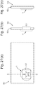
- Figures 2(a), (b) and (c) show three alternative profiles of the zone plate structure shown in Figure 1 along a radial direction (not to scale).
- the vertical axis may represent physical height h (in the case of a phase-difference device) or optical transparency T (in the case of an amplitude-difference device).
- h physical height
- T optical transparency
- the band profile is substantially sinusoidal. This is strongly preferred since this results in lower diffraction efficiency and hence greater angular spread of the different wavelengths, meaning a brighter and more colorful diffraction pattern is exhibited.
- the structure could alternatively have a square-wave profile as shown in Figure 2(b) , or a triangular profile as shown in Figure 2(c) , both of which would lead to higher diffraction efficiency such that the diffracted light will be more closely focussed.
- the triangular profile shown in the Figure 2(c) it will be noted that the outer flank of each triangular "peak" is curved and its gradient increases with increasing radius r.
- the outer flanks of the peaks in Figure 2(c) reconstruct the shape of the spherical surface on which the zone structure is based, as in conventional (reflective / refractive) Fresnel structures.
- Figures 3(a) and (b) are images showing the appearance of the first diffraction pattern 5 exhibited by a first diffractive structure 2 of the sort shown in Figure 1 when illuminated by white light.
- the first diffraction pattern will be visible at substantially all viewing angles (i.e. over essentially the whole viewing hemisphere), but its appearance will vary upon changes in tilt angle about the x- or y-axes.
- Figure 3(a) shows the appearance of the first diffraction pattern 5 at a first viewing angle
- Figure 3(b) shows its appearance at a second, different viewing angle.
- the first diffraction structure is rotationally symmetric, the light image presented to the viewer will appear constant and invariant when the device is simply rotated about the z-axis (azimuthal axis) without any change in tilt angle (see Figure 6 below for definitions of these angles), although the diffraction pattern is still moving with respect to the reference frame of the carrier. Since the device will always have some identifiable reference feature (such as a corner of the carrier, an article to which the carrier is attached or even the point at which the user is holding the device), this will be apparent as relative motion between the diffraction pattern and that reference feature since the pattern will appear to stay stationary as the object displaying it is rotated.
- some identifiable reference feature such as a corner of the carrier, an article to which the carrier is attached or even the point at which the user is holding the device
- the diffraction pattern comprises one or more bright areas 6 and a background 7 which is less bright and more blurred. Whilst the Figures are necessarily shown in greyscale, it should be appreciated that the real appearance is multi-coloured, each of the bright portions 6 displaying a rainbow spectrum of different colours (possibly with multiple repeats) emanating from the point P towards the edge of the device 1.
- the bright portions 6 can be described as forward-projecting and reverse-projecting light beams whose boundaries trace out a spherical surface around the device with a radius equalling the constant f in the expression given above. As the viewing angle is changed, e.g. by tilting and/or rotating the device 1, the bright areas 6 appear to move relative to the point P, e.g.
- Diffractive zone plate structures based on surfaces with circular curvature are particularly preferred for use in the presently disclosed devices.
- alternative zone plate structures that could be used include those based on cylindrical surfaces, ellipsoids, toroids, or any portion thereof.
- Figure 4 shows an example of a zone plate structure 2 based on a cylindrical surface, the long axis of the cylinder being aligned with the y-axis.
- the structure 2 comprises a series of spaced bands as before, except here they are straight and parallel to one another.
- the structure is symmetric about line P which corresponds to the central axis of the cylinder, and the spacing of the bands decreases with distance r from the line P in accordance with the same relationship already described above.
- the resulting diffraction pattern will be similar to that shown in Figure 3 except here the bright portions 6 will appear to emanate from along the whole length of reference line P, covering rectangular or parallelogram-shaped areas of the device which vary depending on the viewing angle. Again, the line P will be discernible as a fixed line in the diffraction pattern relative to which other features of the pattern move on tilting of the device. However since the curvature of the cylinder is only in one axis, the movement will only be apparent upon tilting in the direction of the axis and not upon tilting in the perpendicular direction.
- Figure 5 shows an example of a zone plate structure 3 based on an ellipsoid, having its long axis aligned with the y-axis and its short axis aligned with the x-axis.
- the structure 2 again comprises a series of spaced bands in the form of concentric ellipses centred on point P.
- the spacing of the bands is again governed by the expression given above, but here will also vary depending on the direction of r (i.e. the constant f in the above expression will have different values along the x- and y-axes, and each direction inbetween).
- the resulting diffraction pattern will be similar to that of Figure 3 , except for a corresponding elliptical distortion.
- the point P will act as a fixed reference point.
- Combinations of curved surfaces could also be used, e.g. two abutting cylindrical surfaces with different directions of their long axes (preferably orthogonal directions). In this case at least one portion of the device would exhibit movement upon tilting in any direction.
- FIG. 6 is a diagram illustrating the conventions that will be used below when referencing different viewing angles.
- An exemplary security device 1 is shown in a perspective view, lying in the plane defined by the x- and y-axes. The normal to that plane is the z-axis.
- on-axis light I will be redirected and an observer O at any one viewing position will see diffracted light D, the nature of which will depend on the diffraction structure and on the viewing position.
- the angle between the viewer O and the normal (z-axis) is referred to as the tilt angle, denoted by ⁇ (theta), since this will change if the device is tilted about the x-axis and/or the y-axis.
- the rotational position of the viewer O relative to the x- and y-axes is the azimuthal angle, denoted by ⁇ (phi), and will vary if the device is rotated about the z-axis.
- a change in viewing angle may comprise both a tilt (i.e. change in ⁇ ) and a rotation (i.e. change in ⁇ ), or could comprise just one or the other.
- the angle ⁇ can also be used to describe the direction of other features lying in the plane of the device as will be seen below.
- the device 1 comprises a first diffractive structure 2 of the sort already described with reference to Figures 1 to 3 above, and a second diffractive structure 13.
- the two diffractive structures are arranged in different respective regions of the device.
- Figure 7(a) is a schematic plan view of the device 1 illustrating the arrangement of the various regions: all of the white areas constitute first regions 11 in which the first diffractive device 2 is present, whilst each of the black areas constitute second regions 12 in which the second diffractive device 13 is present.
- the first and second regions 11, 12 are interspersed with one another across the device.
- each second region 12 takes the form of an outline of an octagon (although any other shape or other indicia could be used instead), a plurality of such outlines with decreasing size being arranged inside one another, spaced by first regions 11. All of the regions are concentric and centred on reference point P of the first diffractive structure.
- the second diffractive structure 13 is an off-axis diffractive structure meaning that on-axis incident light will be redirected to some off-axis position.
- suitable structures include off-axis holograms as well as diffraction gratings.
- the second diffraction structure as a whole i.e. taking into account all of the second regions 12
- the second diffraction structure as a whole is made up of a plurality of portions each having different properties.
- each portion of the second diffractive structure corresponds to a different one of the second regions 12 (i.e. each of the octagonal outlines contains one portion of the second diffractive structure 13, each having different properties from one another).
- this one-to-one correspondence between portions of the second diffractive structure is preferred but not essential.
- more than one second region 12 of the device could contain the same diffractive structure with the same properties (i.e. any one portion of the second diffractive structure may be present in more than one of the second regions 12) and/or any one second region 12 could contain more than one portion of the second diffractive structure (i.e. the properties of the second diffractive structure may not be constant across the whole of any one second region 12).
- the different properties of the various portions of the second diffractive structure 13 are configured such that each portion of the second diffractive structure 13 redirects incident light to a different sub-set of off-axis viewing angles (which sub-sets may or may not overlap one another). This has the result that the appearance of the second diffraction effect changes (relative to the reference frame of the carrier) according to the viewing angle.
- Figure 7(b) schematically illustrates the appearance of the device using a composite image in which multiple views taken from different viewing angles have been combined with the result that the diffracted light from all of the second regions 12 is visible simultaneously so all of the octagonal outlines are apparent (it will be appreciated that whilst all the octagons are shown as white in practice they typically appear in multiple different colours). This may or may not be possible in practice depending on the degree to which the sub-set of viewing angles over which each portion of the second diffractive device can be viewed overlap one another. If all of the sub-sets include at least one viewing angle which is common to all of them then all the portions will be visible simultaneously at that view point.
- each portion of the second diffractive device is preferably configured to direct a different wavelength of diffracted light (i.e. a different colour) to any one viewing position.
- a different wavelength of diffracted light i.e. a different colour
- the second regions may remain visible at substantially all viewing positions, such that the extent of the second diffractive effect remains constant as the device is tilted and/or rotated, it will undergo a progressive colour change, e.g. exhibiting distinct bands of different diffracted colours which appear to move either outward from the innermost second region 12 to the outermost second region 12, or vice versa, depending on the change in viewing angle.
- each of the octagonal outlines 12 may contain a diffraction grating structure with a different pitch (but same orientation).
- the pitches of the various portions may vary between about 0.5 microns to about 10 microns (more preferably between about 0.5 microns to about 3 microns, most preferably between about 1 and 3 microns) the pitch increasing from one region to the next in accordance with the order in which the regions 12 are arranged spatially on the device, in order to give rise to a steady progression of diffractive colours in a continuous sense across the device upon tilting.
- the sub-set of viewing angles over which each second region of the second diffraction pattern is visible overlap to a lesser amount or not at all so that, as the viewing angle is changed, different ones of the second regions diffract light to the viewer.
- the regions appear to turn "on” and “off' as the device is tilted and/or rotated, giving rise to the impression that the size, shape or position of the second diffractive effect is changing, i.e. an animation.
- Figures 7(c) and (d) show the appearance of the device at two different viewing angles. In the position shown in Figure 7(c) , only the four innermost second regions 12a to d direct light to the viewer and the outer second regions do not.
- the second diffractive effect appears only at the centre of the device.
- the inner second regions are no longer visible but now the outer second regions 12e to 12k diffract light to the viewer such that the second diffractive effect no longer appears at the centre of the device but only towards the periphery.
- some intermediate set of second regions will be visible. The result is the appearance of a contacting/expanding octagonal region as the viewing angle changes.
- each of the second regions 12 can be formed as a diffraction grating with different orientation (i.e. the grating lines of each second region making a different angle ⁇ with the x-axis).
- the two second regions which are furthest apart from one another will have grating orientations at substantially 90 degrees from one another whilst each intervening second region will have an intermediate orientation which varies in constant steps from one second region to the next across the device. Since each diffraction grating will spread different wavelengths of light across a range of viewing angles, a colour progression may accompany the animation effect even if the pitches of all the diffraction gratings are the same.
- both the pitch and the orientation of the diffraction gratings may vary from one second region to the next and an example of this will be given below.
- the first diffractive effect will also be visible across the device, by virtue of the first regions 11 being interspersed with the second regions 12, and remains so at substantially all viewing angles.
- the first diffractive effect appears as a background to the second diffractive effect.
- the first diffractive effect also exhibits movement upon changing of the viewing angle with the bright features 6 appearing to rotate around reference point P (this motion not being depicted in Figure 7 ).
- both diffractive effects will appear to actively change when the device is tilted and/or rotated.
- the two diffractive effects appear strongly integrated with one another. Moreover, any misregister between the two effects (as might be the case in a counterfeit device made by laminating two diffractive elements on top of one another) will be immediately apparent.
- the second regions 12 preferably collectively occupy no more than 50% of the surface area, still preferably no more than 30%. This enables a significant proportion of the first diffraction pattern to be viewed in between the second regions.
- Each second region 12 is preferably sufficiently large so as to be individually distinguishable to the naked eye.
- the octagonal outline regions 12 may each have a line thickness of at least 300 microns. If the first diffraction structure 2 is absent in the second regions 12, as is the case in some embodiments, this has the result that, even at viewing angles at which the second region 12 in question does not direct diffracted light to the viewer, the presence of the second region 12 will be visible as an interruption in the first diffraction pattern. Hence, the full extent of the second diffraction structure in all second regions 12 may be visible as a "ghost image" even at viewing angles where only parts of the second diffractive effect are intended to be seen.
- Figure 8 shows a second embodiment of a security device in which this effect is reduced.
- the first and second diffractive structures are arranged in respective regions 11, 12 as shown schematically in Figure 8(a) .
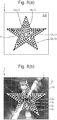
- there are four second regions 12a to 12d each having the form of the outline of a star centred on reference point P of the first diffraction pattern, and spaced from the next by the first region 11.
- the size of the outlines 12a to 12d increases such that they are nested inside one another.
- each second region 12a to 12d comprises a series of dot elements in which the second diffractive structure is present (shown in black, not individually labelled), interspersed with elements of the first diffractive structure 2 (shown in white).
- each second region 12a to 12d is an array of first elemental areas carrying the first diffractive structure 2 and an array of second elemental areas carrying the second diffractive structure 13.
- the elemental areas are formed at a scale too small to be individually discernible to the naked eye, e.g. having a width of 300 microns or less. It will be appreciated that, in the Figures, the individual elemental areas making up each second region 12a to 12d are shown at a much larger scale than will be the case in practice, for clarity.
- the second elemental areas carrying the second diffractive structure preferably take up no more than 50% of the area of the second region, to ensure good visibility of the first diffractive structure.
- each second region By forming each second region as a fine array of interspersed elemental areas of the first and second diffraction patterns on a scale too small for resolution by the naked eye, when a portion of the second diffraction pattern is not diffracting light to the viewer, its presence is less discernible (and preferably not discernible). As such the first diffraction pattern appears substantially without interruption and any "ghost image" is significantly less visible.
- each second region 12a to 12d has different properties, i.e. its second elemental areas correspond to a different portion of the second diffractive structure from those in another of the second regions.
- each second region 12a to 12d is visible at a different sub-set of viewing angles.
- Figure 8(b) is a composite image showing views of the device at several different viewing angles in combination, to illustrate the full extent of the second diffraction effect 15 against a background of the first diffraction pattern 5, although this may not be visible at any viewing angle in practice.
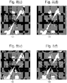
- the second diffractive structure preferably comprises a plurality of diffraction grating structures with different parameters, one in each of the second regions 12a to 12d.
- each second region has a different grating orientation (i.e. azimuthal angle ⁇ ), preferably varying across a 90 degree range, but constant grating pitch.
- ⁇ grating orientation
- the grating has a nominal orientation of zero degrees
- the grating has an orientation of 30 degrees
- the grating has an orientation of 60 degrees
- the outermost region 12c the grating has an orientation of 90 degrees.
- the grating pitch may be varied progressively from 0.6 microns in the innermost second region 12a to 1.2 microns in the outermost second region 12d.
- both the grating orientation and the pitch may be varied progressively from one second region to the next.
- the star appearing in the view shown in Figure 8(c) may appear yellow, that in Figure 8(d) green, that in Figure 8(e) blue and that in Figure 8(f) purple, for example.
- Figures 9 , 10 and 11 show further examples of security devices in which the same principles as already described in relation to Figures 7 and 8 are employed.
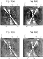
- Figures 9(a) to 9(d) show a security device in accordance with a third embodiment, from four different viewing angles.
- the second diffractive device exhibits an indicia, here the digit "5", and an outline of a cuboid.
- the digit "5" is positioned substantially on the reference point P of the first diffraction pattern and is formed of a second region 12x in which the second diffractive structure is configured to diffract light across a wide range of viewing angles, potentially substantially all viewing angles, so that it is visible from most points of view.
- the cuboid feature is made up of a plurality of outlines, each corresponding to a different second region 12a, 12b etc., each depicting the same cuboid but from a different perspective.
- Four of the outlines 12a, 12b, 12c and 12d are shown in Figures 9(a) to (d) respectively. More second regions exhibiting further outlines of the cuboid at other orientations could be provided but are not visible at the viewing angles depicted.
- the second diffractive structure is configured differently in each of the second regions, for instance comprising a diffraction grating with different orientation and/or pitch in each second region, so that as the device is tilted and/or rotated, different ones of the outlines become visible. This has the result that the cuboid appears to rotate around the static digit "5" (or other indicia) 12x.
- the first diffraction pattern 5 also exhibits motion as the viewing angle is changed as previously described.
- the cuboid appears to move at substantially the same speed and in the same direction as the bright features 6, giving the impression that there is no relative movement of the cuboid to the first diffraction pattern, although both will appear to move relative to the digit "5", and to any other reference point which is fixed relative to the reference frame of the carrier.
- each second region 12 may contain solely the second diffractive structure, in which case they will interrupt the first diffraction pattern, but preferably the first and second diffraction structures are combined in the second regions 12, e.g. by arranging each as an array of elemental areas in the manner described with reference to Figure 8 . Another option for combining the diffractive structures will be described below.
- Figure 10 shows a fourth embodiment of a security device as a composite image made up of views from multiple different viewing angles.
- the second diffractive device is arranged in a series of second regions 12a, 12b... each having the form of a concentric circle centred on the reference point P of the first diffraction pattern.
- Each concentric circle is formed as a broken line to maintain the visibility of the first diffraction pattern, and optionally each part of the broken line may be formed as an array of elemental areas in the manner described above to further reduce any "ghost image" effect.
- the second diffractive structure is configured differently in each of the concentric circles applying the same principles as above such that upon tilting and/or rotating, different ones of the circles become visible, resulting in an expansion/contraction effect, and/or the circles exhibit a progressive change in colour.
- Figure 11 shows a fifth embodiment of a security device as a composite image made up of views from multiple different viewing angles.
- the second diffractive device is arranged in a series of ellipses 12a to 12e with different orientations, each centred on the reference point P of the first diffraction pattern, intersecting one another as shown.
- a further second region 12x in the form of the digit "5" is provided at the centre, and is configured to remain substantially static upon tilting as in the Figure 9 embodiment.
- the elliptical second regions 12a to 12e are each provided with a different portion of the second diffractive structure with different properties such that, upon tilting, different ones of the ellipses become progressively visible.
- a subset of the ellipses is visible (e.g. one ellipse, or two orthogonal ellipses) and upon tilting this appears to rotate about the digit "5".
- the second regions could be configured such that the apparent motion of the ellipse(s) appears to track that of the bright features 6 in the first diffraction pattern.
- Figures 12 and 13 depict a sixth embodiment of a security device in which the second diffraction structure is configured such that different effects are exhibited upon different changes in viewing angle.
- Figure 12 is a composite image made up of views from multiple different viewing angles so that all parts of the second diffraction pattern 15 are visible against the first diffraction pattern 5.
- the second diffraction structure is provided in a pattern of second regions 12 which is arranged in four concentric rings.
- the innermost ring 12a comprises a set of eight star-shaped second regions arranged in a circle entered on the reference point P of the first diffraction pattern.
- the neighbouring ring 12b comprises eight second regions each having the shape of the digit "5".
- ring 12c comprises eight star-shaped second regions and finally outermost ring 12d comprises a further eight second regions each in the shape of a digit "5". It will be noted that the size of the second regions increases with distance from the reference point P and this is preferred since this gives the appearance of perspective which reinforces that suggested by the first diffraction pattern.
- the properties of the second diffractive structure (which preferably comprises a plurality of diffraction gratings) vary not only between each ring of symbols 12a, 12b etc., but also circumferentially from one second region to the next within each ring.
- the grating pitch is constant but the grating orientation (azimuthal angle ⁇ ) varies from one to the next, progressively in a clockwise direction.
- the grating pitch is again constant but different from that in innermost ring 12a.
- the grating orientation varies between the "5"s making up ring 12b clockwise in the same manner as in the innermost ring 12a, such that the second regions 12a, 12b lined up along any one radial direction all share the same grating orientation but vary in grating pitch.
- the second regions making up rings 12c and 12d vary in pitch according to their distance from the centre and in their grating orientation according to their position about the circumference of the arrangement.
- the outermost "5"s 12d may appear red (whilst the stars 12c remain yellow).
- view D When the device is tilted down (view D), now only the innermost ring 12a of stars and "5"s 12b are visible so the device appears to have contracted towards the centre.
- the innermost stars 12a appear in a still further colour, e.g. blue. Therefore, upon up-down tilting, the second diffractive effect appears to expand and contract about the centre point and also undergoes a colour change in step with the expansion/contraction effect.
- Each of the second regions 12a to 12d could contain the second diffraction structure only, or could contain the first and second diffraction structures in combination (using the method of Figure 8 or the alternative described below) to maintain the visibility of the first diffraction pattern.
- Figure 14 is a composite image made up of views from multiple different viewing angles so that all parts of the second diffraction pattern 15 are visible against the first diffraction pattern 5.
- Figures 14 and 15 comprise photographs of a real sample device and so the movement exhibited by the first diffraction pattern upon tilting is also visible. It will be noted that in this embodiment the majority of the first diffraction pattern 5 appears dark at any one viewing angle leaving only the bright features (here labelled 6', 6" and 6"') visible: this is due to the photographs having been taken under relatively narrow sources of light, rather than under ambient illumination (e.g.
- the second diffractive structure is provided in a series of second regions 12 which collectively form an image of a centurion's head as shown in Figure 14 .
- the individual second portions will be illustrated in Figure 13 .
- Each second portion is made up of an array of elemental areas in the form of dots, spaced by areas of the first diffraction pattern.
- the device is shown at a large size so that the elemental areas can be seen but in practice these will be on a scale too small for the naked eye to individually discern, or only upon close inspection.
- each dot element may have a diameter of 300 microns or less.
- the centurion's head as a whole appears coloured with a rainbow spectrum which varies continuously across the device, e.g. from top to bottom. This is due to the natural dispersion of wavelengths by the second diffractive device and is not linked to the animation effect described below.
- the outline showing the centurion's profile and helmet may be provided by one second region (or more than one concentric outline region), whilst the internal features such as the shading to the centurion's cheek and forehead may be provided by another (one or more) second region.
- Figure 15(a) shows the appearance of the device at substantially the normal viewing position. It will be seen that the second region 12a of the second diffractive structure which is visible forms an outline of the centurion, with no internal detail. The colour of the outline varies gradually from orange/yellow at the top to green/blue at the bottom, due to the natural dispersion effect of the diffraction grating.
- Figure 15(b) substantially the same second region 12a remains visible but becomes brighter as bright colours of the diffraction spectrum (red/orange) are directed to the viewer, resulting also in an apparent increase in the width of the outline.
- a first diffractive structure in the form of a circular zone plate has been used in each case and as such the second diffractive structures have generally been designed to include circular rotational symmetry and/or to exhibit changes towards or away from the reference point of the first diffractive structure.
- the second diffractive structure is preferably designed so as to appear visually integrated with the displayed first diffraction pattern.
- the first diffraction pattern is based on a cylindrical surface and hence has a reference line rather than a reference point
- the second diffractive structure may be configured to exhibit motion (or a colour change) along the same direction as the reference line. This can be achieved by arranging suitably configured second regions 12 spaced along the relevant direction.
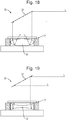
- Figures 16 and 17 schematically illustrate various alternative approaches for incorporating the first and second diffractive structures 2, 13, into the device.
- Figure 16 shows a part of a device 1 which includes two second portions 12a, 12b in which the second diffractive structure is present, spaced and surrounded by a first region 11 in which the first diffractive structure is present.
- Figures 17(a) to (c) show three alternative cross-sections through the device 1 along the line X-X'. It will be appreciated that the cross-sections are schematic and not shown to scale.
- the first diffractive structure 2 is of the same type as already discussed with respect to Figures 1 and 2 and in this case a sinusoidal profile shape is adopted.
- the surface relief of the carrier follows the form of the first diffractive structure 2 across the whole of first region 11.
- the second regions 12 can be implemented in different ways. In a first option, shown in Figure 17(a) , within the second regions 12a, 12b, the first diffractive structure 2 (shown in dashed lines) is entirely replaced by the second diffractive structure 13. This was the case in the Figure 7 embodiment discussed above and as previously mentioned gives rise to interruptions in the first diffraction pattern which may appear as a "ghost image" of the second diffractive structure.
- Figure 17(c) shows the technique adopted in the Figure 8 embodiment for reducing this effect.
- the first diffractive structure 2 is present in a first array of elemental areas 16 which are interspersed with a second array of elemental areas 17 in which the second diffractive structure 13 is present.
- the elemental areas are provided on a scale too small for the naked eye to resolve, e.g. 300 microns or less.
- the fill factor of the second elemental areas 17 is 50% or less.
- FIG. 17(b) An alternative method for avoiding "ghost images" is shown in Figure 17(b) .
- the first and second diffractive patterns are combined in the second regions 12a, 12b by superimposing the second diffractive structure 13 on top of the first diffractive structure 2.
- the peaks of the first diffractive structure are effectively modified in the second regions according to the second diffractive structure (as shown in Figure 17(b) , it should be noted that the modification will typically extend down the flanks of the peaks as well as the tops).
- the profile depth of the second diffractive structure should be smaller than that of the first diffractive structure. In this way, the diffractive efficiency of the two diffractive structures can be balanced against one another in the second regions so that both can be visualised.
- the exposure energy required to ensure that the off axis diffractive structure develops a grating peak to trough amplitude which maximises the diffractive replay efficiency for a development time T is E1 (giving a peak to trough depth of approximately ⁇ /3n, where ⁇ is a visible light wavelength and n is the refractive index of the carrier), and the exposure energy required to ensure that the Fresnel zone structure develops a peak to trough amplitude which maximises its respective diffractive replay efficiency for the same development time T is E2.
- the first and second diffractive structures can be generated in various ways.
- Figures 18 and 19 show two possible recording geometries for holographic generation of a diffractive zone plate structure suitable for use as the first diffractive structure in any of the presently disclosed embodiments.
- a resist layer 31 (optionally supported on a transparent substrate) is placed in near contact with an object having a continuously curved reflecting surface of the desired shape. In the present case this is provided by a spherical converging lens 32 (which may be coated with a reflective material such as metal on its reverse side).
- a collimated beam of laser light L is then arranged to fall on this combination parallel to the optical axis of the lens 32 (e.g.
- the process can be adapted to record zone plate structures from any desired curved surface by replacing the lens 32 with an appropriately shaped reflecting surface.
- Figure 19 shows the use of a bi-concave lens 32' to create a Fresnel zone plate structure of a diverging lens.
- the lens 32, 32' could be replaced by a cylindrical lens to create a cylindrical zone structure as shown in Figure 4 , or by an ellipsoidal surface to create the zone structure shown in Figure 5 .
- Figure 20 schematically illustrates the use of an optical fringe writer 35 in which collimated laser light L is focussed by optics 36 onto the resist plate 31.
- the fringe writer is controlled to move the laser beam in accordance with the desired pattern to which the resist is to be exposed. This will be determined by mathematically modelling the interference pattern that would generated by the desired continuously curved surface (e.g.
- the first diffractive structure 2 may be formed across the whole resist layer 31 and then modified or destroyed in the second regions 12 by the introduction of the second diffractive structure 13. As described with reference to Figures 17(a) to (c) , this could involve replacing the whole of the first diffraction structure across each second region with the second diffraction structure, or superimposing the second diffraction structure on top of the first diffraction structure, or replacing the first diffraction structure with the second only in an array of elemental areas 17 within each second region 12.
- the resulting surface relief can be transferred into a suitable carrier, e.g. by embossing or cast-curing as mentioned above.
- a reflection enhancing layer such as metal or a high refractive index material (e.g. ZnS) will be applied onto the carrier in such a way as to conform to the contours of the surface relief, preferably on both sides of the reflection enhancing layer so that the diffraction patterns can be viewed from both sides of the device.
- a metal layer of aluminium, copper, chromium or the like may be applied to the surface relief by vapour deposition or similar.
- a reflective ink e.g. metallic ink
- the layer 52 could also act as a resist layer.
- the layer 52 could be selectively applied to certain areas only of the device (e.g. by printing), resulting in gaps 53 which preferably define an image.
- the patterned layer 52 can then be used as an etch resist such that portions of the reflection enhancing layer 51 corresponding to each of the gaps are removed, resulting in a demetallised image.
- the security device 1 may be formed by cast-curing a suitable carrier material 50 onto the substrate 102, in which the desired relief structure is formed.
- the security device 1 may have been formed separately on a security article such as a transfer patch or label.
- the security device 1 may be affixed to the transparent substrate 102 inside the window region 101 by means of a suitable adhesive.
- Application may be achieved by a hot or cold transfer method e.g. hot stamping.
- a similar construction could be achieved using a paper/plastic composite banknote in which the opacifying layers 103a and 103b are replaced by paper layers laminated (with or without adhesive) to an internal transparent polymer layer 102.
- the paper layers may be omitted from the window region from the outset, or the paper could be removed locally after lamination.
- the order of the layers may be reversed with a (windowed) paper layer on the inside and transparent polymer layers on the outside.
- Security devices of the sort disclosed herein are particularly well suited to application to documents with polymer substrates such as that shown in Figure 26 since zone plate structures such as those used to form the first diffractive structure replay particularly well when they are supported on a flat, smooth surface.
- the surface of a polymer substrate is typically smoother than those of conventional, e.g. paper substrates.
- the banknote 100 is of conventional construction having a substrate 102 formed for example of paper or other relatively opaque or translucent material.
- the window region 101 is formed as an aperture through the substrate 102.
- the security device 1 is applied as a patch overlapping the edges of window 101 utilising an adhesive to join the security article to the document substrate 102.
- the application of the security device and document could be achieved using various methods including hot stamping.
- Figure 27(b) shows a variant in which the window 101 is omitted and the device 1 is simply applied to a section of the substrate 102 using any convenient application technique such as hot stamping. In such arrangements the device 1 will of course only be viewable from one side of the security document 100.
- Figure 28 depicts a third example of a security document, again a banknote 100, to which a security article 105 in the form of a security thread or security strip has been applied.
- Three security devices 1 each carried on the strip 105 are revealed through windows 101, arranged in a line on the document 100.
- Two alternative constructions of the document are shown in cross-section in Figures 28(b) and 28(c).
- Figure 28(b) depicts the security thread or strip 105 incorporated within the security document 100, between two portions of the document substrate 102a, 102b.
- the security thread or strip 105 may be incorporated within the substrate's structure during the paper making process using well known techniques.
- the paper may be removed locally after completion of the paper making process, e.g.
- FIG. 28(c) shows an alternative arrangement in which the security thread or strip 105 carrying the security device 1 is applied to one side of document substrate 102, e.g. using adhesive.
- the windows 101 are formed by the provision of apertures in the substrate 102, which may exist prior to the application of strip 105 or be formed afterwards, again for example by abrasion.
- security documents of the sorts discussed above are known and could be used.
- the above described device structures could be formed on other types of security document including identification cards, driving licenses, bankcards and other laminate structures, in which case the security device may be incorporated directly within the multilayer structure of the document.
Landscapes
- Physics & Mathematics (AREA)
- Engineering & Computer Science (AREA)
- Manufacturing & Machinery (AREA)
- General Physics & Mathematics (AREA)
- Accounting & Taxation (AREA)
- Business, Economics & Management (AREA)
- Finance (AREA)
- Optics & Photonics (AREA)
- Computer Security & Cryptography (AREA)
- Health & Medical Sciences (AREA)
- Electromagnetism (AREA)
- General Health & Medical Sciences (AREA)
- Toxicology (AREA)
- Diffracting Gratings Or Hologram Optical Elements (AREA)
- Credit Cards Or The Like (AREA)
Claims (17)
- Dispositif de sécurité diffractif comprenant des première et seconde structures diffractives définies dans une couche porteuse, la première structure diffractive (2) étant une structure de plaque de zone diffractive d'une surface incurvée en continu conçue de telle sorte que lorsque le dispositif est éclairé par une lumière sur axe, un premier motif de diffraction généré par la première structure diffractive peut être visualisé depuis au moins un premier côté du dispositif à pratiquement tous les angles de visualisation, le premier motif de diffraction présentant un point de référence ou une ligne de référence par rapport auxquels d'autres caractéristiques du premier motif de diffraction semblent se déplacer lorsque l'angle de visualisation est modifié ; et
la seconde structure diffractive (13) étant une structure diffractive hors axe conçue de telle sorte que lorsque le dispositif est éclairé par une lumière sur axe, un second motif de diffraction généré par la seconde structure diffractive peut être visualisé depuis au moins le premier côté du dispositif au niveau d'au moins certains angles de visualisation hors axe, la seconde structure diffractive comprenant une pluralité de parties décalées latéralement, chaque partie de la seconde structure diffractive étant conçue de telle sorte que, lorsque le dispositif est éclairé par une lumière sur axe, la partie du second effet de diffraction généré par la partie respective de la seconde structure diffractive ne peut être visualisée que depuis un sous-ensemble respectif d'un ou de plusieurs angles de visualisation hors axe prédéterminés, les sous-ensembles respectifs des angles de visualisation étant différents pour les différentes parties de la seconde structure diffractive de telle sorte que, lorsque l'angle de visualisation est modifié, différentes parties du second dispositif diffractif diffractent la lumière à l'observateur en séquence, moyennant quoi le second effet de diffraction semble se déplacer ;
le dispositif comportant une ou plusieurs premières régions (11) dans lesquelles la première structure diffractive est présente, mais pas la seconde structure diffractive, et le dispositif comporte une ou plusieurs secondes régions (12) dans lesquelles la seconde structure diffractive est présente, la première structure diffractive étant éventuellement présente et combinée avec la seconde structure diffractive dans les secondes régions, les première et seconde régions étant interposées l'une à l'autre dans le dispositif, de telle sorte que le premier motif de diffraction est présenté dans le dispositif au niveau de tous les angles de visualisation et au niveau d'au moins certains angles de visualisation, le second motif de diffraction semble superposé au premier motif de diffraction et lors de la modification de l'angle de visualisation, le second motif de diffraction présente une modification référencée par rapport au point de référence ou à la ligne de référence du premier motif de diffraction. - Dispositif de sécurité diffractif selon la revendication 1, dans lequel la première structure diffractive est une structure de plaque de zone diffractive d'un dôme, d'un hémisphère, d'un hémi-ellipsoïde, d'un demi-cylindre, d'un demi-tore ou d'une partie de ceux-ci.
- Dispositif de sécurité diffractif selon l'une quelconque des revendications précédentes, dans lequel la structure de plaque de zone diffractive est une structure de plaque à zone de différence de phase formée en tant que relief de surface dans la couche porteuse, le dispositif de sécurité diffractif comprenant en outre, de préférence, une couche d'amélioration de réflexion suivant les contours du relief de surface sur la couche porteuse.
- Dispositif de sécurité diffractif selon l'une quelconque des revendications précédentes, dans lequel la seconde structure diffractive est conçue de telle sorte que, lors d'une modification de l'angle de visualisation, au moins certaines de ses parties présentent un changement au niveau de la couleur de la lumière diffractée dirigée vers l'observateur, le changement de couleur se produisant progressivement d'une partie à la suivante de telle sorte que les couleurs diffractées de la seconde structure diffractive semblent se déplacer par rapport au point ou à la ligne de référence du premier motif de diffraction.
- Dispositif de sécurité diffractif selon l'une quelconque des revendications précédentes, dans lequel la seconde structure diffractive est conçue de telle sorte que, lors d'une modification de l'angle de visualisation, au moins certaines de ses parties dirigent à leur tour la lumière diffractée vers l'observateur, le second effet de diffraction devenant visible dans chacune de la pluralité des secondes régions dans la même séquence que l'ordre dans lequel les secondes régions sont disposées spatialement sur le dispositif, de telle sorte que la position et/ou l'étendue du second motif de diffraction semble se déplacer par rapport au point ou à la ligne de référence du premier motif de diffraction.
- Dispositif de sécurité diffractif selon l'une quelconque des revendications précédentes, dans lequel chacune de la pluralité de parties de la seconde structure diffractive comprend une structure de réseau de diffraction, les paramètres de la structure de réseau de diffraction dans chaque partie étant différents, de préférence le pas de la structure de réseau de diffraction et/ou l'orientation de la structure de réseau de diffraction étant différents dans chaque partie, et éventuellement les parties de la seconde structure de diffraction étant disposées dans les secondes régions du dispositif, de telle sorte que les paramètres du réseau changent progressivement d'une seconde région à la suivante, selon le même ordre que celui dans lequel les secondes régions sont disposées spatialement dans le dispositif.
- Dispositif de sécurité diffractif selon l'une quelconque des revendications précédentes, dans lequel les secondes régions du dispositif sont disposées de manière à définir des indices ou un motif qui entoure, et de préférence est centré sur, le point ou la ligne de référence du premier motif de diffraction, et éventuellement les secondes régions comprenant au moins deux zones espacées définissant chacune différentes parties respectives des indices ou motifs, et la seconde structure diffractive étant conçue de telle sorte que différentes zones des au moins deux zones espacées orientent la lumière diffractée vers l'observateur sous différents angles de visualisation, moyennant quoi différentes parties des indices ou du motif sont visibles lorsque l'angle de visualisation est modifié, de préférence, au niveau d'au moins un angle de visualisation, toutes les parties des indices ou du motif étant simultanément visibles.
- Dispositif de sécurité diffractif selon l'une quelconque des revendications précédentes, dans lequel les première et seconde structures diffractives sont combinées dans les secondes régions et conçues de telle sorte que, lorsque le dispositif est visualisé depuis l'un des sous-ensembles d'angles de visualisation hors axe prédéterminés auxquels le second effet de diffraction est visible dans au moins une seconde région, le dispositif présente le premier effet de diffraction dans la ou les premières régions et le second effet de diffraction dans l'au moins une seconde région, et lorsque le dispositif est visualisé depuis un angle de visualisation différent auquel le second effet de diffraction n'est pas visible dans l'au moins une seconde région, le dispositif présente le premier effet de diffraction dans la ou les premières régions et dans l'au moins une seconde région sans pratiquement de contraste entre les premières régions et l'au moins une seconde région.
- Dispositif de sécurité diffractif selon la revendication 8, dans lequel au sein de ou pour chaque seconde région du dispositif :la première structure diffractive n'est présente que dans un premier réseau de zones élémentaires, et la seconde structure diffractive n'est présente que dans un second réseau de zones élémentaires, les zones élémentaires du premier réseau étant interposées avec les zones élémentaires du second réseau, les zones élémentaires des premier et second réseaux étant suffisamment petites pour qu'elles ne puissent être individuellement détectables à l'oeil nu ; oules première et seconde structures diffractives sont superposées l'une sur l'autre, la seconde structure diffractive modifiant la première structure diffractive.
- Procédé de fabrication d'un dispositif de sécurité diffractif, comprenant la formation des première et seconde structures diffractives dans une couche porteuse, la première structure diffractive (2) étant une structure de plaque de zone diffractive d'une surface incurvée en continu conçue de telle sorte que lorsque le dispositif est éclairé par une lumière sur axe, un premier motif de diffraction généré par la première structure diffractive peut être visualisé depuis au moins un premier côté du dispositif à pratiquement tous les angles de visualisation, le premier motif de diffraction présentant un point de référence ou une ligne de référence par rapport auxquels d'autres caractéristiques du premier motif de diffraction semblent se déplacer lorsque l'angle de visualisation est modifié ; et
la seconde structure diffractive (13) étant une structure diffractive hors axe conçue de telle sorte que lorsque le dispositif est éclairé par une lumière sur axe, un second motif de diffraction généré par la seconde structure diffractive peut être visualisé depuis au moins le premier côté du dispositif au niveau d'au moins certains angles de visualisation hors axe, la seconde structure diffractive comprenant une pluralité de parties décalées latéralement, chaque partie de la seconde structure diffractive étant conçue de telle sorte que, lorsque le dispositif est éclairé par une lumière sur axe, la partie du second effet de diffraction généré par la partie respective de la seconde structure diffractive ne peut être visualisée que depuis un sous-ensemble respectif d'un ou de plusieurs angles de visualisation hors axe prédéterminés, les sous-ensembles respectifs des angles de visualisation étant différents pour les différentes parties de la seconde structure diffractive de telle sorte que, lorsque l'angle de visualisation est modifié, différentes parties du second dispositif diffractif diffractent la lumière à l'observateur en séquence, moyennant quoi le second effet de diffraction semble se déplacer ;
le dispositif comportant une ou plusieurs premières régions (11) dans lesquelles la première structure diffractive est présente, mais pas la seconde structure diffractive, et le dispositif comporte une ou plusieurs secondes régions (12) dans lesquelles les première et seconde structures diffractives sont combinées l'une à l'autre, les première et seconde régions étant interposées l'une à l'autre dans le dispositif, de telle sorte que le premier motif de diffraction est présenté dans le dispositif au niveau de tous les angles de visualisation et au niveau d'au moins certains angles de visualisation, le second motif de diffraction semble superposé au premier motif de diffraction et lors de la modification de l'angle de visualisation, le second motif de diffraction présente une modification référencée par rapport au point de référence ou à la ligne de référence du premier motif de diffraction. - Procédé de fabrication d'un dispositif de sécurité diffractif selon la revendication 10, dans lequel les première et seconde structures diffractives sont formées par :la fourniture d'un outil de réplication ayant un relief de surface définissant les première et seconde structures diffractives ; etl'utilisation de l'outil de réplication pour former la surface de la couche porteuse en fonction du relief de surface, et de préférence,l'application d'une couche améliorant la réflexion sur la couche porteuse afin de suivre les contours du relief de surface.
- Procédé de fabrication d'un dispositif de sécurité diffractif selon la revendication 11, dans lequel l'outil de réplication est fabriqué en créant le relief de surface dans une couche de support d'enregistrement et en transférant de préférence le relief de surface à la surface de l'outil de réplication.
- Procédé de fabrication d'un dispositif de sécurité diffractif selon la revendication 12, dans lequel le relief de surface est créé dans une couche de support d'enregistrement en formant une première structure à relief de surface correspondant à la première structure diffractive, puis dans les secondes régions du dispositif modifiant ou détruisant la première structure à relief de surface en formant une seconde structure à relief de surface correspondant à la seconde structure diffractive, de préférence:la première structure à relief de surface étant générée de façon holographique en exposant la couche de support d'enregistrement à un diagramme d'interférence de lumière depuis la surface incurvée en continu ; oula première structure à relief de surface étant formée à l'aide d'un graveur de franges optiques ou d'une lithographie par faisceau d'électrons.
- Procédé de fabrication d'un dispositif de sécurité diffractif selon la revendication 13, dans lequel:la seconde structure à relief de surface est générée de façon holographique en exposant la couche de support d'enregistrement à un diagramme d'interférence de lumière depuis un hologramme de transmission hors axe ; oula seconde structure à relief de surface est formée à l'aide d'un graveur de franges optiques ou d'une lithographie par faisceau d'électrons.
- Procédé de fabrication d'un dispositif de sécurité diffractif selon la revendication 12, dans lequel le relief de surface est créé dans une couche de support d'enregistrement en combinant numériquement une première structure à relief de surface correspondant à la première structure diffractive et une seconde structure à relief de surface correspondant à la seconde structure diffractive, de telle sorte que dans les secondes régions du dispositif, la première structure à relief de surface est modifiée ou détruite et forme la surface de la couche de support d'enregistrement en fonction du relief de surface combiné, de préférence à l'aide d'un graveur de franges optiques ou d'une lithographie par faisceau d'électrons.
- Article de sécurité comprenant un dispositif de sécurité selon l'une quelconque des revendications 1 à 9, de préférence, un fil, une bande, un patch, une feuille, une feuille de transfert ou un insert.
- Document de sécurité comprenant un dispositif de sécurité selon l'une quelconque des revendications 1 à 9, ou un article de sécurité selon la revendication 16, le document de sécurité comprenant de préférence un billet de banque, un document d'identité, un passeport, un chèque, un visa, un permis, un certificat ou un tampon.
Applications Claiming Priority (2)
| Application Number | Priority Date | Filing Date | Title |
|---|---|---|---|
| GB1513094.1A GB2545387A (en) | 2015-07-24 | 2015-07-24 | Security device and method of manufacturing thereof |
| PCT/GB2016/052224 WO2017017418A1 (fr) | 2015-07-24 | 2016-07-22 | Dispositif de sécurité et son procédé de fabrication |
Publications (2)
| Publication Number | Publication Date |
|---|---|
| EP3325281A1 EP3325281A1 (fr) | 2018-05-30 |
| EP3325281B1 true EP3325281B1 (fr) | 2019-09-04 |
Family
ID=54106580
Family Applications (1)
| Application Number | Title | Priority Date | Filing Date |
|---|---|---|---|
| EP16744481.9A Active EP3325281B1 (fr) | 2015-07-24 | 2016-07-22 | Dispositif de sécurité et son procédé de fabrication |
Country Status (5)
| Country | Link |
|---|---|
| US (1) | US10632779B2 (fr) |
| EP (1) | EP3325281B1 (fr) |
| AU (1) | AU2016299393A1 (fr) |
| GB (1) | GB2545387A (fr) |
| WO (1) | WO2017017418A1 (fr) |
Families Citing this family (7)
| Publication number | Priority date | Publication date | Assignee | Title |
|---|---|---|---|---|
| DE102017106433A1 (de) | 2017-03-24 | 2018-09-27 | Ovd Kinegram Ag | Sicherheitselement und Verfahren zur Herstellung eines Sicherheitselements |
| BG67098B1 (bg) * | 2017-05-03 | 2020-06-30 | „Демакс Холограми“ Ад | Променлив оптичен елемент |
| GB2584552B (en) * | 2017-10-19 | 2021-07-21 | De La Rue Int Ltd | Security devices, security articles, security documents and methods for their manufacture |
| GB2567811B (en) * | 2017-10-19 | 2020-06-17 | De La Rue Int Ltd | Security devices, security articles, security documents and methods for their manufacture |
| DE102021001899A1 (de) * | 2021-04-13 | 2022-10-13 | Giesecke+Devrient Currency Technology Gmbh | Optisch variables sicherheitselement und wertdokument mit dem optisch variablen sicherheitselement |
| DE102021001898A1 (de) * | 2021-04-13 | 2022-10-13 | Giesecke+Devrient Currency Technology Gmbh | Optisch variables sicherheitselement und wertdokument mit dem optisch variablen sicherheitselement |
| SE2150453A1 (en) * | 2021-04-13 | 2022-10-14 | Rolling Optics Innovations Ab | Synthetic images with animation of perceived depth |
Family Cites Families (12)
| Publication number | Priority date | Publication date | Assignee | Title |
|---|---|---|---|---|
| US5886798A (en) * | 1995-08-21 | 1999-03-23 | Landis & Gyr Technology Innovation Ag | Information carriers with diffraction structures |
| US8769359B2 (en) * | 2001-02-15 | 2014-07-01 | Syntest Technologies, Inc. | Multiple-capture DFT system for detecting or locating crossing clock-domain faults during self-test or scan-test |
| DE10127979C1 (de) * | 2001-06-08 | 2002-11-07 | Ovd Kinegram Ag Zug | Diffraktives Sicherheitselement |
| DE10254499B4 (de) * | 2002-11-22 | 2005-12-22 | Ovd Kinegram Ag | Schichtanordnung mit einer einen linsenartigen Effekt erzeugenden beugungsoptisch wirksamen Struktur |
| DE102004044458B4 (de) * | 2004-09-15 | 2010-01-07 | Ovd Kinegram Ag | Sicherheitsdokument |
| DE102005062132A1 (de) * | 2005-12-23 | 2007-07-05 | Giesecke & Devrient Gmbh | Sicherheitselement |
| US8488242B2 (en) * | 2006-06-20 | 2013-07-16 | Opsec Security Group, Inc. | Optically variable device with diffraction-based micro-optics, method of creating the same, and article employing the same |
| DE102006037431A1 (de) | 2006-08-09 | 2008-04-17 | Ovd Kinegram Ag | Verfahren zur Herstellung eines Mehrschichtkörpers sowie Mehrschichtkörper |
| GB0711434D0 (en) | 2007-06-13 | 2007-07-25 | Rue De Int Ltd | Holographic security device |
| WO2010121293A1 (fr) * | 2009-04-21 | 2010-10-28 | Securency International Pty Ltd | Dispositif optiquement variable et document de sécurité le comprenant |
| DE102011014114B3 (de) * | 2011-03-15 | 2012-05-10 | Ovd Kinegram Ag | Mehrschichtkörper und Verfahren zur Herstellung eines Mehrschichtkörpers |
| FR2979734B1 (fr) * | 2011-09-02 | 2014-05-23 | Arjowiggins Security | Structure de securite comportant une structure optique reflechissante, et procede associe. |
-
2015
- 2015-07-24 GB GB1513094.1A patent/GB2545387A/en not_active Withdrawn
-
2016
- 2016-07-22 AU AU2016299393A patent/AU2016299393A1/en not_active Abandoned
- 2016-07-22 WO PCT/GB2016/052224 patent/WO2017017418A1/fr not_active Ceased
- 2016-07-22 US US15/746,229 patent/US10632779B2/en active Active
- 2016-07-22 EP EP16744481.9A patent/EP3325281B1/fr active Active
Non-Patent Citations (1)
| Title |
|---|
| None * |
Also Published As
| Publication number | Publication date |
|---|---|
| GB201513094D0 (en) | 2015-09-09 |
| EP3325281A1 (fr) | 2018-05-30 |
| WO2017017418A1 (fr) | 2017-02-02 |
| GB2545387A (en) | 2017-06-21 |
| US20180215189A1 (en) | 2018-08-02 |
| US10632779B2 (en) | 2020-04-28 |
| AU2016299393A1 (en) | 2018-02-15 |
Similar Documents
| Publication | Publication Date | Title |
|---|---|---|
| EP3325282B1 (fr) | Dispositif de sécurité à diffraction et son procédé de fabrication | |
| EP3325281B1 (fr) | Dispositif de sécurité et son procédé de fabrication | |
| US11077700B2 (en) | Multilayer body | |
| JP5101600B2 (ja) | 体積ホログラムを有する多層体 | |
| JP6068145B2 (ja) | モアレ拡大素子 | |
| AU2017250018B2 (en) | Micro-optic device with integrated focusing element and image element structure | |
| JP4601008B2 (ja) | 光学的セキュリティ素子 | |
| JP6550338B2 (ja) | セキュリティ装置 | |
| AU2013283489A1 (en) | Decorative element and security document comprising a decorative element | |
| JP2011510339A (ja) | フィルムエレメント | |
| US20250346059A1 (en) | Optically variable element, security document, method for producing an optically variable element, method for producing a security document | |
| CN104249597A (zh) | 一种光学防伪元件 | |
| JP2015068849A (ja) | 表示体及びラベル付き物品 | |
| JP4428559B2 (ja) | 光回折構造による隠しパターンを内包する表示体 | |
| US20200150586A1 (en) | Holographic security device and method of manufacture thereof | |
| JP4270438B2 (ja) | 光回折構造による隠しパターンを内包する表示体 | |
| CA3225441A1 (fr) | Composants optiques de securite, fabrication de tels composants et documents securises equipes de tels composants | |
| JP5754585B2 (ja) | 回折格子記録媒体 |
Legal Events
| Date | Code | Title | Description |
|---|---|---|---|
| STAA | Information on the status of an ep patent application or granted ep patent |
Free format text: STATUS: THE INTERNATIONAL PUBLICATION HAS BEEN MADE |
|
| PUAI | Public reference made under article 153(3) epc to a published international application that has entered the european phase |
Free format text: ORIGINAL CODE: 0009012 |
|
| STAA | Information on the status of an ep patent application or granted ep patent |
Free format text: STATUS: REQUEST FOR EXAMINATION WAS MADE |
|
| 17P | Request for examination filed |
Effective date: 20180122 |
|
| AK | Designated contracting states |
Kind code of ref document: A1 Designated state(s): AL AT BE BG CH CY CZ DE DK EE ES FI FR GB GR HR HU IE IS IT LI LT LU LV MC MK MT NL NO PL PT RO RS SE SI SK SM TR |
|
| AX | Request for extension of the european patent |
Extension state: BA ME |
|
| DAV | Request for validation of the european patent (deleted) | ||
| DAX | Request for extension of the european patent (deleted) | ||
| RIC1 | Information provided on ipc code assigned before grant |
Ipc: B42D 25/324 20140101ALI20190131BHEP Ipc: B42D 25/21 20140101ALI20190131BHEP Ipc: B42D 25/373 20140101ALI20190131BHEP Ipc: G02B 5/18 20060101ALI20190131BHEP Ipc: G07D 7/00 20160101ALI20190131BHEP Ipc: B42D 25/435 20140101ALI20190131BHEP Ipc: B42D 25/425 20140101AFI20190131BHEP Ipc: B42D 25/29 20140101ALI20190131BHEP Ipc: B42D 25/328 20140101ALI20190131BHEP |
|
| GRAP | Despatch of communication of intention to grant a patent |
Free format text: ORIGINAL CODE: EPIDOSNIGR1 |
|
| STAA | Information on the status of an ep patent application or granted ep patent |
Free format text: STATUS: GRANT OF PATENT IS INTENDED |
|
| INTG | Intention to grant announced |
Effective date: 20190404 |
|
| GRAS | Grant fee paid |
Free format text: ORIGINAL CODE: EPIDOSNIGR3 |
|
| GRAA | (expected) grant |
Free format text: ORIGINAL CODE: 0009210 |
|
| STAA | Information on the status of an ep patent application or granted ep patent |
Free format text: STATUS: THE PATENT HAS BEEN GRANTED |
|
| AK | Designated contracting states |
Kind code of ref document: B1 Designated state(s): AL AT BE BG CH CY CZ DE DK EE ES FI FR GB GR HR HU IE IS IT LI LT LU LV MC MK MT NL NO PL PT RO RS SE SI SK SM TR |
|
| REG | Reference to a national code |
Ref country code: GB Ref legal event code: FG4D |
|
| REG | Reference to a national code |
Ref country code: CH Ref legal event code: EP |
|
| REG | Reference to a national code |
Ref country code: AT Ref legal event code: REF Ref document number: 1174828 Country of ref document: AT Kind code of ref document: T Effective date: 20190915 |
|
| REG | Reference to a national code |
Ref country code: DE Ref legal event code: R096 Ref document number: 602016019979 Country of ref document: DE |
|
| REG | Reference to a national code |
Ref country code: CH Ref legal event code: NV Representative=s name: VALIPAT S.A. C/O BOVARD SA NEUCHATEL, CH |
|
| REG | Reference to a national code |
Ref country code: IE Ref legal event code: FG4D |
|
| REG | Reference to a national code |
Ref country code: NL Ref legal event code: MP Effective date: 20190904 |
|
| REG | Reference to a national code |
Ref country code: LT Ref legal event code: MG4D |
|
| PG25 | Lapsed in a contracting state [announced via postgrant information from national office to epo] |
Ref country code: BG Free format text: LAPSE BECAUSE OF FAILURE TO SUBMIT A TRANSLATION OF THE DESCRIPTION OR TO PAY THE FEE WITHIN THE PRESCRIBED TIME-LIMIT Effective date: 20191204 Ref country code: NO Free format text: LAPSE BECAUSE OF FAILURE TO SUBMIT A TRANSLATION OF THE DESCRIPTION OR TO PAY THE FEE WITHIN THE PRESCRIBED TIME-LIMIT Effective date: 20191204 Ref country code: SE Free format text: LAPSE BECAUSE OF FAILURE TO SUBMIT A TRANSLATION OF THE DESCRIPTION OR TO PAY THE FEE WITHIN THE PRESCRIBED TIME-LIMIT Effective date: 20190904 Ref country code: HR Free format text: LAPSE BECAUSE OF FAILURE TO SUBMIT A TRANSLATION OF THE DESCRIPTION OR TO PAY THE FEE WITHIN THE PRESCRIBED TIME-LIMIT Effective date: 20190904 Ref country code: LT Free format text: LAPSE BECAUSE OF FAILURE TO SUBMIT A TRANSLATION OF THE DESCRIPTION OR TO PAY THE FEE WITHIN THE PRESCRIBED TIME-LIMIT Effective date: 20190904 Ref country code: FI Free format text: LAPSE BECAUSE OF FAILURE TO SUBMIT A TRANSLATION OF THE DESCRIPTION OR TO PAY THE FEE WITHIN THE PRESCRIBED TIME-LIMIT Effective date: 20190904 |
|
| PG25 | Lapsed in a contracting state [announced via postgrant information from national office to epo] |
Ref country code: GR Free format text: LAPSE BECAUSE OF FAILURE TO SUBMIT A TRANSLATION OF THE DESCRIPTION OR TO PAY THE FEE WITHIN THE PRESCRIBED TIME-LIMIT Effective date: 20191205 Ref country code: ES Free format text: LAPSE BECAUSE OF FAILURE TO SUBMIT A TRANSLATION OF THE DESCRIPTION OR TO PAY THE FEE WITHIN THE PRESCRIBED TIME-LIMIT Effective date: 20190904 Ref country code: RS Free format text: LAPSE BECAUSE OF FAILURE TO SUBMIT A TRANSLATION OF THE DESCRIPTION OR TO PAY THE FEE WITHIN THE PRESCRIBED TIME-LIMIT Effective date: 20190904 Ref country code: AL Free format text: LAPSE BECAUSE OF FAILURE TO SUBMIT A TRANSLATION OF THE DESCRIPTION OR TO PAY THE FEE WITHIN THE PRESCRIBED TIME-LIMIT Effective date: 20190904 Ref country code: LV Free format text: LAPSE BECAUSE OF FAILURE TO SUBMIT A TRANSLATION OF THE DESCRIPTION OR TO PAY THE FEE WITHIN THE PRESCRIBED TIME-LIMIT Effective date: 20190904 |
|
| PG25 | Lapsed in a contracting state [announced via postgrant information from national office to epo] |
Ref country code: PT Free format text: LAPSE BECAUSE OF FAILURE TO SUBMIT A TRANSLATION OF THE DESCRIPTION OR TO PAY THE FEE WITHIN THE PRESCRIBED TIME-LIMIT Effective date: 20200106 Ref country code: NL Free format text: LAPSE BECAUSE OF FAILURE TO SUBMIT A TRANSLATION OF THE DESCRIPTION OR TO PAY THE FEE WITHIN THE PRESCRIBED TIME-LIMIT Effective date: 20190904 Ref country code: EE Free format text: LAPSE BECAUSE OF FAILURE TO SUBMIT A TRANSLATION OF THE DESCRIPTION OR TO PAY THE FEE WITHIN THE PRESCRIBED TIME-LIMIT Effective date: 20190904 Ref country code: RO Free format text: LAPSE BECAUSE OF FAILURE TO SUBMIT A TRANSLATION OF THE DESCRIPTION OR TO PAY THE FEE WITHIN THE PRESCRIBED TIME-LIMIT Effective date: 20190904 Ref country code: PL Free format text: LAPSE BECAUSE OF FAILURE TO SUBMIT A TRANSLATION OF THE DESCRIPTION OR TO PAY THE FEE WITHIN THE PRESCRIBED TIME-LIMIT Effective date: 20190904 |
|
| PG25 | Lapsed in a contracting state [announced via postgrant information from national office to epo] |
Ref country code: IS Free format text: LAPSE BECAUSE OF FAILURE TO SUBMIT A TRANSLATION OF THE DESCRIPTION OR TO PAY THE FEE WITHIN THE PRESCRIBED TIME-LIMIT Effective date: 20200224 Ref country code: SK Free format text: LAPSE BECAUSE OF FAILURE TO SUBMIT A TRANSLATION OF THE DESCRIPTION OR TO PAY THE FEE WITHIN THE PRESCRIBED TIME-LIMIT Effective date: 20190904 Ref country code: SM Free format text: LAPSE BECAUSE OF FAILURE TO SUBMIT A TRANSLATION OF THE DESCRIPTION OR TO PAY THE FEE WITHIN THE PRESCRIBED TIME-LIMIT Effective date: 20190904 Ref country code: CZ Free format text: LAPSE BECAUSE OF FAILURE TO SUBMIT A TRANSLATION OF THE DESCRIPTION OR TO PAY THE FEE WITHIN THE PRESCRIBED TIME-LIMIT Effective date: 20190904 |
|
| REG | Reference to a national code |
Ref country code: DE Ref legal event code: R097 Ref document number: 602016019979 Country of ref document: DE |
|
| PLBE | No opposition filed within time limit |
Free format text: ORIGINAL CODE: 0009261 |
|
| STAA | Information on the status of an ep patent application or granted ep patent |
Free format text: STATUS: NO OPPOSITION FILED WITHIN TIME LIMIT |
|
| PG2D | Information on lapse in contracting state deleted |
Ref country code: IS |
|
| PG25 | Lapsed in a contracting state [announced via postgrant information from national office to epo] |
Ref country code: DK Free format text: LAPSE BECAUSE OF FAILURE TO SUBMIT A TRANSLATION OF THE DESCRIPTION OR TO PAY THE FEE WITHIN THE PRESCRIBED TIME-LIMIT Effective date: 20190904 Ref country code: IS Free format text: LAPSE BECAUSE OF FAILURE TO SUBMIT A TRANSLATION OF THE DESCRIPTION OR TO PAY THE FEE WITHIN THE PRESCRIBED TIME-LIMIT Effective date: 20200105 |
|
| 26N | No opposition filed |
Effective date: 20200605 |
|
| PG25 | Lapsed in a contracting state [announced via postgrant information from national office to epo] |
Ref country code: SI Free format text: LAPSE BECAUSE OF FAILURE TO SUBMIT A TRANSLATION OF THE DESCRIPTION OR TO PAY THE FEE WITHIN THE PRESCRIBED TIME-LIMIT Effective date: 20190904 |
|
| PG25 | Lapsed in a contracting state [announced via postgrant information from national office to epo] |
Ref country code: MC Free format text: LAPSE BECAUSE OF FAILURE TO SUBMIT A TRANSLATION OF THE DESCRIPTION OR TO PAY THE FEE WITHIN THE PRESCRIBED TIME-LIMIT Effective date: 20190904 |
|
| REG | Reference to a national code |
Ref country code: BE Ref legal event code: MM Effective date: 20200731 |
|
| PG25 | Lapsed in a contracting state [announced via postgrant information from national office to epo] |
Ref country code: LU Free format text: LAPSE BECAUSE OF NON-PAYMENT OF DUE FEES Effective date: 20200722 |
|
| PG25 | Lapsed in a contracting state [announced via postgrant information from national office to epo] |
Ref country code: BE Free format text: LAPSE BECAUSE OF NON-PAYMENT OF DUE FEES Effective date: 20200731 |
|
| PG25 | Lapsed in a contracting state [announced via postgrant information from national office to epo] |
Ref country code: IE Free format text: LAPSE BECAUSE OF NON-PAYMENT OF DUE FEES Effective date: 20200722 |
|
| REG | Reference to a national code |
Ref country code: AT Ref legal event code: UEP Ref document number: 1174828 Country of ref document: AT Kind code of ref document: T Effective date: 20190904 |
|
| PG25 | Lapsed in a contracting state [announced via postgrant information from national office to epo] |
Ref country code: TR Free format text: LAPSE BECAUSE OF FAILURE TO SUBMIT A TRANSLATION OF THE DESCRIPTION OR TO PAY THE FEE WITHIN THE PRESCRIBED TIME-LIMIT Effective date: 20190904 Ref country code: MT Free format text: LAPSE BECAUSE OF FAILURE TO SUBMIT A TRANSLATION OF THE DESCRIPTION OR TO PAY THE FEE WITHIN THE PRESCRIBED TIME-LIMIT Effective date: 20190904 Ref country code: CY Free format text: LAPSE BECAUSE OF FAILURE TO SUBMIT A TRANSLATION OF THE DESCRIPTION OR TO PAY THE FEE WITHIN THE PRESCRIBED TIME-LIMIT Effective date: 20190904 |
|
| PG25 | Lapsed in a contracting state [announced via postgrant information from national office to epo] |
Ref country code: MK Free format text: LAPSE BECAUSE OF FAILURE TO SUBMIT A TRANSLATION OF THE DESCRIPTION OR TO PAY THE FEE WITHIN THE PRESCRIBED TIME-LIMIT Effective date: 20190904 |
|
| PGFP | Annual fee paid to national office [announced via postgrant information from national office to epo] |
Ref country code: GB Payment date: 20250529 Year of fee payment: 10 |
|
| PGFP | Annual fee paid to national office [announced via postgrant information from national office to epo] |
Ref country code: FR Payment date: 20250610 Year of fee payment: 10 |
|
| PGFP | Annual fee paid to national office [announced via postgrant information from national office to epo] |
Ref country code: DE Payment date: 20250604 Year of fee payment: 10 |
|
| PGFP | Annual fee paid to national office [announced via postgrant information from national office to epo] |
Ref country code: IT Payment date: 20250623 Year of fee payment: 10 |
|
| PGFP | Annual fee paid to national office [announced via postgrant information from national office to epo] |
Ref country code: AT Payment date: 20250625 Year of fee payment: 10 |
|
| PGFP | Annual fee paid to national office [announced via postgrant information from national office to epo] |
Ref country code: CH Payment date: 20250801 Year of fee payment: 10 |