EP3325882B1 - Dispositif de régulation pour un brûleur de gaz - Google Patents
Dispositif de régulation pour un brûleur de gaz Download PDFInfo
- Publication number
- EP3325882B1 EP3325882B1 EP16778347.1A EP16778347A EP3325882B1 EP 3325882 B1 EP3325882 B1 EP 3325882B1 EP 16778347 A EP16778347 A EP 16778347A EP 3325882 B1 EP3325882 B1 EP 3325882B1
- Authority
- EP
- European Patent Office
- Prior art keywords
- gas
- air
- bypass
- line
- sensor
- Prior art date
- Legal status (The legal status is an assumption and is not a legal conclusion. Google has not performed a legal analysis and makes no representation as to the accuracy of the status listed.)
- Active
Links
Images

Classifications
-
- F—MECHANICAL ENGINEERING; LIGHTING; HEATING; WEAPONS; BLASTING
- F23—COMBUSTION APPARATUS; COMBUSTION PROCESSES
- F23D—BURNERS
- F23D14/00—Burners for combustion of a gas, e.g. of a gas stored under pressure as a liquid
- F23D14/46—Details
- F23D14/60—Devices for simultaneous control of gas and combustion air
-
- F—MECHANICAL ENGINEERING; LIGHTING; HEATING; WEAPONS; BLASTING
- F23—COMBUSTION APPARATUS; COMBUSTION PROCESSES
- F23N—REGULATING OR CONTROLLING COMBUSTION
- F23N1/00—Regulating fuel supply
- F23N1/02—Regulating fuel supply conjointly with air supply
- F23N1/022—Regulating fuel supply conjointly with air supply using electronic means
-
- F—MECHANICAL ENGINEERING; LIGHTING; HEATING; WEAPONS; BLASTING
- F23—COMBUSTION APPARATUS; COMBUSTION PROCESSES
- F23N—REGULATING OR CONTROLLING COMBUSTION
- F23N5/00—Systems for controlling combustion
- F23N5/24—Preventing development of abnormal or undesired conditions, i.e. safety arrangements
- F23N5/242—Preventing development of abnormal or undesired conditions, i.e. safety arrangements using electronic means
-
- F—MECHANICAL ENGINEERING; LIGHTING; HEATING; WEAPONS; BLASTING
- F23—COMBUSTION APPARATUS; COMBUSTION PROCESSES
- F23N—REGULATING OR CONTROLLING COMBUSTION
- F23N2233/00—Ventilators
- F23N2233/06—Ventilators at the air intake
- F23N2233/08—Ventilators at the air intake with variable speed
-
- F—MECHANICAL ENGINEERING; LIGHTING; HEATING; WEAPONS; BLASTING
- F23—COMBUSTION APPARATUS; COMBUSTION PROCESSES
- F23N—REGULATING OR CONTROLLING COMBUSTION
- F23N2235/00—Valves, nozzles or pumps
- F23N2235/12—Fuel valves
- F23N2235/16—Fuel valves variable flow or proportional valves
Definitions
- the invention relates to a control device for gas burners for adapting a gas-air mixture supplied to the gas burner and formed from a gas stream and an air stream. Furthermore, the invention relates to a method for operating a gas heating device for a gas burner with a control device according to the invention.
- the system fluctuates around the zero point.
- the gas valve is always regulated in such a way that there is no compensating flow in the connecting duct.
- the sensor therefore does not provide any feedback on the load on the gas heater.
- a control device according to the preamble of claim 1 is known from the US 2014/0080075 A1 known.
- the invention has for its object to provide a control device for gas burners and a method for their operation, which are improved over the known methods in such a way that the modulation range is enlarged and additional parameters can be detected and processed.
- a control device for gas burners for adapting a gas-air mixture which is supplied to the gas burner and is formed from a gas stream and an air stream, with a gas valve which is arranged in a gas line opening into an air line, is an electronic control unit for controlling an open position of the gas valve and a sensor connected to the controller and its signals supplies, suggested.
- the sensor is arranged in a bridging section between the air line and the gas line and is in direct operative connection with the air stream on the one hand and with the gas stream on the other hand, the bridging section being fluidically closed, so that the gas stream and the air flow are separated in the bridging section.
- the closed bridging section offers the advantage that there is no flow (air or gas) over the entire sensor and that fluctuations caused by flow technology are reduced.
- the sensor independently detects both the air flow and the gas flow and sends a signal to the control unit. In particular, the amount of gas and the amount of air are detected by the correspondingly designed sensor.
- the bridging section is closed by a housing wall, within which the sensor is arranged at least in sections.
- a housing wall within which the sensor is arranged at least in sections.
- a wall of the associated venturi housing, the gas blower or the gas valve can serve as the housing wall.
- the control device is further characterized in that the housing wall and / or the sensor forms or form a solid heat conduction connection between the gas line and the air line.
- the sensor has a first temperature-dependent resistor, a second temperature-dependent resistor and a heating means acting on both the first and the second temperature-dependent resistor.
- the first temperature-dependent resistance in the air flow, the second temperature-dependent resistance in the gas flow and the heating means are arranged outside the gas flow and the air flow.
- the heating means can itself be designed as a resistor, to which a voltage can be applied in order to generate heating power.
- the temperature-dependent resistors are, for example, PTC resistors.
- the sensor can detect any differences in the flows by comparing the cooling of the temperature-dependent resistance in the air flow heated by the heating means with the cooling of the temperature-dependent resistance in the gas flow, and can forward this as a signal to the signal control unit.
- the control unit uses this signal to adjust the gas valve and thus the gas mass until the two resistors cool down the same way and thus to the desired value of the air-gas mixture. Due to the thermally conductive connection of the housing wall and / or the sensor, the heat generated by the heating medium can be transferred to the first and second resistors and the cooling of the resistors can be determined via the necessary heating power.
- the senor is formed by a heat-conductive circuit board, for example made of copper, with which the bridging section can be closed in terms of flow.
- a construction is favorable in which the heating medium is arranged inside the circuit board and the first and second temperature-dependent resistors are arranged on two opposite outer sides of the circuit board, so that they are each in the air or gas flow and, as described above, the air or Detect gas mass by a level of the respective cooling of the respective temperature-dependent resistors.
- the senor can be integrated into a housing wall as described above, the heat transfer between the heating medium and the two temperature-dependent resistors being ensured by the appropriate choice of material, for example aluminum.
- the bridging section has a gas bypass duct to the gas line, in which a bypass gas flow runs, and an air bypass duct to the air line, in which a bypass air flow runs.
- the sensor is in direct operative connection with both the bypass gas flow and the bypass air flow.
- the first temperature-dependent resistor is arranged in the bypass air flow and the second temperature-dependent resistor in the bypass gas flow.
- the bypass channels initially offer the possibility of using the installation space flexibly, since the air line and the gas line do not necessarily have to run adjacent to one another.
- an area in front of and behind the respective bypass can be defined in the air line and the gas line, as viewed in the flow direction.
- the orifices produce a pressure loss in the gas line and the air line, so that there are different pressure differences before and after the respective orifice at full load and part load of the gas heater, that is to say different air mass and gas mass flows. This difference between the two air and gas flows under different load conditions can be detected by the sensor, since the air line on the sensor is not fluidly connected to the gas line, such as it was solved in the prior art.
- the energy supplied to the heating medium for example the applied voltage, can be recorded and immediately used as a measure and control variable for the load on the gas heating device be used.
- control device provides that the flow cross section of the gas bypass channel is smaller than the flow cross section of the air bypass channel. This ensures that the air and gas flow along the sensor elements detecting the respective flow can be realized in a ratio corresponding to the minimum air ratio of, for example, 1:10 (10 parts of air to one part of gas).
- the flow cross section of the gas bypass channel is preferably 80-120 times smaller than the flow cross section of the air bypass channel.
- control device is characterized in that the gas line and the air line and / or the gas bypass duct and the air bypass duct run parallel at least in the region of the sensor. This ensures an optimal flow. In addition, the space required is small.
- the invention also includes the method for operating a gas heating device for a gas burner with a control device described above, wherein the control unit controls an open position of the gas valve depending on a signal supplied by the sensor.
- the method is further characterized in that an electrical energy supplied to the heating medium is recorded and used as a measure for the Load on the gas heater is used.
- the load on the gas heater can be used as a control value for gas-adaptive control of the gas heater. This is of great importance for various control engineering processes in gas heaters, since the energy expenditure can be determined, controlled and thus reduced.
- simple integration of gas-adaptive controls can take place, which are often dependent on the device load.
- control device All disclosed features of the control device are interchangeable, as far as this is technically possible.
- methods and procedures described for the control device can be integrated into the method according to the invention, even if they are not explicitly described again for the method.
- Figure 1 shows a part of a gas heater with a control device 1, which promotes an air flow L generated by a fan, not shown, via an air line 2.
- the gas line 3 runs in the the gas valve 4 is arranged and its open position controls the gas flow G.
- the flow cross section of the air line 2 is larger than that of the gas line 3.
- the control device 1 is used to adapt the gas / air mixture L / G supplied to the gas burner (not shown) and formed from the gas stream G and an air stream L.
- the gas line 3 opens into the air line 2.
- a bridging section 6 is connected upstream in the flow direction with the sensor 5, which is connected to a control unit, not shown, which controls the gas valve opening position.
- the sensor 5 is arranged in the bridging section 6 between the air line 2 and the gas line 3 and is in direct operative connection with both the air flow L and the gas flow G. In terms of flow technology, however, the bridging section 6 is closed, so that gas flow G and air flow L in the bridging section 6 remain separate in the area of the sensor 5.
- the bridging section 6 is closed by the heat-conducting housing wall 7.
- the sensor 5 is arranged inside and on the housing wall 7, the sensor 5 having a temperature-dependent resistor R L , a temperature-dependent resistor R G and a heating resistor R H acting on both resistors R L and R G. Only the heating resistance R H is accommodated inside the housing wall 7 and therefore outside the gas flow G and the air flow L. A voltage is applied to the heating resistor R H to produce the heating effect.
- the resistance R L is positioned in the air flow L, the resistance R G in the gas flow G, so that they are each cooled by the gas flow or air flow.
- Both the gas flow G and the air flow L are in the bridging section 6 into the gas bypass duct 9 to the gas line 3 and the air bypass duct 8, respectively redirected to the air line 2.
- the resistors R G and R L are therefore each acted upon by the bypass gas flow or the bypass air flow.
- Apertures 10, 11 generating pressure loss are provided in both the gas line 3 and the air line 2.
- the gas bypass duct 9 runs in the flow direction around the orifice 10, the air bypass duct 8 around the orifice 11.
- the air and gas flow are higher or lower depending on the load, the pressure difference in the flow direction being seen at part load, ie with comparatively low flow masses and after the orifices 10, 11 is lower than at full load, ie comparatively high flow masses.
- the level of the signal voltage U 0 at the heating resistor R H is dependent on the respective load / load and thus determines a reusable control variable for the control of the gas heater.
- the flow cross section of the gas bypass channel 9 is smaller than the flow cross section of the air bypass channel 8.
- the bypass channels 8, 9 run parallel in the area of the sensor 5.
- FIG. 2 A bridge circuit with resistors and a heating medium that can be used to control and evaluate the sensor 5 is shown.
- a constant voltage U IN + and U IN- is applied to the bridge to set the operating point of the bridge.
- the heating resistor R H is supplied with the voltage U H + and U H- .
- R 1 and R 2 are temperature-dependent resistors for setting the operating point.
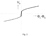
- FIG 3 shows an example of a diagram of the bridge voltage U 0 of the sensor 5 versus the difference in the mass flows of air ⁇ L and gas ⁇ G.
- the bridge voltage U 0 is formed from the difference between U Out + and U out- (see Fig. 2 ).
- the gas valve 4 is controlled in such a way that the voltage U 0 of the sensor 5 is essentially at the value 0. With different Load conditions can be determined from the resulting voltage difference, the load on the gas heater.
- control device is integrated in known gas heating devices, the load of which is controlled via the fan speed and the corresponding amount of gas supplied.
Landscapes
- Engineering & Computer Science (AREA)
- Chemical & Material Sciences (AREA)
- Combustion & Propulsion (AREA)
- Mechanical Engineering (AREA)
- General Engineering & Computer Science (AREA)
- Regulation And Control Of Combustion (AREA)
- Measuring Volume Flow (AREA)
Claims (12)
- Dispositif de régulation pour brûleur de gaz pour l'adaptation d'un mélange gaz-air formé d'un flux de gaz (G) et d'un flux d'air (L), amené au brûleur de gaz, avec une soupape de gaz (4), une conduite d'air (2), une conduite de gaz (3), qui débouche dans la conduite d'air (2), une section de pontage (6) qui est agencée entre la conduite d'air (2) et la conduite de gaz (3), dans lequel la soupape de gaz (4) est agencée dans la conduite de gaz (3), une unité de commande électronique pour la commande d'une position d'ouverture de la soupape de gaz (4) et un capteur (5), qui est relié à la commande et lui fournit des signaux, dans lequel le capteur (5) est agencé dans la section de pontage (6) entre la conduite d'air (2) et la conduite de gaz (3) et est en liaison active directe d'un côté avec le flux d'air et d'un autre côté avec le flux de gaz, dans lequel la section de pontage (6) est fermée en écoulement de sorte que le flux de gaz et le flux d'air sont séparés dans la section de pontage (6), caractérisé en ce que la section de pontage (6) est fermée par une paroi de boîtier (7), à l'intérieur de laquelle le capteur (5) est agencé par section, et le capteur (5) présente une première résistance dépendant de la température (RL), une deuxième résistance dépendant de la température (RG) et un moyen de chauffage (RH) agissant aussi bien sur la première que sur la deuxième résistance dépendant de la température (RL, RG), dans lequel la première résistance dépendant de la température (RL) est agencée dans l'écoulement d'air, la deuxième résistance dépendant de la température (RG) est agencée dans l'écoulement de gaz et le moyen de chauffage (RH) est agencé en dehors de l'écoulement d'air et de l'écoulement de gaz.
- Dispositif de régulation pour brûleur de gaz selon la revendication 1, caractérisé en ce que la paroi de boîtier (7) et/ou le capteur (5) forme/nt une liaison de conduction de chaleur de matière solide entre la conduite de gaz (2) et la conduite d'air (3).
- Dispositif de régulation pour brûleur de gaz selon l'une quelconque des revendications précédentes, caractérisé en ce que la section de pontage (6) présente un canal de dérivation de gaz (9) vers la conduite de gaz (3), dans lequel passe un flux de gaz de dérivation, et un canal de dérivation d'air (8) vers la conduite d'air (2), dans lequel passe un flux d'air de dérivation, et le capteur (5) est en liaison active directe aussi bien avec le flux de gaz de dérivation qu'avec le flux d'air de dérivation.
- Dispositif de régulation pour brûleur de gaz selon les revendications précédentes 1 et 3, caractérisé en ce que la première résistance dépendant de la température (RL) est agencée dans le flux d'air de dérivation et la deuxième résistance dépendant de la température (RG) est agencée dans le flux de gaz de dérivation.
- Dispositif de régulation pour brûleur de gaz selon au moins l'une quelconque des revendications précédentes 3-4, caractérisé en ce que respectivement au moins un écran (10, 11) est prévu dans la conduite de gaz (3) et la conduite d'air (2), et le canal de dérivation de gaz (9) et le canal de dérivation d'air (8) forment respectivement une dérivation autour de l'écran respectif (10, 11).
- Dispositif de régulation pour brûleur de gaz selon au moins l'une quelconque des revendications précédentes, caractérisé en ce qu'une section transversale d'écoulement du canal de dérivation de gaz (9) est plus petite qu'une section transversale d'écoulement du canal de dérivation d'air (8).
- Dispositif de régulation pour brûleur de gaz selon au moins l'une quelconque des revendications précédentes, caractérisé en ce que la conduite de gaz (3) et la conduite d'air (2) et/ou le canal de dérivation de gaz (9) et le canal de dérivation d'air (8) s'étendent parallèlement au moins dans la zone du capteur (5).
- Dispositif de régulation pour brûleur de gaz selon au moins l'une quelconque des revendications précédentes, caractérisé en ce que le capteur (5) est formé par une carte de circuit imprimé, avec laquelle la section de pontage (6) peut être fermée en écoulement.
- Dispositif de régulation pour brûleur de gaz selon la revendication précédente, caractérisé en ce que le moyen de chauffage est agencé à l'intérieur de la carte de circuit imprimé et les première et deuxième résistances dépendant de la température, qui sont reliées thermiquement au moyen de chauffage, sont agencées sur deux côtés extérieurs opposés de la carte de circuit imprimé.
- Procédé de fonctionnement d'un appareil de chauffage au gaz pour un brûleur de gaz avec un dispositif de régulation (1) selon au moins l'une quelconque des revendications précédentes, caractérisé en ce que l'unité de commande commande une position d'ouverture de la soupape de gaz (4) en fonction d'un signal fourni par le capteur (5).
- Procédé de fonctionnement d'un appareil de chauffage au gaz selon la revendication précédente, caractérisé en ce qu'une énergie électrique amenée au moyen de chauffage est détectée et utilisée en tant que mesure et grandeur de régulation pour la sollicitation de l'appareil de chauffage au gaz.
- Procédé de fonctionnement d'un appareil de chauffage au gaz selon la revendication précédente, caractérisé en ce que la sollicitation de l'appareil de chauffage au gaz est utilisée en tant que valeur de réglage pour une régulation adaptative au gaz de l'appareil de chauffage au gaz.
Applications Claiming Priority (2)
| Application Number | Priority Date | Filing Date | Title |
|---|---|---|---|
| DE102015117406.5A DE102015117406A1 (de) | 2015-10-13 | 2015-10-13 | Regeleinrichtung für Gasbrenner |
| PCT/EP2016/073868 WO2017063937A1 (fr) | 2015-10-13 | 2016-10-06 | Dispositif de réglage de brûleurs à gaz |
Publications (2)
| Publication Number | Publication Date |
|---|---|
| EP3325882A1 EP3325882A1 (fr) | 2018-05-30 |
| EP3325882B1 true EP3325882B1 (fr) | 2020-02-19 |
Family
ID=57113337
Family Applications (1)
| Application Number | Title | Priority Date | Filing Date |
|---|---|---|---|
| EP16778347.1A Active EP3325882B1 (fr) | 2015-10-13 | 2016-10-06 | Dispositif de régulation pour un brûleur de gaz |
Country Status (4)
| Country | Link |
|---|---|
| EP (1) | EP3325882B1 (fr) |
| CN (1) | CN208832503U (fr) |
| DE (1) | DE102015117406A1 (fr) |
| WO (1) | WO2017063937A1 (fr) |
Families Citing this family (4)
| Publication number | Priority date | Publication date | Assignee | Title |
|---|---|---|---|---|
| DE102018119457A1 (de) * | 2018-08-09 | 2020-02-13 | Ebm-Papst Landshut Gmbh | Verfahren zur Regelung eines Mischungsverhältnisses von Brenngas und Luft für ein Heizgerät |
| CN109140494B (zh) * | 2018-09-06 | 2020-01-31 | 佛山市顺德区美的洗涤电器制造有限公司 | 用于确定燃气灶的燃烧器参数的方法、装置及存储介质 |
| DE102020132503A1 (de) | 2020-12-07 | 2022-06-09 | Ebm-Papst Landshut Gmbh | Verfahren für Heizgeräte zur Anpassung eines Luft-Brennstoff-Gemisches |
| CN113566195A (zh) * | 2021-07-28 | 2021-10-29 | 深圳市联兴泰软件技术有限公司 | 一种便于负载点参数输入的燃烧机及其参数输入方法 |
Family Cites Families (7)
| Publication number | Priority date | Publication date | Assignee | Title |
|---|---|---|---|---|
| EP0644377B1 (fr) * | 1993-09-16 | 1996-10-23 | Honeywell B.V. | Dispositif de commande pour brûleur à gaz |
| DE102005034758B3 (de) | 2005-07-21 | 2006-08-10 | Honeywell Technologies S.A.R.L. | Verfahren zum Betreiben eines Gasbrenners |
| DE102007002847B4 (de) * | 2007-01-15 | 2008-10-16 | Honeywell Technologies Sarl | Verfahren zum Regeln eines Gasbrenners |
| EP2090827A3 (fr) | 2008-02-18 | 2017-09-27 | Honeywell Technologies Sarl | Dispositif de réglage pour brûleur à gaz |
| AT510002B1 (de) * | 2010-12-20 | 2012-01-15 | Vaillant Group Austria Gmbh | Verfahren zur regelung eines gas-/luftgemisches |
| ITPD20120030A1 (it) * | 2012-02-09 | 2013-08-10 | Sit La Precisa S P A Con Socio Uni Co | Metodo per il controllo di un bruciatore di una caldaia e sistema di controllo operante in accordo con tale metodo |
| US9234661B2 (en) * | 2012-09-15 | 2016-01-12 | Honeywell International Inc. | Burner control system |
-
2015
- 2015-10-13 DE DE102015117406.5A patent/DE102015117406A1/de not_active Withdrawn
-
2016
- 2016-10-06 WO PCT/EP2016/073868 patent/WO2017063937A1/fr not_active Ceased
- 2016-10-06 CN CN201690001248.2U patent/CN208832503U/zh not_active Expired - Fee Related
- 2016-10-06 EP EP16778347.1A patent/EP3325882B1/fr active Active
Non-Patent Citations (1)
| Title |
|---|
| None * |
Also Published As
| Publication number | Publication date |
|---|---|
| DE102015117406A1 (de) | 2017-04-13 |
| EP3325882A1 (fr) | 2018-05-30 |
| WO2017063937A1 (fr) | 2017-04-20 |
| CN208832503U (zh) | 2019-05-07 |
Similar Documents
| Publication | Publication Date | Title |
|---|---|---|
| EP2874039B1 (fr) | Procédé de commande pour un système de transmission de chaleur et système de transmission de chaleur de ce type | |
| EP3325882B1 (fr) | Dispositif de régulation pour un brûleur de gaz | |
| EP2960587A1 (fr) | Procédé de limitation du débit d'alimentation dans un système de transmission de chaleur | |
| EP2191205B1 (fr) | Four de cuisson à ouverture de sortie d'air | |
| EP0013298A2 (fr) | Régulateur de conditionnement d'air pour l'intérieur des véhicules, notamment des voitures | |
| EP3199876B1 (fr) | Procédé et dispositif destinés à influencer un réglage de chauffage | |
| DE3639172C2 (fr) | ||
| DE4109841C2 (de) | Regelvorrichtung für Gasbrenner mit einem Gebläse zum Zuführen von Verbrennungsluft | |
| DE2308578B2 (de) | Zenlralheizungs- und -kühlanlage | |
| EP1630361A1 (fr) | Dispositif et procédé de refroidissement d'un boîtier de turbine à gaz ou d'une chambre de combustion | |
| EP3434905B1 (fr) | Pompe à vide et procédé destiné au fonctionnement d'une pompe à vide | |
| EP1926942A1 (fr) | Echangeur thermique et procede pour reguler un echangeur thermique | |
| EP3734159A1 (fr) | Procédé de vérification d'un capteur de mélange gazeux dans un appareil chauffant fonctionnant au gaz combustible | |
| DE10348324B3 (de) | Verfahren zur Modulation der Heizleistung eines Brenners und Mischeinrichtung für einen Brenner | |
| EP0239842B1 (fr) | Procédé de réglage de la température intérieure d'un habitacle, notamment d'un véhicule automobile | |
| DE4334625A1 (de) | Verfahren zum Konstanthalten der Leistung eines Wassererwärmers | |
| DE102021119632B4 (de) | Kühlanordnung mit Differenztemperaturthermostat für ein Kraftfahrzeug, Kraftfahrzeug und Differenztemperaturthermostat | |
| DE102015113340A1 (de) | Heizungsanlage und Verfahren zum Betreiben einer Heizungsanlage | |
| EP1686329A2 (fr) | Appareil pour chauffer de l'eau | |
| DE10056064B4 (de) | Verfahren zum Regeln eines Gasbrenners | |
| DE102016107116A1 (de) | Vorrichtung und Verfahren zur Einstellung der Temperatur in einem Raum, insbesondere in einem Fahrzeug-Innenraum | |
| EP3928009B1 (fr) | Clapet de mélange pour une robinetterie sanitaire et procédé de commande d'un clapet de mélange | |
| EP2365271B1 (fr) | Evaporateur pouvant être alimenté par air, pompe à air-eau-chaleur ainsi que procédé de fabrication ou de réglage d'un évaporateur pouvant être alimenté par air ou d'une pompe à air-eau-chaleur | |
| DE19908885A1 (de) | Verfahren zum Betrieb eines mit Brenngasen wechselnder Zusammensetzungen versorgten Energieumsetzers | |
| EP4619714A1 (fr) | Système et capteur de débit pour mesure de débit d'un milieu de mesure fluide |
Legal Events
| Date | Code | Title | Description |
|---|---|---|---|
| STAA | Information on the status of an ep patent application or granted ep patent |
Free format text: STATUS: THE INTERNATIONAL PUBLICATION HAS BEEN MADE |
|
| PUAI | Public reference made under article 153(3) epc to a published international application that has entered the european phase |
Free format text: ORIGINAL CODE: 0009012 |
|
| STAA | Information on the status of an ep patent application or granted ep patent |
Free format text: STATUS: REQUEST FOR EXAMINATION WAS MADE |
|
| 17P | Request for examination filed |
Effective date: 20180222 |
|
| AK | Designated contracting states |
Kind code of ref document: A1 Designated state(s): AL AT BE BG CH CY CZ DE DK EE ES FI FR GB GR HR HU IE IS IT LI LT LU LV MC MK MT NL NO PL PT RO RS SE SI SK SM TR |
|
| AX | Request for extension of the european patent |
Extension state: BA ME |
|
| DAV | Request for validation of the european patent (deleted) | ||
| DAX | Request for extension of the european patent (deleted) | ||
| GRAP | Despatch of communication of intention to grant a patent |
Free format text: ORIGINAL CODE: EPIDOSNIGR1 |
|
| STAA | Information on the status of an ep patent application or granted ep patent |
Free format text: STATUS: GRANT OF PATENT IS INTENDED |
|
| INTG | Intention to grant announced |
Effective date: 20191031 |
|
| GRAS | Grant fee paid |
Free format text: ORIGINAL CODE: EPIDOSNIGR3 |
|
| GRAA | (expected) grant |
Free format text: ORIGINAL CODE: 0009210 |
|
| STAA | Information on the status of an ep patent application or granted ep patent |
Free format text: STATUS: THE PATENT HAS BEEN GRANTED |
|
| AK | Designated contracting states |
Kind code of ref document: B1 Designated state(s): AL AT BE BG CH CY CZ DE DK EE ES FI FR GB GR HR HU IE IS IT LI LT LU LV MC MK MT NL NO PL PT RO RS SE SI SK SM TR |
|
| REG | Reference to a national code |
Ref country code: CH Ref legal event code: EP |
|
| REG | Reference to a national code |
Ref country code: DE Ref legal event code: R096 Ref document number: 502016008832 Country of ref document: DE |
|
| REG | Reference to a national code |
Ref country code: AT Ref legal event code: REF Ref document number: 1235398 Country of ref document: AT Kind code of ref document: T Effective date: 20200315 |
|
| REG | Reference to a national code |
Ref country code: IE Ref legal event code: FG4D Free format text: LANGUAGE OF EP DOCUMENT: GERMAN |
|
| REG | Reference to a national code |
Ref country code: NL Ref legal event code: FP |
|
| PG25 | Lapsed in a contracting state [announced via postgrant information from national office to epo] |
Ref country code: NO Free format text: LAPSE BECAUSE OF FAILURE TO SUBMIT A TRANSLATION OF THE DESCRIPTION OR TO PAY THE FEE WITHIN THE PRESCRIBED TIME-LIMIT Effective date: 20200519 Ref country code: FI Free format text: LAPSE BECAUSE OF FAILURE TO SUBMIT A TRANSLATION OF THE DESCRIPTION OR TO PAY THE FEE WITHIN THE PRESCRIBED TIME-LIMIT Effective date: 20200219 Ref country code: RS Free format text: LAPSE BECAUSE OF FAILURE TO SUBMIT A TRANSLATION OF THE DESCRIPTION OR TO PAY THE FEE WITHIN THE PRESCRIBED TIME-LIMIT Effective date: 20200219 |
|
| REG | Reference to a national code |
Ref country code: LT Ref legal event code: MG4D |
|
| PG25 | Lapsed in a contracting state [announced via postgrant information from national office to epo] |
Ref country code: HR Free format text: LAPSE BECAUSE OF FAILURE TO SUBMIT A TRANSLATION OF THE DESCRIPTION OR TO PAY THE FEE WITHIN THE PRESCRIBED TIME-LIMIT Effective date: 20200219 Ref country code: SE Free format text: LAPSE BECAUSE OF FAILURE TO SUBMIT A TRANSLATION OF THE DESCRIPTION OR TO PAY THE FEE WITHIN THE PRESCRIBED TIME-LIMIT Effective date: 20200219 Ref country code: LV Free format text: LAPSE BECAUSE OF FAILURE TO SUBMIT A TRANSLATION OF THE DESCRIPTION OR TO PAY THE FEE WITHIN THE PRESCRIBED TIME-LIMIT Effective date: 20200219 Ref country code: GR Free format text: LAPSE BECAUSE OF FAILURE TO SUBMIT A TRANSLATION OF THE DESCRIPTION OR TO PAY THE FEE WITHIN THE PRESCRIBED TIME-LIMIT Effective date: 20200520 Ref country code: BG Free format text: LAPSE BECAUSE OF FAILURE TO SUBMIT A TRANSLATION OF THE DESCRIPTION OR TO PAY THE FEE WITHIN THE PRESCRIBED TIME-LIMIT Effective date: 20200519 Ref country code: IS Free format text: LAPSE BECAUSE OF FAILURE TO SUBMIT A TRANSLATION OF THE DESCRIPTION OR TO PAY THE FEE WITHIN THE PRESCRIBED TIME-LIMIT Effective date: 20200619 |
|
| PG25 | Lapsed in a contracting state [announced via postgrant information from national office to epo] |
Ref country code: RO Free format text: LAPSE BECAUSE OF FAILURE TO SUBMIT A TRANSLATION OF THE DESCRIPTION OR TO PAY THE FEE WITHIN THE PRESCRIBED TIME-LIMIT Effective date: 20200219 Ref country code: CZ Free format text: LAPSE BECAUSE OF FAILURE TO SUBMIT A TRANSLATION OF THE DESCRIPTION OR TO PAY THE FEE WITHIN THE PRESCRIBED TIME-LIMIT Effective date: 20200219 Ref country code: PT Free format text: LAPSE BECAUSE OF FAILURE TO SUBMIT A TRANSLATION OF THE DESCRIPTION OR TO PAY THE FEE WITHIN THE PRESCRIBED TIME-LIMIT Effective date: 20200712 Ref country code: SK Free format text: LAPSE BECAUSE OF FAILURE TO SUBMIT A TRANSLATION OF THE DESCRIPTION OR TO PAY THE FEE WITHIN THE PRESCRIBED TIME-LIMIT Effective date: 20200219 Ref country code: LT Free format text: LAPSE BECAUSE OF FAILURE TO SUBMIT A TRANSLATION OF THE DESCRIPTION OR TO PAY THE FEE WITHIN THE PRESCRIBED TIME-LIMIT Effective date: 20200219 Ref country code: ES Free format text: LAPSE BECAUSE OF FAILURE TO SUBMIT A TRANSLATION OF THE DESCRIPTION OR TO PAY THE FEE WITHIN THE PRESCRIBED TIME-LIMIT Effective date: 20200219 Ref country code: DK Free format text: LAPSE BECAUSE OF FAILURE TO SUBMIT A TRANSLATION OF THE DESCRIPTION OR TO PAY THE FEE WITHIN THE PRESCRIBED TIME-LIMIT Effective date: 20200219 Ref country code: SM Free format text: LAPSE BECAUSE OF FAILURE TO SUBMIT A TRANSLATION OF THE DESCRIPTION OR TO PAY THE FEE WITHIN THE PRESCRIBED TIME-LIMIT Effective date: 20200219 Ref country code: EE Free format text: LAPSE BECAUSE OF FAILURE TO SUBMIT A TRANSLATION OF THE DESCRIPTION OR TO PAY THE FEE WITHIN THE PRESCRIBED TIME-LIMIT Effective date: 20200219 |
|
| REG | Reference to a national code |
Ref country code: DE Ref legal event code: R097 Ref document number: 502016008832 Country of ref document: DE |
|
| PLBE | No opposition filed within time limit |
Free format text: ORIGINAL CODE: 0009261 |
|
| STAA | Information on the status of an ep patent application or granted ep patent |
Free format text: STATUS: NO OPPOSITION FILED WITHIN TIME LIMIT |
|
| 26N | No opposition filed |
Effective date: 20201120 |
|
| PG25 | Lapsed in a contracting state [announced via postgrant information from national office to epo] |
Ref country code: PL Free format text: LAPSE BECAUSE OF FAILURE TO SUBMIT A TRANSLATION OF THE DESCRIPTION OR TO PAY THE FEE WITHIN THE PRESCRIBED TIME-LIMIT Effective date: 20200219 Ref country code: SI Free format text: LAPSE BECAUSE OF FAILURE TO SUBMIT A TRANSLATION OF THE DESCRIPTION OR TO PAY THE FEE WITHIN THE PRESCRIBED TIME-LIMIT Effective date: 20200219 |
|
| REG | Reference to a national code |
Ref country code: CH Ref legal event code: PL |
|
| PG25 | Lapsed in a contracting state [announced via postgrant information from national office to epo] |
Ref country code: MC Free format text: LAPSE BECAUSE OF FAILURE TO SUBMIT A TRANSLATION OF THE DESCRIPTION OR TO PAY THE FEE WITHIN THE PRESCRIBED TIME-LIMIT Effective date: 20200219 Ref country code: LU Free format text: LAPSE BECAUSE OF NON-PAYMENT OF DUE FEES Effective date: 20201006 |
|
| REG | Reference to a national code |
Ref country code: BE Ref legal event code: MM Effective date: 20201031 |
|
| PG25 | Lapsed in a contracting state [announced via postgrant information from national office to epo] |
Ref country code: LI Free format text: LAPSE BECAUSE OF NON-PAYMENT OF DUE FEES Effective date: 20201031 Ref country code: CH Free format text: LAPSE BECAUSE OF NON-PAYMENT OF DUE FEES Effective date: 20201031 Ref country code: BE Free format text: LAPSE BECAUSE OF NON-PAYMENT OF DUE FEES Effective date: 20201031 |
|
| PG25 | Lapsed in a contracting state [announced via postgrant information from national office to epo] |
Ref country code: IE Free format text: LAPSE BECAUSE OF NON-PAYMENT OF DUE FEES Effective date: 20201006 |
|
| PG25 | Lapsed in a contracting state [announced via postgrant information from national office to epo] |
Ref country code: MT Free format text: LAPSE BECAUSE OF FAILURE TO SUBMIT A TRANSLATION OF THE DESCRIPTION OR TO PAY THE FEE WITHIN THE PRESCRIBED TIME-LIMIT Effective date: 20200219 Ref country code: CY Free format text: LAPSE BECAUSE OF FAILURE TO SUBMIT A TRANSLATION OF THE DESCRIPTION OR TO PAY THE FEE WITHIN THE PRESCRIBED TIME-LIMIT Effective date: 20200219 |
|
| PG25 | Lapsed in a contracting state [announced via postgrant information from national office to epo] |
Ref country code: MK Free format text: LAPSE BECAUSE OF FAILURE TO SUBMIT A TRANSLATION OF THE DESCRIPTION OR TO PAY THE FEE WITHIN THE PRESCRIBED TIME-LIMIT Effective date: 20200219 Ref country code: AL Free format text: LAPSE BECAUSE OF FAILURE TO SUBMIT A TRANSLATION OF THE DESCRIPTION OR TO PAY THE FEE WITHIN THE PRESCRIBED TIME-LIMIT Effective date: 20200219 |
|
| REG | Reference to a national code |
Ref country code: AT Ref legal event code: MM01 Ref document number: 1235398 Country of ref document: AT Kind code of ref document: T Effective date: 20211006 |
|
| PG25 | Lapsed in a contracting state [announced via postgrant information from national office to epo] |
Ref country code: AT Free format text: LAPSE BECAUSE OF NON-PAYMENT OF DUE FEES Effective date: 20211006 |
|
| P01 | Opt-out of the competence of the unified patent court (upc) registered |
Effective date: 20230521 |
|
| PGFP | Annual fee paid to national office [announced via postgrant information from national office to epo] |
Ref country code: TR Payment date: 20230929 Year of fee payment: 8 |
|
| PGFP | Annual fee paid to national office [announced via postgrant information from national office to epo] |
Ref country code: NL Payment date: 20231023 Year of fee payment: 8 |
|
| PGFP | Annual fee paid to national office [announced via postgrant information from national office to epo] |
Ref country code: GB Payment date: 20231025 Year of fee payment: 8 |
|
| PGFP | Annual fee paid to national office [announced via postgrant information from national office to epo] |
Ref country code: IT Payment date: 20231031 Year of fee payment: 8 Ref country code: FR Payment date: 20231023 Year of fee payment: 8 Ref country code: DE Payment date: 20231018 Year of fee payment: 8 |
|
| REG | Reference to a national code |
Ref country code: DE Ref legal event code: R119 Ref document number: 502016008832 Country of ref document: DE |
|
| REG | Reference to a national code |
Ref country code: NL Ref legal event code: MM Effective date: 20241101 |
|
| GBPC | Gb: european patent ceased through non-payment of renewal fee |
Effective date: 20241006 |
|
| PG25 | Lapsed in a contracting state [announced via postgrant information from national office to epo] |
Ref country code: DE Free format text: LAPSE BECAUSE OF NON-PAYMENT OF DUE FEES Effective date: 20250501 |
|
| PG25 | Lapsed in a contracting state [announced via postgrant information from national office to epo] |
Ref country code: GB Free format text: LAPSE BECAUSE OF NON-PAYMENT OF DUE FEES Effective date: 20241006 |
|
| PG25 | Lapsed in a contracting state [announced via postgrant information from national office to epo] |
Ref country code: NL Free format text: LAPSE BECAUSE OF NON-PAYMENT OF DUE FEES Effective date: 20241101 |
|
| PG25 | Lapsed in a contracting state [announced via postgrant information from national office to epo] |
Ref country code: FR Free format text: LAPSE BECAUSE OF NON-PAYMENT OF DUE FEES Effective date: 20241031 |
|
| PG25 | Lapsed in a contracting state [announced via postgrant information from national office to epo] |
Ref country code: IT Free format text: LAPSE BECAUSE OF NON-PAYMENT OF DUE FEES Effective date: 20241006 |