EP3326423B1 - Protocoles relais de la couche 2 et procédé relais de mobilité - Google Patents
Protocoles relais de la couche 2 et procédé relais de mobilité Download PDFInfo
- Publication number
- EP3326423B1 EP3326423B1 EP15826208.9A EP15826208A EP3326423B1 EP 3326423 B1 EP3326423 B1 EP 3326423B1 EP 15826208 A EP15826208 A EP 15826208A EP 3326423 B1 EP3326423 B1 EP 3326423B1
- Authority
- EP
- European Patent Office
- Prior art keywords
- relay
- remote
- data unit
- service data
- enb
- Prior art date
- Legal status (The legal status is an assumption and is not a legal conclusion. Google has not performed a legal analysis and makes no representation as to the accuracy of the status listed.)
- Active
Links
Images






Classifications
-
- H—ELECTRICITY
- H04—ELECTRIC COMMUNICATION TECHNIQUE
- H04W—WIRELESS COMMUNICATION NETWORKS
- H04W76/00—Connection management
- H04W76/10—Connection setup
-
- H—ELECTRICITY
- H04—ELECTRIC COMMUNICATION TECHNIQUE
- H04W—WIRELESS COMMUNICATION NETWORKS
- H04W88/00—Devices specially adapted for wireless communication networks, e.g. terminals, base stations or access point devices
- H04W88/02—Terminal devices
- H04W88/04—Terminal devices adapted for relaying to or from another terminal or user
Definitions
- Embodiments described herein generally relate to the field of wireless communications and, more particularly, to methods and apparatus for facilitating relaying in a wireless communication system.
- 3GPP TS23.303 V13.0.0 provides further details about proximity services.
- the phrase "in one embodiment” is used repeatedly. The phrase generally does not refer to the same embodiment; however, it may.
- the terms "comprising,” “having,” and “including” are synonymous, unless the context dictates otherwise.
- the phrase “A/B” means “A or B”.
- the phrase “A and/or B” means “(A), (B), or (A and B)”.
- the phrase “at least one of A, B and C” means "(A), (B), (C), (A and B), (A and C), (B and C) or (A, B and C)".
- the phrase “(A) B” means "(B) or (A B)", that is, A is optional.
- module may refer to, be part of, or include an Application Specific Integrated Circuit (ASIC), an electronic circuit, a processor (shared, dedicated, or group) and/or memory (shared, dedicated, or group) that execute one or more software or firmware instructions and/or programs, a combinational logic circuit, and/or other suitable components that provide the described functionality.
- ASIC Application Specific Integrated Circuit
- processor shared, dedicated, or group
- memory shared, dedicated, or group
- Radio systems specifically included within the scope of the present invention include, but are not limited to, network interface cards (NICs), network adaptors, fixed or mobile client devices, relays, base stations, femtocells, gateways, bridges, hubs, routers, access points, or other network devices.
- NICs network interface cards
- network adaptors fixed or mobile client devices
- relays base stations
- femtocells gateways
- bridges hubs
- routers access points, or other network devices.
- radio systems within the scope of the invention may be implemented in cellular radiotelephone systems, satellite systems, two-way radio systems as well as computing devices including such radio systems including personal computers (PCs), tablets and related peripherals, personal digital assistants (PDAs), personal computing accessories, hand-held communication devices and all systems which may be related in nature and to which the principles of the inventive embodiments could be suitably applied.
- PCs personal computers
- PDAs personal digital assistants
- hand-held communication devices and all systems which may be related in nature and to which the principles of the inventive embodiments could be suitably applied.
- FIG. 1 schematically illustrates a wireless communication network 100 in accordance with various embodiments.
- Wireless communication network 100 may be an access network of a 3rd Generation Partnership Project (3GPP) long-term evolution (LTE) or long-term evolution- advanced (LTE-A) network such as an evolved universal mobile telecommunication system (UMTS) terrestrial radio access network (E-UTRAN).
- 3GPP 3rd Generation Partnership Project
- LTE long-term evolution
- LTE-A long-term evolution- advanced
- E-UTRAN evolved universal mobile telecommunication system
- E-UTRAN evolved universal mobile telecommunication system
- the network 100 includes a base station, e.g., evolved node base station (eNB) 102, configured to wirelessly communicate with one or more mobile device(s) or terminal(s), e.g., first and second user equipment (UE) 104, 106.
- eNB evolved node base station
- the eNB 102 may be a fixed station (e.g., a fixed node) or a mobile station/node.
- the first UE 104 is able to provide relaying functionality to forward data received from the eNB 102 to the second, remote, UE 106.
- Relay UE 108 communicates with the eNB 102 via a traditional Uu air interface 108, and with remote UE 106 via a sidelink interface 110.
- Remote UE 106 may also be able to communicate directly with the eNB 102 via Uu interface 108'.
- FIG. 2 is a block diagram showing the use of sidelink relaying for the public safety use case.
- the Remote UE 106 is generally considered out-of-coverage of the network 100, and in particular the eNB 102, and is utilizing relay support to access the network 100.
- the Remote UE 106 accesses the network via the relay UE 104 using an interface called the 'PC5' interface and the Proximity Services (ProSe) UE-to-Network Relay, which is shortly referred to as 'Relay UE' 104 throughout this document, connects to the network 100 using the legacy LTE Uu link.
- the relay UE 104 is assumed to be in-coverage all the time.
- service continuity is dependent on the application level to be maintained, especially when IP address changes during relay change or direct to relay path change. This may cause complications when providing certain services via a relay link.
- the introduced LTE ProSe framework may be further enhanced to support General use cases that may be of interest to operators with end users and may allow substantial improvements to network performance and user experience to be achieved.
- the ProSe framework design has been primarily focused on Public Safety services, while more General use cases had been considered as mainly out of scope.
- the Public Safety services determined the main design vectors in LTE Rel.12 ProSe framework targeting long-range broadcast communication which is robust to interference and has a relatively low peak data rate.
- further enhancements to the device-to-device sidelink air-interface introduced as part of the ProSe framework may be also used for network optimization and have potential to improve user experience and increase the amount of services that can be provided.
- D2D device-to-device
- One of the more general use cases to which device-to-device (D2D) operation may be targeted is traffic management/offloading and utilization of its inherent multi-connectivity properties.
- Empowering sidelink air-interface and exploiting the new dimension of connectivity may bring additional benefits to mobile broadband and MTC applications, establishing principles of underlay network operation.
- Advanced relaying capability for UEs that are in coverage with the network as described below according to some embodiments of the invention, may facilitate improvements in network efficiency, traffic switching delay reduction and other advantages.
- the relay path may be switched dynamically (between direct and indirect links) and may also be able to support different paths for uplink and downlink directions.
- this flexible switching and asymmetric relay path selection are not feasible with L3 routing, at the IP-Layer currently provided in Rel-13.
- Various embodiments of the invention may assume that the remote UE 106 to be served by a relay path is in coverage of the eNB 102, and that the remote UE 106 is in connected mode, or has been in connected mode such that the UE context is available in the eNB 102.
- SRBs signaling radio bearers
- DRBs data radio bearers
- MME and S-GW eNB and core network
- the Relay UE 104 remains in coverage of the eNB 102 for the duration of the relaying operation.
- advanced relaying is performed using a relay UE (a UE with certain relaying capabilities) via layer 2 routing.
- a relay UE a UE with certain relaying capabilities
- L3 relay UE has been agreed upon and defined.
- the relaying may be performed either right above MAC in true L2 sense or above the LTE layer RLC (Radio Link Control).
- Example embodiments are described setting out:
- Figure 3a illustrates a protocol stack at the Remote UE 106, Relay UE 104 and eNB 102 to support forwarding or relaying of traffic within the Relay UE 104 just above the MAC layer according to some embodiments of the invention.
- Figure 3a illustrates an arrangement in which the remote UE 106 communicates directly with the eNB 102 via the Uu interface 108'.
- the remote UE 106 protocol stack comprises an IP layer 302 connected to a packet data convergence protocol (PDCP) layer 304, which is connected to a radio link control (RLC) layer 306.
- Packet data units (PDUs) provided by the RLC layer 306 are then directed by a route switch 308 to one of a device to network (D2N) MAC entity 310a and a device to device (D2D) MAC entity 310b.
- D2N MAC 310a provides a connection to the eNB 102 via a Uu air interface 108', while D2D MAC connects to relay UE 104 via the sidelink, PCS, interface 110.
- Relay UE 104 is similarly provided with two MAC entities, D2D MAC 320a for communication with the remote UE 106 via the sidelink interface 110 and D2N MAC 320b for communication with the eNB 102 via the Uu interface 108.
- Figure 3a further illustrates the protocol stack of eNB 102 comprising a PDCP layer 330 that is coupled with the wider communication network via S1 bearer 322 and with RLC layer 334.
- RLC layer 334 is coupled to route switch 336 for directing PDUs to either a D2N MAC entity 340a for communication with the remote UE 106 via the Uu interface 108' or to a D2N MAC entity 340b for communication via a relay path through relay UE 104.
- Figure 3b illustrates the same arrangement as Figure 3a where the communication path between the remote UE 106 and the eNB 102 is relayed via the relay UE 104.
- MAC SDUs received on the PCS interface 110 between the Remote UE 106 and the Relay UE 104 are directly submitted as MAC SDUs on the uplink (UL) of the Uu interface 108 between the Relay UE 104 and the eNB 102.
- MAC SDUs received on the downlink (DL) of the Uu interface 108 between the eNB 102 and the Relay UE 104 are directly submitted as MAC SDUs on the PCS interface 110 between the Relay UE 104 and the Remote UE 106.
- the relaying function may include a buffer to enable the MAC SDUs to be queued until a convenient time for transmission e.g. until resource is scheduled.
- the Remote UE 106 and the eNB 102 include route switching functions 308, 336.
- the switching function 308 enables RLC PDUs (i.e. MAC SDUs) to be switched between the MAC used on the PC5 interface 110 (referred to as D2D (device to device) MAC 310a in the figure) and the MAC used on the Uu interface 108' (referred to as D2N (device to network) MAC 310b in the figure).
- the switching function 336 enables RLC PDUs (i.e. MAC SDUs) to be switched between the MAC 340a used on the Uu interface 108' for the Remote UE 106 and the MAC 340b used on the Uu interface 108 for the Relay UE 104.
- RLC PDUs i.e. MAC SDUs
- switching may be controlled by determining that the data arrives from a certain configured logical channel (and possibly if the remote UE 106 is configured for the transmission via the relay UE 104 or if the remote UE is already associated with the certain relay UE 104), the UE transmits the data through D2D MAC.
- Another example of switching may be if the UE is configured for the transmission via the relay UE 104 or if the UE 106 is already associated with the certain relay UE 104, the UE transmits the data through D2D MAC regardless from which logical channel data is arrived.
- a further example of switching may be to decide whether the data is transmitted through D2N MAC or D2D MAC entity on a packet by packet basis, determined using a packet filtering function.
- such a switching function may be located above the MAC, however embodiments of the invention are not restricted to the switching function being located above the MAC and other location may be used, e.g. the switch function may be located in an upper or lower layer.
- FIG. 3a/3b shows a single Data Radio Bearer (DRB) in the Remote UE 106 and the eNB 102.
- DRB Data Radio Bearer
- LCIDs logical channel identities
- the eNB 102 may need to be aware of the mapping between all 4 identities, but the Remote UE 106 may only need to be aware of the mapping between 1/2/3 and the Relay UE 104 may only need to be aware of the mapping between 3/4.
- the mapping information may be configured in the Remote UE 106 and Relay UE 104 from the eNB 102 using, for example, the RRC Connection Reconfiguration procedure.
- the embodiment illustrated in Figure 3a/3b shows only a single remote UE 106 but it is possible that the Relay UE 104 may be engaged in relaying traffic for multiple Remote UEs. In this case the traffic associated with the different Remote UEs may needs to be separated in the Relay UE 104 and the eNB 102. This may be achieved by ensuring that the different Remote UEs are mapped to different logical channel identities on the Uu interface 108 between eNB 102 and Relay UE 104 (i.e. identity 4 in the list above may be unique among all the Remote UEs served by the Relay UE 104 and this identity has the purpose to identify the Remote UE 106 as well as to identity one DRB of that Remote UE).
- identity 4 in the list above may be unique among all the Remote UEs served by the Relay UE 104 and this identity has the purpose to identify the Remote UE 106 as well as to identity one DRB of that Remote UE).
- the remote UE ID (e.g. C-RNT! or separate assigned L2 id to the remote UE 106 for routing purpose) of each MAC SDU may be included in MAC PDU header or MAC PDU subheader. This may then be used by the eNB 102 to map logical channel identity (2/3) to logical channel identity (4) in eNB side.
- DRBs While the discussion above refers to DRBs, it will be recognized that it may apply equally to control plane traffic (i.e. RRC and NAS signaling) could also be carried via the relay path. This may be achieved by extending the approach above to including mapping information for Signaling Radio Bearer (SRB) identities as well as DRB identities.
- SRB Signaling Radio Bearer
- FIGs 4a and 4b illustrate a protocol stack at the Remote UE 106, Relay UE 104 and eNB 102 similar to that illustrated in Figures 3a/3b but to support forwarding or relaying of traffic within the Relay UE 104 just above the RLC layer 422.
- RLC SDUs received on the PC5 interface 110 between the Remote UE 104 and the Relay UE 106 are directly submitted as RLC SDUs on the uplink (UL) of the Uu interface 108 between the Relay UE 104 and the eNB 102.
- UL uplink
- RLC SDUs received on the downlink (DL) of the Uu interface 108 between the eNB 102 and the Relay UE 104 are directly submitted as RLC SDUs on the PCS interface 110 between the Relay UE 104 and the Remote UE 102.
- the relaying function may not need to support any buffering as the RLC entity 422 below the relaying function has the ability to buffer data.
- the Remote UE 106 and eNB 102 also include route switching functions 408, 436. These functions are similar to those described for the Relay above MAC option of Figures 3a/3b . However in the embodiment of Figures 4a/4b is that the route switching 408, 436 sits above the RLC layer 406, 434 instead of above the MAC.
- FIGs 5a and 5b illustrate a protocol stack at the Remote UE 106, Relay UE 104 and eNB 102 similar to that illustrated in Figures 4a/4b to support forwarding or relaying of traffic within the Relay UE 104 above the RLC layer.
- the protocol stack between the Relay UE 104 and the eNB 102 introduces an additional protocol layer which is referred to here as the Relay Protocol (RP) 524, 538.
- the purpose of the Relay Protocol is to multiplex traffic from multiple Remote UEs and also from multiple DRBs and SRBs of each Remote UE 106 onto a single radio bearer (or possibly a limited number of different radio bearers) between the Relay UE 104 and the eNB 102.
- the Relay Protocol may also provide a header that contains a Remote UE ID and DRB or SRB ID, so that the multiplexed traffic may be de-multiplexed at the receiving end.
- FIG. 6 illustrates an example of the PDU format 600 of the Relay Protocol including a remote UE ID 602, a radio bearer ID 604, and a relay protocol SDU 606.
- the Remote UE ID 602 identifies the Remote UE 102.
- the field may identify the UE uniquely within the eNB 102 by carrying a combination of Cell Global Identity (CGI) and C-RNTI, or it may be a new type of RNTI allocated by the eNB, or it may be a Short ID that is sufficiently long to identify the Remote UE uniquely within the Remote UEs that are associated with a single Relay UE 104.
- CGI Cell Global Identity
- C-RNTI Short ID that is sufficiently long to identify the Remote UE uniquely within the Remote UEs that are associated with a single Relay UE 104.
- Short ID may be that it introduces less overhead per RP PDU.
- the Remote UE ID may be a Short ID, and an optionally present larger Remote UE ID (e.g. CGI + C-RNT! or new type of RNTI) may also be present.
- an optionally present larger Remote UE ID e.g. CGI + C-RNT! or new type of RNTI.
- the Radio Bearer ID 604 may contain a DRB ID or it may contain an EPS Bearer ID. If control plane signaling is also to be carried via the relay path then this field may also contain an SRB ID. If multiplexing data of multiple UEs is performed for the same QoS data and same radio bearer ID, radio bearer ID may be omitted.
- the Relay Protocol SDU 606 may correspond to the RLC SDU that is to be carried between eNB and Remote UE.
- RLC SDUs 606 received on the PC5 interface 110 between the Remote UE 106 and the Relay UE 104 are directly submitted as Relay Protocol SDUs 606 on the uplink (UL) of the Uu interface 108 between the Relay UE 104 and the eNB 102.
- the Relay Protocol adds the Remote UE ID 602 and SRB/DRB ID 604 into the header.
- Relay Protocol SDUs 606 received on the downlink (DL) of the Uu interface 108 between the eNB 102 and the Relay UE 104 are directly submitted as RLC SDUs 606 on the PCS interface 110 between the Relay UE 104 and the Remote UE 106.
- the relaying function may not need to support any buffering as the RLC entity may have the ability to buffer data.
- logical channel id may be used instead of radio bearer id in the above figure.
- Figure 7 illustrates a MAC subheader header format or MAC header format that may be used for a similar purpose to the relay protocol PDU format of Figure 6 .
- the illustrated MAC sub-header formats of Figure 7 are illustrated MAC sub-header formats of Figure 7 :
- Figure 8 illustrates an example MAC PDU for relaying communications from multiple remote UEs using the MAC subheader format of Figure 7 .
- the information of all subheaders for remote UEs may be included as part of MAC control information, e.g. in the above figure instead of using MAC subheader, information included in the subheader for remote UE#1, remote UE#2, remote UE#3, and remote UE#4 may be included into the new MAC control information element.
- the existing MAC subheader format may be reused with the new logical channel id, which newly to be defined to indicate this MAC control information element.
- RP 524 is located in the above RLC 422 in Figures 5a/5b and the corresponding description, this disclosure does not have any restriction for the RP location, e.g. according to some embodiments the RP function may be performed in above the RLC or below RLC or in the RLC.
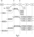
- Figure 9 illustrates how the traffic associated with multiple Remote UEs may be multiplexed onto a single (or limited number of radio bearers) on the Uu interface 108 between the Relay UE 104 and the eNB 102.
- a small number of radio bearers on the Uu interface 108 may be useful to support some QoS differentiation.
- three radio bearers could be configured on the Uu interface 108 with one carrying SRB signaling for all the Remote UEs, one carrying GBR (Guaranteed Bit Rate) QoS traffic for all the Remote UEs, and one carrying the non-GBR QoS traffic for all the Remote UEs.
- GBR Guard Bit Rate
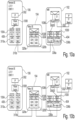
- Figures 10a/10b illustrate a further protocol stack similar to that illustrated in Figures 3a/3b and Figures 4a/4b according to some embodiments of the invention.
- the Remote UE, Relay UE and eNB support forwarding or relaying of traffic within the Relay UE 104 just above the PDCP layer 1026.
- PDCP SDUs received on the PCS interface 110 between the Remote UE 106 and the Relay UE 104 are directly submitted as PDCP SDUs on the uplink (UL) of the Uu interface 108 between the Relay UE 104 and the eNB 102.
- UL uplink
- PDCP SDUs received on the downlink (DL) of the Uu interface 108 between the eNB 102 and the Relay UE 104 are directly submitted as PDCP SDUs on the PCS interface 110 between the Relay UE 104 and the Remote UE 106.
- the relaying function may not need to support any buffering as the RLC entity below the relaying function has the ability to buffer data.
- the Remote UE 106 and eNB 102 also include route switching functions 1008, 1036. These functions are similar to those described for the Relay above MAC option of Figures 3a/3b . The only difference is that the route switching sits above PDCP instead of above MAC.
- a relay protocol may be introduced above PDCP layer in the relay UE 106 and eNB 102.
- the relay protocol may facilitate multiplexing of multiple UEs/radio bearers over Uu interface 108 between the relay UE 104 and the eNB 102.
- the remote UE 106 may be able to select a path to communicate with an eNB 102 from a plurality of available paths including a direct path between the remote UE 106 and the eNB 102 and at least one relay path via a relay UE 104.
- the remote UE 106 may then inform the eNB of the selected path, either via the direct path or the relay path.
- Figure 11 illustrates an example message sequence chart for mobility related signaling between a remote UE 106, a first relay UE 104a, a second relay UE 104b and an eNB 102 for remote UE directed mobility.
- Figure 11 illustrates the signaling involved as the Remote UE 106 initially communicates via a direct path with the eNB 102, then changes to an indirect path via Relay UE 1 104a, then to an indirect path via Relay UE 2 104b, and finally returns to using the direct path with the eNB 102.
- the elements of the sequence are described below:
- the sequence shown in Figure 11 is an example implementation and variations to the sequence are possible. For example, some variations are described below:
- the approach illustrated in Figure 11 assumes that the network to Remote UE traffic path and the Remote UE to network traffic path (i.e. downlink and uplink paths) are the same. However, according to some embodiments the approach may be extended to support different traffic paths in the uplink and downlink directions.
- the network to Remote UE traffic may be routed via a relay but the Remote UE to network traffic may be carried on the direct Uu interface path.
- the messages sent at elements 4 and 5, 11 and 12, and 17 may be extended to indicate whether it applied to network to Remote UE direction of traffic only, Remote UE to network direction of traffic only, or both directions of traffic.
- the approach illustrated in Figure 11 assumes that only a single Relay UE 104 is used at any time. However, according to some embodiments the approach may be extended to support more than one Relay UE at the same time.
- the UE may establish a connection with more than one Relay UE and then decide on a more dynamic basis (e.g. every few 100ms or in the most extreme case every packet) the path on which to route the Remote UE to network direction of traffic.
- the eNB it may decide on a dynamic basis the path on which to route the network to Remote UE direction of traffic.
- the possible paths would include the direct Uu interface path as well as indirect paths via the one or more Relay UEs.
- the possible Relay UEs that may be used for routing traffic may be referred to as a 'Relay UE candidate set'.
- the approach illustrated in Figure 11 used explicit control plane signaling between the Relay UE and the eNB to inform the eNB about a new traffic path (i.e. shown in the figure as the Relay Path Switch messages).
- explicit control plane signaling is used at element 17 when the UE returns to using the direct Uu interface path.
- this explicit signaling may be avoided by the eNB interpreting a first packet received from the remote UE via a new path as an implicit path switch message. If a change in both remote UE to network and network to remote UE is desired (as per initial configuration exchange), then, the first packet from remote UE via the new path may be used as a trigger.
- the remote UE may send a notification to the relay UE over the PCS interface that it wishes to switch the specific traffic identified by a given ID and the relay UE may indicate to the eNB over the Uu interface for path switching.
- Some embodiments of the invention may handle RLC AM bearer after selection of new relay UE (e.g. relay UE#2) as follows. This may be applicable to RLC AM bearer after switching between the direct path (transmission/reception directly between the remote UE and the eNB) and the relay path (transmission/reception via the relay UE):
- the eNB may transmit PDCP SDUs based on reporting by the remote UE after selection of new relay UE (e.g. relay UE#2).
- the reporting by the remote UE may indicate PDCP SDUs which were transmitted successfully in the old relay UE (e.g. relay UE#1) with the corresponding PDCP SDU SN and PDCP SDUs which has not been transmitted successfully in the old relay UE with the corresponding PDCP SDU SN.
- the remote UE may re-transmit to the new relay UE all UL PDCP SDUs starting from the first PDCP SDU following the last consecutively confirmed PDCP SDU, i.e. the oldest PDCP SDU that has not been acknowledged at RLC in the old relay UE.
- the approach illustrated in Figure 11 used explicit control plane signaling between the Relay UE and the eNB to inform the eNB about a new traffic path (i.e. shown in the figure as the Relay Path Switch messages).
- explicit control plane signaling is used at element 17 when the UE returns to using the direct Uu interface path.
- this explicit signaling could be avoided if the eNB interprets a first packet received from the remote UE via a new path as an implicit path switch message. If a change in both remote UE to network and network to remote UE is desired (as per initial configuration exchange), then, the first packet from remote UE via the new path may be used as a trigger.
- the remote UE associated with the new relay UE there may be signaling either by the remote UE or the eNB during or after path switch to let the old relay UE know that, so the old relay UE releases the corresponding remote UE context and forward the data PDU to the new relay UE if needed.
- the relay UE maintains a kind of inactivity timer to release the remote UE context since the signaling by the remote UE is not always guaranteed (e.g. the radio link failure case).
- the eNB 102 may be able to select a traffic path from a plurality of available paths including a direct path between the remote UE 106 and the eNB 102 and at least one relay path via a relay UE 104. The eNB 102 may then inform the remote UE 106 and relay UE 104 of the selected path.
- Figure 12 illustrates an example message sequence chart for mobility related signaling between a remote UE 106, a first relay UE 104a, a second relay UE 104b and an eNB 102 for eNB 102 directed mobility.
- Figure 12 illustrates the signaling involved as the Remote
- UE 106 initially communicates via the direct path with the eNB 102, then changes to an indirect path via Relay UE 1 104a, then to an indirect path via Relay UE 2 104b, and finally returns to using the direct path with the eNB 102.
- the elements of the sequence are described below:
- the sequence shown in Figure 12 is an example implementation and in some embodiments variations to the sequence are possible. For example, some variations are described below:
- the approach illustrated in Figure 12 assumes that the network to Remote UE traffic path and the Remote UE to network traffic path are the same. However, in some embodiments the approach may be extended to support different traffic paths in the two directions, for example the network to Remote UE traffic may be routed via a relay but the Remote UE to network traffic may be carried on the direct Uu interface path.
- the messages sent at elements 5, 13 and 21, and in some embodiments 6 and 14 may have to be extended to indicate whether they apply to network to Remote UE direction of traffic only, Remote UE to network direction of traffic only, or both directions of traffic as eNB controls the path switching.
- the approach illustrated in Figure 12 assumes that only a single Relay UE is used at any time. However, in some embodiments the approach could easily be extended to support more than one Relay UE at the same time as shown in Figure 12 .
- the remote UE 106 could be directed to establish relay connection with more than one Relay UE and then decide on a more dynamic basis (e.g. every few 100ms or in the most extreme case every packet) the path on which to route the traffic.
- the possible Relay UEs that may be used for routing traffic may be referred to as a 'Relay UE candidate set'.
- the possible paths would include the direct Uu interface path as well as the indirect paths via the one or more Relay UEs.
- the Remote UE 106 is receiving traffic from network, and the eNB 102 determines the need to support high data rate for the remote UE, it could pre-configure or provide an a priori configuration of a number of relay UEs in remote UE's vicinity as well as pre-configure the remote UE 106 to be capable of receiving traffic on PC5 interface 110 from multiple relay UEs (they could be configured to send data to the same resource pool to read from). Supporting traffic from network to remote UE via a given relay UE may be done quite transparently with pre-configuration.
- uplink traffic from remote UE to the eNB/network may also be dynamically sent via any of the relay UEs from the candidate relay UE set with a suitable L2 routing protocol (e.g. above MAC, above RLC, above PDCP).
- a suitable L2 routing protocol e.g. above MAC, above RLC, above PDCP.
- RLC AM bearer control after selection of new relay UE may be as follows. According to some embodiments this may be also applicable to RLC AM bearer after switching between the direct path (transmission/reception directly between the remote UE and the eNB) and the relay routed path (transmission/reception via the relay UE)
- the eNB transmits PDCP SDUs based on reporting by the remote UE after selection of new relay UE (e.g. relay UE#2).
- the reporting by the remote UE will indicate PDCP SDUs which were transmitted successfully in the old relay UE (e.g. relay UE#1) with the corresponding PDCP SDU SN and PDCP SDUs which has not been transmitted successfully in the old relay UE with the corresponding PDCP SDU SN.
- the remote UE In the direction from the remote UE to the eNB, the remote UE re-transmits in the new relay UE all UL PDCP SDUs starting from the first PDCP SDU following the last consecutively confirmed PDCP SDU, i.e. the oldest PDCP SDU that has not been acknowledged at RLC in the old relay UE.
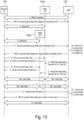
- Figure 13 illustrates an example message sequence chart for mobility related signaling between a remote UE 106, a first relay UE 104a, a second relay UE 104b and an eNB 102 for eNB 102 directed mobility for embodiments implementing pre-configured relay UEs and/or remote UEs as described above.
- the term eNB may loosely refer to a cell or RAN (Radio Access Network) node or transmission point (TP).
- the relay UE may belong to the same or different eNB or entity. When it belongs to different entity than the direct path of the remote UE, then additional signaling and context transfer might need to happen for the remote UE to switch between the direct path and relay UE path.
- the remote UE may be receiving data from multiple relay UEs, each associated with the same eNB/entity or different eNB/entity than the remote UE itself.
- Figure 14 illustrates an electronic device 1400 that may be, or may be incorporated into or otherwise part of, an eNB 102, a UE 104, 106, or some other type of electronic device in accordance with various embodiments.
- the electronic device1400 may be logic and/or circuitry that may be at least partially implemented in one or more of hardware, software, and/or firmware.
- the electronic device logic may include radio transmit logic 1402 and receive logic 1406 coupled to control logic 1404.
- the transmit 1402 and/or receive logic 1406 may be elements or modules of transceiver logic, as shown.
- the electronic device 1400 may be coupled with or include one or more plurality of antenna elements 1408 of one or more antennas.
- the electronic device 1400 and/or the components of the electronic device may be configured to perform operations similar to those described elsewhere in this disclosure.
- logic may refer to, be part of, or include an Application Specific Integrated Circuit (ASIC), an electronic circuit, a processor (shared, dedicated, or group), and/or memory (shared, dedicated, or group) that execute one or more software or firmware programs, a combinational logic circuit, and/or other suitable hardware components that provide the described functionality.
- ASIC Application Specific Integrated Circuit
- the logic may at be at least partially implemented in, or an element of, hardware, software, and/or firmware.
- the electronic device logic may be implemented in, or functions associated with the logic may be implemented by, one or more software or firmware modules.
- the electronic device of Figure 14 may be configured to perform one or more processes or methods such as processes or methods described herein.
- FIG. 15 illustrates, for one embodiment, an example system 1500 comprising radio frequency (RF) logic 1518, baseband logic 1512, application logic 1510, memory/storage 1512, display 1502, camera 1504, sensor 1506, and input/output (I/O) interface 1508, coupled with each other at least as shown.
- RF radio frequency
- the application logic 1510 may include one or more single-core or multi-core processors.
- the processor(s) may include any combination of general-purpose processors and dedicated processors (e.g., graphics processors, application processors, etc.).
- the processors may be coupled with memory/storage and configured to execute instructions stored in the memory/storage to enable various applications and/or operating systems running on the system.
- the baseband logic 1512 may include one or more single-core or multi-core processors.
- the processor(s) may include a baseband processor 1514 and/or additional or alternative processors 1516 that may be designed to implement functions or actions of the control logic 1404, transmit logic 1402, and/or receive logic 1406 described elsewhere herein.
- the baseband logic 1512 may handle various radio control functions that enables communication with one or more radio networks via the RF logic.
- the radio control functions may include, but are not limited to, signal modulation, encoding, decoding, radio frequency shifting, etc.
- the baseband logic 1512 may provide for communication compatible with one or more radio technologies.
- the baseband logic may support communication with an evolved universal terrestrial radio access network (EUTRAN) and/or other wireless metropolitan area networks (WMAN), a wireless local area network (WLAN), a wireless personal area network (WPAN).
- EUTRAN evolved universal terrestrial radio access network
- WMAN wireless metropolitan area networks
- WLAN wireless local area network
- WPAN wireless personal area network
- multi-mode baseband logic Embodiments in which the baseband logic is configured to support radio communications of more than one wireless protocol may be referred to as multi-mode baseband logic.
- baseband logic 1512 may include logic to operate with signals that are not strictly considered as being in a baseband frequency.
- baseband logic 1512 may include logic to operate with signals having an intermediate frequency, which is between a baseband frequency and a radio frequency.
- RF logic 1518 may enable communication with wireless networks using modulated electromagnetic radiation through a non-solid medium.
- the RF logic may include switches, filters, amplifiers, etc. to facilitate the communication with the wireless network.
- RF logic 1518 may include logic to operate with signals that are not strictly considered as being in a radio frequency.
- RF logic 1518 may include logic to operate with signals having an intermediate frequency, which is between a baseband frequency and a radio frequency.
- transmit logic 1402, control logic 1404, and/or receive logic 1406 discussed or described herein may be embodied in whole or in part in one or more of the RF logic 1518, the baseband logic 1512, and/or the application logic 1510.
- the term "logic" may refer to, be part of, or include an Application Specific Integrated Circuit (ASIC), an electronic circuit, a processor (shared, dedicated, or group), and/or memory (shared, dedicated, or group) that execute one or more software or firmware programs, a combinational logic circuit, and/or other suitable hardware components that provide the described functionality.
- the logic may at be at least partially implemented in, or an element of, hardware, software, and/or firmware.
- the electronic device logic may be implemented in, or functions associated with the logic may be implemented by, one or more software or firmware modules.
- the constituent components of the baseband logic 1512, the application logic 1510, and/or the memory/storage 1520 may be implemented together on a system on a chip (SOC).
- SOC system on a chip
- Memory/storage 1520 may be used to load and store data and/or instructions, for example, for system.
- Memory/storage for one embodiment may include any combination of suitable volatile memory (e.g., dynamic random access memory (DRAM)) and/or non-volatile memory (e.g., Flash memory).
- suitable volatile memory e.g., dynamic random access memory (DRAM)
- non-volatile memory e.g., Flash memory
- the I/O interface 1508 may include one or more user interfaces designed to enable user interaction with the system and/or peripheral component interfaces designed to enable peripheral component interaction with the system.
- User interfaces may include, but are not limited to a physical keyboard or keypad, a touchpad, a speaker, a microphone, etc.
- Peripheral component interfaces may include, but are not limited to, a non-volatile memory port, a universal serial bus (USB) port, an audio jack, and a power supply interface.
- USB universal serial bus
- sensor 1506 may include one or more sensing devices to determine environmental conditions and/or location information related to the system.
- the sensors may include, but are not limited to, a gyro sensor, an accelerometer, a proximity sensor, an ambient light sensor, and a positioning unit.
- the positioning unit may also be part of, or interact with, the baseband logic 1512 and/or RF logic 1518 to communicate with components of a positioning network, e.g., a global positioning system (GPS) satellite.
- GPS global positioning system
- the display 1502 may include a display (e.g., a liquid crystal display, a touch screen display, etc.).
- a display e.g., a liquid crystal display, a touch screen display, etc.
- system 1500 may be a mobile computing device such as, but not limited to, a laptop computing device, a tablet computing device, a netbook, an Ultrabook, a smartphone, etc.
- system may have more or less components, and/or different architectures.
- the RF logic 1518 and/or the baseband logic 1512 may be embodied in communication logic (not shown).
- the communication logic may include one or more single-core or multi-core processors and logic circuits to provide signal processing techniques, for example, encoding, modulation, filtering, converting, amplifying, etc., suitable to the appropriate communication interface over which communications will take place.
- the communication logic may communicate over wireline, optical, or wireless communication mediums.
- the communication logic may include the RF logic and/or baseband logic to provide for communication compatible with one or more radio technologies.
- the communication logic may support communication with an evolved universal terrestrial radio access network (EUTRAN) and/or other wireless metropolitan area networks (WMAN), a wireless local area network (WLAN), a wireless personal area network (WPAN).
- EUTRAN evolved universal terrestrial radio access network
- WMAN wireless metropolitan area networks
- WLAN wireless local area network
- WPAN wireless personal area network
- Embodiments of the technology herein may be described as related to the third generation partnership project (3GPP) long term evolution (LTE) or LTE-advanced (LTE-A) standards.
- 3GPP third generation partnership project
- LTE long term evolution
- LTE-A LTE-advanced
- terms or entities such as eNodeB (eNB), mobility management entity (MME), user equipment (UE), etc. may be used that may be viewed as LTE-related terms or entities.
- the technology may be used in or related to other wireless technologies such as the Institute of Electrical and Electronic Engineers (IEEE) 802.16 wireless technology (WiMax), IEEE 802.11 wireless technology (WiFi), various other wireless technologies such as global system for mobile communications (GSM), enhanced data rates for GSM evolution (EDGE), GSM EDGE radio access network (GERAN), universal mobile telecommunications system (UMTS), UMTS terrestrial radio access network (UTRAN), or other 2G, 3G, 4G, 5G, etc. technologies either already developed or to be developed.
- LTE-related terms such as eNB, MME, UE, etc.
- one or more entities or components may be used that may be considered to be equivalent or approximately equivalent to one or more of the LTE-based terms or entities.
- circuitry may refer to, be part of, or include an Application Specific Integrated Circuit (ASIC), an electronic circuit, a processor (shared, dedicated, or group), and/or memory (shared, dedicated, or group) that execute one or more software or firmware programs, a combinational logic circuit, and/or other suitable hardware components that provide the described functionality.
- ASIC Application Specific Integrated Circuit
- the circuitry may be implemented in, or functions associated with the circuitry may be implemented by, one or more software or firmware modules.
- circuitry may include logic, at least partially operable in hardware.
- FIG. 16 illustrates, for one embodiment, example components of a User Equipment (UE) device 1600.
- the UE device 1600 may include application circuitry 1602, baseband circuitry 1604, Radio Frequency (RF) circuitry 1606, front-end module (FEM) circuitry 1608 and one or more antennas 1610, coupled together at least as shown.
- RF Radio Frequency
- FEM front-end module
- the application circuitry 1602 may include one or more application processors.
- the application circuitry 1602 may include circuitry such as, but not limited to, one or more single-core or multi-core processors.
- the processor(s) may include any combination of general-purpose processors and dedicated processors (e.g., graphics processors, application processors, etc.).
- the processors may be coupled with and/or may include memory/storage and may be configured to execute instructions stored in the memory/storage to enable various applications and/or operating systems to run on the system.
- the baseband circuitry 1604 may include circuitry such as, but not limited to, one or more single-core or multi-core processors.
- the baseband circuitry 1604 may include one or more baseband processors and/or control logic to process baseband signals received from a receive signal path of the RF circuitry 1606 and to generate baseband signals for a transmit signal path of the RF circuitry 1606.
- Baseband processing circuity 1604 may interface with the application circuitry 1602 for generation and processing of the baseband signals and for controlling operations of the RF circuitry 1606.
- the baseband circuitry 1604 may include a second generation (2G) baseband processor 1604a, third generation (3G) baseband processor 1604b, fourth generation (4G) baseband processor 1604c, and/or other baseband processor(s) 1604d for other existing generations, generations in development or to be developed in the future (e.g., fifth generation (5G), 6G, etc.).
- the baseband circuitry 1604 e.g., one or more of baseband processors 1604a-d
- the radio control functions may include, but are not limited to, signal modulation/demodulation, encoding/decoding, radio frequency shifting, etc.
- modulation/demodulation circuitry of the baseband circuitry 1604 may include Fast-Fourier Transform (FFT), precoding, and/or constellation mapping/demapping functionality.
- FFT Fast-Fourier Transform
- encoding/decoding circuitry of the baseband circuitry 1604 may include convolution, tail-biting convolution, turbo, Viterbi, and/or Low Density Parity Check (LDPC) encoder/decoder functionality.
- LDPC Low Density Parity Check
- the baseband circuitry 1604 may include elements of a protocol stack such as, for example, elements of an evolved universal terrestrial radio access network (EUTRAN) protocol including, for example, physical (PHY), media access control (MAC), radio link control (RLC), packet data convergence protocol (PDCP), and/or radio resource control (RRC) elements.
- EUTRAN evolved universal terrestrial radio access network
- a central processing unit (CPU) 1604e of the baseband circuitry 1604 may be configured to run elements of the protocol stack for signaling of the PHY, MAC, RLC, PDCP and/or RRC layers.
- the baseband circuitry may include one or more audio digital signal processor(s) (DSP) 1604f.
- DSP audio digital signal processor
- the audio DSP(s) 104f may be include elements for compression/decompression and echo cancellation and may include other suitable processing elements in other embodiments.
- Components of the baseband circuitry may be suitably combined in a single chip, a single chipset, or disposed on a same circuit board in some embodiments.
- some or all of the constituent components of the baseband circuitry 1604 and the application circuitry 1602 may be implemented together such as, for example, on a system on a chip (SOC).
- SOC system on a chip
- the baseband circuitry 1604 may provide for communication compatible with one or more radio technologies.
- the baseband circuitry 1604 may support communication with an evolved universal terrestrial radio access network (EUTRAN) and/or other wireless metropolitan area networks (WMAN), a wireless local area network (WLAN), a wireless personal area network (WPAN).
- EUTRAN evolved universal terrestrial radio access network
- WMAN wireless metropolitan area networks
- WLAN wireless local area network
- WPAN wireless personal area network
- multi-mode baseband circuitry Embodiments in which the baseband circuitry 1604 is configured to support radio communications of more than one wireless protocol.
- RF circuitry 1606 may enable communication with wireless networks using modulated electromagnetic radiation through a non-solid medium.
- the RF circuitry 1606 may include switches, filters, amplifiers, etc. to facilitate the communication with the wireless network.
- RF circuitry 1606 may include a receive signal path which may include circuitry to down-convert RF signals received from the FEM circuitry 1608 and provide baseband signals to the baseband circuitry 1604.
- RF circuitry 1606 may also include a transmit signal path which may include circuitry to up-convert baseband signals provided by the baseband circuitry 1604 and provide RF output signals to the FEM circuitry 1608 for transmission.
- the RF circuitry 1606 may include a receive signal path and a transmit signal path.
- the receive signal path of the RF circuitry 1606 may include mixer circuitry 1606a, amplifier circuitry 1606b and filter circuitry 1606c.
- the transmit signal path of the RF circuitry 1606 may include filter circuitry 1606c and mixer circuitry 1606a.
- RF circuitry 1606 may also include synthesizer circuitry 1606d for synthesizing a frequency for use by the mixer circuitry 1606a of the receive signal path and the transmit signal path.
- the mixer circuitry 1606a of the receive signal path may be configured to down-convert RF signals received from the FEM circuitry 1608 based on the synthesized frequency provided by synthesizer circuitry 1606d.
- the amplifier circuitry 1606b may be configured to amplify the down-converted signals and the filter circuitry 1606c may be a low-pass filter (LPF) or band-pass filter (BPF) configured to remove unwanted signals from the down-converted signals to generate output baseband signals.
- LPF low-pass filter
- BPF band-pass filter
- Output baseband signals may be provided to the baseband circuitry 1604 for further processing.
- the output baseband signals may be zero-frequency baseband signals, although this is not a requirement.
- mixer circuitry 1606a of the receive signal path may comprise passive mixers, although the scope of the embodiments is not limited in this respect.
- the mixer circuitry 1606a of the transmit signal path may be configured to up-convert input baseband signals based on the synthesized frequency provided by the synthesizer circuitry 1606d to generate RF output signals for the FEM circuitry 1608.
- the baseband signals may be provided by the baseband circuitry 1604 and may be filtered by filter circuitry 1606c.
- the filter circuitry 1606c may include a low-pass filter (LPF), although the scope of the embodiments is not limited in this respect.
- LPF low-pass filter
- the mixer circuitry 1606a of the receive signal path and the mixer circuitry 1606a of the transmit signal path may include two or more mixers and may be arranged for quadrature downconversion and/or upconversion respectively.
- the mixer circuitry 1606a of the receive signal path and the mixer circuitry 1606a of the transmit signal path may include two or more mixers and may be arranged for image rejection (e.g., Hartley image rejection).
- the mixer circuitry 1606a of the receive signal path and the mixer circuitry 1606a may be arranged for direct downconversion and/or direct upconversion, respectively.
- the mixer circuitry 1606a of the receive signal path and the mixer circuitry 1606a of the transmit signal path may be configured for super-heterodyne operation.
- the output baseband signals and the input baseband signals may be analog baseband signals, although the scope of the embodiments is not limited in this respect.
- the output baseband signals and the input baseband signals may be digital baseband signals.
- the RF circuitry 1606 may include analog-to-digital converter (ADC) and digital-to-analog converter (DAC) circuitry and the baseband circuitry 1604 may include a digital baseband interface to communicate with the RF circuitry 1606.
- ADC analog-to-digital converter
- DAC digital-to-analog converter
- a separate radio IC circuitry may be provided for processing signals for each spectrum, although the scope of the embodiments is not limited in this respect.
- the synthesizer circuitry 1606d may be a fractional-N synthesizer or a fractional N/N+1 synthesizer, although the scope of the embodiments is not limited in this respect as other types of frequency synthesizers may be suitable.
- synthesizer circuitry 1606d may be a delta-sigma synthesizer, a frequency multiplier, or a synthesizer comprising a phase-locked loop with a frequency divider.
- the synthesizer circuitry 1606d may be configured to synthesize an output frequency for use by the mixer circuitry 1606a of the RF circuitry 1606 based on a frequency input and a divider control input. In some embodiments, the synthesizer circuitry 1606d may be a fractional N/N+1 synthesizer.
- frequency input may be provided by a voltage controlled oscillator (VCO), although that is not a requirement.
- VCO voltage controlled oscillator
- Divider control input may be provided by either the baseband circuitry 1604 or the applications processor 1602 depending on the desired output frequency.
- a divider control input (e.g., N) may be determined from a look-up table based on a channel indicated by the applications processor 1602.
- Synthesizer circuitry 1606d of the RF circuitry 1606 may include a divider, a delay-locked loop (DLL), a multiplexer and a phase accumulator.
- the divider may be a dual modulus divider (DMD) and the phase accumulator may be a digital phase accumulator (DPA).
- the DMD may be configured to divide the input signal by either N or N+1 (e.g., based on a carry out) to provide a fractional division ratio.
- the DLL may include a set of cascaded, tunable, delay elements, a phase detector, a charge pump and a D-type flip-flop.
- the delay elements may be configured to break a VCO period up into Nd equal packets of phase, where Nd is the number of delay elements in the delay line.
- Nd is the number of delay elements in the delay line.
- synthesizer circuitry 1606d may be configured to generate a carrier frequency as the output frequency, while in other embodiments, the output frequency may be a multiple of the carrier frequency (e.g., twice the carrier frequency, four times the carrier frequency) and used in conjunction with quadrature generator and divider circuitry to generate multiple signals at the carrier frequency with multiple different phases with respect to each other.
- the output frequency may be a LO frequency (f LO ).
- the RF circuitry 1606 may include an IQ/polar converter.
- FEM circuitry 1608 may include a receive signal path which may include circuitry configured to operate on RF signals received from one or more antennas 1610, amplify the received signals and provide the amplified versions of the received signals to the RF circuitry 1606 for further processing.
- FEM circuitry 1608 may also include a transmit signal path which may include circuitry configured to amplify signals for transmission provided by the RF circuitry 1606 for transmission by one or more of the one or more antennas 1610.
- the FEM circuitry 1608 may include a TX/RX switch to switch between transmit mode and receive mode operation.
- the FEM circuitry may include a receive signal path and a transmit signal path.
- the receive signal path of the FEM circuitry may include a low-noise amplifier (LNA) to amplify received RF signals and provide the amplified received RF signals as an output (e.g., to the RF circuitry 1606).
- the transmit signal path of the FEM circuitry 1608 may include a power amplifier (PA) to amplify input RF signals (e.g., provided by RF circuitry 1606), and one or more filters to generate RF signals for subsequent transmission (e.g., by one or more of the one or more antennas 1610.
- PA power amplifier
- the implemented wireless network may be a 3rd Generation Partnership Project's long term evolution (LTE) advanced wireless communication standard, which may include, but is not limited to releases 8, 9, 10, 11 and 12, or later, of the 3GPP's LTE-A standards.
- LTE long term evolution
Landscapes
- Engineering & Computer Science (AREA)
- Computer Networks & Wireless Communication (AREA)
- Signal Processing (AREA)
- Mobile Radio Communication Systems (AREA)
Claims (15)
- Un appareil destiné à un équipement utilisateur, UE, distant (106) pour une utilisation dans un réseau de communication sans fil, l'appareil comprenant :une première entité ;une seconde entité ; etune logique de contrôle (308) configurée pour :recevoir une unité de données de service dérivée d'un paquet en protocole internet, IP ;en réponse à la réception de l'unité de données de service :déterminer de communiquer à une station de base via la première entité l'unité de données de service en utilisant une interface Uu dans un premier mode de fonctionnement (310a), oudéterminer de communiquer à la station de base via la seconde entité l'unité de données de service via un premier UE relai en utilisant une interface sidelink (310b) dans un second mode, relai, de fonctionnement.
- L'appareil de la revendication 1, dans lequel l'unité de données de service comprend une unité de données de service de contrôle d'accès au support, MAC.
- L'appareil de la revendication 1, dans lequel l'unité de données de service comprend une unité de données de service de contrôle de liaison radio, RLC.
- L'appareil de la revendication 1, dans lequel l'unité de données de service comprend une unité de données de service de protocole de convergence de données en paquets, PDCP.
- L'appareil de l'une des revendications précédentes, dans lequel une unité de données en paquets comprenant l'unité de données de service comprend en outre un entête de protocole de relai, l'entête de protocole de relai comprenant un identifiant d'UE ; éventuellement dans lequel une pluralité d'UE distants doivent communiquer avec le premier UE relai, et dans lequel l'identifiant d'UE doit comprendre un ID court qui identifie de façon univoque l'UE distant parmi la pluralité d'UE distants communiquant avec le premier UE relai.
- L'appareil de l'une des revendications précédentes, dans lequel la détermination de communiquer l'unité de données de service en utilisant une interface Uu est basée sur une qualité de signal de l'interface Uu.
- L'appareil de l'une des revendications précédentes, dans lequel la détermination de communiquer l'unité de données de service en utilisant une interface sidelink est basée sur une qualité de signal de l'interface sidelink.
- L'appareil de l'une des revendications précédentes, dans lequel la logique de contrôle est en outre configurée pour :
déterminer, sur la base d'au moins l'une d'entre une qualité de signal de l'interface sidelink ou d'une qualité de signal de l'interface Uu, de fonctionner dans le premier mode de fonctionnement ou dans le second mode, relai, de fonctionnement. - L'appareil de l'une des revendications précédentes, dans lequel la logique de contrôle est en outre configurée pour :
recevoir, en provenance de la station de base, une indication de fonctionner dans le premier mode de fonctionnement ou dans le second mode, relai, de fonctionnement. - Un appareil destiné à une utilisation dans une station de base dans un réseau de communication sans fil, la station de base (102) comprenant :une première entité pour communiquer avec un équipement utilisateur relai ;une seconde entité pour communiquer avec un équipement utilisateur distant ; etune logique de contrôle (336) pour :recevoir une unité de données de service dérivées d'une unité de paquets en protocole internet, IP, à communiquer à un équipement utilisateur, UE, distant ;en réponse à la réception de l'unité de données de service :déterminer de communiquer à un UE relai via la première entité l'unité de données de service dans un premier mode, relai, de fonctionnement (340b) ; etdéterminer de communiquer à l'UE via la seconde entité l'unité de données de service distant dans un second mode de fonctionnement (304a).
- L'appareil de la revendication 10, dans lequel la logique de contrôle sert en outre à produire un message de configuration pour configurer l'UE relai afin de relayer une unité de données de service vers l'UE distant.
- L'appareil de la revendication 10 ou de la revendication 11, dans lequel l'unité de données de service comprend une unité de données de service de contrôle d'accès au support, MAC.
- L'appareil de la revendication 10 ou de la revendication 11, dans lequel l'unité de données de service comprend une unité de données de service de contrôle de liaison radio, RLC.
- L'appareil de la revendication 10 ou de la revendication 11, dans lequel l'unité de données de service comprend une unité de données de service de protocole de convergence de données en paquets, PDCP.
- L'appareil de l'une des revendications 7 à 14, dans lequel la logique de contrôle sert en outre à :obtenir un message de compte rendu de mesure en provenance de l'UE distant, le message de compte rendu de mesure incluant une indication d'au moins un UE relai à proximité de l'UE distant ;sélectionner un trajet de communication pour l'UE distant à relayer via l'UE relai, sur la base du message de compte rendu de mesure ;transmettre un message de reconfiguration de relai, sur la base du trajet de communication sélectionné ;recevoir les données en provenance de l'UE distant via un nouvel UE relai ; etdans lequel la réception de données via le nouvel UE relai comprend une indication d'un basculement de trajet par l'UE distant.
Applications Claiming Priority (2)
| Application Number | Priority Date | Filing Date | Title |
|---|---|---|---|
| US201562196138P | 2015-07-23 | 2015-07-23 | |
| PCT/US2015/000296 WO2017014716A1 (fr) | 2015-07-23 | 2015-12-23 | Protocoles relais de la couche 2 et procédé relais de mobilité |
Publications (2)
| Publication Number | Publication Date |
|---|---|
| EP3326423A1 EP3326423A1 (fr) | 2018-05-30 |
| EP3326423B1 true EP3326423B1 (fr) | 2024-04-17 |
Family
ID=55182534
Family Applications (1)
| Application Number | Title | Priority Date | Filing Date |
|---|---|---|---|
| EP15826208.9A Active EP3326423B1 (fr) | 2015-07-23 | 2015-12-23 | Protocoles relais de la couche 2 et procédé relais de mobilité |
Country Status (5)
| Country | Link |
|---|---|
| US (3) | US10602550B2 (fr) |
| EP (1) | EP3326423B1 (fr) |
| KR (1) | KR102568265B1 (fr) |
| CN (1) | CN108029148B (fr) |
| WO (1) | WO2017014716A1 (fr) |
Families Citing this family (148)
| Publication number | Priority date | Publication date | Assignee | Title |
|---|---|---|---|---|
| WO2017014716A1 (fr) | 2015-07-23 | 2017-01-26 | Intel IP Corporation | Protocoles relais de la couche 2 et procédé relais de mobilité |
| CN107852765B (zh) * | 2015-07-29 | 2022-03-08 | 夏普株式会社 | 用于设备到设备中继过程的方法 |
| EP3376788B1 (fr) * | 2015-12-31 | 2019-09-18 | Huawei Technologies Co., Ltd. | Procédé permettant à un équipement d'utilisateur (ue) d'accéder à un réseau, entité de réseau central, station de base, et premier ue |
| EP3402269B1 (fr) * | 2016-01-27 | 2021-01-13 | Huawei Technologies Co., Ltd. | Procédé de communication et dispositif de communication |
| US20190059015A1 (en) * | 2016-02-24 | 2019-02-21 | Lg Electronics Inc. | Method and apparatus for relaying using non-3gpp radio access technology in wireless communication system |
| CN108521851B (zh) * | 2016-03-30 | 2021-06-29 | Oppo广东移动通信有限公司 | 中继传输的方法、装置和计算机可读存储介质 |
| EP3424263B1 (fr) | 2016-04-01 | 2020-08-19 | Sony Corporation | Dispositif de communication, équipement de communication, et procédé |
| CN108886682B (zh) | 2016-06-03 | 2022-04-15 | Oppo广东移动通信有限公司 | 中继传输的方法和装置 |
| WO2018010820A1 (fr) * | 2016-07-15 | 2018-01-18 | Sony Mobile Communications Inc. | Établissement ou reprise d'une connexion de communication sans fil dans un réseau de communication sans fil |
| CN109792679B (zh) * | 2016-08-11 | 2020-12-04 | 华为技术有限公司 | 通信方法、装置及设备 |
| WO2018061759A1 (fr) * | 2016-09-30 | 2018-04-05 | 京セラ株式会社 | Procédé de commande de communication |
| AU2016424413B2 (en) * | 2016-09-30 | 2021-01-28 | Huawei Technologies Co., Ltd. | Data transmission method, device, and system |
| CN109417695B (zh) * | 2017-01-10 | 2020-10-23 | 华为技术有限公司 | 一种通信路径转换方法及设备 |
| US10292087B2 (en) | 2017-02-01 | 2019-05-14 | Futurewei Technologies, Inc. | System and method for access barring |
| CN108391285B (zh) * | 2017-02-03 | 2023-05-05 | 中兴通讯股份有限公司 | 一种设备直通系统的通信方法、数据转发方法及装置 |
| WO2018165150A1 (fr) * | 2017-03-10 | 2018-09-13 | Intel IP Corporation | Nœud b évolué (enb), équipement utilisateur (ue) et procédés de commutation entre une communication directe et indirecte pour un agencement de relais |
| US12047826B2 (en) | 2017-03-10 | 2024-07-23 | Apple Inc. | Evolved node-b (eNB), user equipment (UE) and methods of switching between direct and indirect communication for a relay arrangement |
| US20210076254A1 (en) * | 2017-03-23 | 2021-03-11 | Nokia Technologies Oy | Handling of user equipment identifiers over pc5 interface in pc5-based user equipment to network relay |
| WO2018176227A1 (fr) * | 2017-03-28 | 2018-10-04 | 华为技术有限公司 | Procédé et appareil de traitement de données |
| WO2018176416A1 (fr) | 2017-03-31 | 2018-10-04 | 华为技术有限公司 | Procédé, appareil, et système de communication à relais |
| EP3621405A4 (fr) * | 2017-04-28 | 2020-04-01 | Guangdong Oppo Mobile Telecommunications Corp., Ltd. | Procédé de configuration de connexion de réseau et produit connexe |
| CN108810854A (zh) * | 2017-04-28 | 2018-11-13 | 索尼公司 | 电子设备及由电子设备执行的方法 |
| JP2018191130A (ja) * | 2017-05-02 | 2018-11-29 | ソニー株式会社 | 通信装置及び通信方法 |
| US11219054B2 (en) | 2017-05-05 | 2022-01-04 | Qualcomm Incorporated | Relaying in a device-to-device communication system |
| US10912114B2 (en) * | 2017-05-05 | 2021-02-02 | Qualcomm Incorporated | Relaying in a device-to-device communication system |
| EP3619989B1 (fr) | 2017-05-05 | 2025-04-09 | Motorola Mobility LLC | Indication d'informations de commande de liaison latérale |
| US10893557B2 (en) | 2017-05-05 | 2021-01-12 | Qualcomm Incorporated | Relaying in a device-to-device communication system |
| US10469358B2 (en) * | 2017-05-18 | 2019-11-05 | Qualcomm Incorporated | Wireless multihop relay |
| WO2018224128A1 (fr) * | 2017-06-06 | 2018-12-13 | Motorola Mobility Llc | Commutation de modes de communication (accès direct et indirect d'ue) |
| WO2019024105A1 (fr) | 2017-08-04 | 2019-02-07 | Oppo广东移动通信有限公司 | Procédé de prise en charge de réplication de données, dispositif terminal de transmission et dispositif terminal de réception |
| CN114513822B (zh) * | 2017-08-11 | 2024-05-03 | 华为技术有限公司 | 一种路径转换方法、相关装置及系统 |
| CN109756925B (zh) * | 2017-08-26 | 2022-04-12 | 华为技术有限公司 | 一种通过中继的通信处理方法和装置 |
| WO2019136606A1 (fr) * | 2018-01-09 | 2019-07-18 | Oppo广东移动通信有限公司 | Procédé de transmission relais, et nœud relais |
| WO2019209784A1 (fr) * | 2018-04-23 | 2019-10-31 | Kyocera Corporation | Procédé de détermination du nombre de répétitions pour une diffusion générale multi-utilisateur dans des déploiements de l'iot |
| US10904947B2 (en) * | 2018-05-16 | 2021-01-26 | Huawei Technologies Co., Ltd. | Message and system for application function influence on traffic routing |
| US11672035B2 (en) * | 2018-06-14 | 2023-06-06 | Lg Electronics Inc. | Method and apparatus for performing sidelink communication by UE in NR V2X |
| CN110611943A (zh) * | 2018-06-15 | 2019-12-24 | 海信集团有限公司 | 一种重选Relay UE的方法和设备 |
| CN110611940A (zh) * | 2018-06-15 | 2019-12-24 | 海信集团有限公司 | 一种选择Relay UE的方法和设备 |
| US10485053B1 (en) * | 2018-06-22 | 2019-11-19 | Nokia Solutions And Networks Oy | Method and apparatus for pre-empting evolved node B control plane collisions |
| EP3821680B1 (fr) * | 2018-07-12 | 2023-10-04 | Koninklijke KPN N.V. | Relais à sauts multiples dans un réseau de communication mobile |
| CN113473410B (zh) * | 2018-09-28 | 2025-08-12 | 华为技术有限公司 | 一种通信方法及装置 |
| CN111147193B (zh) * | 2018-11-02 | 2022-04-15 | 大唐移动通信设备有限公司 | 一种车联网的重传请求方法、终端和网络侧设备 |
| CN111224759B (zh) * | 2018-11-23 | 2022-08-30 | 大唐移动通信设备有限公司 | 一种承载配置方法、装置及设备 |
| CN111526543A (zh) * | 2019-02-02 | 2020-08-11 | 索尼公司 | 电子设备、通信方法和存储介质 |
| US12127253B2 (en) | 2019-02-13 | 2024-10-22 | Mediatek Singapore Pte. Ltd. | Channel access priority class for signaling radio bearers in new radio unlicensed |
| CN111586765B (zh) | 2019-02-15 | 2023-01-13 | 华为技术有限公司 | 中继通信的方法和装置 |
| US12022551B2 (en) | 2019-03-08 | 2024-06-25 | FG Innovation Company Limited | Method and apparatus for sidelink communication managements |
| CN113455100B (zh) * | 2019-03-29 | 2022-06-14 | 华为技术有限公司 | 用于中继通信的方法和装置 |
| US12137371B2 (en) * | 2019-04-05 | 2024-11-05 | Qualcomm Incorporated | On-demand relaying of messages for side-link communications |
| US12048055B1 (en) * | 2019-04-25 | 2024-07-23 | T-Mobile Innovations Llc | Wireless bearer enhancement between a wireless relay and a wireless access point |
| CN111294859B (zh) * | 2019-05-24 | 2021-09-07 | 展讯通信(上海)有限公司 | 数据分组的传输方法及装置、存储介质、终端 |
| WO2021045859A1 (fr) * | 2019-09-06 | 2021-03-11 | Convida Wireless, Llc | Sélection de trajet ou commutation de trajet et charge pour communication de service de proximité |
| US11765616B2 (en) * | 2019-11-19 | 2023-09-19 | Huawei Technologies Co., Ltd. | Methods, apparatus, and systems for UE cooperation with UE relaying |
| WO2021097801A1 (fr) * | 2019-11-22 | 2021-05-27 | Mediatek Singapore Pte. Ltd. | Procédés et appareil de routage de paquet pour un relais de liaison latérale |
| CN118042527A (zh) * | 2019-11-26 | 2024-05-14 | 联发科技(新加坡)私人有限公司 | 用于侧链路的协作通信的方法和设备 |
| WO2021134162A1 (fr) * | 2019-12-30 | 2021-07-08 | Mediatek Singapore Pte. Ltd. | Procédés et appareil de distribution d'informations de système pour relais de liaison latérale |
| CN118175565A (zh) * | 2019-12-31 | 2024-06-11 | 华为技术有限公司 | 通信方法及装置 |
| CN114830717B (zh) * | 2019-12-31 | 2024-10-18 | 华为技术有限公司 | 一种通信方法及装置 |
| WO2021134756A1 (fr) * | 2020-01-02 | 2021-07-08 | Oppo广东移动通信有限公司 | Procédé et dispositif de commutation de liaison, et dispositif de communication |
| WO2021138756A1 (fr) * | 2020-01-06 | 2021-07-15 | Mediatek Singapore Pte. Ltd. | Procédés et appareil d'acheminement pour relais de liaison latérale |
| WO2021138897A1 (fr) | 2020-01-10 | 2021-07-15 | Mediatek Singapore Pte. Ltd. | Procédés et appareil d'établissement de connexion et de mappage de porteuse pour un relais d'équipement utilisateur (ue) à réseau |
| WO2021146999A1 (fr) * | 2020-01-22 | 2021-07-29 | Mediatek Singapore Pte. Ltd. | Procédés et appareil d'établissement de canal de relais de liaison latérale |
| EP4101253B1 (fr) * | 2020-02-03 | 2024-08-28 | Telefonaktiebolaget LM Ericsson (publ) | Section de chemin entre uu et pc5 |
| WO2021155526A1 (fr) * | 2020-02-06 | 2021-08-12 | Mediatek Singapore Pte. Ltd. | Procédés et appareil de continuité de service basée sur une commutation de trajet pour un relais d'équipement utilisateur (ue) à réseau |
| CN121418946A (zh) * | 2020-02-13 | 2026-01-27 | 中兴通讯股份有限公司 | sidelink中继通信方法、通信设备及存储介质 |
| CN111901836A (zh) * | 2020-02-13 | 2020-11-06 | 中兴通讯股份有限公司 | 链路切换、链路切换配置方法、装置、通信节点及介质 |
| US11924895B2 (en) * | 2020-02-14 | 2024-03-05 | Qualcomm Incorporated | Techniques for new radio layer two relay |
| WO2021168632A1 (fr) * | 2020-02-24 | 2021-09-02 | Oppo广东移动通信有限公司 | Procédé de relais, procédé, appareil et dispositif de production de table de routage, ainsi que support de stockage |
| US20210298063A1 (en) * | 2020-03-18 | 2021-09-23 | Qualcomm Incorporated | Joint resource assignment for a user equipment (ue) and a relay ue for uplink and sidelink transmissions |
| CN113453272B (zh) * | 2020-03-25 | 2023-11-10 | 维沃移动通信有限公司 | 副链路中继架构中的切换方法和设备 |
| EP4436311A3 (fr) * | 2020-03-26 | 2024-12-04 | Kyocera Corporation | Procédé de commande de communication |
| WO2021195867A1 (fr) * | 2020-03-30 | 2021-10-07 | Mediatek Singapore Pte. Ltd. | Mise en correspondance de porteuse pour relais d'ue à ue |
| EP4101255A1 (fr) * | 2020-03-31 | 2022-12-14 | Sony Group Corporation | Procédés, équipement d'infrastructure et réseaux de communication sans fil |
| CN113497799B (zh) * | 2020-04-08 | 2022-09-16 | 维沃移动通信有限公司 | 协议架构确定方法、装置及设备 |
| US11838894B2 (en) * | 2020-04-08 | 2023-12-05 | Qualcomm Incorporated | Quality of service or priority configuration for relay user equipment |
| CN115398945A (zh) * | 2020-04-15 | 2022-11-25 | 瑞典爱立信有限公司 | 管理副链路通信安全 |
| WO2021212290A1 (fr) * | 2020-04-20 | 2021-10-28 | Oppo广东移动通信有限公司 | Procédé et appareil de traitement de porteuses radio |
| WO2021212260A1 (fr) | 2020-04-20 | 2021-10-28 | Qualcomm Incorporated | Gestion de mobilité entre un trajet uu et un trajet de relais pc5 |
| CN113573422B (zh) * | 2020-04-28 | 2023-10-20 | 维沃移动通信有限公司 | 远端终端的连接管理方法、终端及网络侧设备 |
| US12058783B2 (en) | 2020-05-11 | 2024-08-06 | Qualcomm Incorporated | Relay adaptation protocol layer configuration |
| CN115552974A (zh) * | 2020-05-12 | 2022-12-30 | 高通股份有限公司 | 用于从无线通信设备向网络传送数据的侧链路中继路由选项 |
| WO2021236894A1 (fr) * | 2020-05-20 | 2021-11-25 | Convida Wireless, Llc | Gestion de connectivité de relais de liaison latérale |
| CN113709692B (zh) * | 2020-05-21 | 2024-07-09 | 上海朗帛通信技术有限公司 | 一种用于中继传输的方法和装置 |
| US11849382B2 (en) * | 2020-05-28 | 2023-12-19 | Huawei Technologies Co., Ltd. | Methods, apparatus, and systems for fast path switching in wireless communications with user equipment (UE) cooperation |
| US11758596B2 (en) * | 2020-06-18 | 2023-09-12 | Asustek Computer Inc. | Method and apparatus for a relay to transmit a direct communication request message in a wireless communication system |
| CN113825108B (zh) * | 2020-06-18 | 2022-11-22 | 华硕电脑股份有限公司 | 无线通信系统中用户设备传送直接通信请求消息的方法和设备 |
| CN113825115B (zh) * | 2020-06-19 | 2024-10-18 | 上海朗帛通信技术有限公司 | 一种用于中继传输的方法和装置 |
| KR102627692B1 (ko) * | 2020-06-29 | 2024-01-23 | 아서스테크 컴퓨터 인코포레이션 | 무선 통신 시스템에서 릴레이가 사이드링크 사용자 단말(ue) 성능 정보를 보고하기 위한 방법 및 장치 |
| CN113873586B (zh) * | 2020-06-30 | 2024-10-29 | 华为技术有限公司 | 一种通信路径切换方法、装置及系统 |
| CN113891292B (zh) * | 2020-07-01 | 2024-01-12 | 华硕电脑股份有限公司 | 无线通信系统中建立用于ue间中继通信的侧链路无线电承载的方法和设备 |
| US12483966B2 (en) | 2020-07-17 | 2025-11-25 | Lg Electronics Inc. | Method and apparatus for performing relaying on basis of data inactivity timer |
| CN113973284B (zh) * | 2020-07-24 | 2023-12-08 | 华为技术有限公司 | 侧行链路信令无线承载配置的方法和通信装置 |
| CN114071490B (zh) * | 2020-07-30 | 2025-02-25 | 维沃移动通信有限公司 | 副链路中继架构中的配置方法和终端 |
| CN114071473A (zh) * | 2020-08-05 | 2022-02-18 | 索尼公司 | 电子设备、无线通信方法和计算机可读存储介质 |
| CN116171645A (zh) * | 2020-08-06 | 2023-05-26 | 联想(新加坡)私人有限公司 | 侧链路设备发现 |
| US11382027B2 (en) * | 2020-08-17 | 2022-07-05 | Qualcomm Incorporated | Layer 2 remote radio head configuration |
| WO2022040830A1 (fr) * | 2020-08-23 | 2022-03-03 | Qualcomm Incorporated | Relais de communication sans fil à une entité de réseau sur la base d'une connexion à distance |
| WO2022052092A1 (fr) * | 2020-09-14 | 2022-03-17 | Mediatek Singapore Pte. Ltd. | Établissement de connexion pour un relais ue-réseau de couche 2 |
| JP7549135B2 (ja) * | 2020-09-25 | 2024-09-10 | テレフオンアクチーボラゲット エルエム エリクソン(パブル) | パス切り替えのための方法および装置 |
| US20230379989A1 (en) * | 2020-10-16 | 2023-11-23 | Hyundai Motor Company | Method and device for relay communication on sidelink |
| US11659468B2 (en) * | 2020-10-22 | 2023-05-23 | Electronics And Telecommunications Research Institute | Method and apparatus for link configuration and routing of relay system |
| CN114501482B (zh) * | 2020-10-23 | 2024-04-26 | 维沃移动通信有限公司 | 无线通信方法、装置、中继设备、远端设备和基站 |
| US11743907B2 (en) * | 2020-10-23 | 2023-08-29 | Qualcomm Incorporated | Direct transport block (TB) forwarding in relaying operations |
| US12581552B2 (en) | 2020-10-27 | 2026-03-17 | Hyundai Motor Company | Method and device for relay communication in sidelink |
| WO2022092865A1 (fr) | 2020-10-29 | 2022-05-05 | 현대자동차주식회사 | Procédé et dispositif de récupération de liaison pendant une communication de relais de liaison latérale |
| KR20220057457A (ko) * | 2020-10-29 | 2022-05-09 | 현대자동차주식회사 | 사이드링크 릴레이 통신에서 링크 복구를 위한 방법 및 장치 |
| KR102736339B1 (ko) | 2020-11-16 | 2024-11-29 | 아서스테크 컴퓨터 인코포레이션 | 무선 통신 시스템에서 uu 무선 베어러 대 pc5 무선 링크 제어(rlc) 베어러 매핑을 위한 방법 및 장치 |
| WO2022120653A1 (fr) * | 2020-12-09 | 2022-06-16 | 华为技术有限公司 | Procédé, appareil et système de routage |
| US12557166B2 (en) * | 2020-12-18 | 2026-02-17 | Lenovo (Beijing) Limited | Method and apparatus for path switch in a wireless communication system |
| US11601968B2 (en) * | 2020-12-18 | 2023-03-07 | Qualcomm Incorporated | Splitting and concatenating of media access control (MAC) protocol data units (PDUs) for direct transport block (TB) forwarding in relaying operations |
| EP4275364A4 (fr) * | 2021-01-05 | 2025-01-22 | Qualcomm Incorporated | Procédures de transfert intercellulaire direct pour mobilité de relais l2 |
| KR20230129429A (ko) * | 2021-01-13 | 2023-09-08 | 퀄컴 인코포레이티드 | 사이드링크 인터페이스를 위한 중계 적응 계층 구성 |
| WO2022151003A1 (fr) * | 2021-01-13 | 2022-07-21 | Qualcomm Incorporated | Rapport de mesure et procédures de transfert intercellulaire entre des trajets de relais |
| KR20220103514A (ko) * | 2021-01-15 | 2022-07-22 | 한국전자통신연구원 | 고속 열차 환경에서의 통신 방법 및 장치 |
| CN114793350A (zh) * | 2021-01-25 | 2022-07-26 | 维沃移动通信有限公司 | 路径切换的方法、终端及网络侧设备 |
| WO2022160117A1 (fr) * | 2021-01-27 | 2022-08-04 | Lenovo (Beijing) Limited | Procédé et appareil de transfert et de rétablissement dans un système de communication sans fil |
| CN115150904B (zh) * | 2021-03-30 | 2024-06-04 | 维沃移动通信有限公司 | 通信路径的切换方法、装置及终端 |
| EP4315990A1 (fr) * | 2021-03-31 | 2024-02-07 | Interdigital Patent Holdings, Inc. | Gestion dynamique de plan d'utilisateur |
| CN115243337B (zh) * | 2021-04-23 | 2024-09-24 | 华为技术有限公司 | 数据传输方法及装置 |
| WO2022227022A1 (fr) | 2021-04-30 | 2022-11-03 | Qualcomm Incorporated | Opérations de relais dans une communication sans fil |
| WO2022232959A1 (fr) * | 2021-05-03 | 2022-11-10 | Qualcomm Incorporated | Mise à jour d'identifiant de nœud de relais |
| US20240259892A1 (en) * | 2021-05-27 | 2024-08-01 | Telefonaktiebolaget Lm Ericsson (Publ) | Methods, ues, network node, media for path switching handling with different types of candidate paths |
| CN113597815B (zh) * | 2021-06-16 | 2024-04-09 | 北京小米移动软件有限公司 | 一种连接释放方法、连接释放装置及存储介质 |
| CN115604770A (zh) * | 2021-06-28 | 2023-01-13 | 大唐移动通信设备有限公司(Cn) | 切换方法、装置、网络设备及中继终端 |
| KR102764808B1 (ko) * | 2021-07-09 | 2025-02-11 | 아서스테크 컴퓨터 인코포레이션 | 무선 통신 시스템에서 ue-대-네트워크 릴레잉을 지원하기 위한 무선 베어러 구성을 위한 방법 및 장치 |
| WO2023039791A1 (fr) * | 2021-09-16 | 2023-03-23 | Qualcomm Incorporated | Temporisateur de rrc pour relais de couche 2 ue-à-réseau |
| JP7779381B2 (ja) * | 2021-09-22 | 2025-12-03 | 日本電気株式会社 | 方法、及びリレーue |
| US12557157B2 (en) | 2021-10-01 | 2026-02-17 | Electronics And Telecommunications Research Institute | Method and apparatus for dual connectivity in communication system |
| US11638197B1 (en) * | 2021-10-26 | 2023-04-25 | Asustek Computer Inc. | Method and apparatus for supporting UE-to-network relay communication in a wireless communication system |
| WO2023096652A1 (fr) * | 2021-11-29 | 2023-06-01 | Nokia Technologies Oy | Support d'équipement utilisateur pour la fourniture de services de bord avec continuité de session pendant la mobilité |
| KR20230094633A (ko) * | 2021-12-21 | 2023-06-28 | 삼성전자주식회사 | 무선 통신 시스템에서 사이드링크를 위한 QoS 설정 제어를 지원하는 방법 및 장치 |
| WO2023140332A1 (fr) * | 2022-01-21 | 2023-07-27 | 京セラ株式会社 | Procédé de commande de communication |
| WO2023147680A1 (fr) * | 2022-02-01 | 2023-08-10 | Qualcomm Incorporated | Identifiant de couche 2 source pour commutation de chemin |
| CN116847479A (zh) * | 2022-03-24 | 2023-10-03 | 维沃移动通信有限公司 | 多路径建立方法、终端及网络侧设备 |
| CN116847389A (zh) * | 2022-03-24 | 2023-10-03 | 维沃移动通信有限公司 | 数据传输方法及装置、终端及网络侧设备 |
| EP4501064A4 (fr) * | 2022-03-25 | 2026-01-28 | Ericsson Telefon Ab L M | Procédé et appareil de découverte de noeud relais |
| CN116996861A (zh) * | 2022-04-26 | 2023-11-03 | 维沃移动通信有限公司 | 终端的发现方法、装置、终端及网络侧设备 |
| WO2023249453A1 (fr) * | 2022-06-24 | 2023-12-28 | 엘지전자 주식회사 | Procédé de fonction d'ue distant associé à une procédure d'établissement de liaison indirecte dans un relais à multiples trajets dans un système de communication sans fil |
| US12294903B2 (en) * | 2022-06-30 | 2025-05-06 | Asus Technology Licensing Inc. | Method and apparatus for supporting inter-GNB direct-to-indirect path switching for UE-to-NW relay communication in a wireless communication system |
| WO2024020890A1 (fr) * | 2022-07-27 | 2024-02-01 | Lenovo (Beijing) Limited | Procédé et appareil pour un mécanisme de gestion de connexion dans un cas de relais u2n l2 |
| EP4568351A1 (fr) * | 2022-08-04 | 2025-06-11 | LG Electronics Inc. | Procédé de gestion de trajets multiples |
| WO2024060242A1 (fr) * | 2022-09-23 | 2024-03-28 | Nec Corporation | Procédé, dispositif et support de stockage informatique de communication |
| EP4598256A1 (fr) * | 2022-09-28 | 2025-08-06 | KT Corporation | Procédé de traitement de communication à l'aide d'une pluralité de trajets, et dispositif associé |
| KR20250090288A (ko) * | 2022-10-14 | 2025-06-19 | 지티이 코포레이션 | 디바이스 대 디바이스 통신들을 위한 시스템들 및 방법들 |
| US20240154743A1 (en) * | 2022-11-04 | 2024-05-09 | Qualcomm Incorporated | Wireless communication device controlled operation mode |
| CN118215085A (zh) * | 2022-12-16 | 2024-06-18 | 夏普株式会社 | 由用户设备执行的方法及用户设备 |
| WO2025034553A1 (fr) * | 2023-08-10 | 2025-02-13 | Kyocera Corporation | Rapport de défaillance de relais u2n à trajets multiples avec mesures de la qualité de la liaison |
| CN120129018A (zh) * | 2023-12-07 | 2025-06-10 | 北京三星通信技术研究有限公司 | 第一节点、第二节点及由其执行的方法 |
Family Cites Families (28)
| Publication number | Priority date | Publication date | Assignee | Title |
|---|---|---|---|---|
| US8687591B2 (en) * | 2009-04-27 | 2014-04-01 | Qualcomm Incorporated | Relay node user plane support |
| WO2010143894A2 (fr) * | 2009-06-10 | 2010-12-16 | Lg Electronics Inc. | Procédé et appareil de transmission de trames dans un système de réseau local sans fil (wlan) |
| KR20110039683A (ko) * | 2009-10-12 | 2011-04-20 | 영우통신 주식회사 | Cdma/wcdma 기반 이동 통신 시스템용 디지털 전송 중계기 및 디지털 전송 중계기에서의 전송 방법 |
| CN102131234B (zh) * | 2010-01-18 | 2013-12-04 | 华为技术有限公司 | Ip数据包的压缩及解压缩方法和装置 |
| US9210624B2 (en) * | 2010-08-17 | 2015-12-08 | Google Technology Holdings LLC | Method and apparatus for change of primary cell during carrier aggregation |
| WO2012102546A2 (fr) * | 2011-01-25 | 2012-08-02 | Lg Electronics Inc. | Procédé de transfert entre stations mobiles (ms) dans un système d'accès radio, et station mobile associée |
| WO2013025539A1 (fr) * | 2011-08-12 | 2013-02-21 | Interdigital Patent Holdings, Inc. | Systèmes et/ou procédés pour réaliser une mobilité cohérente dans les déploiements à réseaux hétérogènes et à petites cellules |
| US9456375B2 (en) * | 2011-11-30 | 2016-09-27 | Lg Electronics Inc. | Method for transmitting data from terminal in wireless communication system, and device for same |
| EP2665325B1 (fr) * | 2012-05-15 | 2014-08-13 | Telefonaktiebolaget L M Ericsson (publ) | Gestion de liaison radio de communication de dispositif à dispositif assistée par réseau |
| US20140177539A1 (en) | 2012-12-21 | 2014-06-26 | Research In Motion Limited | User-equipment-managed direct device to device communications |
| US9504090B2 (en) | 2013-01-17 | 2016-11-22 | Lg Electronics Inc. | Method and apparatus for group communication in proximity-based service |
| KR102165451B1 (ko) * | 2013-01-17 | 2020-10-14 | 엘지전자 주식회사 | 근접 기반 서비스의 그룹 통신을 위한 방법 및 장치 |
| CN104105088B (zh) * | 2013-04-03 | 2018-03-16 | 电信科学技术研究院 | 一种交互链路信息的方法、装置及系统 |
| US10098129B2 (en) * | 2013-05-08 | 2018-10-09 | Telefonaktiebolaget Lm Ericsson (Publ) | Handling of simultaneous network communication transmission and D2D communication reception or simultaneous network communication reception and D2D communication transmission |
| CN105247947B (zh) * | 2013-05-14 | 2019-05-03 | 三星电子株式会社 | 设备到设备通信系统中用于ip会话连续性的系统和方法 |
| US9602959B2 (en) * | 2013-07-03 | 2017-03-21 | Avago Technologies General Ip (Singapore) Pte. Ltd. | Communication system having relay architecture |
| WO2015002456A1 (fr) * | 2013-07-05 | 2015-01-08 | 엘지전자 주식회사 | Méthode de sélection ou de resélection de relais pour service de proximité |
| KR101769387B1 (ko) * | 2013-08-18 | 2017-08-30 | 엘지전자 주식회사 | 무선 통신 시스템에서 중계기 동작 방법 및 장치 |
| KR102124889B1 (ko) * | 2014-03-07 | 2020-06-19 | 후아웨이 테크놀러지 컴퍼니 리미티드 | 단말간 통신을 지원하는 무선통신 시스템에서 매체접근제어 정보 전송 방법 및 장치 |
| EP3120588B1 (fr) * | 2014-03-21 | 2017-10-11 | Telefonaktiebolaget LM Ericsson (publ) | Procédés et dispositifs destinés à une indication de changement d'adresse source d'une communication de dispositif à dispositif |
| US10412571B2 (en) * | 2015-03-24 | 2019-09-10 | Qualcomm Incorporated | Configuration by eNB for D2D UE to network relay search |
| US10356656B2 (en) * | 2015-04-07 | 2019-07-16 | Lg Electronics Inc. | Method and apparatus for performing buffer status reporting procedure for relaying in wireless communication system |
| US10405251B2 (en) * | 2015-04-09 | 2019-09-03 | Lg Electronics Inc. | Method and apparatus for handling L2 entity in channel change for relaying in wireless communication system |
| CN107637162B (zh) * | 2015-05-14 | 2022-05-10 | 苹果公司 | Ue到网络中继发起和配置 |
| EP4075901A1 (fr) * | 2015-05-15 | 2022-10-19 | Kyocera Corporation | Station de base et terminal radio |
| WO2016186387A1 (fr) * | 2015-05-15 | 2016-11-24 | Lg Electronics Inc. | Procédé de changement de connexion de liaison dans un système de communication et dispositif associé |
| KR102591864B1 (ko) * | 2015-06-29 | 2023-10-20 | 삼성전자 주식회사 | 단말의 패킷 데이터 네트워크 연결을 생성하는 방법 및 장치 |
| WO2017014716A1 (fr) | 2015-07-23 | 2017-01-26 | Intel IP Corporation | Protocoles relais de la couche 2 et procédé relais de mobilité |
-
2015
- 2015-12-23 WO PCT/US2015/000296 patent/WO2017014716A1/fr not_active Ceased
- 2015-12-23 CN CN201580081811.1A patent/CN108029148B/zh active Active
- 2015-12-23 KR KR1020187005212A patent/KR102568265B1/ko active Active
- 2015-12-23 US US15/745,868 patent/US10602550B2/en active Active
- 2015-12-23 EP EP15826208.9A patent/EP3326423B1/fr active Active
-
2020
- 2020-03-20 US US16/826,154 patent/US11343861B2/en active Active
-
2022
- 2022-05-20 US US17/750,158 patent/US20220279607A1/en active Pending
Also Published As
| Publication number | Publication date |
|---|---|
| US20220279607A1 (en) | 2022-09-01 |
| US20200288511A1 (en) | 2020-09-10 |
| US10602550B2 (en) | 2020-03-24 |
| US11343861B2 (en) | 2022-05-24 |
| US20180213577A1 (en) | 2018-07-26 |
| EP3326423A1 (fr) | 2018-05-30 |
| KR102568265B1 (ko) | 2023-08-18 |
| CN108029148B (zh) | 2022-04-01 |
| KR20180034524A (ko) | 2018-04-04 |
| HK1254716A1 (zh) | 2019-07-26 |
| CN108029148A (zh) | 2018-05-11 |
| WO2017014716A1 (fr) | 2017-01-26 |
Similar Documents
| Publication | Publication Date | Title |
|---|---|---|
| US20220279607A1 (en) | Layer 2 Relay Protocols and Mobility Relay Method | |
| US12335803B2 (en) | Network-initiated connection transfer | |
| EP3482602B1 (fr) | Systèmes, procédés et dispositifs de séparation de plan utilisateur de commande pour des réseaux d'accès radio 5g | |
| US11076314B2 (en) | Systems, methods and devices for congestion control for transport of user data via a control plane | |
| WO2018031343A1 (fr) | Procédés d'optimisation d'opérations relais de couche 2 | |
| US11122643B2 (en) | LWIP enhancements for reliable DRB switching | |
| KR20170128231A (ko) | 확장된 불연속 수신 메커니즘을 지원하는 이동성 관리 개체, 사용자 장비 및 방법 | |
| WO2017151437A1 (fr) | Transfert cellulaire de données de l'internet des objets par l'intermédiaire d'une entité de gestion de mobilité | |
| WO2017099837A1 (fr) | Accessibilité de liaison descendante pour dispositifs à économie de puissance ultra faible au moyen d'une communication d2d | |
| WO2017039735A1 (fr) | Équipement d'utilisateur, et nœuds b évolués prenant en charge le relais en couche 2 et la commutation d'itinéraires | |
| EP3437392A1 (fr) | Déclenchement de rattachement/tau pour une demande d'appel ims en attente dans des réseaux d'accès radio | |
| US20180324826A1 (en) | Long-term evolution (lte) and wireless local area network (wlan) aggregation (lwa) connection procedures | |
| WO2018057120A1 (fr) | Appareils de configuration de connexion faible | |
| WO2017019118A1 (fr) | Processus de rattachement de réseau par l'intermédiaire d'un message de rattachement de service radio par paquet général (gprs) et une procédure d'activation de contexte de protocole de données par paquets (pdp) | |
| WO2018071064A1 (fr) | Systèmes, procédés et dispositifs de protocole de commande de transmission de liaison descendante dans des réseaux cellulaires | |
| US10499444B2 (en) | Radio network access of wearable devices | |
| WO2017111781A1 (fr) | Architecture de porteuse de système de paquet évolué (eps) basée sur un groupe | |
| HK1254716B (zh) | 移动性中继方法和装置 | |
| HK1254713B (zh) | 网络发起的分组数据网络连接 |
Legal Events
| Date | Code | Title | Description |
|---|---|---|---|
| STAA | Information on the status of an ep patent application or granted ep patent |
Free format text: STATUS: THE INTERNATIONAL PUBLICATION HAS BEEN MADE |
|
| PUAI | Public reference made under article 153(3) epc to a published international application that has entered the european phase |
Free format text: ORIGINAL CODE: 0009012 |
|
| STAA | Information on the status of an ep patent application or granted ep patent |
Free format text: STATUS: REQUEST FOR EXAMINATION WAS MADE |
|
| 17P | Request for examination filed |
Effective date: 20180102 |
|
| AK | Designated contracting states |
Kind code of ref document: A1 Designated state(s): AL AT BE BG CH CY CZ DE DK EE ES FI FR GB GR HR HU IE IS IT LI LT LU LV MC MK MT NL NO PL PT RO RS SE SI SK SM TR |
|
| AX | Request for extension of the european patent |
Extension state: BA ME |
|
| DAV | Request for validation of the european patent (deleted) | ||
| DAX | Request for extension of the european patent (deleted) | ||
| RAP1 | Party data changed (applicant data changed or rights of an application transferred) |
Owner name: APPLE INC. |
|
| STAA | Information on the status of an ep patent application or granted ep patent |
Free format text: STATUS: EXAMINATION IS IN PROGRESS |
|
| 17Q | First examination report despatched |
Effective date: 20210521 |
|
| REG | Reference to a national code |
Ref country code: DE Ref legal event code: R079 Free format text: PREVIOUS MAIN CLASS: H04W0076020000 Ipc: H04W0076100000 Ref document number: 602015088371 Country of ref document: DE |
|
| RIC1 | Information provided on ipc code assigned before grant |
Ipc: H04W 88/04 20090101ALN20230526BHEP Ipc: H04W 76/10 20180101AFI20230526BHEP |
|
| GRAP | Despatch of communication of intention to grant a patent |
Free format text: ORIGINAL CODE: EPIDOSNIGR1 |
|
| STAA | Information on the status of an ep patent application or granted ep patent |
Free format text: STATUS: GRANT OF PATENT IS INTENDED |
|
| RIC1 | Information provided on ipc code assigned before grant |
Ipc: H04W 88/04 20090101ALN20230703BHEP Ipc: H04W 76/10 20180101AFI20230703BHEP |
|
| INTG | Intention to grant announced |
Effective date: 20230721 |
|
| RIN1 | Information on inventor provided before grant (corrected) |
Inventor name: FONG, MO-HAN Inventor name: HAN, JAEMIN Inventor name: JEONG, KYEONGIN Inventor name: HEO, YOUN HYOUNG Inventor name: BANGOLAE, SANGEETHA Inventor name: BURBIDGE, RICHARD |
|
| GRAJ | Information related to disapproval of communication of intention to grant by the applicant or resumption of examination proceedings by the epo deleted |
Free format text: ORIGINAL CODE: EPIDOSDIGR1 |
|
| STAA | Information on the status of an ep patent application or granted ep patent |
Free format text: STATUS: EXAMINATION IS IN PROGRESS |
|
| GRAP | Despatch of communication of intention to grant a patent |
Free format text: ORIGINAL CODE: EPIDOSNIGR1 |
|
| STAA | Information on the status of an ep patent application or granted ep patent |
Free format text: STATUS: GRANT OF PATENT IS INTENDED |
|
| INTC | Intention to grant announced (deleted) | ||
| RIC1 | Information provided on ipc code assigned before grant |
Ipc: H04W 88/04 20090101ALN20231121BHEP Ipc: H04W 76/10 20180101AFI20231121BHEP |
|
| INTG | Intention to grant announced |
Effective date: 20231213 |
|
| GRAS | Grant fee paid |
Free format text: ORIGINAL CODE: EPIDOSNIGR3 |
|
| GRAA | (expected) grant |
Free format text: ORIGINAL CODE: 0009210 |
|
| STAA | Information on the status of an ep patent application or granted ep patent |
Free format text: STATUS: THE PATENT HAS BEEN GRANTED |
|
| AK | Designated contracting states |
Kind code of ref document: B1 Designated state(s): AL AT BE BG CH CY CZ DE DK EE ES FI FR GB GR HR HU IE IS IT LI LT LU LV MC MK MT NL NO PL PT RO RS SE SI SK SM TR |
|
| REG | Reference to a national code |
Ref country code: GB Ref legal event code: FG4D |
|
| REG | Reference to a national code |
Ref country code: CH Ref legal event code: EP |
|
| P01 | Opt-out of the competence of the unified patent court (upc) registered |
Effective date: 20240327 |
|
| REG | Reference to a national code |
Ref country code: DE Ref legal event code: R096 Ref document number: 602015088371 Country of ref document: DE |
|
| REG | Reference to a national code |
Ref country code: IE Ref legal event code: FG4D |
|
| REG | Reference to a national code |
Ref country code: LT Ref legal event code: MG9D |
|
| REG | Reference to a national code |
Ref country code: NL Ref legal event code: MP Effective date: 20240417 |
|
| REG | Reference to a national code |
Ref country code: AT Ref legal event code: MK05 Ref document number: 1678467 Country of ref document: AT Kind code of ref document: T Effective date: 20240417 |
|
| PG25 | Lapsed in a contracting state [announced via postgrant information from national office to epo] |
Ref country code: NL Free format text: LAPSE BECAUSE OF FAILURE TO SUBMIT A TRANSLATION OF THE DESCRIPTION OR TO PAY THE FEE WITHIN THE PRESCRIBED TIME-LIMIT Effective date: 20240417 |
|
| PG25 | Lapsed in a contracting state [announced via postgrant information from national office to epo] |
Ref country code: NL Free format text: LAPSE BECAUSE OF FAILURE TO SUBMIT A TRANSLATION OF THE DESCRIPTION OR TO PAY THE FEE WITHIN THE PRESCRIBED TIME-LIMIT Effective date: 20240417 |
|
| PG25 | Lapsed in a contracting state [announced via postgrant information from national office to epo] |
Ref country code: IS Free format text: LAPSE BECAUSE OF FAILURE TO SUBMIT A TRANSLATION OF THE DESCRIPTION OR TO PAY THE FEE WITHIN THE PRESCRIBED TIME-LIMIT Effective date: 20240817 |
|
| PG25 | Lapsed in a contracting state [announced via postgrant information from national office to epo] |
Ref country code: BG Free format text: LAPSE BECAUSE OF FAILURE TO SUBMIT A TRANSLATION OF THE DESCRIPTION OR TO PAY THE FEE WITHIN THE PRESCRIBED TIME-LIMIT Effective date: 20240417 |
|
| PG25 | Lapsed in a contracting state [announced via postgrant information from national office to epo] |
Ref country code: HR Free format text: LAPSE BECAUSE OF FAILURE TO SUBMIT A TRANSLATION OF THE DESCRIPTION OR TO PAY THE FEE WITHIN THE PRESCRIBED TIME-LIMIT Effective date: 20240417 Ref country code: FI Free format text: LAPSE BECAUSE OF FAILURE TO SUBMIT A TRANSLATION OF THE DESCRIPTION OR TO PAY THE FEE WITHIN THE PRESCRIBED TIME-LIMIT Effective date: 20240417 |
|
| PG25 | Lapsed in a contracting state [announced via postgrant information from national office to epo] |
Ref country code: GR Free format text: LAPSE BECAUSE OF FAILURE TO SUBMIT A TRANSLATION OF THE DESCRIPTION OR TO PAY THE FEE WITHIN THE PRESCRIBED TIME-LIMIT Effective date: 20240718 |
|
| PG25 | Lapsed in a contracting state [announced via postgrant information from national office to epo] |
Ref country code: PT Free format text: LAPSE BECAUSE OF FAILURE TO SUBMIT A TRANSLATION OF THE DESCRIPTION OR TO PAY THE FEE WITHIN THE PRESCRIBED TIME-LIMIT Effective date: 20240819 |
|
| PG25 | Lapsed in a contracting state [announced via postgrant information from national office to epo] |
Ref country code: ES Free format text: LAPSE BECAUSE OF FAILURE TO SUBMIT A TRANSLATION OF THE DESCRIPTION OR TO PAY THE FEE WITHIN THE PRESCRIBED TIME-LIMIT Effective date: 20240417 |
|
| PG25 | Lapsed in a contracting state [announced via postgrant information from national office to epo] |
Ref country code: AT Free format text: LAPSE BECAUSE OF FAILURE TO SUBMIT A TRANSLATION OF THE DESCRIPTION OR TO PAY THE FEE WITHIN THE PRESCRIBED TIME-LIMIT Effective date: 20240417 |
|
| PG25 | Lapsed in a contracting state [announced via postgrant information from national office to epo] |
Ref country code: PL Free format text: LAPSE BECAUSE OF FAILURE TO SUBMIT A TRANSLATION OF THE DESCRIPTION OR TO PAY THE FEE WITHIN THE PRESCRIBED TIME-LIMIT Effective date: 20240417 |
|
| PG25 | Lapsed in a contracting state [announced via postgrant information from national office to epo] |
Ref country code: LV Free format text: LAPSE BECAUSE OF FAILURE TO SUBMIT A TRANSLATION OF THE DESCRIPTION OR TO PAY THE FEE WITHIN THE PRESCRIBED TIME-LIMIT Effective date: 20240417 |
|
| PG25 | Lapsed in a contracting state [announced via postgrant information from national office to epo] |
Ref country code: PT Free format text: LAPSE BECAUSE OF FAILURE TO SUBMIT A TRANSLATION OF THE DESCRIPTION OR TO PAY THE FEE WITHIN THE PRESCRIBED TIME-LIMIT Effective date: 20240819 Ref country code: PL Free format text: LAPSE BECAUSE OF FAILURE TO SUBMIT A TRANSLATION OF THE DESCRIPTION OR TO PAY THE FEE WITHIN THE PRESCRIBED TIME-LIMIT Effective date: 20240417 Ref country code: NO Free format text: LAPSE BECAUSE OF FAILURE TO SUBMIT A TRANSLATION OF THE DESCRIPTION OR TO PAY THE FEE WITHIN THE PRESCRIBED TIME-LIMIT Effective date: 20240717 Ref country code: LV Free format text: LAPSE BECAUSE OF FAILURE TO SUBMIT A TRANSLATION OF THE DESCRIPTION OR TO PAY THE FEE WITHIN THE PRESCRIBED TIME-LIMIT Effective date: 20240417 Ref country code: IS Free format text: LAPSE BECAUSE OF FAILURE TO SUBMIT A TRANSLATION OF THE DESCRIPTION OR TO PAY THE FEE WITHIN THE PRESCRIBED TIME-LIMIT Effective date: 20240817 Ref country code: HR Free format text: LAPSE BECAUSE OF FAILURE TO SUBMIT A TRANSLATION OF THE DESCRIPTION OR TO PAY THE FEE WITHIN THE PRESCRIBED TIME-LIMIT Effective date: 20240417 Ref country code: GR Free format text: LAPSE BECAUSE OF FAILURE TO SUBMIT A TRANSLATION OF THE DESCRIPTION OR TO PAY THE FEE WITHIN THE PRESCRIBED TIME-LIMIT Effective date: 20240718 Ref country code: FI Free format text: LAPSE BECAUSE OF FAILURE TO SUBMIT A TRANSLATION OF THE DESCRIPTION OR TO PAY THE FEE WITHIN THE PRESCRIBED TIME-LIMIT Effective date: 20240417 Ref country code: ES Free format text: LAPSE BECAUSE OF FAILURE TO SUBMIT A TRANSLATION OF THE DESCRIPTION OR TO PAY THE FEE WITHIN THE PRESCRIBED TIME-LIMIT Effective date: 20240417 Ref country code: BG Free format text: LAPSE BECAUSE OF FAILURE TO SUBMIT A TRANSLATION OF THE DESCRIPTION OR TO PAY THE FEE WITHIN THE PRESCRIBED TIME-LIMIT Effective date: 20240417 Ref country code: AT Free format text: LAPSE BECAUSE OF FAILURE TO SUBMIT A TRANSLATION OF THE DESCRIPTION OR TO PAY THE FEE WITHIN THE PRESCRIBED TIME-LIMIT Effective date: 20240417 Ref country code: RS Free format text: LAPSE BECAUSE OF FAILURE TO SUBMIT A TRANSLATION OF THE DESCRIPTION OR TO PAY THE FEE WITHIN THE PRESCRIBED TIME-LIMIT Effective date: 20240717 |
|
| PG25 | Lapsed in a contracting state [announced via postgrant information from national office to epo] |
Ref country code: DK Free format text: LAPSE BECAUSE OF FAILURE TO SUBMIT A TRANSLATION OF THE DESCRIPTION OR TO PAY THE FEE WITHIN THE PRESCRIBED TIME-LIMIT Effective date: 20240417 |
|
| REG | Reference to a national code |
Ref country code: DE Ref legal event code: R097 Ref document number: 602015088371 Country of ref document: DE |
|
| PG25 | Lapsed in a contracting state [announced via postgrant information from national office to epo] |
Ref country code: EE Free format text: LAPSE BECAUSE OF FAILURE TO SUBMIT A TRANSLATION OF THE DESCRIPTION OR TO PAY THE FEE WITHIN THE PRESCRIBED TIME-LIMIT Effective date: 20240417 |
|
| PG25 | Lapsed in a contracting state [announced via postgrant information from national office to epo] |
Ref country code: CZ Free format text: LAPSE BECAUSE OF FAILURE TO SUBMIT A TRANSLATION OF THE DESCRIPTION OR TO PAY THE FEE WITHIN THE PRESCRIBED TIME-LIMIT Effective date: 20240417 |
|
| PG25 | Lapsed in a contracting state [announced via postgrant information from national office to epo] |
Ref country code: SK Free format text: LAPSE BECAUSE OF FAILURE TO SUBMIT A TRANSLATION OF THE DESCRIPTION OR TO PAY THE FEE WITHIN THE PRESCRIBED TIME-LIMIT Effective date: 20240417 Ref country code: RO Free format text: LAPSE BECAUSE OF FAILURE TO SUBMIT A TRANSLATION OF THE DESCRIPTION OR TO PAY THE FEE WITHIN THE PRESCRIBED TIME-LIMIT Effective date: 20240417 |
|
| PG25 | Lapsed in a contracting state [announced via postgrant information from national office to epo] |
Ref country code: SM Free format text: LAPSE BECAUSE OF FAILURE TO SUBMIT A TRANSLATION OF THE DESCRIPTION OR TO PAY THE FEE WITHIN THE PRESCRIBED TIME-LIMIT Effective date: 20240417 |
|
| PG25 | Lapsed in a contracting state [announced via postgrant information from national office to epo] |
Ref country code: SM Free format text: LAPSE BECAUSE OF FAILURE TO SUBMIT A TRANSLATION OF THE DESCRIPTION OR TO PAY THE FEE WITHIN THE PRESCRIBED TIME-LIMIT Effective date: 20240417 Ref country code: SK Free format text: LAPSE BECAUSE OF FAILURE TO SUBMIT A TRANSLATION OF THE DESCRIPTION OR TO PAY THE FEE WITHIN THE PRESCRIBED TIME-LIMIT Effective date: 20240417 Ref country code: RO Free format text: LAPSE BECAUSE OF FAILURE TO SUBMIT A TRANSLATION OF THE DESCRIPTION OR TO PAY THE FEE WITHIN THE PRESCRIBED TIME-LIMIT Effective date: 20240417 Ref country code: EE Free format text: LAPSE BECAUSE OF FAILURE TO SUBMIT A TRANSLATION OF THE DESCRIPTION OR TO PAY THE FEE WITHIN THE PRESCRIBED TIME-LIMIT Effective date: 20240417 Ref country code: DK Free format text: LAPSE BECAUSE OF FAILURE TO SUBMIT A TRANSLATION OF THE DESCRIPTION OR TO PAY THE FEE WITHIN THE PRESCRIBED TIME-LIMIT Effective date: 20240417 Ref country code: CZ Free format text: LAPSE BECAUSE OF FAILURE TO SUBMIT A TRANSLATION OF THE DESCRIPTION OR TO PAY THE FEE WITHIN THE PRESCRIBED TIME-LIMIT Effective date: 20240417 |
|
| PG25 | Lapsed in a contracting state [announced via postgrant information from national office to epo] |
Ref country code: IT Free format text: LAPSE BECAUSE OF FAILURE TO SUBMIT A TRANSLATION OF THE DESCRIPTION OR TO PAY THE FEE WITHIN THE PRESCRIBED TIME-LIMIT Effective date: 20240417 |
|
| PLBE | No opposition filed within time limit |
Free format text: ORIGINAL CODE: 0009261 |
|
| STAA | Information on the status of an ep patent application or granted ep patent |
Free format text: STATUS: NO OPPOSITION FILED WITHIN TIME LIMIT |
|
| 26N | No opposition filed |
Effective date: 20250120 |
|
| PG25 | Lapsed in a contracting state [announced via postgrant information from national office to epo] |
Ref country code: SI Free format text: LAPSE BECAUSE OF FAILURE TO SUBMIT A TRANSLATION OF THE DESCRIPTION OR TO PAY THE FEE WITHIN THE PRESCRIBED TIME-LIMIT Effective date: 20240417 |
|
| PG25 | Lapsed in a contracting state [announced via postgrant information from national office to epo] |
Ref country code: MC Free format text: LAPSE BECAUSE OF FAILURE TO SUBMIT A TRANSLATION OF THE DESCRIPTION OR TO PAY THE FEE WITHIN THE PRESCRIBED TIME-LIMIT Effective date: 20240417 |
|
| REG | Reference to a national code |
Ref country code: CH Ref legal event code: PL |
|
| PG25 | Lapsed in a contracting state [announced via postgrant information from national office to epo] |
Ref country code: LU Free format text: LAPSE BECAUSE OF NON-PAYMENT OF DUE FEES Effective date: 20241223 |
|
| PG25 | Lapsed in a contracting state [announced via postgrant information from national office to epo] |
Ref country code: SE Free format text: LAPSE BECAUSE OF FAILURE TO SUBMIT A TRANSLATION OF THE DESCRIPTION OR TO PAY THE FEE WITHIN THE PRESCRIBED TIME-LIMIT Effective date: 20240417 |
|
| REG | Reference to a national code |
Ref country code: BE Ref legal event code: MM Effective date: 20241231 |
|
| PG25 | Lapsed in a contracting state [announced via postgrant information from national office to epo] |
Ref country code: BE Free format text: LAPSE BECAUSE OF NON-PAYMENT OF DUE FEES Effective date: 20241231 |
|
| PG25 | Lapsed in a contracting state [announced via postgrant information from national office to epo] |
Ref country code: FR Free format text: LAPSE BECAUSE OF NON-PAYMENT OF DUE FEES Effective date: 20241231 |
|
| PG25 | Lapsed in a contracting state [announced via postgrant information from national office to epo] |
Ref country code: CH Free format text: LAPSE BECAUSE OF NON-PAYMENT OF DUE FEES Effective date: 20241231 |
|
| PG25 | Lapsed in a contracting state [announced via postgrant information from national office to epo] |
Ref country code: IE Free format text: LAPSE BECAUSE OF NON-PAYMENT OF DUE FEES Effective date: 20241223 |
|
| PGFP | Annual fee paid to national office [announced via postgrant information from national office to epo] |
Ref country code: DE Payment date: 20250930 Year of fee payment: 11 |
|
| PGFP | Annual fee paid to national office [announced via postgrant information from national office to epo] |
Ref country code: GB Payment date: 20251001 Year of fee payment: 11 |